Article

Robust Dynamic Sliding Mode Control-Based PID–Super Twisting Algorithm and Disturbance Observer for Second-Order Nonlinear Systems: Application to UAVs

by
Le Nhu Ngoc Thanh Ha
1 and
Sung Kyung Hong
2,*
1
School of Intelligent Mechatronics Engineering, Sejong University, Seoul 143-747(05006), Korea
2
School of Mechanical and Aerospace Engineering, Sejong University, Seoul 143-747(05006), Korea
*
Author to whom correspondence should be addressed.
Electronics 2019, 8(7), 760; https://doi.org/10.3390/electronics8070760
Submission received: 10 June 2019 / Revised: 4 July 2019 / Accepted: 5 July 2019 / Published: 7 July 2019
(This article belongs to the Section Electrical and Autonomous Vehicles)

Abstract

:
This paper introduces a robust dynamic sliding mode control algorithm using a nonlinear disturbance observer for system dynamics. The proposed method is applied to provide a rapid adaptation and strictly robust performance for the attitude and altitude control of unmanned aerial vehicles (UAVs). The procedure of the proposed method consists of two stages. First, a nonlinear disturbance observer is applied to estimate the exogenous perturbation. Second, a robust dynamic sliding mode controller integrated with the estimated values of disturbances is presented by a combination of a proportional–integral–derivative (PID) sliding surface and super twisting technique to compensate for the effect of these perturbations on the system. In addition, the stability of a control system is established by Lyapunov theory. A numerical simulation was performed and compared to recently alternative methods. An excellent tracking performance and superior stability of the attitude and altitude control of UAVs, exhibiting a fast response, good adaptation, and no chattering effect in the simulation results proved the robustness and effectiveness of the proposed method.

1. Introduction

The effects of undesirable disturbances widely occur in various practical engineering systems and provide an adverse performance to the precise control, and stability of a control system. Therefore, disturbance rejection is one of the crucial criteria and important objectives in designing a controller. Many advanced control algorithms to deal with this problem have been proposed in recent years. Generally, the existent research can be classified into two groups. In the first group, various controllers for a nonlinear system in the presence of disturbances have been introduced by using an adaptive or robust control technique to overcome the effects of these perturbations on the engineering systems. In the second group, a disturbance observer method is presented to estimate the unknown external disturbances and afterward a robust controller is achieved to compensate for the effect of perturbations on the system.

1.1. Related Works

Many approaches have been presented to attenuate the undesirable effects of disturbances on the engineering systems. The Sliding Mode Control (SMC) technique is well known for the strict robustness and efficiency of its control method in many complicated environments and system dynamics, because of its inherent ability to eliminate external disturbances. Therefore, classical SMC and advanced SMC are popular methods that are usually applied in various control systems, especially UAVs. However, the classical SMC method always generates the chattering phenomenon caused by a discontinuous term of the switching control law. This may result in the damage of the electrical and mechanical systems. Many studies on the advanced SMC or integration of extended SMC algorithm with other modern control techniques have been introduced that intend to overcome this disadvantage. The authors of [1,2] provided a second-order SMC and a global fast dynamic terminal SMC to improve the tracking performance of the attitude and position control for quadcopter UAVs. In [3,4], a continuous terminal SMC and dynamic SMC technique are proposed to improve the control performance of uncertainties nonlinear systems. Another approach is presented in [5] to overcome the instability of a quadrotor when actuator faults have occurred. An integration of adaptive fuzzy technique and SMC method to provide the robustness for the attitude control of the vehicle is introduced. In [6], an adaptive fuzzy PID-based nonsingular fast terminal SMC is presented to enhance the robustness for attitude control of a spacecraft. An adaptive fuzzy law is applied to estimate the parametric uncertainties of the system dynamics, and then, the PID non-singular fast terminal SMC is proposed to compensate for the effects of uncertainties on the nonlinear system. The authors of [7] introduced a robust adaptive SMC for the Takagi–Sugeno fuzzy system under the effect of exogenous disturbances and mismatched uncertainties. Both the sliding surface and SMC controller can be obtained by using the convex optimization technique. Although the combination of fuzzy technique and SMC method can be used to improve the control performance of an engineering system, the quality of fuzzy controller mostly depends on experience and knowledge of a controller designer about the system and uncertainties. Therefore, this method may not suitable for many engineering systems. In [8,9,10], a robust nonlinear controller is introduced by a combination of backstepping technique and sliding mode control methods to enhance the tracking performance of the attitude and position of a quadrotor UAV under bounded uncertainties and time-varying perturbations. In [11], a robust adaptive tracking controller for the attitude of a quadcopter is presented by designing an adaptive law to estimate the inertia matrix of the vehicle. The algorithm can also be extended to a general class of unstructured disturbances. In [12], an adaptive SMC method based on an adaptive law to estimate the unknown parameters of UAVs for stabilizing and tracking control of the vehicles is introduced. Although the procedure of designing controllers is very obvious, it is not easy to achieve the satisfactory controller gains. This method also exhibits limited performance in the presence of external disturbances. Another study is introduced in [13], where a robust adaptive tracking controller is proposed for quadcopter UAVs through the immersion and invariance methodology (I&I). In the attitude control, the integral of the signum of error method is applied to eliminate the external disturbances, while the I&I algorithm is used to control the position. In [14,15], an adaptive and robust controller for the attitude and position tracking of quadcopter aircrafts to reject the external disturbances, parametric uncertainties and delays is described. Other simple adaptive SMC methods to enhance the altitude and attitude tracking control for quadcopter UAVs are presented in [16,17]. Although the adaptive law is clearly proven by Lyapunov stability and good adaptation, the chattering phenomenon still exists in the control system because the main approach of these controllers is based on the adaptive gain of a switching control law. The authors of [18] described the continuous SMC to strictly track a desired trajectory under the disturbance environment for a quadrotor. A sliding mode observer and cascaded continuous SMC are used for the altitude, yaw tracking control and horizontal tracking control, respectively. Other studies of conventional adaptive nonlinear control algorithms have been proposed to reject the perturbations. In [19], adaptive controllers based on direct and indirect model reference approaches for UAVs to enhance the tracking control performance under parametric uncertainties are proposed. The authors of [20] presented a continuous adaptive output feedback controller that obtains the globally asymptotic tracking of a reference model to eliminate the undesirable effect of external disturbances and uncertain parameters. The authors of [21] introduced a robust adaptive SMC algorithm based on an observer to stabilize the nonlinear system with external disturbances and sensor/actuator faults. However, a linearization process is a necessary requirement of the conventional adaptive control methods, and, sometimes, the singularity of the controller is available. Another approach to improve the robustness of a control performance for an unmanned micro-aerial vehicle based on mu-synthesis robust control techniques is proposed in [22,23]. In [24,25,26,27,28], advanced robust adaptive controllers are introduced to guarantee the stability of attitude and position of UAVs in the presence of external disturbances and parametric uncertainties based on combining the radial basic function neural network method (RBFNN), integral SMC, and robust backstepping SMC. In this approach, the unknown parameters or external disturbances are approximated online by using the neural network technique. Therefore, the procedure to obtain these controllers is not a simple, especially it is not easy to determine the proper network structure. Furthermore, the intensive computation is inevitable.
Other approaches to attenuate the undesirable effects of perturbations or uncertainties are introduced by using disturbance observer techniques to estimate the external disturbances or unknown parameters from the measurable states, and then, many kinds of controller are designed to compensate for the effect of these perturbations. In [29,30], the disturbance observer integrated with a linear state feedback controller and linear quadratic regulator controller is proposed. However, the effect of external disturbance is not strongly eliminated. In [31,32,33], a nonlinear disturbance observer based on classical SMC methods is introduced to enhance the tracking control performance. Although the quality of control system is improved, the chattering effect is still existent due to a discontinuous term of the switching control law. The motivation of this paper is to design a superior controller with high quality robustness, good adaptation, and fast response without chattering effect on an engineering system.

1.2. Main Contributions

The contributions of this study are presented in three issues. First, a general procedure to design a robust dynamic sliding mode controller (RDSMC), which is integrated with the nonlinear disturbance observer (NDO), is presented by a combination of a proportional–integral–derivative sliding surface and super twisting algorithm for system dynamics. The highlight contribution of this method is to combine the advantages of PID controller and super twisting SMC. The PID function is used as a sliding surface to easily obtain the controller gain for the satisfactory control performance. Super twisting SMC function is considered as a switching control law to guarantee a fast response and no chattering effect. The NDO is added to eliminate the effect of external disturbance for improving the tracking performance of the proposed method. Second, the proposed method can be applied to attenuate the undesirable effects of exogenous disturbance in many different engineering systems by using this procedure. Third, the proposed algorithm was applied to UAVs, and the technological advantages of our method were demonstrated through a comparison of simulation results between the proposed method and existent approaches such as nonsingular terminal sliding mode control (NTSMC), classical super-twisting sliding mode control (STSMC), and modified super-twisting sliding mode control (M-STSMC) [34,35,36,37].

1.3. Organizations

The remainder of this article is organized as follows. Section 2 presents the general design procedure of a robust dynamic sliding mode control based on PID–Super twisting algorithm and nonlinear disturbance observer for a nonlinear system. In Section 3, the application of the proposed method to improve the tracking performance of attitude and altitude control of the quadcopter is presented. Section 4 provides the simulation results and discussions. Finally, the conclusions of this study are presented in Section 5.

2. Robust Dynamic Sliding Mode Controller Based on Nonlinear Disturbance Observer (RDSMC-NDO)

A second-order nonlinear system is considered as follows:
x ˙ 1 = x 2 x ˙ 2 = f ( x ) + g ( x ) u + ξ ( t ) y = x 1
where x = [ x 1 , x 2 ] T , x 1 and x 2 represent states of system, y denotes output, u R denotes the controller input, f ( x ) and g ( x ) represent the smooth functions in term of x , and ξ ( t ) R denotes an external disturbance.
Equation (1) can be rewritten as:
{ [ x ˙ 1 x ˙ 2 ] = [ x 2 f ( x ) ] + [ 0 g ( x ) ] u + [ 0 1 ] ξ ( t ) y = x 1 { x ˙ = F ( x ) + G 1 ( x ) u + G 2 ( x ) ξ ( t ) y = H ( x )
where F ( x ) = [ x 2 , f ( x ) ] T , G 1 ( x ) = [ 0 , g ( x ) ] T , G 2 ( x ) = [ 0 , 1 ] T , and H ( x ) = x 1
A general procedure to design a robust dynamic sliding mode controller based on nonlinear disturbance observer is presented as following steps.
Step 1:
An adaptive disturbance observer is applied to estimate the external disturbance ξ .
Step 2:
The disturbance observer is integrated with a robust dynamic sliding mode control by replacing the external disturbance, ξ , with its estimation ξ ^ .

2.1. Nonlinear Disturbance Observer

Let us assume that the external disturbance is considered as a harmonic disturbance with unknown amplitude but known frequency generated by an exogenous system as follows.
{ ϒ ˙ = W ϒ ξ = E ϒ
where ϒ R m , W is an m × m matrix, and E is a row matrix with dimension 1 × m . These matrices can be obtained by many existent approaches such as using an extended state observer [38], wind field estimation based on a Global Positioning System (GPS), Inertial Measurement Unit (IMU), airspeed, and magnetometer [39], or based on aerodynamics of motors and propellers [40].
Let ϒ ^ R m and ξ ^ R be the estimates of ϒ and ξ , respectively; ε = [ ε 1 , , ε m ] T , ε 1 , , ε m R + are constants to be given; L F denotes a Lie derivative of function F ( x ) ; and r is a relative degree from the disturbance to the output.
Now, referring to Chen’s work [41], a nonlinear disturbance observer for a system as Equation (2) is obtained as follows:
{ z ˙ = [ W l ( x ) G 2 ( x ) E ] z + W p ( x ) l ( x ) [ G 2 ( x ) E p ( x ) + F ( x ) + G 1 ( x ) u ] ϒ ^ = z + p ( x ) ξ ^ = E ϒ ^
where z R m is the internal state of disturbance observer. The nonlinear function p ( x ) R m and observer gain l ( x ) are designed as follows:
p ( x ) = ε L F r 1 H ( x )
l ( x ) = p ( x ) x = ε L F r 1 H ( x ) x
According to the second-order nonlinear system in Equation (1), we can get m = 2. Therefore, the function p ( x ) can be achieved from Equations (2) and (5) as follows:
p ( x ) = ε L F H ( x ) = ε ( H ( x ) ) x F ( x ) = [ ε 1 ε 2 ] [ ( H ( x ) ) x 1 ( H ( x ) ) x 2 ] [ x 2 f ( x ) ] = [ ε 1 ε 2 ] [ 1 0 ] [ x 2 f ( x ) ] = [ ε 1 x 2 ε 2 x 2 ]
From Equations (6) and (7), l ( x ) can be computed as:
l ( x ) = [ ( ε 1 x 2 ) x 1 ( ε 1 x 2 ) x 2 ( ε 2 x 2 ) x 1 ( ε 2 x 2 ) x 2 ] = [ 0 ε 1 0 ε 2 ]
The general structure of nonlinear disturbance observer is constructed as shown in Figure 1.

2.2. Robust Dynamic Sliding Mode Controllers Design Based on Nonlinear Disturbance Observer

A robust dynamics sliding mode control algorithm is presented in this section. A controller is designed by a combination of the PID sliding surface and Super Twisting algorithm, and it also integrated the nonlinear disturbance observer to strictly eliminate the undesirable effects of exogenous disturbances on the second-order nonlinear systems.
Let y d denote a desired state of the system in Equation (1). A tracking error and its first derivative are defined as e = y d y and e ˙ = y ˙ d x ˙ 1 . The second derivative, e ¨ , can be computed by Equation (1) as follows:
e ¨ = y ¨ d x ˙ 2 = y ¨ d f ( x ) g ( x ) u ξ ( t )
The PID sliding surface in space of error is chosen by:
s ( t ) = k p e ( t ) + k i 0 t e ( τ ) d τ + k d d e ( t ) d t
where k p , k i and k d are strictly positive constants. The derivative, s ˙ ( t ) , can be obtained from Equation (10), as follows:
s ˙ ( t ) = k p e ˙ ( t ) + k i e ( t ) + k d e ¨ ( t )
From Equations (10) and (11), it can be seen that, if s ( t ) = s ˙ ( t ) = 0 , then lim t e ( t ) = 0 when the controller gains k p , k i and k d are appropriately chosen. Therefore, the characteristic polynomial in the right side of Equation (11) ( k p e ˙ ( t ) + k i e ( t ) + k d e ¨ ( t ) = 0 ) is strictly Hurwitz. It means that the close loop control system is globally asymptotically stable.
Let σ ( t ) be a new dynamic sliding surface given by:
σ ( t ) = s ˙ ( t ) + λ s ( t )
where λ is positive constant. Obviously, if the value of σ = 0 , then the system s ˙ + λ s = 0 is asymptotically stable. Hence, lim t e ( t ) = 0 , which implies that the robust controller can be designed based on σ ( t ) .
The dynamic sliding surface, σ ( t ) , can be rewritten from Equations (9), (11) and (12), as follows:
σ ( t ) = k p e ˙ ( t ) + k i e ( t ) + k d ( y ¨ d f ( x ) g ( x ) u ξ ( t ) ) + λ s ( t )
The derivative, σ ˙ ( t ) , can be obtained from Equations (11) and (13) as follows:
σ ˙ ( t ) = k p e ¨ + k i e ˙ + k d ( y d f ˙ ( x ) g ˙ ( x ) u g ( x ) u ˙ ξ ˙ ) + λ ( k p e ˙ + k i e + k d e ¨ ) = k d ( y d f ˙ ( x ) g ˙ ( x ) u g ( x ) u ˙ ξ ˙ ) + ( k p + k d λ ) e ¨ + ( k i + λ k p ) e ˙ + λ k i e
From Equations (9), and (14), σ ˙ ( t ) can be rewritten as:
σ ˙ = k d ( y d f ˙ ( x ) g ˙ ( x ) u ξ ˙ ) k d g ( x ) u ˙ + ( k p + k d λ ) ( y ¨ d f ( x ) g ( x ) u ξ ) + ( k i + λ k p ) e ˙ + λ k i e
The proposed RDSMC-NDO is presented in two methods as follows.

2.2.1. Method 1: Robust Dynamic Sliding Mode Controller Based on PID Sliding Surface and Nonlinear Disturbance Observer (RDSMC-PID-NDO)

Theorem 1:
Let us assume that ϑ , ν , k s R + are constant values and always satisfy below expression:
{ | ξ ˜ ( t ) | ν , | ξ ˜ ˙ ( t ) | ϑ k d ϑ + ( k p + k d λ ) ν k s
The dynamics sliding surface, σ ( t ) , asymptotically converges to zero if a controller, u ˙ , is chosen as follows Equation (17).
u ˙ = 1 k d g ( x ) ( k d ( y d f ˙ ( x ) g ˙ ( x ) u ξ ^ ˙ ) + ( k p + k d λ ) ( y ¨ d f ( x ) g ( x ) u ξ ^ ) + ( k i + λ k p ) e ˙ ( t ) + λ k i e ( t ) + β σ + k s sgn ( σ ) )
where β is a positive value.
Proof: 
The derivative, σ ˙ ( t ) , can be rewritten from Equations (15) and (17) as follows:
σ ˙ = k d ( ξ ˙ ξ ^ ˙ ) ( k p + k d λ ) ( ξ ξ ^ ) β σ k s sgn ( σ ) = k d ξ ˜ ( k p + k d λ ) ξ ˜ β σ k s sgn ( σ )
A Lyapunov function candidate is given by:
V 1 = 1 2 σ 2
The derivative of V 1 is computed from Equations (18) and (19) as follows:
V ˙ 1 = σ ( k d ξ ˜ ˙ ( k p + k d λ ) ξ ˜ β σ k s sgn ( σ ) ) = β σ 2 + σ ( k d ξ ˜ ˙ ( k p + k d λ ) ξ ˜ ) k s | σ |
From Equation (16), it can be seen that,
V ˙ 1 β σ 2 + | σ | ( k d ϑ + ( k p + k d λ ) ν k s ) β σ 2 < 0
The dynamics sliding surface, σ ( t ) , asymptotically converges to zero as the Lyapunov stability. □

2.2.2. Method 2: Robust Dynamic Sliding Mode Controller based on PID–Super Twisting Algorithm and Nonlinear Disturbance Observer (RDSMC-PIDSTA-NDO)

Theorem 2:
Let us assume that ϑ , ν , δ R + are constant values and always satisfy the below expression:
{ | ξ ˜ ( t ) | ν , | ξ ˜ ˙ ( t ) | ϑ k d ϑ + ( k p + k d λ ) ν δ | σ | 1 / 2
The dynamics sliding surface, σ ( t ) , asymptotically converges to zero if a controller, u ˙ , is chosen as follows:
u ˙ = 1 k d g ( x ) ( k d ( y d f ˙ ( x ) g ˙ ( x ) u ξ ^ ˙ ) + ( k p + k d λ ) ( y ¨ d f ( x ) g ( x ) u ξ ^ ) + ( k i + λ k p ) e ˙ + λ k i e + k 1 | σ | 1 / 2 sgn ( σ ) + k 2 0 t sgn ( σ ) d t )
where k 1 , k 2 are positive values and satisfy:
{ k 1 > 2 δ k 2 > k 1 ( 5 k 1 + 4 δ 2 ( k 1 2 δ ) ) δ
Proof: 
The derivative, σ ˙ ( t ) , can be computed from Equations (15) and (23), as follows:
σ ˙ = k d ( ξ ˙ ξ ^ ˙ ) ( k p + k d λ ) ( ξ ξ ^ ) k 1 | σ | 1 / 2 sgn ( σ ) k 2 0 t sgn ( σ ) d t = k 1 | σ | 1 / 2 sgn ( σ ) k 2 0 t sgn ( σ ) d t k d ξ ˜ ˙ ( k p + k d λ ) ξ ˜
Let us considers γ = k d ξ ˜ ˙ ( k p + k d λ ) ξ ˜ , the derivative of dynamic sliding surface, σ ˙ ( t ) , can be rewritten from Equation (25):
σ ˙ = k 1 | σ | 1 / 2 sgn ( σ ) k 2 0 t sgn ( σ ) d t + γ
where γ satisfies the below expression:
| γ | = | k d ξ ˜ ˙ ( k p + k d λ ) ξ ˜ | k d | ξ ˜ ˙ | + ( k p + k d λ ) | ξ ˜ | k d ϑ + ( k p + k d λ ) ν δ | σ | 1 / 2
Let a state vector υ = [ υ 1 , υ 2 ] T be defined by:
{ υ 1 = σ υ 2 = k 2 0 t sgn ( σ ) d t
The derivative of υ is computed from Equations (26) and (28) as follows:
{ υ ˙ 1 = k 1 | σ | 1 / 2 sgn ( σ ) k 2 0 t sgn ( σ ) d t + γ υ ˙ 2 = k 2 sgn ( σ ) { υ ˙ 1 = k 1 | υ 1 | 1 / 2 sgn ( υ 1 ) + υ 2 + γ υ ˙ 2 = k 2 sgn ( υ 1 )
Now, let us refer to a Lyapunov approach for super twisting algorithm of Moreno’s work for the perturbed dynamics [42,43]. The Lyapunov function is considered as:
V 2 ( υ ) = 2 k 2 | υ 1 | + 1 2 ( υ 2 ) 2 + 1 2 ( k 1 | υ 1 | 1 / 2 sgn ( υ 1 ) υ 2 ) 2 = ζ T P ζ
where ζ T = [ | υ 1 | 1 / 2 sgn ( υ 1 ) υ 2 ] , P = 1 2 [ k 1 2 + 4 k 2 k 1 k 1 2 ]
The derivative of V 2 is computed from Equation (30) as follows:
V ˙ 2 = 1 | υ 1 | 1 / 2 ( ζ T Q 1 ζ ) + γ | υ 1 | 1 / 2 Q 2 T ζ
where Q 1 = k 1 2 [ ( k 1 2 + 2 k 2 ) k 1 k 1 1 ] , Q 2 T = [ ( k 1 2 2 + 2 k 2 ) k 1 2 ]
Using the bounded condition in Equation (27) for the disturbance as given in [42], the derivative of the Lyapunov function in Equation (31) satisfies the following expression:
V ˙ 2 1 | υ 1 | 1 / 2 ( ζ T Q ζ )
where Q = k 1 2 [ k 1 2 + 2 k 2 ( k 1 + 4 k 2 k 1 ) δ ( k 1 2 δ ) ( k 1 2 δ ) 1 ]
Obviously, V ˙ 2 is negative definite if Q > 0 , meaning that the controller gains k 1 , k 2 satisfy Equation (24).  □

3. Apply the RDSMC-NDO to UAVs

In this section, the proposed RDSMC-NDO is applied to enhance the tracking performance of attitude and altitude control of a quadcopter UAV to demonstrate the strict robustness and effectiveness of the proposed method in the presence of exogenous disturbances.

3.1. Dynamics Model of Quadcopter UAVs

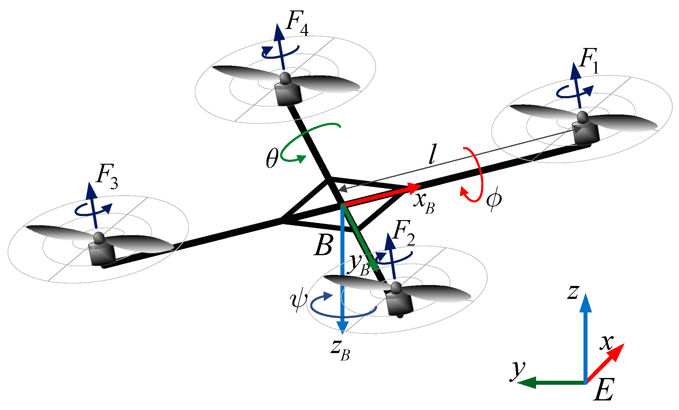
The dynamics model of a quadcopter is described in many existent approaches [44,45,46,47,48,49,50,51]. The essential frames include an Earth frame, E, and body frame, B, as shown in Figure 2. Let ϕ , θ , ψ , ( π / 2 ϕ π / 2 , π / 2 θ π / 2 , π ψ π ) , represent the roll, pitch and yaw angles, respectively. x , y , z denote the position of a quadrotor in the Earth frame. F i (i = 1,2,3,4) represents the thrust force generated by motors i. Ωi denotes the speed of the rotor i. ξ ϕ , ξ θ , ξ ψ , ξ h denote exogenous disturbances which impact on roll, pitch, yaw, and altitude dynamics of the vehicle, respectively. In this paper, the exogenous disturbance is considered as a harmonic disturbance with unknown amplitude but known frequency described by Equation (3).
The dynamics model of the vehicle including exogenous disturbances can be described as follows [44].
[ ϕ ¨ θ ¨ ψ ¨ z ¨ x ¨ y ¨ ] = [ I y y I z z I x x θ ˙ ψ ˙ + θ ˙ J r I x x Ω r + l I x x U 2 I z z I x x I y y ϕ ˙ ψ ˙ ϕ ˙ J r I y y Ω r + l I y y U 3 I x x I y y I z z θ ˙ ϕ ˙ + 1 I z z U 4 g ( cos ϕ cos θ ) U 1 m U 1 m ( cos ϕ sin θ cos ψ + sin ϕ sin ψ ) U 1 m ( cos ϕ sin θ sin ψ sin ϕ cos ψ ) ] + [ ξ ϕ ( t ) ξ θ ( t ) ξ ψ ( t ) ξ h ( t ) 0 0 ]
where U i , i = 1 , 2 , 3 , 4 denote the control inputs of a quadrotor, which are computed as [44]:
[ U 1 U 2 U 3 U 4 Ω r ] = [ b ( Ω 1 2 + Ω 2 2 + Ω 3 2 + Ω 4 2 ) b ( Ω 2 2 + Ω 4 2 ) b ( Ω 1 2 Ω 3 2 ) d ( Ω 1 2 + Ω 2 2 Ω 3 2 + Ω 4 2 ) Ω 1 + Ω 2 Ω 3 + Ω 4 ]
where Ω r represents the total residual angular speed of motors and g = 9.81 m/s2 denotes the gravitational acceleration. The remaining parameters from Equations (32) and (33) are shown in Table 1.
Let X denotes a state vector defined by:
X = [ x 1 , x 2 , , x 12 ] T = [ ϕ , ϕ ˙ , θ , θ ˙ , ψ , ψ ˙ , z , z ˙ , x , x ˙ , y , y ˙ ] T X ˙ = [ x ˙ 1 , x ˙ 2 , , x ˙ 12 ] T = [ ϕ ˙ , ϕ ¨ , θ ˙ , θ ¨ , ψ ˙ , ψ ¨ , z ˙ , z ¨ , x ˙ , x ¨ , y ˙ , y ¨ ] T
where x 1 = ϕ , x 2 = x ˙ 1 = ϕ ˙ , x 3 = θ , x 4 = x ˙ 3 = θ ˙ , x 5 = ψ , x 6 = x ˙ 5 = ψ ˙ , x 7 = z , x 8 = x ˙ 7 = z ˙ , x 9 = x , x 10 = x ˙ 9 = x ˙ , x 11 = y , and x 12 = x ˙ 11 = y ˙ .
Equation (32) can be rewritten in state space as follows:
X ˙ = f ( X ( t ) , U i ( t ) ) + ξ i ( t )
where f ( X ( t ) , U i ( t ) ) = [ x 2 x 4 x 6 a 1 + x 4 a 2 Ω r + b 1 U 2 x 4 x 2 x 6 a 3 + x 2 a 4 Ω r + b 2 U 3 x 6 x 2 x 4 a 5 + b 3 U 4 x 8 g 1 m ( cos x 1 cos x 3 ) U 1 x 10 U 1 m ( cos x 1 sin x 3 cos x 5 + sin x 1 sin x 5 ) x 12 U 1 m ( cos x 1 sin x 3 sin x 5 sin x 1 cos x 5 ) ] , ξ i ( t ) = [ 0 ξ ϕ ( t ) 0 ξ θ ( t ) 0 ξ ψ ( t ) 0 ξ h ( t ) 0 0 0 0 ] , and { a 1 = ( I y y I z z ) / I x x a 2 = J r / I x x a 3 = ( I z z I x x ) / I y y a 4 = ( J r ) / I y y a 5 = ( I x x I y y ) / I z z b 1 = l / I x x b 2 = l / I y y b 3 = 1 / I z z

3.2. Attitude Controller

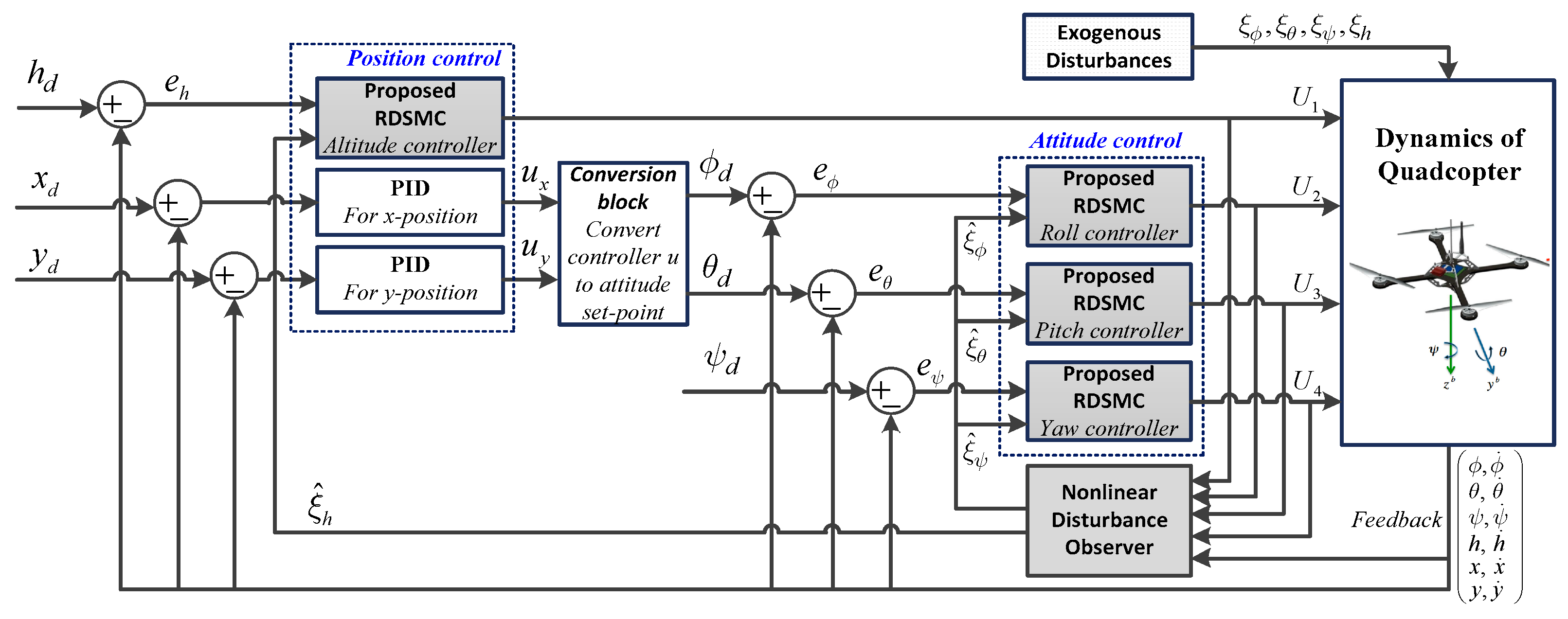
The full control scheme of quadcopter UAVs is constructed as multi-loop comprising an inner loop to control attitude and an outer loop that controls position, as shown in Figure 3.
The roll subsystem described in Equation (35) can be rewritten as follows:
{ x ˙ 1 = x 2 x ˙ 2 = x 4 x 6 a 1 + x 4 a 2 Ω r + b 1 U 2 + ξ ϕ
Let us define f ϕ ( x ) = x 4 x 6 a 1 + x 4 a 2 Ω r , g ϕ ( x ) = b 1 , F ϕ ( x ) = [ x 2 , f ϕ ( x ) ] T , G 1 ϕ ( x ) = [ 0 , g ϕ ( x ) ] T , G 2 ϕ ( x ) = [ 0 , 1 ] T , and H ϕ ( x ) = x 1 . A NDO to estimate the exogenous disturbance in roll subsystem is obtained by Equation (4), as follows:
{ z ˙ ϕ = [ W ϕ l ϕ ( x ) G 2 ϕ ( x ) E ϕ ] z ϕ + W ϕ p ϕ ( x ) l ϕ ( x ) [ G 2 ϕ ( x ) E ϕ p ϕ ( x ) + F ϕ ( x ) + G 1 ϕ ( x ) U 2 ] ϒ ^ ϕ = z ϕ + p ϕ ( x ) ξ ^ ϕ = E ϕ ϒ ^ ϕ
where W ϕ , E ϕ are matrix of exogenous disturbance impacting on the roll subsystem with dimension 2 × 2 and 1 × 2, respectively. The functions p ϕ ( x ) and l ϕ ( x ) are obtained from Equations (7) and (8):
p ϕ ( x ) = [ ε 1 ϕ x 2 ε 2 ϕ x 2 ] , l ϕ ( x ) = [ 0 ε 1 ϕ 0 ε 2 ϕ ] , ε 1 ϕ , ε 2 ϕ > 0
and U 2 is RDSMC controller of the roll subsystem obtained by the two methods in Section 2.2.
Let ϕ d be a desired state of roll control. The tracking error of roll angle and its first derivative are given by: e ϕ = ϕ d x 1 , e ˙ ϕ = ϕ ˙ d x ˙ 1 . The second derivative of tracking error, e ¨ ϕ , is computed by: e ¨ ϕ ( t ) = ϕ ¨ d f ϕ ( x ) g ϕ ( x ) U 2 ξ ϕ . A sliding surface of roll control, s ϕ , and its derivative, s ˙ ϕ , are chosen from Equations (10) and (11) as follows:
s ϕ ( t ) = k p ϕ e ϕ ( t ) + k i ϕ 0 t e ϕ ( τ ) d τ + k d ϕ e ˙ ϕ ( t )
s ˙ ϕ ( t ) = k p ϕ e ˙ ϕ ( t ) + k i ϕ e ϕ ( t ) + k d ϕ e ¨ ϕ ( t ) = k p ϕ e ˙ ϕ ( t ) + k i ϕ e ϕ ( t ) + k d ϕ ( ϕ ¨ d f ϕ ( x ) g ϕ ( x ) U 2 ξ ϕ )
where k p ϕ , k i ϕ , k d ϕ are positive values.
A dynamic sliding surface of roll control, σ ϕ , is given by Equation (12): σ ϕ = s ˙ ϕ + λ ϕ s ϕ , where λ ϕ R + .
Roll controller is obtained from Method 1: RDSMC-PID-NDO is given from Equation (17) as follows:
U ˙ 2 = 1 k d ϕ g ϕ ( x ) ( k d ϕ ( ϕ d f ˙ ϕ ( x ) g ˙ ϕ ( x ) U 2 ξ ^ ˙ ϕ ) + ( k p ϕ + k d ϕ λ ϕ ) ( ϕ ¨ d f ϕ ( x ) g ϕ ( x ) U 2 ξ ^ ϕ ) + ( k i ϕ + λ ϕ k p ϕ ) e ˙ ϕ + λ ϕ k i ϕ e ϕ + β ϕ σ ϕ + k s ϕ sgn ( σ ϕ ) )
where β ϕ , k s ϕ are positive values and satisfy the condition in Equation (16).
Roll controller is obtained from Method 2: RDSMC-PIDSTA-NDO is given in Equation (23) as follows
U ˙ 2 = 1 k d ϕ g ϕ ( x ) ( k d ϕ ( ϕ d f ˙ ϕ ( x ) g ˙ ϕ ( x ) U 2 ξ ^ ˙ ϕ ) + ( k p ϕ + k d ϕ λ ϕ ) ( ϕ ¨ d f ϕ ( x ) g ϕ ( x ) U 2 ξ ^ ϕ ) + ( k i ϕ + λ ϕ k p ϕ ) e ˙ ϕ + λ ϕ k i ϕ e ϕ + k 1 ϕ | σ ϕ | 1 / 2 sgn ( σ ϕ ) + k 2 ϕ 0 t sgn ( σ ϕ ) d t )
where k 1 ϕ , k 2 ϕ are positive values and satisfy the condition in Equation (24).
The pitch subsystem described in Equation (35) can be rewritten as follows:
{ x ˙ 3 = x 4 x ˙ 4 = x 2 x 6 a 3 + x 2 a 4 Ω r + b 2 U 3 + ξ θ
Let us define f θ ( x ) = x 2 x 6 a 3 + x 2 a 4 Ω r , g θ ( x ) = b 2 , F θ ( x ) = [ x 4 , f θ ( x ) ] T , G 1 θ ( x ) = [ 0 , g θ ( x ) ] T , G 2 θ ( x ) = [ 0 , 1 ] T , and H θ ( x ) = x 3 . A NDO to estimate the exogenous disturbance in pitch subsystem is obtained by Equation (4), as follows:
{ z ˙ θ = [ W θ l θ ( x ) G 2 θ ( x ) E θ ] z θ + W θ p θ ( x ) l θ ( x ) [ G 2 θ ( x ) E θ p θ ( x ) + F θ ( x ) + G 1 θ ( x ) U 3 ] ϒ ^ θ = z θ + p θ ( x ) ξ ^ θ = E θ ϒ ^ θ
where W θ , E θ are matrix of exogenous disturbance impacting on pitch subsystem with dimension 2 × 2 and 1 × 2, respectively. The functions p θ ( x ) and l θ ( x ) are computed from Equations (7) and (8):
p θ ( x ) = [ ε 1 θ x 4 ε 2 θ x 4 ] , l θ ( x ) = [ 0 ε 1 θ 0 ε 2 θ ] , ε 1 θ , ε 2 θ > 0
and U 3 is RDSMC controller of pitch subsystem obtained by the two methods in Section 2.2.
Let θ d be a desired state of pitch control. The tracking error of pitch angle and its first derivative are given by: e θ = θ d x 3 , e ˙ θ = θ ˙ d x ˙ 3 . The second derivative of tracking error, e ¨ θ , is computed by: e ¨ θ ( t ) = θ ¨ d f θ ( x ) g θ ( x ) U 3 ξ θ . A sliding surface of pitch control, s θ , and its derivative, s ˙ θ , are chosen from Equations (10) and (11) as follows:
s θ ( t ) = k p θ e θ ( t ) + k i θ 0 t e θ ( τ ) d τ + k d θ e ˙ θ ( t )
s ˙ θ ( t ) = k p θ e ˙ θ ( t ) + k i θ e θ ( t ) + k d θ e ¨ θ ( t ) = k p θ e ˙ θ ( t ) + k i θ e θ ( t ) + k d θ ( θ ¨ d f θ ( x ) g θ ( x ) U 3 ξ θ )
where k p θ , k i θ , k d θ are positive values.
A dynamic sliding surface of pitch control, σ θ , is given by Equation (12): σ θ = s ˙ θ + λ θ s θ , where λ θ R + .
Pitch controller is obtained from Method 1: RDSMC-PID-NDO is given from Equation (17) as follows:
U ˙ 3 = 1 k d θ g θ ( x ) ( k d θ ( θ d f ˙ θ ( x ) g ˙ θ ( x ) U 3 ξ ^ ˙ θ ) + ( k p θ + k d θ λ θ ) ( θ ¨ d f θ ( x ) g θ ( x ) U 3 ξ ^ θ ) + ( k i θ + λ θ k p θ ) e ˙ θ + λ θ k i θ e θ + β θ σ θ + k s θ sgn ( σ θ ) )
where β θ , k s θ are positive values and satisfy the condition in Equation (16).
Pitch controller is obtained from Method 2: RDSMC-PIDSTA-NDO is given in Equation (23) as follows:
U ˙ 3 = 1 k d θ g θ ( x ) ( k d θ ( θ d f ˙ θ ( x ) g ˙ θ ( x ) U 3 ξ ^ ˙ θ ) + ( k p θ + k d θ λ θ ) ( θ ¨ d f θ ( x ) g θ ( x ) U 3 ξ ^ θ ) + ( k i θ + λ θ k p θ ) e ˙ θ + λ θ k i θ e θ + k 1 θ | σ θ | 1 / 2 sgn ( σ θ ) + k 2 θ 0 t sgn ( σ θ ) d t )
where k 1 θ , k 2 θ are positive values and satisfy the condition in Equation (24).
The yaw subsystem described in Equation (35) can be rewritten as follows:
{ x ˙ 5 = x 6 x ˙ 6 = x 2 x 4 a 5 + b 3 U 4 + ξ ψ
Let us define f ψ ( x ) = x 2 x 4 a 5 , g ψ ( x ) = b 3 , F ψ ( x ) = [ x 6 , f ψ ( x ) ] T , G 1 ψ ( x ) = [ 0 , g ψ ( x ) ] T , G 2 ψ ( x ) = [ 0 , 1 ] T , and H ψ ( x ) = x 5 . A NDO to estimate the exogenous disturbance in yaw subsystem is obtained by Equation (4), as follows:
{ z ˙ ψ = [ W ψ l ψ ( x ) G 2 ψ ( x ) E ψ ] z ψ + W ψ p ψ ( x ) l ψ ( x ) [ G 2 ψ ( x ) E ψ p ψ ( x ) + F ψ ( x ) + G 1 ψ ( x ) U 4 ] ϒ ^ ψ = z ψ + p ψ ( x ) ξ ^ ψ = E ψ ϒ ^ ψ
where W ψ , E ψ are matrix of exogenous disturbance impacting on yaw subsystem with dimension 2 × 2 and 1 × 2, respectively. The functions p ψ ( x ) and l ψ ( x ) are computed from Equations (7) and (8):
p ψ ( x ) = [ ε 1 ψ x 6 ε 2 ψ x 6 ] , l ψ ( x ) = [ 0 ε 1 ψ 0 ε 2 ψ ] , ε 1 ψ , ε 2 ψ > 0
and U 4 is RDSMC controller of yaw subsystem obtained by the two methods in Section 2.2.
Let ψ d be a desired state of yaw control. The tracking error of yaw angle and its first derivative are given by: e ψ = ψ d x 5 , e ˙ ψ = ψ ˙ d x ˙ 5 . The second derivative of tracking error, e ¨ ψ , is computed by: e ¨ ψ ( t ) = ψ ¨ d f ψ ( x ) g ψ ( x ) U 4 ξ ψ . A sliding surface of yaw control, s ψ , and its derivative, s ˙ ψ , are chosen from Equations (10) and (11) as follows:
s ψ ( t ) = k p ψ e ψ ( t ) + k i ψ 0 t e ψ ( τ ) d τ + k d ψ e ˙ ψ ( t )
s ˙ ψ ( t ) = k p ψ e ˙ ψ ( t ) + k i ψ e ψ ( t ) + k d ψ e ¨ ψ ( t ) = k p ψ e ˙ ψ ( t ) + k i ψ e ψ ( t ) + k d ψ ( ψ ¨ d f ψ ( x ) g ψ ( x ) U 4 ξ ψ )
where k p ψ , k i ψ , k d ψ are positive values.
A dynamic sliding surface of yaw control, σ ψ , is given by Equation (12): σ ψ = s ˙ ψ + λ ψ s ψ , where λ ψ R + .
Yaw controller is obtained from Method 1: RDSMC-PID-NDO is given from Equation (17) as follows:
U ˙ 4 = 1 k d ψ g ψ ( x ) ( k d ψ ( ψ d f ˙ ψ ( x ) g ˙ ψ ( x ) U 4 ξ ^ ˙ ψ ) + ( k p ψ + k d ψ λ ψ ) ( ψ ¨ d f ψ ( x ) g ψ ( x ) U 4 ξ ^ ψ ) + ( k i ψ + λ ψ k p ψ ) e ˙ ψ + λ ψ k i ψ e ψ + β ψ σ ψ + k s ψ sgn ( σ ψ ) )
where β ψ , k s ψ are positive values and satisfy the condition in Equation (16).
Yaw controller is obtained from Method 2: RDSMC-PIDSTA-NDO is given in Equation (23) as follows
U ˙ 4 = 1 k d ψ g ψ ( x ) ( k d ψ ( ψ d f ˙ ψ ( x ) g ˙ ψ ( x ) U 4 ξ ^ ˙ ψ ) + ( k p ψ + k d ψ λ ψ ) ( ψ ¨ d f ψ ( x ) g ψ ( x ) U 4 ξ ^ ψ ) + ( k i ψ + λ ψ k p ψ ) e ˙ ψ + λ ψ k i ψ e ψ + k 1 ψ | σ ψ | 1 / 2 sgn ( σ ψ ) + k 2 ψ 0 t sgn ( σ ψ ) d t )
where k 1 ψ , k 2 ψ are positive values and satisfy the condition in Equation (24).

3.3. Altitude Controller

The altitude subsystem described in Equation (35) can be rewritten as follows:
{ x ˙ 7 = x 8 x ˙ 8 = g 1 m cos x 1 cos x 3 U 1 + ξ h
Let us define f h ( x ) = g , g h ( x ) = ( 1 / m ) cos x 1 cos x 3 , F h ( x ) = [ x 8 , f h ( x ) ] T , G 1 h ( x ) = [ 0 , g h ( x ) ] T , G 2 h ( x ) = [ 0 , 1 ] T , and H h ( x ) = x 7 . A NDO to estimate the exogenous disturbance in altitude subsystem is obtained by Equation (4), as follows:
{ z ˙ h = [ W h l h ( x ) G 2 h ( x ) E h ] z h + W h p h ( x ) l h ( x ) [ G 2 h ( x ) E h p h ( x ) + F h ( x ) + G 1 h ( x ) U 1 ] ϒ ^ h = z h + p h ( x ) ξ ^ h = E h ϒ ^ h
where W h , E h are matrix of exogenous disturbance impacting on the altitude subsystem with dimension 2 × 2 and 1 × 2, respectively. The functions p h ( x ) and l h ( x ) are computed from Equations (7) and (8):
p h ( x ) = [ ε 1 h x 8 ε 2 h x 8 ] , l h ( x ) = [ 0 ε 1 h 0 ε 2 h ] , ε 1 h , ε 2 h > 0
and U 1 is RDSMC controller of altitude subsystem obtained by the two methods in Section 2.2.
Let h d be a desired state of altitude control. The tracking error of altitude angle and its first derivative are given by: e h = h d x 7 , e ˙ h = h ˙ d x ˙ 7 . The second derivative of tracking error, e ¨ h , is computed by: e ¨ h ( t ) = h ¨ d f h ( x ) g h ( x ) U 1 ξ h . A sliding surface of altitude control, s h , and its derivative, s ˙ h , are chosen from Equations (10) and (11) as follows:
s h ( t ) = k p h e h ( t ) + k i h 0 t e h ( τ ) d τ + k d h e ˙ h ( t )
s ˙ h ( t ) = k p h e ˙ h ( t ) + k i h e h ( t ) + k d h e ¨ h ( t ) = k p h e ˙ h ( t ) + k i h e h ( t ) + k d h ( h ¨ d f h ( x ) g h ( x ) U 1 ξ h )
where k p h , k i h , k d h are positive values.
A dynamic sliding surface of altitude control, σ h , is given by Equation (12): σ h = s ˙ h + λ h s h , where λ h R + .
Altitude controller is obtained from Method 1: RDSMC-PID-NDO is given from Equation (17) as follows:
U ˙ 1 = 1 k d h g h ( x ) ( k d h ( h d f ˙ h ( x ) g ˙ h ( x ) U 1 ξ ^ ˙ h ) + ( k p h + k d h λ h ) ( h ¨ d f h ( x ) g h ( x ) U 1 ξ ^ h ) + ( k i h + λ h k p h ) e ˙ h + λ h k i h e h + β h σ h + k s h sgn ( σ h ) )
where β h , k s h are positive values and satisfy the condition in Equation (16).
Altitude controller is obtained from Method 2: RDSMC-PIDSTA-NDO is given in Equation (23) as follows
U ˙ 1 = 1 k d h g h ( x ) ( k d h ( h d f ˙ h ( x ) g ˙ h ( x ) U 1 ξ ^ ˙ h ) + ( k p h + k d h λ h ) ( h ¨ d f h ( x ) g h ( x ) U 1 ξ ^ h ) + ( k i h + λ h k p h ) e ˙ h + λ h k i h e h + k 1 h | σ h | 1 / 2 sgn ( σ h ) + k 2 h 0 t sgn ( σ h ) d t )
where k 1 h , k 2 h are positive values and satisfy the condition in Equation (24).

4. Simulation Results and Discussions

A numerical simulation was performed on the attitude and altitude control of UAVs to demonstrate the strict robustness and efficiency of the proposed algorithm, as presented in this section. The advantage of two controllers (i.e., RDSMC-PID-NDO and RDSMC-PIDSTA-NDO) of the proposed RDSMC-NDO method are discussed and compared to recent methods, such as NTSMC, STSMC, and M-STSMC.

4.1. Simulation Assumptions

The numerical simulation was carried out through several assumptions: (i) the parameters of a quadcopter UAV, initial conditions, controller gains, and desired states are given in Table 2 and Table 3; and (ii) the dynamics of attitude (i.e., roll, pitch, and yaw) and altitude were simultaneously affected by the different exogenous disturbances as follows:
t [ 5 , 10 ] sec : { ξ ϕ ( t ) = ξ θ ( t ) = ( 3 t + 5 ) sin ( 2 t + 10 ) ξ ψ ( t ) = ( 2 t ) sin ( t + 5 ) ξ h ( t ) = ( 3 t + 5 ) sin ( t + 10 )
t ( 0 , 5 ) ( 10 , + ) sec : ξ ϕ ( t ) = ξ θ ( t ) = ξ ψ ( t ) = ξ h ( t ) = 0

4.2. Simulation Results

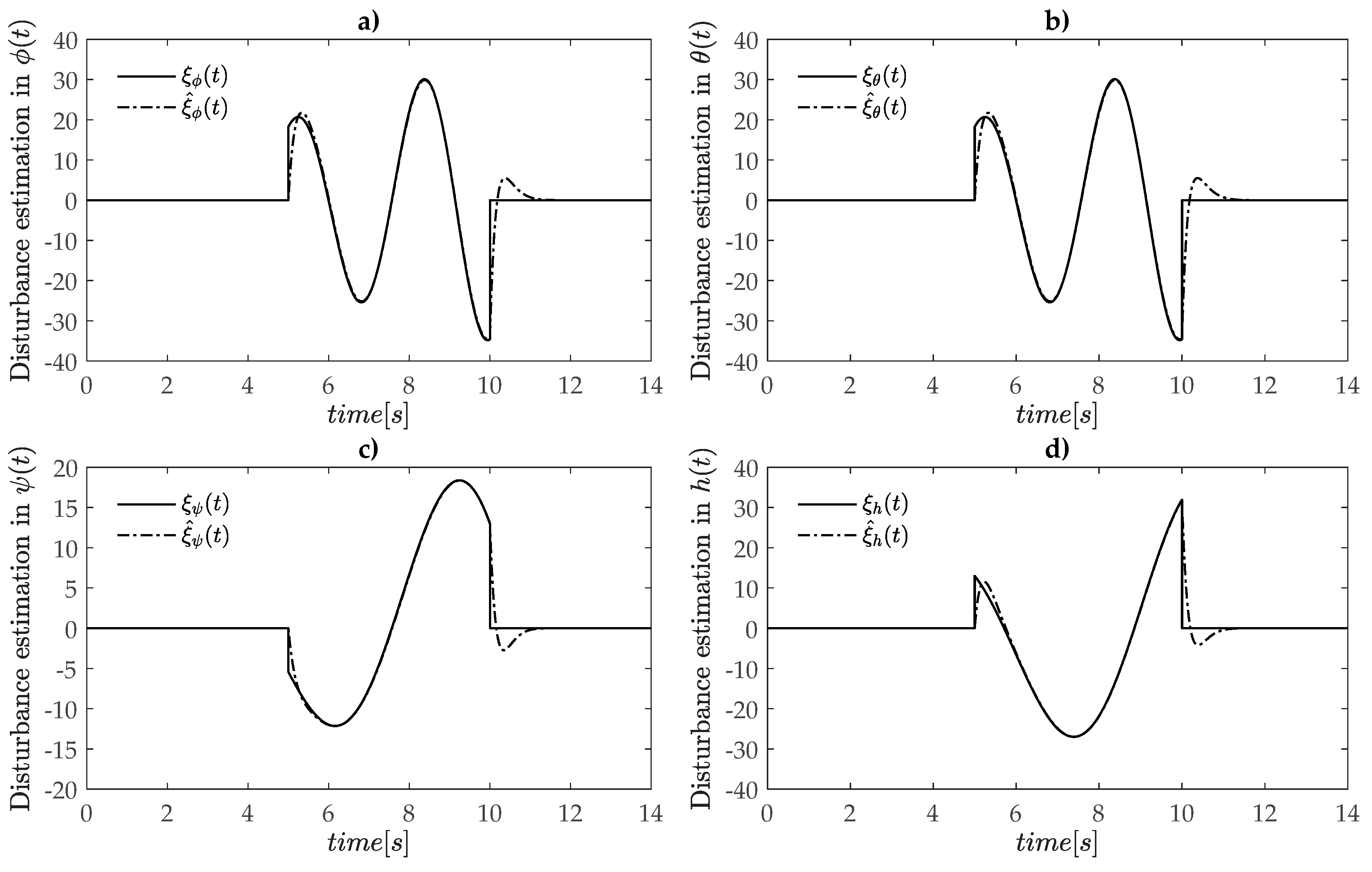
The performance of nonlinear disturbance observer in dynamics of roll, pitch, yaw and altitude is shown in Figure 4. It is easy to see that the disturbance estimation values, ξ ^ ϕ ,   ξ ^ θ ,   ξ ^ ψ ,   and ξ ^ h asymptotically tracked the exogenous disturbances, even if the time-varying oscillation amplitude of perturbation occurred in the movement process of the vehicle.
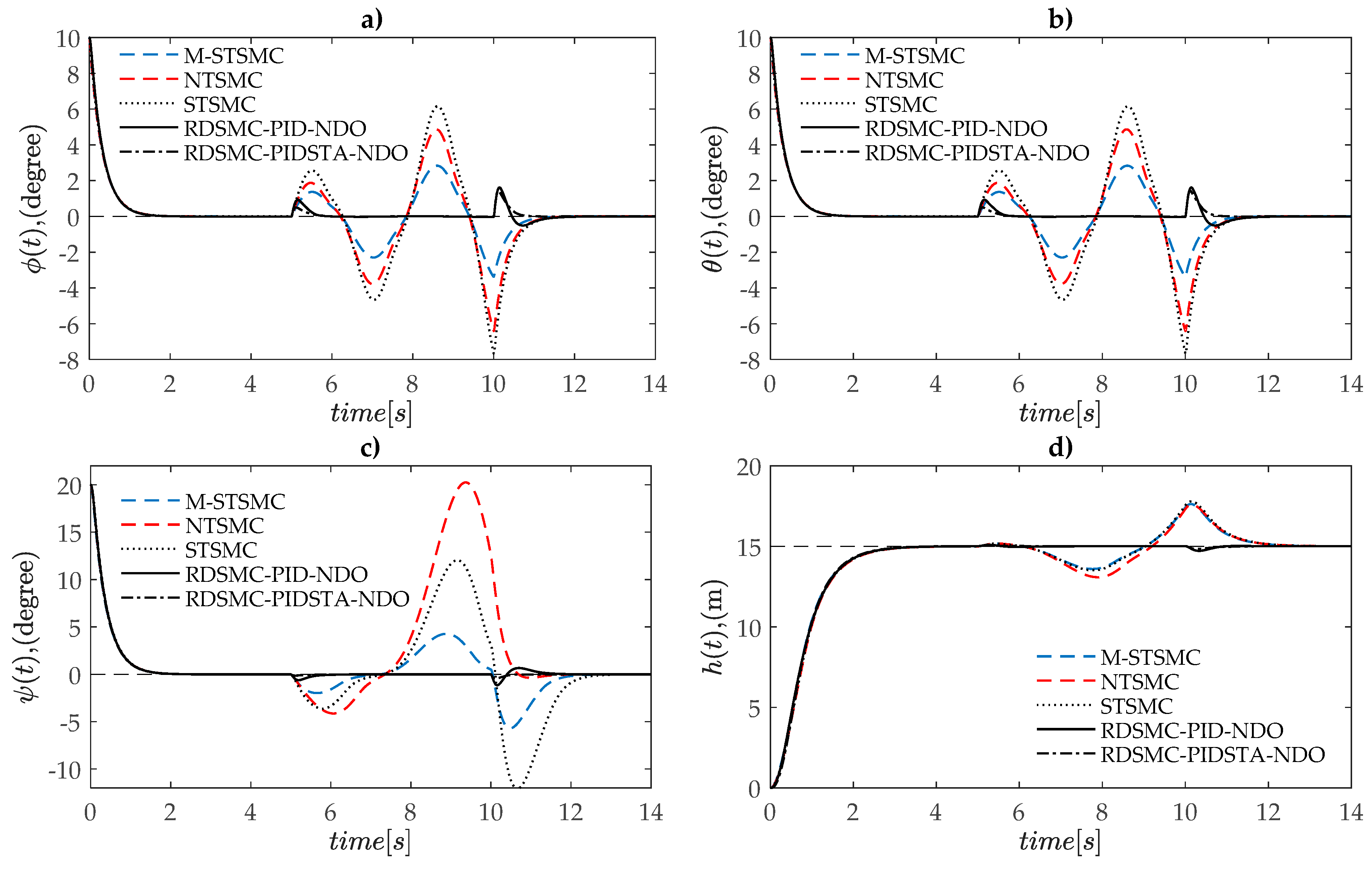
To compare the tracking performance of the two proposed controllers of the RDSMC-NDO (i.e., RDSMC-PID-NDO and RDSMC-PIDSTA-NDO) with other methods, we also carried out numerical simulations on three other methods (i.e., M-STSMC, NTSMC, and STSMC) with the same flight conditions. The comparison of simulation results is shown in Figure 5 and Figure 6. Obviously, the disturbance-free first flight time of the vehicle (t < 5 s), and the responses of φ(t),θ(t), ψ(t), and h(t) were identical for all five controllers, considering both time response and tracking performance (Figure 5). In the second flight stage (5 s ≤ t ≤ 10 s), the various disturbances impacted the system following Equation (64). The proposed RDSMC-NDO exhibited excellent tracking performance with a high robustness compared to other methods (i.e., M-STSMC, NTSMC, and STSMC). It presented small initial oscillation and fast convergence to a steady state, while the other methods generated a large oscillation amplitude and resulted in an unstable performance of the system. In the last flight stage, (t > 10 s), the effect of disturbances on the vehicle suddenly became zero following Equation (65). The proposed method also showed a significantly superior performance for attitude and altitude control with a fast convergence to a steady state.
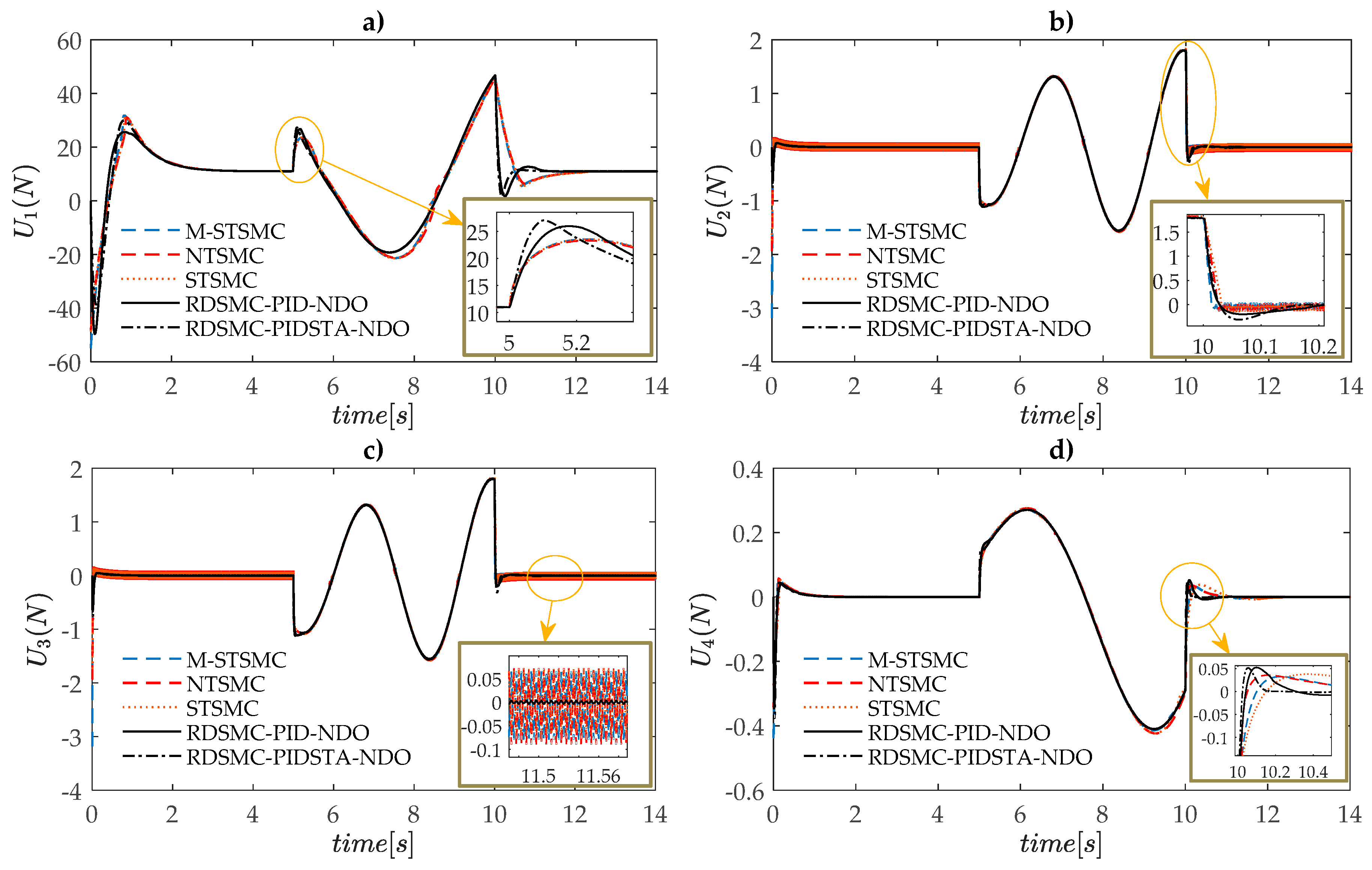
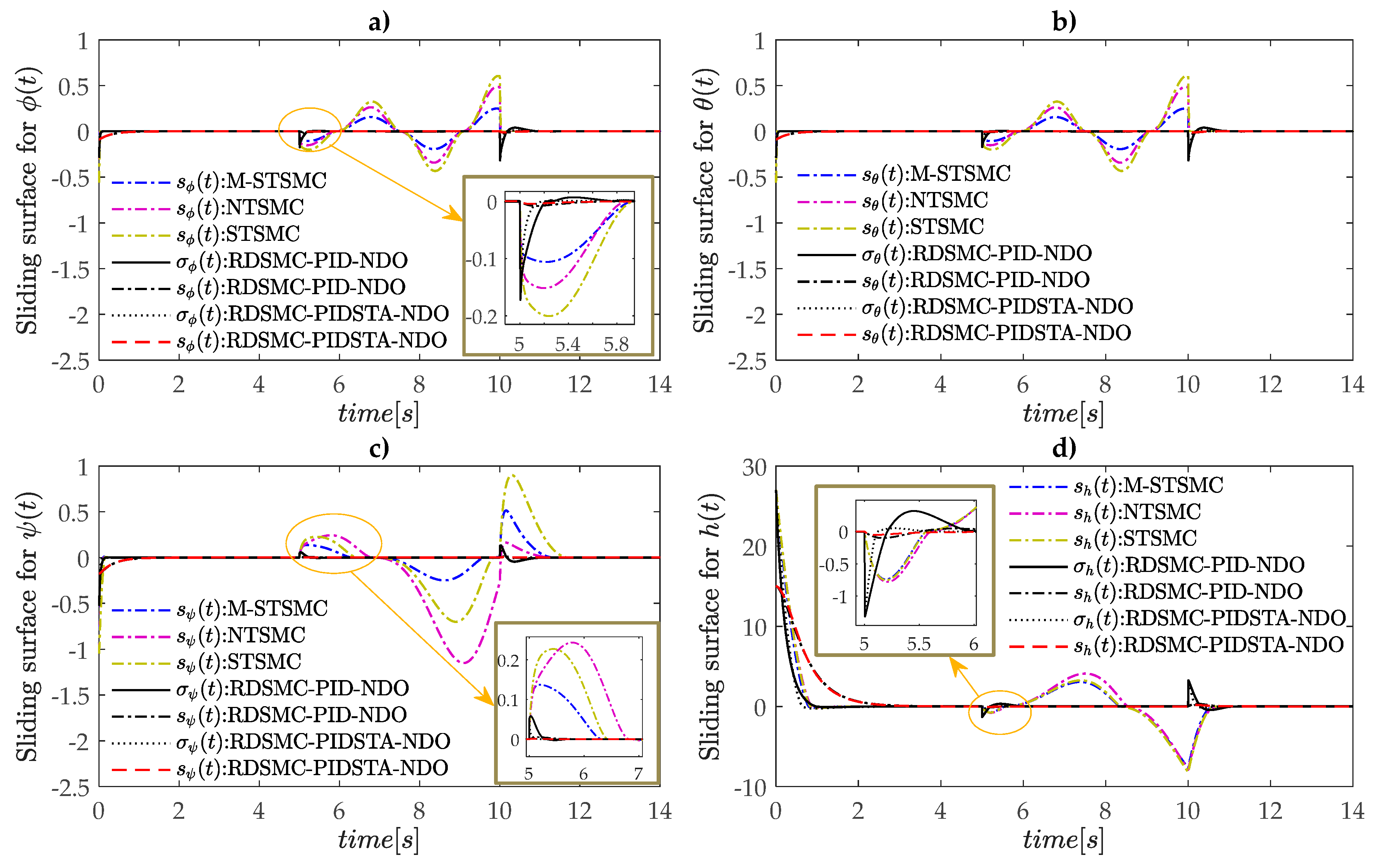
Figure 6 shows the performance of controller signals of attitude (U2, U3, and U4) and altitude (U1). Once the disturbances impacted on the dynamics of the vehicle, the proposed RDSMC-NDO immediately compensated for the influence of perturbations with the chattering effect being strongly eliminated, while the other methods (i.e., M-STSMC, NTSMC, and STSMC) were slower to compensate and generated a chattering in controllers U2 and U3 (Figure 6b,c). In addition, it is easy to see that, in the second flight stage (5 s ≤ t ≤ 10 s), when the various disturbances impacted on the system, the sliding surfaces (sφ, sθ, sψ, and sh) and dynamic sliding surfaces (σφ, σθ, σψ, and σh) of the proposed RDSMC-NDO rapidly converged to zero (about 0.2 s for attitude control and 1 s for altitude control, as shown in Figure 7). The sliding surfaces (sφ, sθ, sψ, and sh) of M-STSMC, NTSMC, and STSMC oscillated and never converged to zero.
In summary, from the results of simulation, it can be seen that all five tested approaches presented an equally excellent performance in the disappearance of exogenous disturbances, i.e., they provided both rapid response and fast convergence to a steady state. However, the different performance appeared once the exogenous disturbances impacted on the dynamics of the vehicle. M-STSMC, NTSMC and STSMC could not adapt well to the fast variation of these perturbations, resulting in a large oscillation amplitude and unstable performance of the control system. This issue was solved by the proposed RDSMC-NDO algorithm. The presented method guaranteed an excellent tracking performance and superior stability of the vehicle with a fast response, good adaptation, and no chattering effect.

5. Conclusions

In this study, we proposed a robust dynamic sliding mode controller based on PID, super twisting algorithm and nonlinear disturbance observer for a second-order nonlinear system, and then the robustness and effectiveness of the proposed method was demonstrated through the control performance of UAVs in both attitude and altitude. In this algorithm, the exogenous disturbance is estimated by a nonlinear disturbance observer. Then, a general design procedure of a robust dynamic sliding mode controller integrated with the estimated values of disturbances is presented by a combination of a PID sliding surface and Super Twisting Algorithm to compensate for the effect of these perturbations on the system. As the simulation results, the robustness and efficiency of the proposed algorithm were demonstrated by an excellent tracking performance and superior stability of attitude and altitude control of UAVs with a fast response, good adaptation, and no chattering effect. However, the study did not cover the undesirable effects of inharmonic disturbance. Therefore, the same problem with an arbitrary perturbation will be studied in the future.

Author Contributions

Conceptualization, L.N.N.T.H. and S.K.H.; methodology, L.N.N.T.H. and S.K.H; software, L.N.N.T.H.; validation, L.N.N.T.H.; formal analysis, L.N.N.T.H.; resources, L.N.N.T.H.; data curation, L.N.N.T.H.; writing—original draft preparation, L.N.N.T.H.; writing—review and editing, L.N.N.T.H.; visualization, L.N.N.T.H. and S.K.H; supervision, S.K.H.; project administration, S.K.H.; and funding acquisition, S.K.H.

Acknowledgments

This research was supported by the MSIT (Ministry of Science and ICT), Korea, under the ITRC (Information Technology Research Center) support program (IITP-2019-2018-0-01423) supervised by the IITP (Institute for Information & communications Technology Promotion) and the faculty research fund of Sejong University in 2019.

Conflicts of Interest

The authors declare no conflict of interest.

References

  1. Zheng, E.H.; Xiong, J.J.; Luo, J.L. Second order sliding mode control for a quadrotor UAV. ISA Trans. 2014, 53, 1350–1356. [Google Scholar] [CrossRef] [PubMed]
  2. Xiong, J.J.; Zhang, G.B. Global fast dynamic terminal sliding mode control for a quadrotor UAV. ISA Trans. 2017, 66, 233–240. [Google Scholar] [CrossRef] [PubMed]
  3. Su, J.; Yang, J.; Li, S. Continuous finite-time anti-disturbance control for a class of uncertain nonlinear systems. Trans. Inst. Meas. Control 2014, 36, 300–311. [Google Scholar] [CrossRef]
  4. Yang, J.; Su, J.; Li, S.; Yu, X. High-order mismatched disturbance compensation for motion control systems via a continuous dynamic sliding-mode approach. IEEE Trans. Ind. Inform. 2014, 10, 604–614. [Google Scholar] [CrossRef]
  5. Barghandan, S.; Badamchizadeh, M.A.; Motlagh, M.R.J. Improved adaptive fuzzy sliding mode controller for robust fault tolerant of a quadrotor. Int. J. Control Autom. Syst. 2017, 15, 427–441. [Google Scholar] [CrossRef]
  6. Van, M. An enhanced robust fault tolerant control based on an adaptive fuzzy PID-nonsingular fast terminal sliding mode control for uncertain nonlinear systems. IEEE/ASME Trans. Mechatron. 2018, 23, 1362–1371. [Google Scholar] [CrossRef]
  7. Zhang, J.; Shi, P.; Xia, Y. Robust adaptive sliding–mode control for fuzzy systems with mismatched uncertainties. IEEE Trans. Fuzzy Syst. 2010, 18, 700–711. [Google Scholar] [CrossRef]
  8. Gong, X.; Hou, Z.C.; Zhao, C.J.; Bai, Y.; Tian, Y.T. Adaptive backstepping sliding mode trajectory tracking control for a quadrotor. Int. J. Autom. Comput. 2012, 9, 555–560. [Google Scholar] [CrossRef]
  9. Rodriguez, H.R.; Vega, V.P.; Orta, A.S.; Salazar, O.G. Robust backstepping control based on integral sliding mode for tracking of quadrotors. J. Intell. Robot. Syst. 2014, 73, 51–66. [Google Scholar] [CrossRef]
  10. Chen, F.; Jiang, R.; Zhang, K.; Jiang, B.; Tao, G. Robust backstepping sliding-mode control and observer-based fault estimation for a quadrotor UAV. IEEE Trans. Ind. Electron. 2016, 63, 5044–5056. [Google Scholar] [CrossRef]
  11. Lee, T. Robust adaptive attitude tracking on SO3 with an application to a quadrotor UAV. IEEE Trans. Control Syst. Technol. 2013, 21, 1924–1930. [Google Scholar]
  12. Mofid, O.; Mobayen, S. Adaptive sliding mode control for finite-time stability of quad-rotor UAVs with parametric uncertainties. ISA Trans. 2018, 72, 1–14. [Google Scholar] [CrossRef] [PubMed]
  13. Zhao, B.; Xian, B.; Zhang, Y.; Zhang, X. Nonlinear robust adaptive tracking control of a quadrotor UAV via immersion and invariance methodology. IEEE Trans. Ind. Electron. 2015, 62, 2891–2902. [Google Scholar] [CrossRef]
  14. Li, S.; Wang, Y.; Tan, J. Adaptive and robust control of quadrotor aircrafts with input saturation. Nonlinear Dyn. 2017, 89, 255–265. [Google Scholar] [CrossRef]
  15. Liu, H.; Xi, J.; Zhong, Y. Robust attitude stabilization for nonlinear quadrotor systems with uncertainties and delays. IEEE Trans. Ind. Electron. 2017, 64, 5585–5594. [Google Scholar] [CrossRef]
  16. Nadda, S.; Swarup, A. On adaptive sliding mode control for improved quadrotor tracking. J. Vib. Control 2017, 24, 3219–3230. [Google Scholar] [CrossRef]
  17. Thanh, H.L.; Hong, S.K. Quadcopter robust adaptive second order sliding mode control based on PID sliding surface. IEEE Access 2018, 6, 66850–66860. [Google Scholar] [CrossRef]
  18. Rios, H.; Sierra, J.G.; Dzul, A. Robust tracking output-control for a quad-rotor: A continuous sliding-mode approach. J. Frankl. Inst. 2017, 354, 6672–6691. [Google Scholar] [CrossRef]
  19. Dydek, Z.T.; Annaswamy, A.M.; Lavretsky, E. Adaptive control of quadcopter UAVs: A design trade study with flight evaluations. IEEE Trans. Control Syst. Technol. 2013, 21, 1400–1406. [Google Scholar] [CrossRef]
  20. MacKunis, W.; Wilcox, Z.D.; Kaiser, M.K.; Dixon, W.E. Global adaptive output feedback tracking control of an unmanned aerial vehicle. IEEE Trans. Control Syst. Technol. 2010, 18, 1390–1397. [Google Scholar] [CrossRef]
  21. Le, M.; Cheng, Y. Robust adaptive sliding mode control for switched networked control systems with disturbance and faults. IEEE Trans. Ind. Inform. 2019, 15, 193–204. [Google Scholar]
  22. Mystkowski, A. Implementation and investigation of a robust control algorithm for an unmanned micro-aerial vehicle. Robot. Auton. Syst. 2014, 62, 1187–1196. [Google Scholar] [CrossRef]
  23. Mystkowski, A. An application of mu-synthesis for control of a small air vehicle and simulation results. J. Vibroengineering 2012, 14, 79–86. [Google Scholar]
  24. Li, S.; Wang, Y.; Tan, J.; Zheng, Y. Adaptive RBFNNs/integral sliding mode control for a quadrotor aircraft. Neurocomputing 2016, 216, 126–134. [Google Scholar] [CrossRef]
  25. Yin, Y.; Niu, H.; Liu, X. Adaptive neural network sliding mode control for quad tilt rotor aircraft. Complexity 2017, 2017, 7104708. [Google Scholar] [CrossRef]
  26. Peng, C.; Bai, Y.; Gong, X.; Gao, Q.; Zhao, C.; Tian, Y. Modeling and robust backstepping sliding mode control with adaptive RBFNN for a novel coaxial eight-rotor UAV. IEEE/CAA J. Autom. Sin. 2015, 2, 56–64. [Google Scholar]
  27. Razmi, H.; Afshinfar, S. Neural network-based adaptive sliding mode control design for position and attitude control of a quadrotor UAV. Aerosp. Sci. Technol. 2019, 91, 12–27. [Google Scholar] [CrossRef]
  28. Ejaz, F.; Hamayun, M.T.; Hussian, S.; Ljaz, S.; Yang, S.; Shehzad, N.; Rashid, A. An adaptive sliding mode actuator fault tolerant control scheme for octorotor system. Int. J. Adv. Robot. Syst. 2019, 16. [Google Scholar] [CrossRef]
  29. Lei, X.; Guo, K.; Ge, S.S. Disturbance observer based control of small unmanned aerial rotorcraft. Math. Probl. Eng. 2013, 2013, 464938. [Google Scholar] [CrossRef]
  30. Smith, J.; Su, J.; Liu, C.; Chen, W.H. Disturbance observer based control with anti-windup applied to a small fixed wing UAV for disturbance. J. Intell. Robot. Syst. 2017, 88, 329–346. [Google Scholar] [CrossRef]
  31. Besnard, L.; Shtessel, Y.B.; Landrum, B. Quadrotor vehicle control via sliding mode controller driven by sliding mode disturbance observer. J. Frankl. Inst. 2012, 349, 658–684. [Google Scholar] [CrossRef]
  32. Ahmed, N.; Chen, M. Sliding mode control for quadrotor with disturbance observer. Adv. Mech. Eng. 2018, 10, 1–16. [Google Scholar] [CrossRef]
  33. Zhou, Z.; Zhang, B.; Mao, D. Robust sliding mode control of PMSM based on rapid nonlinear tracking differentiator and disturbance observer. Sensor 2018, 18, 1031. [Google Scholar] [CrossRef] [PubMed]
  34. Munoz, F.; Hernandez, I.G.; Salazar, S.; Espinoza, E.S.; Lozano, R. Second order sliding mode controllers for altitude control of a quadrotor UAS: Real-time implementation in outdoor environments. Neurocomputing 2017, 233, 61–71. [Google Scholar] [CrossRef]
  35. Akbar, R.; Uchiyama, N. Adaptive modified super-twisting control for a quadrotor helicopter with a nonlinear sliding surface. In Proceedings of the SICE International Symposium on Control System (SICE ISCS), Okayama, Japan, 6–9 March 2017; pp. 1–6. [Google Scholar]
  36. Tran, M.D.; Kang, H.J. Nonsingular terminal sliding mode control of uncertain second-order nonlinear systems. Math. Probl. Eng. 2015, 2015, 181737. [Google Scholar] [CrossRef]
  37. Derafa, L.; Benallegue, A.; Fridman, L. Super twisting control algorithm for the attitude tracking of a four rotors UAV. J. Frankl. Inst. 2012, 349, 685–699. [Google Scholar] [CrossRef]
  38. Wang, J.Y.; Luo, B.; Zeng, M.; Meng, Q.H. A wind estimation method with an unmanned rotorcraft for environmental monitoring tasks. Sensors 2018, 18, 4504. [Google Scholar] [CrossRef] [PubMed]
  39. Langelaan, J.W.; Alley, N.; Neidhoefer, J. Wind field estimation for small unmanned aerial vehicles. J. Guid. ControlDyn. 2011, 34, 1016–1030. [Google Scholar] [CrossRef]
  40. Song, Y.; Luo, B.; Meng, Q.H. A rotor-aerodynamics-based wind estimation method using a quadrotor. Meas. Sci. Technol. 2018, 29, 025801. [Google Scholar] [CrossRef]
  41. Chen, W.H. Disturbance observer based control for nonlinear systems. IEEE/ASME Trans. Mechatron. 2004, 9, 706–710. [Google Scholar] [CrossRef]
  42. Moreno, J.A.; Osorio, M. A Lyapunov approach to second-order sliding mode controllers and observers. In Proceedings of the 47th IEEE conference on Decision and Control, Cancun, Mexico, 9–11 December 2008. [Google Scholar]
  43. Moreno, J.A.; Osorio, M. Strict Lyapunov functions for the super-twisting algorithm. IEEE Trans. Autom. Control 2012, 57, 1035–1040. [Google Scholar] [CrossRef]
  44. Alexis, K.; Nikolakopoulos, G.; Tzes, A. Model predictive quadrotor control: Attitude, altitude and position experimental studies. IET Control Theory Appl. 2012, 6, 1812–1827. [Google Scholar] [CrossRef]
  45. Raffo, G.V.; Ortega, M.G.; Rubio, F.R. An integral predictive/nonlinear H control structure for a quadrotor helicopter. Automatica 2010, 46, 29–39. [Google Scholar] [CrossRef]
  46. Jia, Z.; Yu, J.; Mei, Y.; Chen, Y.; Shen, Y.; Ai, X. Integral backstepping sliding mode control for quadrotor helicopter under external uncertain disturbances. Aerosp. Sci. Technol. 2017, 68, 299–307. [Google Scholar] [CrossRef]
  47. Alexis, K.; Nikolakopoulos, G.; Tzes, A. Switching model predictive attitude control for a quadrotor helicopter subject to atmospheric disturbances. Control Eng. Pract. 2011, 19, 1195–1207. [Google Scholar] [CrossRef] [Green Version]
  48. Ha, L.N.; Bui, D.H.; Hong, S.K. Nonlinear control for autonomous trajectory tracking while considering collision avoidance of UAVs based on geometric relations. Energies 2019, 12, 1551. [Google Scholar] [CrossRef]
  49. Thanh, H.L.; Hong, S.K. Completion of collision avoidance control algorithm for multicopters based on geometrical constrains. IEEE Access 2018, 6, 27111–27125. [Google Scholar] [CrossRef]
  50. Thanh, H.L.; Phi, N.N.; Hong, S.K. Simple nonlinear control of quadcopter for collision avoidance based on geometric approach in static environment. Int. J. Adv. Robot. Syst. 2018, 15, 1–17. [Google Scholar] [CrossRef]
  51. Wang, H.; Ye, X.; Tian, Y.; Zheng, G.; Christov, N. Model-free-based terminal SMC of quadrotor attitude and position. IEEE Trans. Aerosp. Electron. Syst. 2016, 52, 2519–2528. [Google Scholar] [CrossRef]
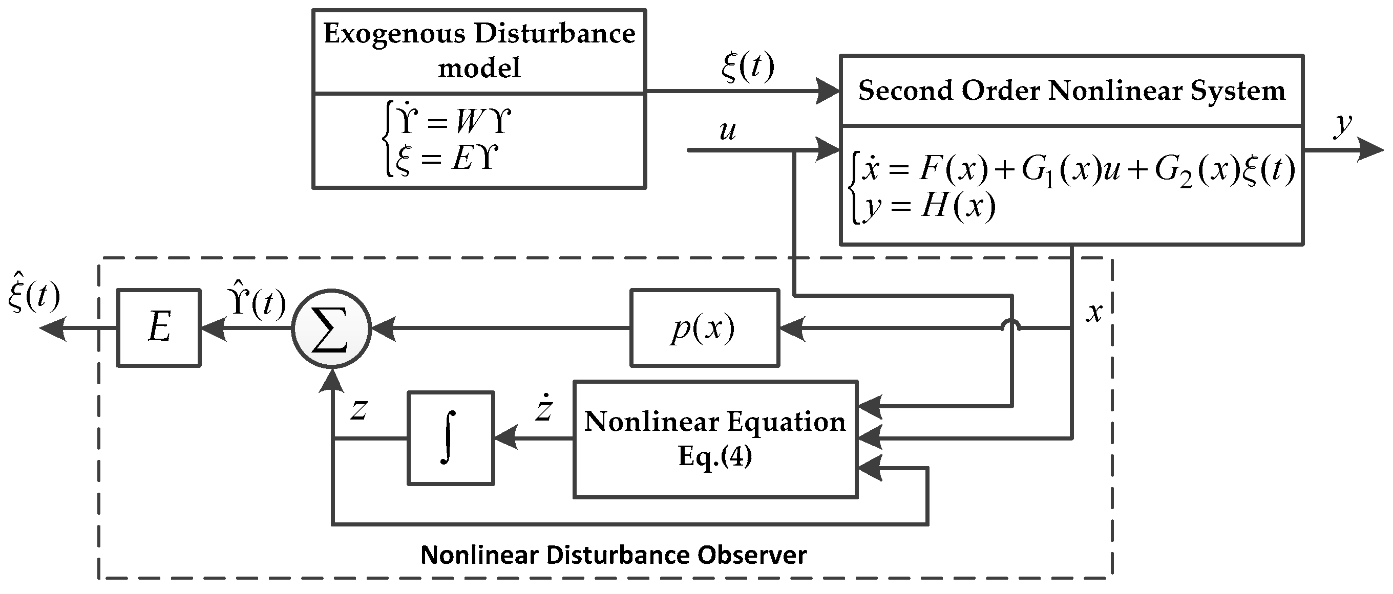
Figure 1. General structure of NDO for harmonic disturbances.
Electronics 08 00760 g001
Figure 2. Quadcopter’s configuration.
Electronics 08 00760 g002
Figure 3. Block diagram of full controller of a quadcopter, the proposed algorithm is applied in the attitude and altitude control only. The traditional PID is used in horizontal position control.
Electronics 08 00760 g003
Figure 4. Performance of disturbance observer: (a) in roll dynamics; (b) in pitch dynamics; (c) in yaw dynamics; and (d) in altitude dynamics.
Electronics 08 00760 g004
Figure 5. Comparison of attitude and altitude performance between the proposed RDSMC-NDO method and other approaches: (a) roll control performance; (b) pitch control performance; (c) yaw control performance; and (d) altitude control performance.
Electronics 08 00760 g005
Figure 6. Comparison of attitude and altitude controller between the proposed RDSMC-NDO method and other approaches: (a) altitude controller U1; (b) roll controller U2; (c) pitch controller U3; and (d) yaw controller U4.
Electronics 08 00760 g006
Figure 7. Comparison the sliding surfaces of attitude and altitude controller between the proposed RDSMC-NDO method and other approaches: (a) roll control; (b) pitch control; (c) yaw control; and (d) altitude control.
Electronics 08 00760 g007
Table 1. System parameters of a quadcopter.
System ParametersDescriptions
Ixx, Iyy, Izz (kgm2)Moments of inertia along three axes x,y and z in the Earth frame
m (kg)Total mass of a quadcopter
l (m)Arm length of the quadcopter frame
b (Ns2)Thrust coefficient
d (Nms2)Drag coefficient
Jr (kgm2)Moment of inertial of a rotor
Table 2. System parameters of the quadcopter for simulation.
SymbolDescriptionsValue and Unit
mTotal mass of quadcopter1.12 kg
IxxMoment of inertia along x-axis0.0119 kg.m2
IyyMoment of inertia along y-axis0.0119 kg.m2
IzzMoment of inertia along z-axis0.0223 kg.m2
bThrust coefficient 7.73213 (10−6) Ns2
dDrag coefficient1.27513 (10−7) Nms2
JrMoment of inertial of a rotor8.5(10−4) kgm2
lArm length0.23 m
ϕ 0 ; ϕ d Initial and desired states of roll controller10; 0 degree
θ 0 ; θ d Initial and desired states of pitch controller10; 0 degree
ψ 0 ; ψ d Initial and desired states of yaw controller20; 0 degree
h 0 ; h d Initial and desired states of altitude controller0; 15 m
Table 3. Parameters of the proposed RDSMC-NDO for simulation.
Symbol Roll (φ)Pitch (θ)Yaw (ψ)Altitude (h)
k p 0.50.50.51.0
k i 0.0010.0010.0010.001
k d 0.0080.0080.0080.1
λ3.33.33.01.8
β6060304.5
k s 0.50.50.11.0
k 1 30302015
k 2 0.10.10.11.0
ε 1 10101010
ε 2 12123030