Article

Research on Application of Non-Isolated Three-Port Switching Boost Converter in Photovoltaic Power Generation System

1
Electrical and Control Engineering College, North China University of Technology, Beijing 100144, China
2
Beijing Electric Power Energy-Saving Key Technology Collaborative Innovation Center, Beijing 100144, China
*
Author to whom correspondence should be addressed.
Electronics 2019, 8(7), 746; https://doi.org/10.3390/electronics8070746
Submission received: 14 May 2019 / Revised: 21 June 2019 / Accepted: 25 June 2019 / Published: 2 July 2019
(This article belongs to the Section Power Electronics)

Abstract

:
This paper presents a non-isolated three-port switching boost converter and applies it to photovoltaic systems. The topology combines the characteristics of the switching boost network. By controlling three degrees of freedom, the ports have boost, buck, and buck-boost characteristics. It expands the three-port converter (TPC) working range with the advantages of simple structure, small size, and low cost. The operating mode and power flow direction of the TPC are determined according to the state of charge (SOC) of the energy storage system. Analyses of the working state of the topology in different working modes further verify the power flow of the system and explain its control strategy to complete the smooth switching of different working modes. Finally, the correctness of the above theory and its feasibility in photovoltaic system are verified by simulation and experiment.

1. Introduction

With the development of the social economy and the progress of human industrial civilization, the traditional fossil energy reserves have declined sharply, and renewable energy has been gradually applied to various fields. As one of the emerging energy sources, solar energy is of great significance for mitigating the energy crisis and environmental pollution [1,2]. Since solar energy is affected by light intensity and time, it is unstable and unsustainable. Therefore, it is necessary to introduce an energy storage unit for balancing system power in an independent renewable power system to provide energy to the load side [3,4,5,6,7,8,9,10]. The traditional renewable energy supply system consists of multiple independent converters connected to the input source, energy storage battery and load, which makes the system bulky, costly and reliable [11]. The three-port converter (TPC) is ideal for connecting renewable energy, energy storage units and loads in new energy generation systems. It has the advantages of smaller size, fewer components and uniform energy flow management between ports, which can reduce the volume and weight of the system and reduce the loss of the system [12,13,14,15,16]. In order to further understand the TPC, some scholars have conducted various in-depth explorations. They have proposed various types of topologies and control strategies. TPC can be divided into two categories in terms of topology, isolated TPC and non-isolated TPC. The isolated TPC can be further divided into a fully isolated TPC and a partially isolated TPC [17,18,19]. The isolated TPC for power management in the vehicle power system eliminates the auxiliary circuit for soft switching, saving cost and simple control, but the disadvantage is that the conversion efficiency is low, and the overall volume is largely due to the coupling of multiple transformer windings [20]. The partially isolated TPC can achieve non-isolated power flow between the main power supply and the battery and it is isolated from the load side, enabling soft switching but low duty cycle utilization and high loss. For applications that do not require electrical isolation, non-isolated TPCs can achieve higher power densities, and relatively isolated topologies eliminate the need for transformers, reducing system losses [21,22]. The non-isolated TPC topology achieves power flow management by controlling four degrees of freedom. It has the advantages of small size and low cost, but the TPC is limited by the port voltage and has a limited operating range. This paper proposes a non-isolated three-port switching boost converter that combines the characteristics of a switching boost network for the photovoltaic system to achieve dynamic tracking of the system’s maximum power point. The TPC controls three degrees of freedom to complete system power flow management and smooth switching in different power flow modes.

2. System Topology Circuit Analysis

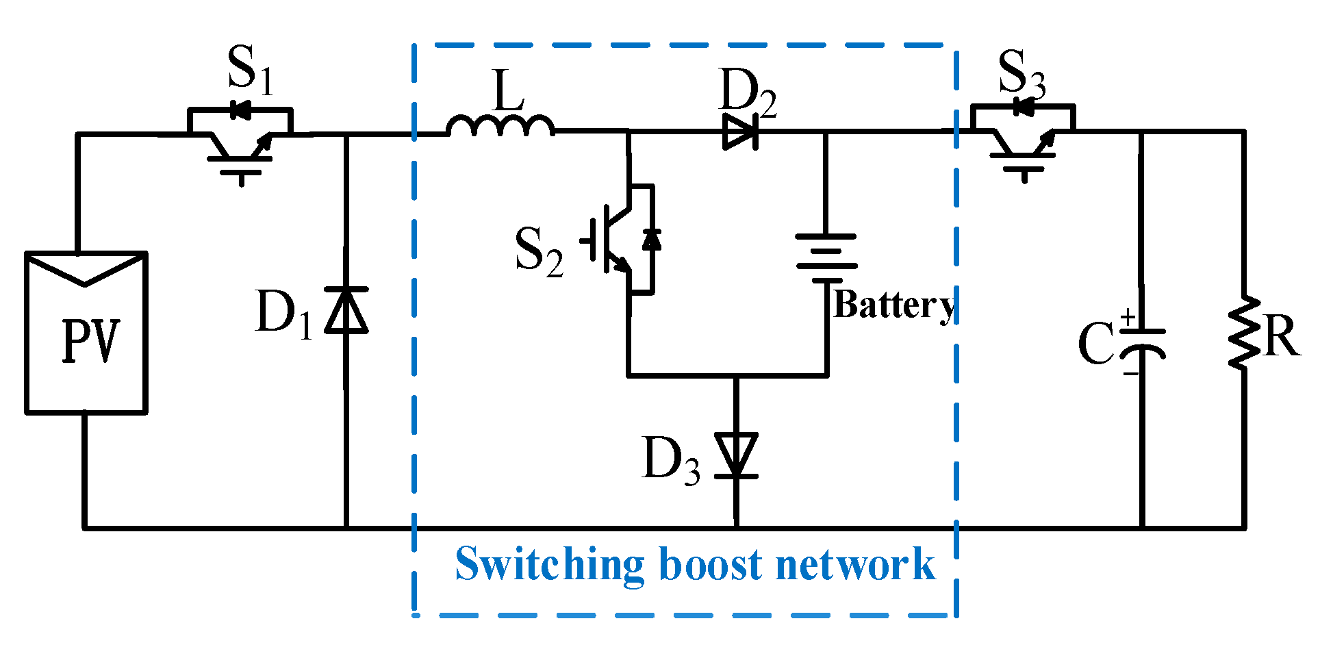
2.1. Three-Port Switching Boost Converter Topology

Figure 1 shows a non-isolated three-port switching boost converter topology with a variable structure. This topology consists of a photovoltaic input source (Vin), a battery, a DC load (R), three switches (S1–S3), three diodes (D1–D3), an inductor L and a capacitor C. Since this topology combines the characteristics of the switching boost network, omitting the power converter of the battery back end in the traditional energy storage system, the system structure is simple. By controlling the state of the three switches, the port has boost, buck and buck–boost characteristics [23]. The topology uses only one inductor, it has the advantages of a compact package and unified power flow management between ports.

2.2. Three-Port Switching Boost Converter Topology

Since the topology includes three switches S1, S2 and S3, there are eight operating states, as shown in Figure 2. The corresponding switch state and the number of ports flowing through are different, as shown in Table 1 (where 1, 0 represents the on state and the off state of the switches S1, S2 and S3, respectively). For each operating state, the inductor current transfers energy from one or two ports to another port or ports. According to Kirchhoff’s voltage law, the voltage balance Equations (1)–(8) in the following eight operating states can be obtained.
L d i d t = V b
V in = L d i d t + V b
L d i d t = 0
L d i d t = V o
V in = L d i d t
V in = L d i d t + V o
L d i d t + V b = V o
V in = L d i d t V b + V o
where Vin is the input voltage, Vb is the voltage across the battery, Vo is the output voltage, and i is the inductor current.

2.3. TPC Power Flow Relationship

The power flow mode and state of charge (SOC) judgment relationship of the three-port switching boost converter are shown in Figure 3. When one of the ports of the TPC is removed and the remaining two ports perform energy transfer, the TPC is in single input single output (SISO) mode. When the illumination is weak, the power Ppv provided by the PV side is lower than the required power Pref of the load side, and the battery is discharged as a supply together with the solar panel, the three-port converter operates in the dual input single output mode (DISO). When the battery SOC reaches the lower threshold SOCmin, the battery does not have the discharge capability, and the three-port converter cannot operate in the DISO mode. When the light is sufficient, the power Ppv provided by the PV side is higher than the power required by the load side Pref, the battery absorbs excess power, and the three-port converter operates in single input dual output (SIDO) mode. When the battery SOC reaches the upper threshold SOCmax, the battery does not have the charging capability and the three-port converter cannot operate in the SIDO mode at this time. When the power Ppv supplied from the PV side is equal to the required power Pref on the load side, the battery operates in a state of neither charging nor discharging.
In the SIDO working mode, the topology circuit can be turned on and off by controlling the switches S1, S2 and S3, the buck, buck-boost or boost characteristics can be obtained between the ports, so that the TPC can work in Vin > Vb > Vo, Vb > Vin > Vo, Vb > Vo > Vin working condition. Figure 4 and Figure 5 show waveforms and the three operating states (110→001→000) of the non-isolated three-port switching boost converter that supplies power to the battery and load during a switching cycle in SIDO mode when the topology is operating at Vb > Vin > Vo. As shown in Figure 4 and Figure 5, when the TPC operates in the state of Figure 5a, it corresponds to the period t0 to t1 in Figure 4, the switches S1 and S2 are in an on the state, S3 is in an off state, the diode D3 is in an on state, the solar panel transmits energy to the inductor, and the inductor L is charged. In the period from t1 to t2 in Figure 4, the state of Figure 5b, the switch S3 is in the on the state, the switches S1 and S2 are in the off state and the freewheeling diode D1 is turned on, energy is transferred from the inductor to the load. When the TPC operates in the period from t2 to t3 in Figure 4, the operating state is switched from state Figure 5b to state Figure 5c, switch S3 is turned off, the diode D3 is turned on, and the inductor L supplies power to the battery. According to the volt-second balance principle, the Equation (9) can be obtained by the Equations (1), (4) and (5), and Equation (10) of Vin, Equation (11) of Vb and Equation (12) of Vo can be obtained.
V in d 1 = V o d 3 + V b ( 1 d 1 d 3 )
V in = V o d 3 + V b ( 1 d 1 d 3 ) d 1
V b = V in d 1 V o d 3 ( 1 d 1 d 3 )
V o = V in d 1 V b ( 1 d 1 d 3 ) d 3
where d1 and d3 are the duty ratios of the switches S1 and S3 respectively in one switching cycle.

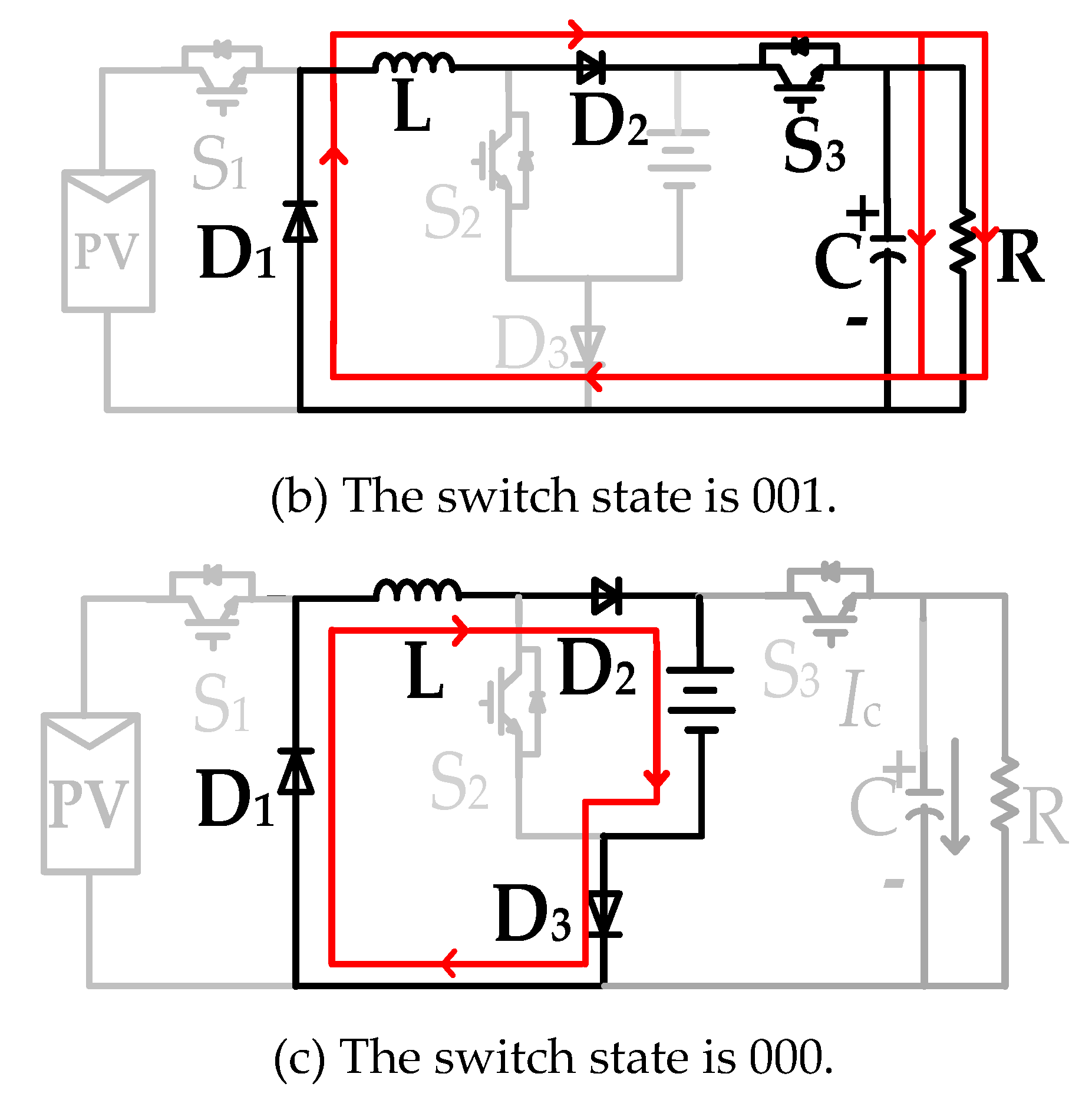
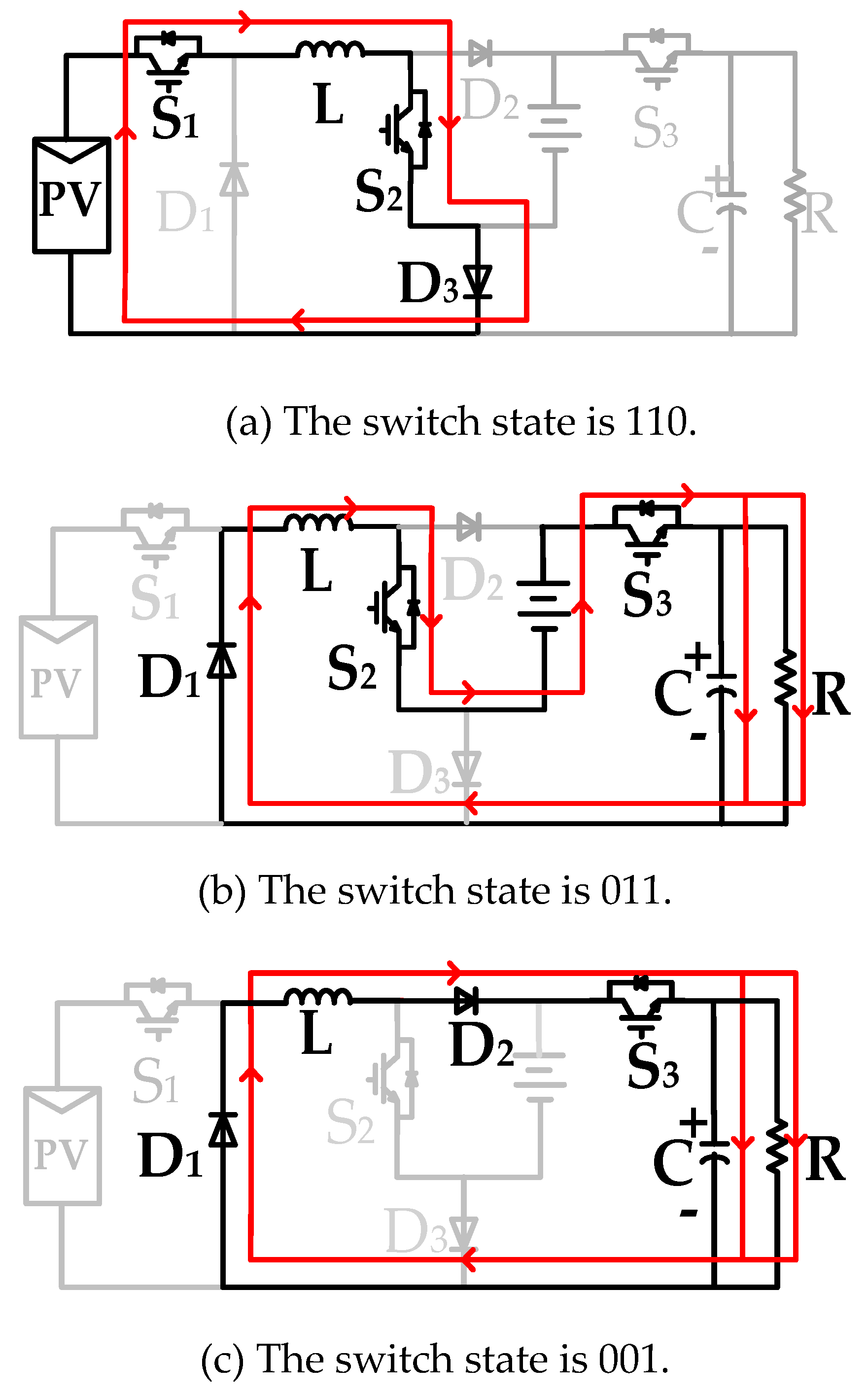
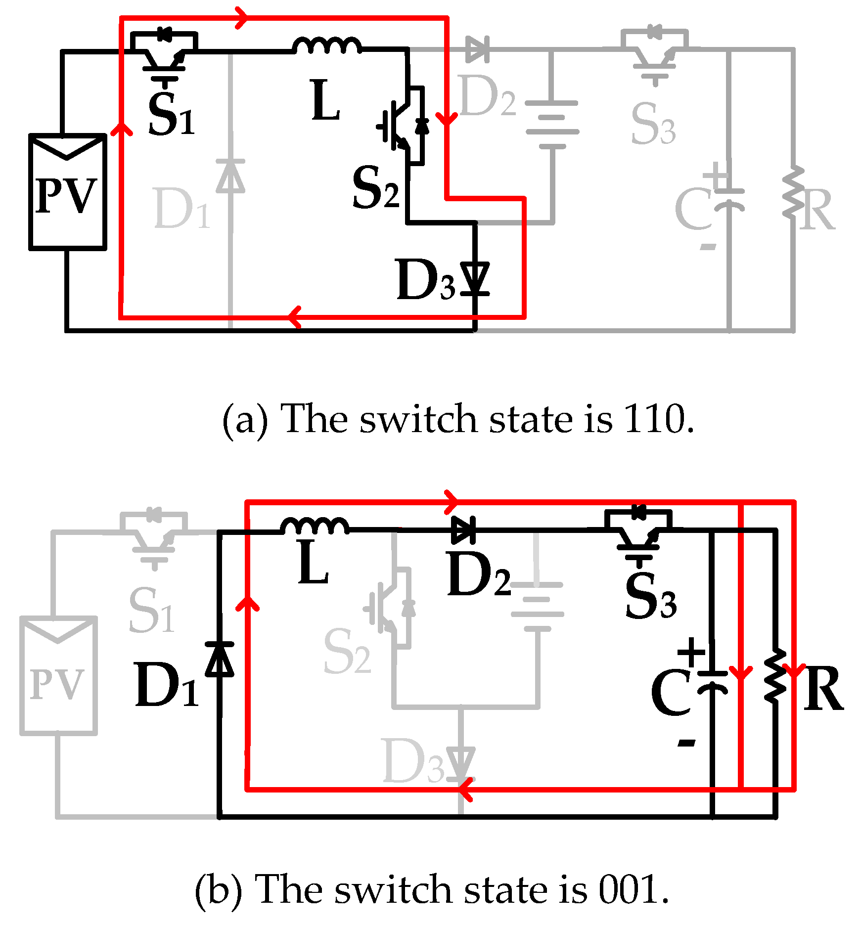
2.3.1. Working Status of TPC in DISO Mode

Figure 6 and Figure 7 show the DISO mode of the topology under the same working conditions, and its working state is (110→011→001). As shown in Figure 6 and Figure 7, in the period of Figure 6 [t0, t1] corresponding to the state of Figure 7a, the solar panel supplies power to inductor L. When the TPC operates in the period of Figure 6 [t1, t2] and state of Figure 7b, the switches S2 and S3 are in the on the state and the S1 is in the off state, the freewheeling diode D1 is turned on, and the power flow direction flows from the battery to the load side. When switch S2 is turned off, TPC operates during the period of Figure 6 [t2, t3], in the state of Figure 7c, inductor L delivers energy to the load. Thus, according to the Equations (4), (5) and (7), the Equations (13)–(16) can be obtained.
V in d 1 = V o ( 1 d 1 ) V b ( d 2 d 1 )
V in = V o ( 1 d 1 ) V b ( d 2 d 1 ) d 1
V b = V o ( 1 d 1 ) V in d 1 d 2 d 1
V o = V in d 1 + V b ( d 2 d 1 ) 1 d 1

2.3.2. Working Status of TPC in SISO Mode

Figure 8 and Figure 9 show the SISO mode of the topology under the same conditions. Taking the solar panel to transfer energy to the load, for example, its working state is (110→001). As shown in Figure 8 and Figure 9, in the period of Figure 8 [t0, t1] corresponding to the state of Figure 9a, the switches S1 and S2 are in an on state, the switch S3 is in an off state, the diode D3 is turned on, the solar panel transmits energy to the inductor, and the inductor L is charged. When the TPC operates in the period of Figure 8 [t1, t2] and the state of Figure 9b, the switches S1 and S2 are in the off state, S3 is in the on state, the freewheeling diode D1 is in the on the state, the inductor L is discharged to the load. Thus, according to Equations (4) and (5), Equations (17)–(19) can be obtained.
V o ( 1 d 1 ) = V in d 1
V in = 1 d 1 d 1 V o
V o = d 1 1 d 1 V in

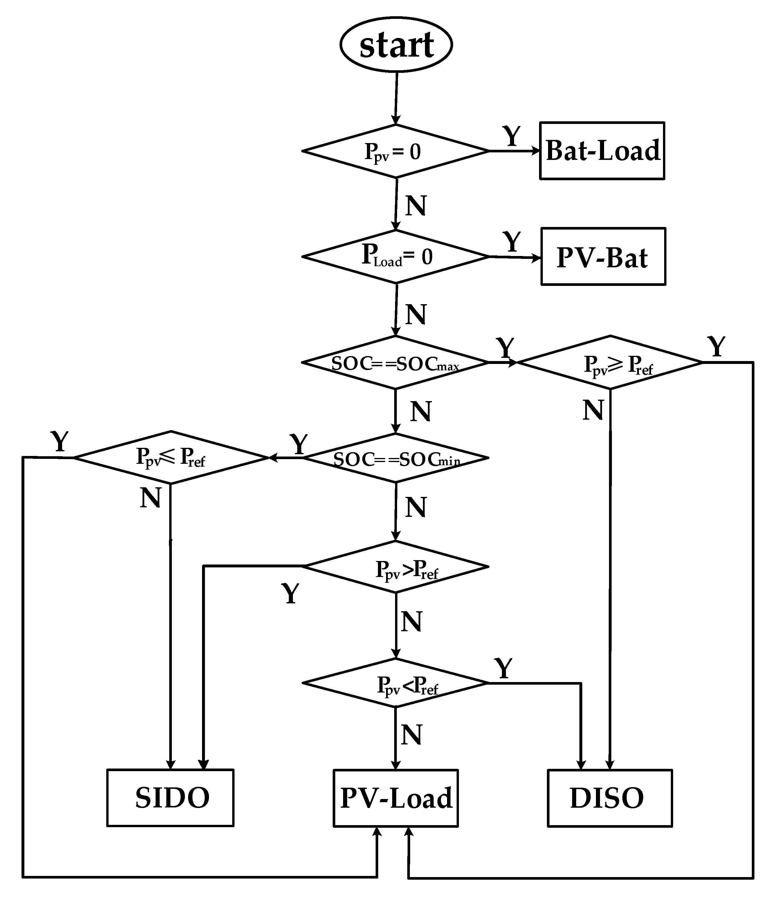
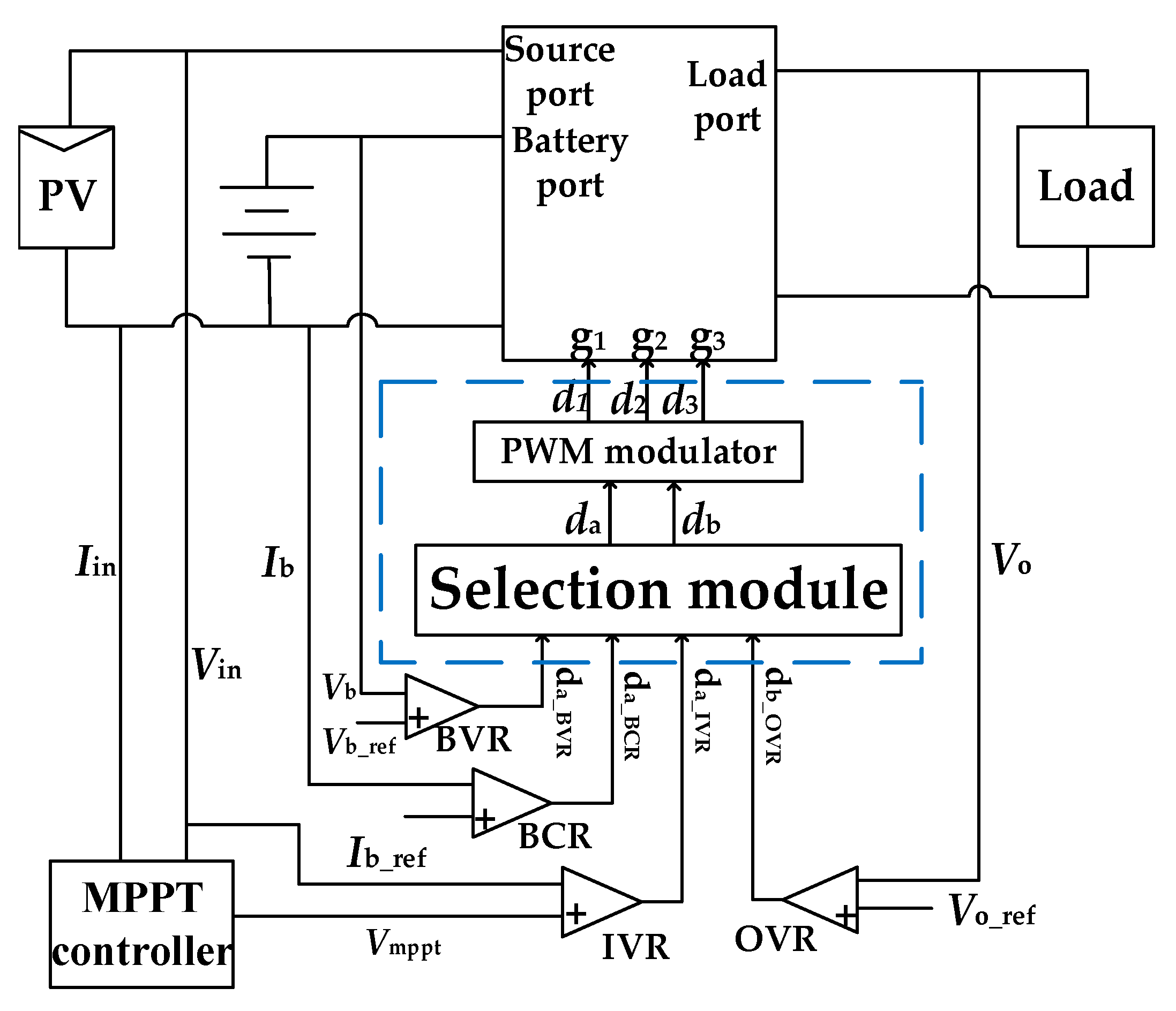
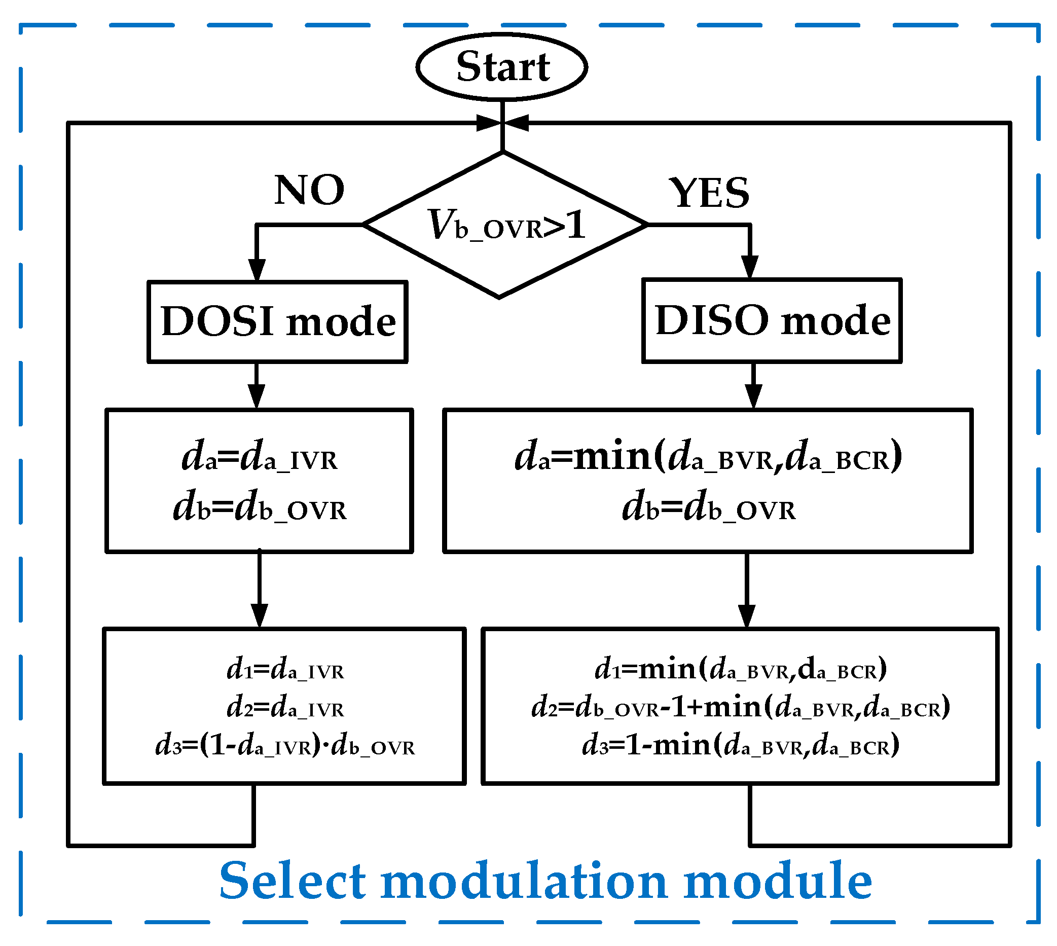
3. Three-Port Switching Boost Converter Control Strategy

The control block diagram of the topology circuit is shown in Figure 10. The control method includes four controllers. The input voltage regulation (IVR) controls the solar panel voltage through the PI regulator to the optimal operating voltage matched by the MPPT and output the duty cycle da_IVR. When the TPC is operating in the SIDO mode, da_IVR gains control over the duty cycle da. The battery voltage regulation (BVR) and the battery current regulation (BCR) are two parallel controllers for regulating the voltage and current across the battery. When the TPC operates in the DISO mode, the controller outputs one of the control signals da_BVR and da_BCR to obtain control of the duty ratio da. The output voltage regulation (OVR) controller is used to stabilize the output voltage of the system in the output control voltage loop. The output db_OVR of the OVR is also used to determine the operating mode of the TPC.
When the operating condition of the TPC is Vb > Vin > Vo, the working mode judging method is as shown in Figure 11. When db_OVR > 1, the TPC load side output power Po is large, the input power Pin provided by the solar panel is insufficient to meet the power demanded on the load side, the battery provides energy Pb as a supply, and the solar panel and the battery jointly transmit energy to the load. That is, TPC works in DISO mode. When the control signal 0 < db_OVR < 1 is output by the OVR, the energy Pin provided by the solar panel is higher than the energy Po required on the load side, the battery absorbs excess energy, and the solar panel simultaneously transfers energy to the battery and the load. That is, TPC works in SIDO mode. When the TPC switches between the two modes of operation, duty cycle da selects their minimum by comparing the IVR, BVR and BCR output signals. This avoids system oscillations due to transient changes in the duty cycle. When the TPC is operating in the DISO mode, control signals da_BVR or da_BCR are output by the parallel controller of the battery, the BVR or the BCR is small, and so the smaller value obtained by further comparison between the two obtains the control of the duty cycle da. When the TPC works in the SIDO mode of operation, da_IVR is the smallest and control is obtained for the duty cycle da. Therefore, the converter can judge the power flow of the TPC according to the output of the OVR, the battery is used to balance the system power, and the controller output signal is compared to enable the TPC to smoothly switch the mode.

4. Simulation and Experiment

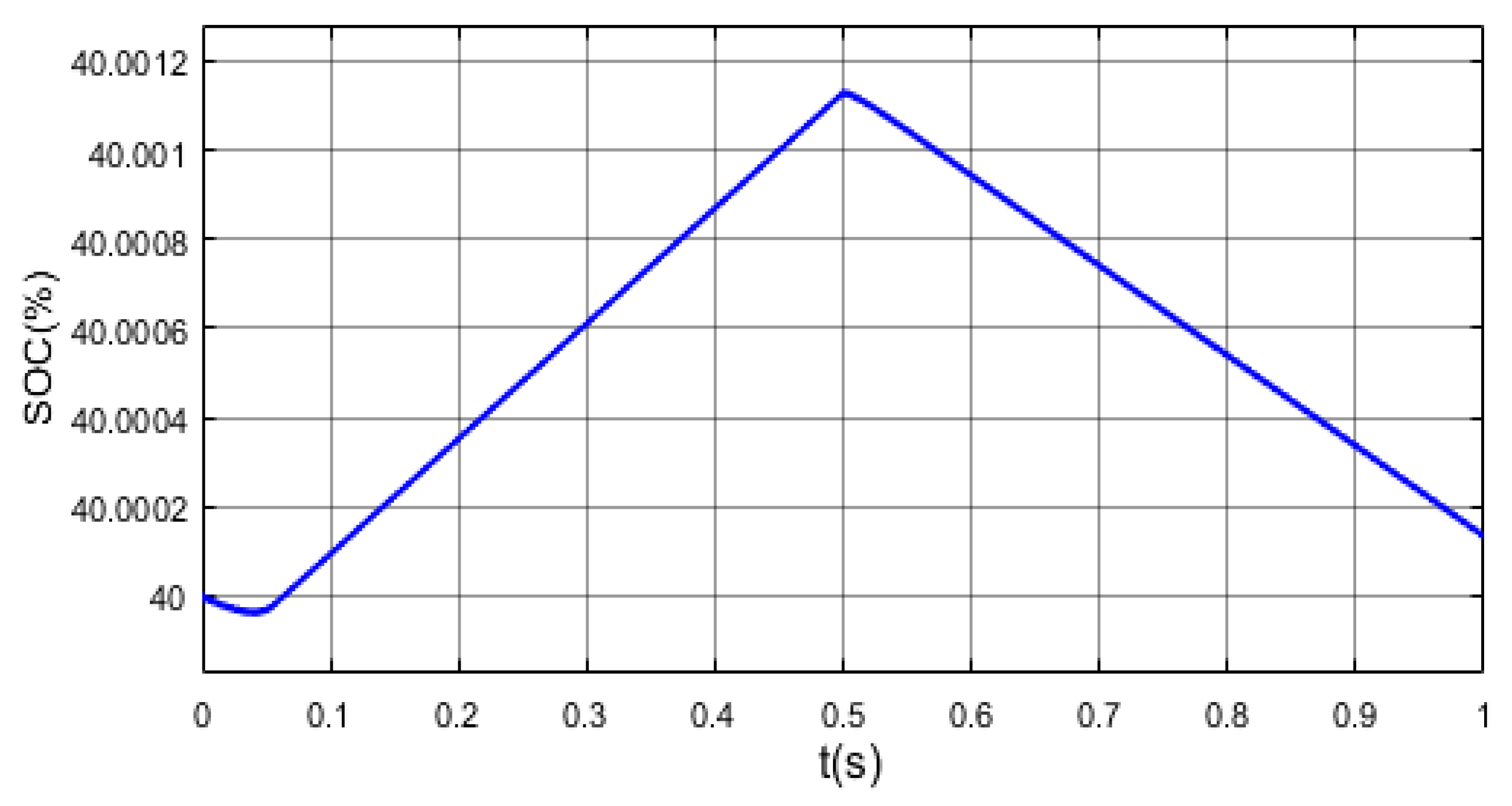
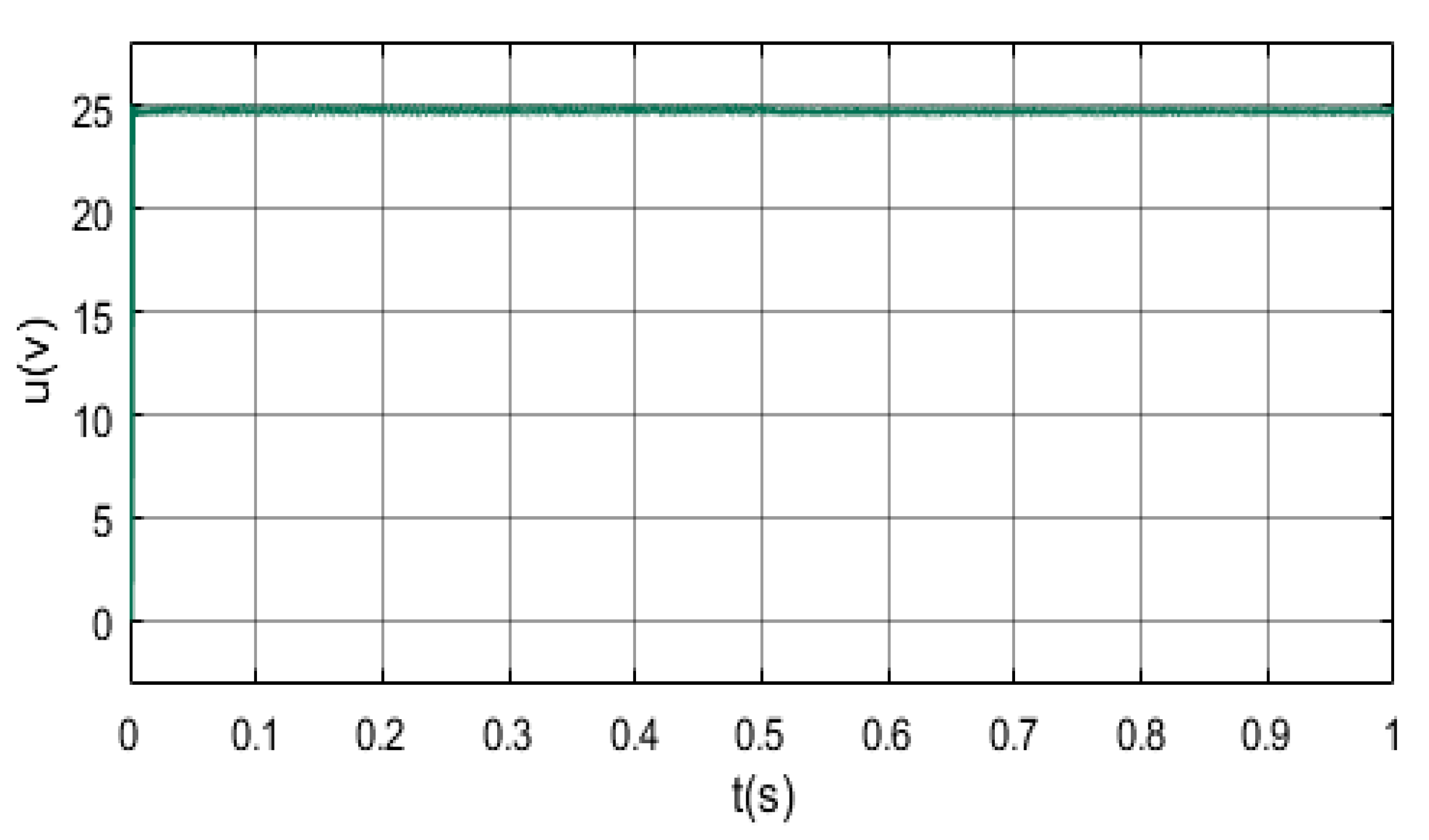
4.1. Simulation Results

The simulation was executed by MATLAB/Simulink and the simulation parameters were configured as follows: The battery voltage Vb is 60 V; the output voltage Vo is given as 25 V; the capacitance C is 560 μF; the inductance L is 2 mH; the maximum operating voltage Vm of the solar panel is 40 V; and the maximum working current Im is 5.56 A.
Figure 12 is the SOC curve of the battery. As can be seen from the figure, the battery power increases in 0–0.5s and the TPC works in SIDO mode; in 0.5–1s, the battery power decreases and the TPC switches from SIDO mode to DISO mode. Figure 13 shows the output of the system under the OVR control loop. It can be seen that in this process, the output voltage can be stabilized at a given 25 V level due to the role of the OVR controller.

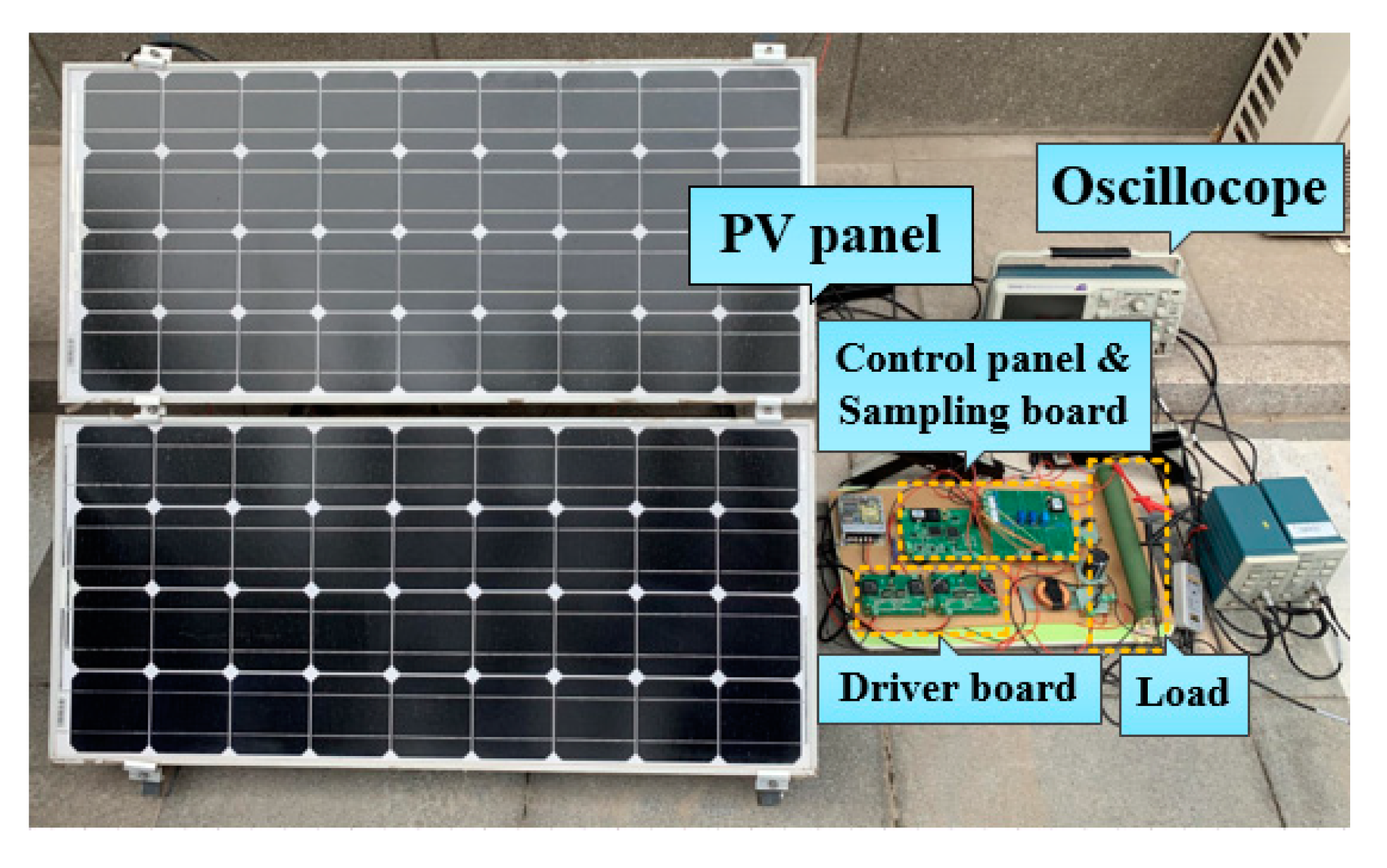
4.2. Experimental Results and Analysis

In order to verify the feasibility of the above control strategy, an experimental platform for constructing a three-port switching boost converter is shown in Figure 14, the specific parameters are as follows: The battery rated voltage Vb is 30.15 V, the output voltage Vo is 10 V, the load resistance R is 20–60 Ω, the capacitance C is 560 μF, the inductance L is 2 mH; the maximum operating voltage Vm of the solar panel is 20 V; and the maximum working current Im is 2.78 A. The prototype controller is implemented using the STM32F746 ARM kit., it is manufactured by STMicroelectronics (Geneva, Switzerland); The system’s switching frequency is set to 10 kHz. The power semiconductor used in the experiment: The MOSFETs are IRFPS37N50A manufactured by International Rectifier Corporation (El Segundo, CA, USA); the diodes are DSEI2 × 61-12B manufactured by IXYS (Milpitas, CA, USA).

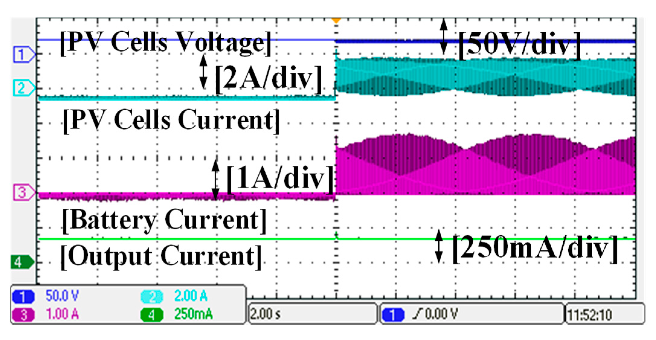
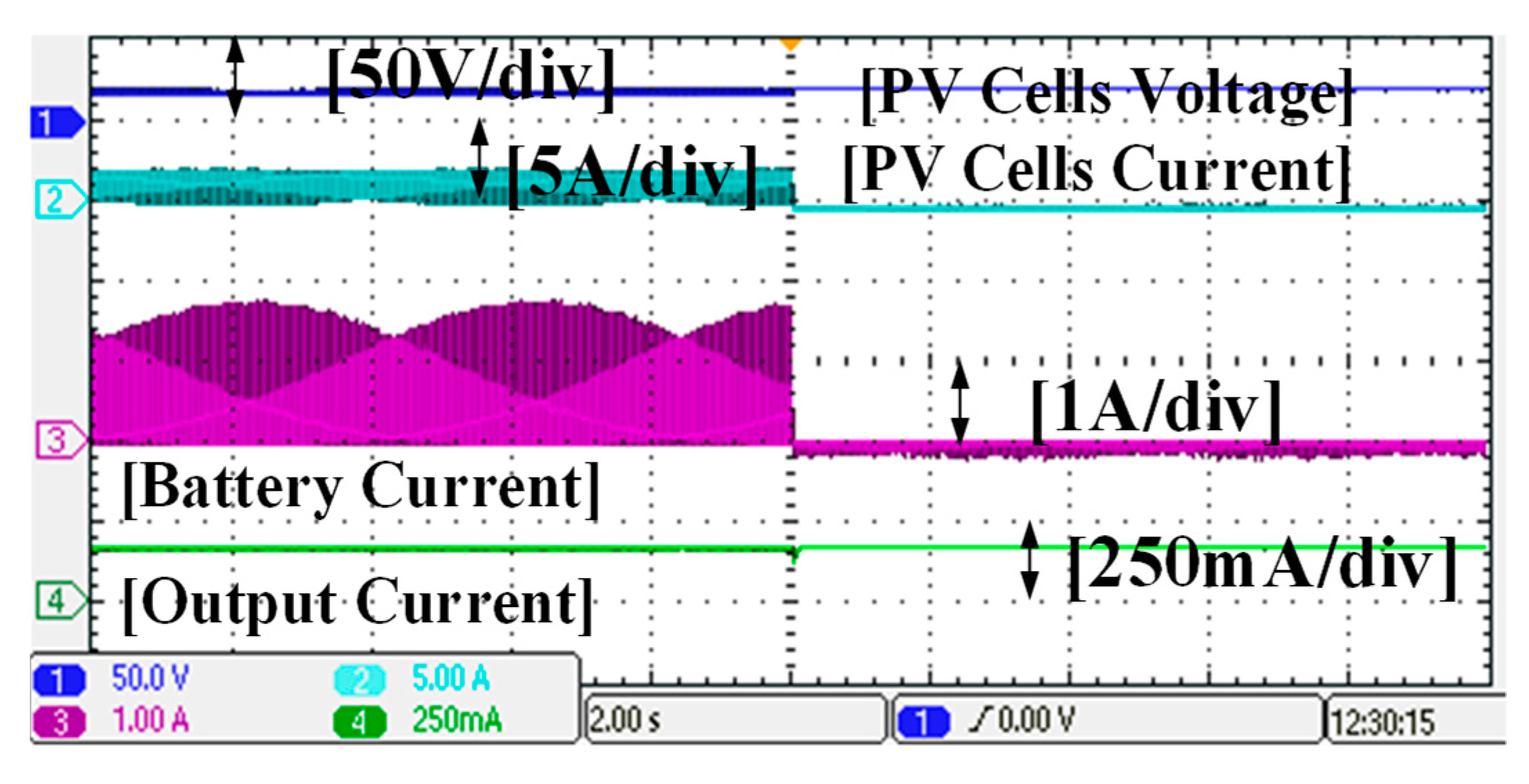
4.2.1. Three-Port Switching Boost Converter Power Flow Experiment

Figure 15 and Figure 16 show the steady-state operating waveforms of the TPC switching between two different operating modes when the illumination is sufficient. It can be seen that the solar panel works at the maximum power point to provide an input voltage Vin of 20 V and remains substantially constant. In DISO mode, the solar panel input current Iin is 0.15 A, the input power of the solar panel is 20 V × 0.15 A = 3 W, the battery output current Ib is 0.05 A, the output power of the battery is 1.26 W, and the load side output power is 3.796 W. Therefore, in DISO mode, the total input power of the system is 4.26 W and the total output power is 3.796 W. The efficiency of the system is 89.1%. In the SIDO mode, Iin is 1.8 A, the input power of the solar panel is 20 V × 1.8 = 36 W, the battery inflow current Ib is 114 A, and the input power of the battery is 28.86 W. The system output voltage is kept stable through the closed-loop adjustment of the OVR regulator and the load side output power is 3.796 W. Thus, in SIDO mode, the total input power is 36 W, the output power is 32.656 W. The efficiency of the system is 90.7%. As can be seen from Figure 15 and Figure 16, as the load power changes, the battery balances the system power, and the TPC smoothly transitions between the DISO mode and the SIDO mode, which is consistent with the above analysis of the operating principle.

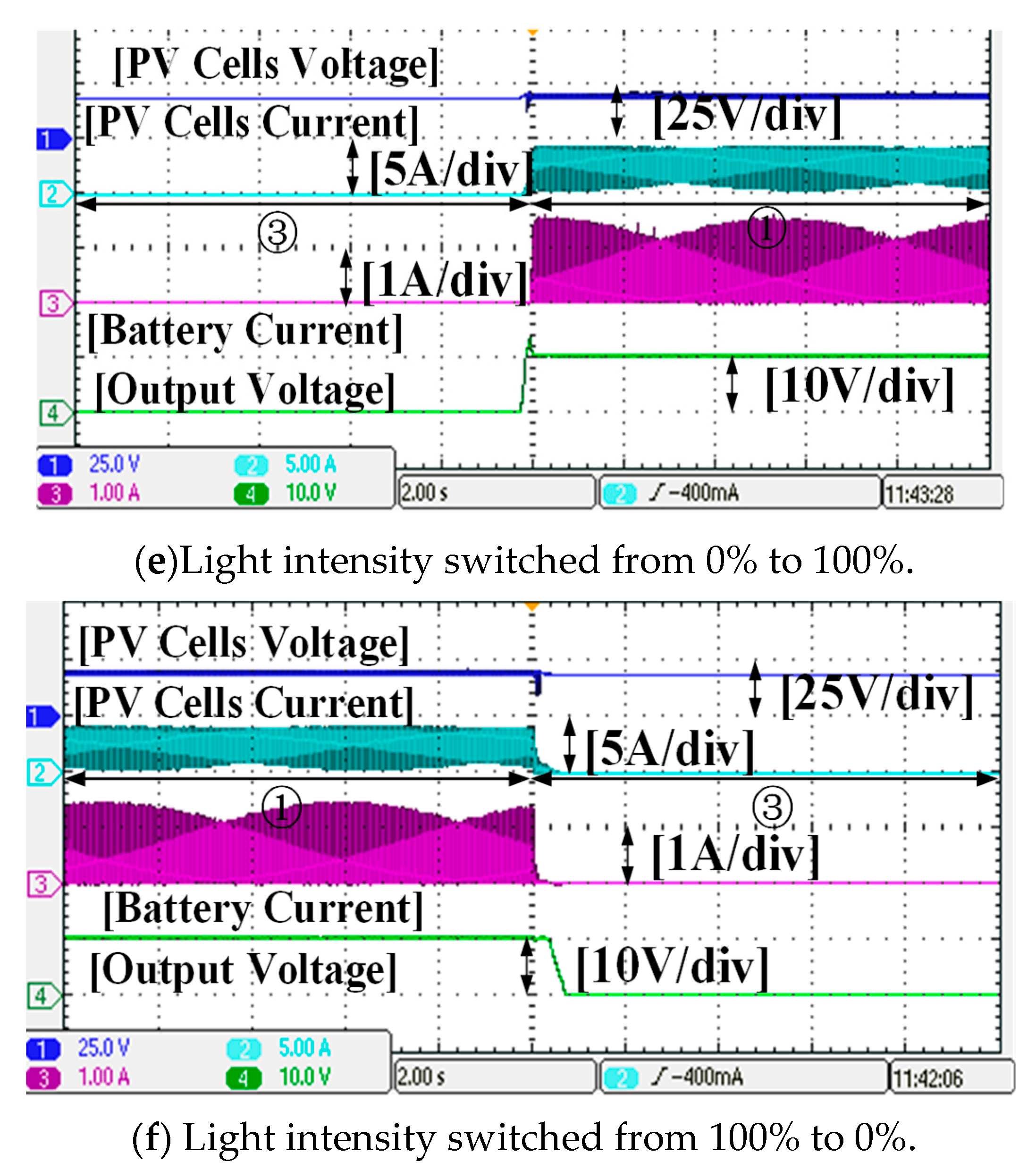
4.2.2. Maximum Power Point Tracking Experiment

Figure 17a–f show the steady-state operating waveforms of TPC operating in SIDO mode, switching between different illumination intensities. It can be seen that there are three states: 1. The solar panel is completely exposed to sunlight to obtain the largest possible light intensity. At this time, the solar panel current Iin is 2.5 A and the voltage Vin is 20 V, and the input power of solar panel is 2.5 A × 20 V = 50 W. They all work near the maximum power point, so that the solar panel power Pin reaches the maximum, the battery stable inflow current Ib is 0.5 A, the battery input power is 15 W, and the output voltage Vo is stable at 10 V. System load side output power is 24 W. 2. The solar panel receives about two-thirds of the light under normal conditions. It can be seen that the input voltage Vin is stable at around 20 V, the solar panel current Iin is reduced to 1.3 A, the solar panel power is reduced to 1.3 A × 20 V = 26 W, and the output voltage Vo is almost unchanged due to closed-loop control. In order to keep the output power unchanged, the battery inflow current decreases, the Ib is 0.03 A, and the battery input power is 0.9 W. The output power is 24 + 0.9 = 24.9 W. 3. Block all solar panels so that the solar panels do not receive light. The input voltage Vin of the solar panel is substantially unchanged at 20 V, almost no power flows to the load side, and the output voltage Vo is almost zero at this time. It can be obtained from the experimental results that the system can maintain stable operation during different light intensity switching processes.

5. Conclusions

This paper proposes a non-isolated three-port switching boost converter and applies it to photovoltaic systems. This converter has the following advantages: it combines the characteristics of the switching boost network, eliminating the power converter of the battery after the traditional energy storage system. Through the control of switches, the power flow management between the three ports is realized, which breaks the limitation of the voltage relationship between the ports. The TPC uses only one inductor, and the system structure is simple, which reduces the cost and the volume.
In addition, this paper applies the three-port switching boost converter to the photovoltaic system, realizes the dynamic tracking of the maximum power point of the system and realizes the smooth switching between the TPC working modes, and completes the theoretical analysis and experimental verification of the system power flow.

Author Contributions

Conceptualization, S.L., Y.G. and L.Y.; validation, S.L. and Y.G.; writing—original draft preparation, S.L. and Y.G.; writing—review and editing, S.L. and Y.G.

Funding

This research was funded by the National Natural Science Foundation of China, grant number 51807001.

Conflicts of Interest

The authors declare no conflict of interest.

References

  1. Zhou, Z.; Xiong, F.; Huang, B.; Xu, C.; Jiao, R.; Liao, B.; Yin, Z.; Li, J. Game-theoretical Energy Management for Energy Internet with Big Data-based Renewable Power Forecasting. IEEE Access 2017, 5, 5731–5746. [Google Scholar] [CrossRef]
  2. Rahbar, K.; Chai, C.C.; Zhang, R. Energy Cooperation Optimization in Microgrids with Renewable Energy Integration. IEEE Trans. Smart Grid 2016, 9, 1482–1493. [Google Scholar] [CrossRef]
  3. Sher, H.A.; Murtaza, A.F.; Noman, A.; Addoweesh, K.E.; Al-Haddad, K.; Chiaberge, M. A New Sensorless Hybrid MPPT Algorithm Based on Fractional Short-Circuit Current Measurement and P&O MPPT. IEEE Trans. Sustain. Energy 2015, 6, 1426–1434. [Google Scholar]
  4. Dallago, E.; Liberale, A.; Miotti, D.; Venchi, G. Direct MPPT algorithm for PV sources with only voltage measurements. IEEE Trans. Power Electron. 2015, 30, 6742–6750. [Google Scholar] [CrossRef]
  5. Chen, Y.M.; Liao, C.Y. A PV Micro-inverter with PV Current Decoupling Strategy. IEEE Trans. Power Electron. 2016, 32, 6544–6557. [Google Scholar]
  6. Zhu, H.; Zhang, D.; Athab, H.S.; Wu, B.; Gu, Y. PV Isolated Three-Port Converter and Energy-Balancing Control Method for PV-Battery Power Supply Applications. IEEE Trans. Ind. Electron. 2015, 62, 3595–3606. [Google Scholar] [CrossRef]
  7. Chen, K.; Tian, S.; Cheng, Y.; Bai, L. An Improved MPPT Controller for Photovoltaic System under Partial Shading Condition. IEEE Trans. Sustain. Energy 2014, 5, 978–985. [Google Scholar] [CrossRef]
  8. Jiang, Y.; Qahouq, J.A.A.; Haskew, T.A. Adaptive Step Size with Adaptive-Perturbation-Frequency Digital MPPT Controller for a Single-Sensor Photovoltaic Solar System. IEEE Trans. Power Electron. 2013, 28, 3195–3205. [Google Scholar] [CrossRef]
  9. De Souza, A.C.; Melo, F.C.; Oliveira, T.L.; Tavares, C.E. Performance Analysis of the Computational Implementation of a Simplified PV Model and MPPT Algorithm. IEEE Lat. Am. Trans. 2016, 14, 792–798. [Google Scholar] [CrossRef]
  10. Mishra, P.P.; Fathy, H.K. Achieving Self-Balancing by Design in Photovoltaic Energy Storage Systems. IEEE Trans. Control Syst. Technol. 2018, 29, 1–14. [Google Scholar] [CrossRef]
  11. Chien, L.J.; Chen, C.C.; Chen, J.F.; Hsieh, Y.P. Novel Three-Port Converter With High-Voltage Gain. IEEE Trans. Power Electron. 2014, 29, 4693–4703. [Google Scholar] [CrossRef]
  12. Zhu, H.; Zhang, D.; Zhang, B.; Zhou, Z. A Nonisolated Three-Port DC–DC Converter and Three-Domain Control Method for PV-Battery Power Systems. IEEE Trans. Ind. Electron. 2015, 62, 4937–4947. [Google Scholar] [CrossRef]
  13. Zhao, J.; Iu, H.H.; Fernando, T.; An, L.; Lu, D.D. Design of a non-isolated single-switch three-port DC-DC converter for standalone PV-battery power system. In Proceedings of the 2015 IEEE International Symposium on Circuits and Systems (ISCAS), Lisbon, Portugal, 24–27 May 2015. [Google Scholar]
  14. Zeng, J.; Qiao, W.; Qu, L. Modeling and control of a three-port DC-DC converter for PV-battery systems. In Proceedings of the Applied Power Electronics Conference and Exposition (APEC), Charlotte, NC, USA, 15–19 March 2015; pp. 1768–1773. [Google Scholar]
  15. Wu, H.; Wang, J.; Liu, T.; Yang, T.; Xing, Y. Modified SVPWM Controlled Three-Port Three-Phase AC-DC Converters with Reduced Power Conversion Stages for Wide Voltage Range Applications. IEEE Trans. Power Electron. 2017, 33, 6672–6686. [Google Scholar] [CrossRef]
  16. Faraji, R.; Farzanehfard, H. Soft-switched Non-Isolated High Step-up Three-port DC-DC converter for Hybrid Energy Systems. IEEE Trans. Power Electron. 2018, 33, 10101–10111. [Google Scholar] [CrossRef]
  17. Wu, H.; Sun, K.; Ding, S.; Xing, Y. Topology Derivation of Nonisolated Three-Port DC-DC Converters from DIC and DOC. IEEE Trans. Power Electron. 2013, 28, 3297–3307. [Google Scholar] [CrossRef]
  18. Wu, H.; Wong, S.C.; Chi, K.T.; Chen, Q. Control and Modulation of Bidirectional Single-Phase AC–DC Three-Phase-Leg SPWM Converters with Active Power Decoupling and Minimal Storage Capacitance. IEEE Trans. Power Electron. 2016, 31, 4226–4240. [Google Scholar] [CrossRef]
  19. Lu, Y.; Sun, K.; Wu, H.; Dong, X.; Xing, Y. A Three-port Converter Based Distributed DC Grid-connected PV System with Autonomous Output Voltage-Sharing Control. IEEE Trans. Power Electron. 2018, 34, 325–339. [Google Scholar] [CrossRef]
  20. Su, G.J.; Tang, L. A Reduced-Part, Triple-Voltage DC–DC Converter for EV/HEV Power Management. IEEE Trans. Power Electron. 2009, 24, 2406–2410. [Google Scholar]
  21. Wu, H.; Zhang, J.; Qin, X.; Mu, T.; Xing, Y. Secondary-Side-Regulated Soft-Switching Full-Bridge Three-Port Converter Based on Bridgeless Boost Rectifier and Bidirectional Converter for Multiple Energy Interface. IEEE Trans. Power Electron. 2016, 31, 4847–4860. [Google Scholar] [CrossRef]
  22. Hu, Y.; Xiao, W.; Cao, W.; Ji, B.; Morrow, D.J. Three-Port DC–DC Converter for Stand-Alone Photovoltaic Systems. IEEE Trans. Power Electron. 2014, 30, 3068–3076. [Google Scholar] [CrossRef]
  23. Chen, Y.; Wen, G.; Peng, L.; Kang, Y.; Chen, J. A family of cost-efficient non-isaolated single-inductor three-port converters for low power stand-alone renewable power applications. In Proceedings of the 2013 Twenty-Eighth Annual IEEE Applied Power Electronics Conference and Exposition (APEC), Long Beach, CA, USA, 17–21 March 2013. [Google Scholar]
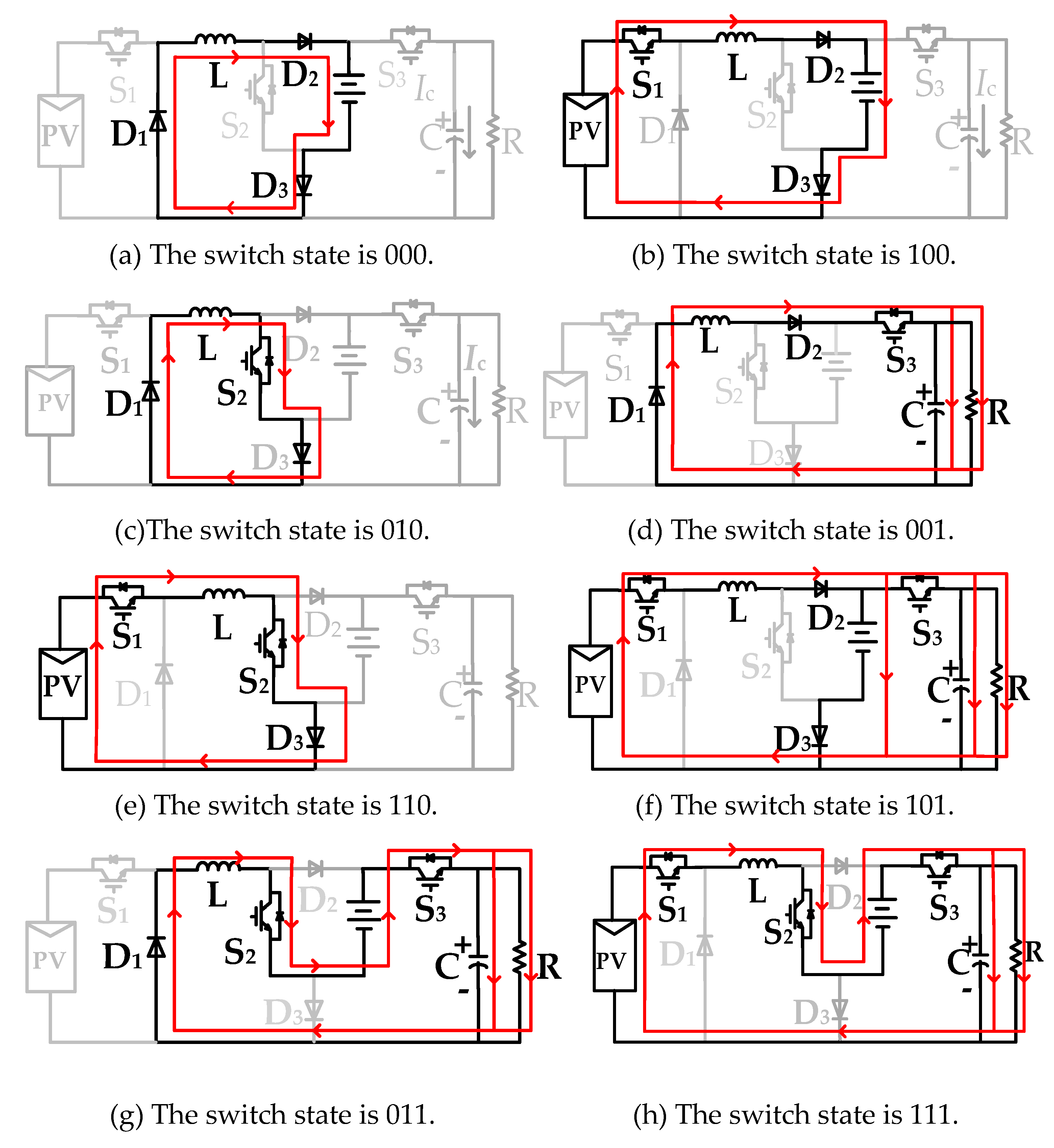
Figure 1. Buck–boost integrated dual active bridge three-port DC–DC converter.
Electronics 08 00746 g001
Figure 2. Topological working states.
Electronics 08 00746 g002
Figure 3. Topological working state.
Electronics 08 00746 g003
Figure 4. Waveforms in single input dual output (SIDO) mode.
Electronics 08 00746 g004
Figure 5. Working states of SIDO mode.
Electronics 08 00746 g005aElectronics 08 00746 g005b
Figure 6. Waveforms in dual input single output (DISO) mode.
Electronics 08 00746 g006
Figure 7. Working states of DISO mode.
Electronics 08 00746 g007
Figure 8. Waveforms in single input single output (SISO) mode.
Electronics 08 00746 g008
Figure 9. Working states of SISO mode.
Electronics 08 00746 g009
Figure 10. Control block diagram.
Electronics 08 00746 g010
Figure 11. Selection modulation module diagram.
Electronics 08 00746 g011
Figure 12. Curve of battery.
Electronics 08 00746 g012
Figure 13. Output voltage waveform.
Electronics 08 00746 g013
Figure 14. The experimental platform.
Electronics 08 00746 g014
Figure 15. DISO mode switches to SIDO mode.
Electronics 08 00746 g015
Figure 16. SIDO mode switches to DISO mode.
Electronics 08 00746 g016
Figure 17. Maximum power point tracking experimental waveform.
Electronics 08 00746 g017aElectronics 08 00746 g017b
Table 1. Working state combination.
abcdefgh
Switch status000100010001110101011111
Number of ports flowing through12011223

