1. Introduction
One inherent defect in wireless communication systems is their lack of security owing to the broadcast nature of wireless channels. To enable secure transmission over wireless channels, physical layer security schemes exploit the physical characteristics of wireless channels without relying on cryptography [
1,
2]. From an information-theoretic viewpoint, secrecy capacity is defined as the maximum achievable secrecy rate at which a source can send a confidential message to a destination without being overheard by eavesdroppers. To enlarge the secrecy rate in wireless channels, various approaches have been studied to exploit multiple-antenna techniques [
3,
4], relay-assisted secure transmission schemes [
5], node cooperation strategies [
6,
7,
8], and dirty paper coding (DPC) based information embedding approaches [
9], where global channel state information (CSI) is assumed. In [
10,
11], secure communication with delayed CSI has been investigated from a secure degrees of freedom perspective.
To enhance wireless physical layer security even when global CSI is not available, beamforming with artificial noise has been widely investigated [
12,
13]. In [
14], the artificial noise is placed in the null space of the destination’s channel to prevent artificial noise from leaking to the destination. Further, to decide what portion of available transmit power is allocated for sending artificial noise to interrupt eavesdroppers, the statistics of the eavesdroppers’ channels are exploited at the source in [
15]. Since the exact CSI of the destination’s channel is required for the above techniques, the leakage of artificial noise to the destination is inevitable when the destination’s channel estimation is imperfect [
16].
In this work, we propose a beamformer design scheme exploiting partial CSI in millimeter wave (mmWave) channels. The partial CSI exploited in this work is the range of angle-of-departure (AOD). We assume that even though the AOD of a dominant multipath between the BS and each node is not exactly known to the BS, it falls within a certain range and the AOD ranges of the destination and the eavesdroppers are available at the BS. Note that compound wiretap channels in [
17] assume that the destination’s channel is perfectly known, while the eavesdroppers’ channels belong to a known set of channels characterized by partial CSI such as maximum channel gain. The AOD ranges for the eavesdroppers in this work can be considered as the known set of channels defined in compound wiretap channels. While the compound wiretap channel assumes the perfect knowledge on the destination’s channel, we consider only the AOD range for the destination. Using the AOD range information, we design a transmit beamformer for sending confidential messages based on array pattern synthesis using semidefinite programming [
18].
Recently, array pattern synthesis has been utilized to design cluster beamformers in non-orthogonal multiple access systems. In [
19], the cluster beamformer is designed to minimize inter-cluster interference under the constraint of maintaining the beamforming gain to the desired cluster exceeding a given threshold. Unlike the previous study in [
19], we focus on maximizing the ratio of the beamforming gains at the destination and the eavesdroppers by considering that the secrecy rate is determined by the difference between rates at the destination and the eavesdroppers. Using numerical results, we show that the proposed approach using AOD ranges is efficient for physical layer security when the array antenna size is large and the channel estimation error is critical.
2. System Model and Secrecy Rate Evaluation
Consider a BS that sends secure information to a destination in the presence of
I non-colluding eavesdroppers [
20]. In a non-colluding scenario, each eavesdropper works independently and decodes the message solely based on its own observation. On the other hand, a colluding scenario considers that multiple eavesdroppers share their observations and jointly decode the message assuming the existence of communication links between eavesdroppers, which represents a worst-case scenario. The colluding eavesdroppers can be treated as a single eavesdropper with multiple antennas in [
3]. Even though we propose a beamformer design scheme assuming non-colluding eavesdroppers, the secrecy rate achieved by the proposed beamformer is also evaluated in a colluding scenario, which will be presented in
Section 4.
We assume that the BS has an antenna array with
N antenna elements, whereas the destination
D and each eavesdropper
are equipped with a single antenna. Let
and
be the received baseband signals at
D and
, respectively. The received signals can be expressed as
where
and
are vectors containing the complex channel coefficients from the BS to
D and
, respectively. Further,
denotes a transmit beamformer and
s is the secure information with unit power. The noises
and
are assumed to be complex additive white Gaussian with zero-mean and variance
. Here, we can compute the rates at
D and
as
respectively. Then, the achievable secrecy rate can be expressed as
[
21].
Assuming global CSI is available at the BS, we can find the optimal transmit beamformer, which maximizes the achievable secrecy rate, by solving the following optimization problem:
where
denotes the conjugated transpose and
P is the transmit power of the BS. The detailed derivation for solving (
3) is highlighted in the
Appendix. It is noteworthy that the beamformer design problem to minimize the transmit power with the secrecy rate constraint is also considered in [
21].
Let us consider a uniform planar array (UPA) at the BS, where
N antenna elements are placed in a two-dimensional grid pattern. When channel reciprocity is available, the channels from the BS to
D and
can be expressed as [
22]
respectively, where
and
are complex Gaussian vectors with zero mean and covariance matrices
and
, respectively. Furthermore,
denotes the number of multipaths between the BS and
D,
is the number of multipaths between the BS and
, and
and
denote the average power gain for each radio path. The
k-th columns of the matrix
and the matrix
are given as the steering vectors
and
, respectively. Here, the
n-th entries of
and
are defined as
and
, respectively, where
and
denote the location of the
n-th antenna element in wavelengths, which can be arbitrary but fixed and known, and
Here, and denote the AOD of the k-th multipath from D to the BS and from to the BS, respectively.
Considering the directional characteristics of mmWave channels and their poor scattering environments [
23], we assume that
and
for dominant radio paths are within certain AOD regions
and
in the horizontal and vertical (
u-
v) domain, respectively, and
and
are mutually exclusive. The AODs of the other multipaths, which are much weaker than the dominant multipath, are assumed to be unknown and distributed randomly in the
u-
v domain.
3. Secrecy Rate Maximization via Array Pattern Synthesis
Our approach to designing
with
and
is based on antenna pattern nulling to maximize the ratio between the minimum radiation to
and the maximum radiation to
. Considering only the dominant radio path, we approximate the objective function in (
3) as
. Note that
and
can be determined only when
and
are given. Since only the partial CSI
and
are available, we assume that the average power gain for the dominant radio path to noise ratio is the same for
D and
(i.e.,
) and consider a worst-case scenario given as
where
and the
n-th entry of the steering vector
is given as
. Let us rewrite (
6) as
where
. Note that (
7) can be rewritten as
It is obvious that (
8) is equivalent to
where
, tr(.) denotes the trace operation, and
indicates that
is a Hermitian positive semidefinite matrix.
To solve (
9), we first ignore the rank constraint based on semidefinite relaxation [
24]. Then, the problem becomes quasi-convex. It is noteworthy that all the inequality constraints in (
9) are convex [
25]. We can solve this quasi-convex problem using the bisection technique [
25,
26]. In detail, let us first consider the following convex feasibility problem for any given value of
:
By using a semidefinite program solver such as SeDuMi [
27] and Yalmip [
28], we can check the feasibility of (
10). The infeasibility of (
10) indicates that the given
cannot be achieved, even though we ignored the rank constraint. Then, we conclude that the maximum value of
, denoted as
, is less than the given
[
26]. If (
10) is feasible and the solution of (
10), denoted as
,
, and
, can be obtained, we should confirm that
is of rank one because the rank constraint is ignored in our problem. When
is of rank one, the given
can be achieved with the principal eigenvector of
. In this case, we conclude that
.
If the rank of
is higher than one, we have to determine whether any other rank-one solution to achieve the given
exists or not. Here, the penalty function method (PFM) in [
7] is adopted. Using
,
, and
, we first set
and perform the initialization step of the PFM. The initialization step of the PFM can provide
with
. Then,
is used as a starting point for the optimization step of the PFM. Both the initialization and optimization steps are iterative processes. At the
j-th iteration, both steps solve the following semidefinite programming problem:
where
and
are the maximum eigenvalue and the corresponding eigenvector of
. If we obtain a rank-one solution via the PFM for the given
, we conclude that
. When a rank-one solution is not available even though the PFM is performed, we conclude
.
Using the above results, we exploit the bisection technique with the initial interval
, which is assumed to include
. At the midpoint of the interval
, (
10) is solved as we described above. If it is infeasible, we update the upper bound of the interval as
. If it is feasible, we confirm whether the rank of
is one or not. The lower bound of the interval is updated as
when
is of rank one. Otherwise, the PFM is performed whether a rank-one solution for the given
exists or not. If the solution provided by the PFM is of rank one, the lower bound of the interval is updated as
. Otherwise, we update
. The above process is performed again for the updated interval, until the width of the interval is small enough (i.e.,
, where
is the desired accuracy). Since the initial interval is halved at each iteration,
iterations are required [
29]. As commented in [
7], we also found that the above process can always provide a rank-one solution in our simulations.
For numerical implementations, the constraints
and
in (
10) are approximated as
where
and
denote the sample points in
and
, respectively [
30]. When the numbers of the sample points in
and
are given as
and
, we have to solve (
10) with a matrix variable of size
, 2 nonnegative variables, and
linear constraints at each iteration of the bisection process. Interior point methods will take
iterations, where
represents the solution accuracy at the algorithm’s termination, and each iteration requires at most
arithmetic operations [
29]. Further, at each iteration of the PFM, we solve (
11), which will take
iterations and each iteration requires at most
arithmetic operations [
7].
4. Numerical Evaluation
In this section, we present numerical results to verify the secrecy rate performance of the proposed scheme. For simulation simplicity, we assume that
is a circle in the
u-
v domain given as
where
and
are the center and the radius of the circle, respectively. For each channel realization,
for a dominant path is randomly chosen within
, while
with
are randomly chosen in the whole
u-
v domain.
is also assumed to be a circle in the
u-
v domain with a center of
and radius of
.
is randomly chosen within
, while
with
are randomly chosen in the whole
u-
v domain. Note that the proposed scheme can be adopted for arbitrary shapes of
and
.
In the following results, we fix
,
,
, and
. Without loss of generality, we set
and consider a UPA with
antenna elements (i.e.,
), where each element is uniformly spaced by half a wavelength. The far field radiated by the planar array can be expressed as
[
30], where
is the radiation pattern of the
n-th antenna element. The
n-th antenna element is fed by
, which denotes the
n-th entry of
. In our simulation, we assume isotropic antenna elements with
[
30]. Let us refer to
as the beamforming gain of the antenna array.
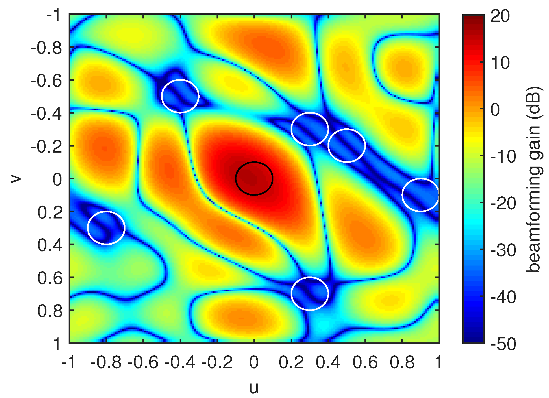
Let us consider a scenario where
eavesdroppers exist in the network and each
is given as in
Table 1. Here, we verify the validity of the proposed beamformer from the viewpoint of the beamforming gain of the planar array. For illustration purposes, we present the beamforming gain of the transmit beamformer obtained by the proposed scheme for this scenario when
in
Figure 1. The interior of the black circle is
, whereas the interior of the white circle denotes
. We found that the proposed beamformer provides
dB of the minimum beamforming gain in
and
dB of the maximum beamforming gain in
. From the simulation results, we found that the ratio between the minimum beamforming gain in
and the maximum beamforming gain in
increases with increasing
.
In
Appendix A, we derived the transmit beamformer for global CSI. Further, to investigate the impact of imperfect CSI, we assumed that the imperfect channel coefficients
and
are used instead of the exact channel coefficients
and
, where
and
, respectively. Here, each entry of
and
is assumed to be independent and identically distributed complex Gaussian with zero mean and
variance. We computed the transmit beamformer as in the
Appendix A by replacing
and
with the imperfect CSI
and
, respectively.
In
Figure 2, we compare the secrecy rate achieved by the proposed scheme and that with imperfect CSI for different values of
. We set
and consider that
,
, and
, which indicate that the second and third multipaths are 10 dB and 15 dB weaker than the dominant multipath, respectively [
23].
indicates the exact CSI. As expected, the secrecy rate for imperfect CSI decreases with an increase of
. Note that the secrecy rate performance of the proposed scheme is independent of
. It is observed that
at which the secrecy rate with imperfect CSI is better than that of the proposed scheme decreases as
increases. This indicates that the proposed scheme is efficient when the size of the antenna array is large and the channel estimation error becomes critical.
As described above, we consider that only the dominant path is within the given AOD region and the other multipaths are randomly distributed. It is expected that the other multipaths with AODs outside the given AOD region degrade the secrecy rate performance of the proposed scheme. In order to investigate the impact of the other multipaths, we evaluate the secrecy rate of the proposed scheme for different numbers of multipaths as shown in
Figure 3. For
, we consider only the dominant path with
, whose AOD is within the given AOD region. Note that
is optimal for the proposed scheme. For
, the second path is added with
, which is 10 dB weaker than the dominant path. For
, we use the same setting for
and
as in
Figure 2. When
, we add the multipaths which are 15 dB weaker than the dominant path. As expected, the secrecy rate performance of the proposed scheme degrades with an increase of
K. In particular, the gap between the secrecy rates with
and 2 is remarkable. For
, it is found that the secrecy rate with
is about 76% of that with
. However, the secrecy rate is shown to decrease slightly when
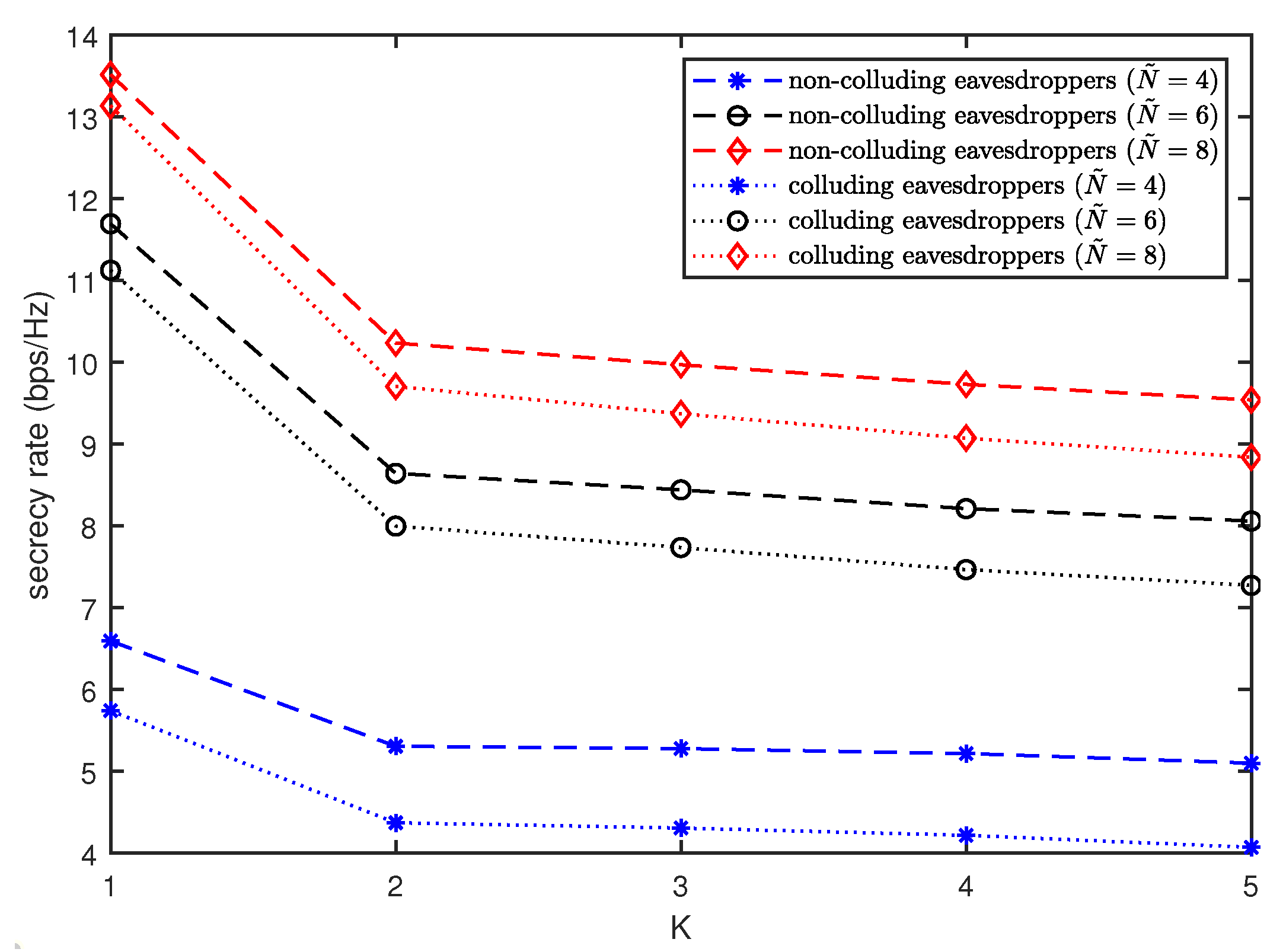
.
Figure 3 also presents the secrecy rate achieved by the proposed scheme in a colluding scenario. The rate at the colluding eavesdroppers can be given as
, where
[
3] and the achievable secrecy rate is computed as
. Since the proposed beamformer minimizes the beamforming gains to all eavesdroppers as shown in
Figure 1, the proposed scheme is also effective in a colluding scenario. In
Figure 3, the secrecy rate in a colluding scenario is observed to be worse than that in a non-colluding scenario. However, it is noteworthy that the gap between them reduces as
increases.


