1. Introduction
Internet of Things (IoT) is designed to attach a small communicating device with everything that we want to monitor or control using the Internet. The core of IoT networks consist of two types of devices: (a) sensors that collect the context data; and (b) actuators that receive commands to control the environment. IoT is mainly focused on the connectivity of things (daily life objects with attached sensors or actuators) to the Internet so that users can remotely monitor and control a particular activity or device. IoT systems have tremendous capabilities and applications [
1]. In the recent past, many giant manufacturing and development organizations have invested in this technology to realize its potential. Many projects are initiated to develop diverse IoT applications for many real-world problems and conduct research in various directions to address different aspects of IoT based systems along with associated challenges of security, authentication and authorization [
2], and identification of compromised nodes [
3].
To facilitate access and control of IoT devices in the cyber world, the concept of virtualization is introduced which provides a flexible interface to manipulate and interact with physical IoT devices [
4]. IoT devices are represented by virtual objects in the cyber world that provide flexible connectivity between sensors and actuators in the cyber world [
5]. Besides flexibility, virtualization also helps in resources’ seamless duplication and sharing across diverse domains [
6]. Many existing systems provide virtualization services for physical devices by creating its virtual object (VO). Later, VOs are combined to compose services that can be used to build various applications [
7,
8]. The virtual world is also known as the cyber world and the complete system is then referred to as a Cyber-Physical System (CPS) designed for physical world observation and control through the virtual world in IoT environments.
Usually, connectivity among devices is maintained in the network via routing tables. Routing tables provide an efficient and fast way for packet forwarding, but they are rigid. Making on-demand changes in routing tables is not easy, and hence the concept of Software Defined Networking (SDN) is introduced to separate network control and data plans [
9]. However, SDN requires networking devices to perform specific complex operations and protocols that are not supported by constrained IoT devices. For instance, OpenFlow protocol is commonly used by SDN controllers to update flow entries in networking devices for on-demand traffic management. Several research studies can be found in the literature regarding the development of programmable SDN infrastructure for enabling the IoT ecosystem [
10]. However, IoT devices are resources constrained in terms of memory and computation and provisioning support for OpenFlow like protocols will result in performance degradation.
Cloud computing technologies are aimed at provisioning stable and shared computational and storage resources to diverse users and applications [
11]. With the advent of this technology, end users can have a complete computer system online as per their desired specification and budget limitation in the form of a virtual machine. In many application scenarios, virtual machines’ instances launched on a cloud platform need to communicate with one another and soon virtual networks among the virtual machines will be created through virtual switches and virtual routers. After creating virtual networks in the cyber world, the functionalities of other essential networking devices such as intrusion detection devices, load balancers, firewalls, etc. were also virtualized in the form of network function virtualization (NFV). NFV framework requires three components: (a) software implementation of network function; (b) infrastructure for the deployment of virtualized network function; and (c) management and orchestration framework for virtualized network function. The conventional product development life cycle requires rigorous designing, testing, and standardization before release, which was very costly and time-consuming. NFV has brought a revolution in product development as it can quickly be deployed, tested in the real environment and easily upgraded when required.
Previously, most of the studies were focused on sensors virtualization in a cloud environment. All of the data collection and processing operations on connected virtual objects were handled in applications logic, and there was no such need for virtual network formation. However, with the advent of IoT, two types of devices are connected, i.e., sensors and actuators. The major difference between pure sensor network based and IoT based applications is that usually sensor-based applications are used for monitoring and analysis only, whereas IoT based applications are used for process automation. In IoT based applications, after careful analysis of sensing data through simple rule-based schemes or advanced machine learning algorithms, commands are sent to associated actuating devices to perform desired operations. In other words, there exists somehow a linkage or network among sensing and actuating devices. Traditionally, a configuration for the establishment of this network was either done in physical IoT devices or at the application layer as shown in
Figure 1a,b, respectively.
It is very difficult to change network settings in IoT devices and we have to physically or remotely access each device and then make desired modification. With a growing number of connected IoT devices, it has become impossible to make changes in individual IoT devices. Network setting at the application layer requires full control access to corresponding IoT devices, which is normally possible when the devices and application belong to the same owner. However, this approach is not favorable for sharing the underlying physical IoT network infrastructure. After IoT devices’ virtualization in a cloud environment, we can easily update and replicate virtual objects to seamlessly share a single IoT device among many dependent applications. As the virtual objects reside in the cloud infrastructure, virtual IoT networks can therefore be established among related virtual objects in the cloud environment. This paper presents the concept of virtualized IoT network formation over the cloud environment among connected IoT devices. To the best of our knowledge, there is no study published in the literature related to virtual IoT network formation among virtualized IoT devices and hence the subject matter of this paper. Recent development in various networking and cloud infrastructure technologies enabled us to explore the concept of IoT network virtualization.
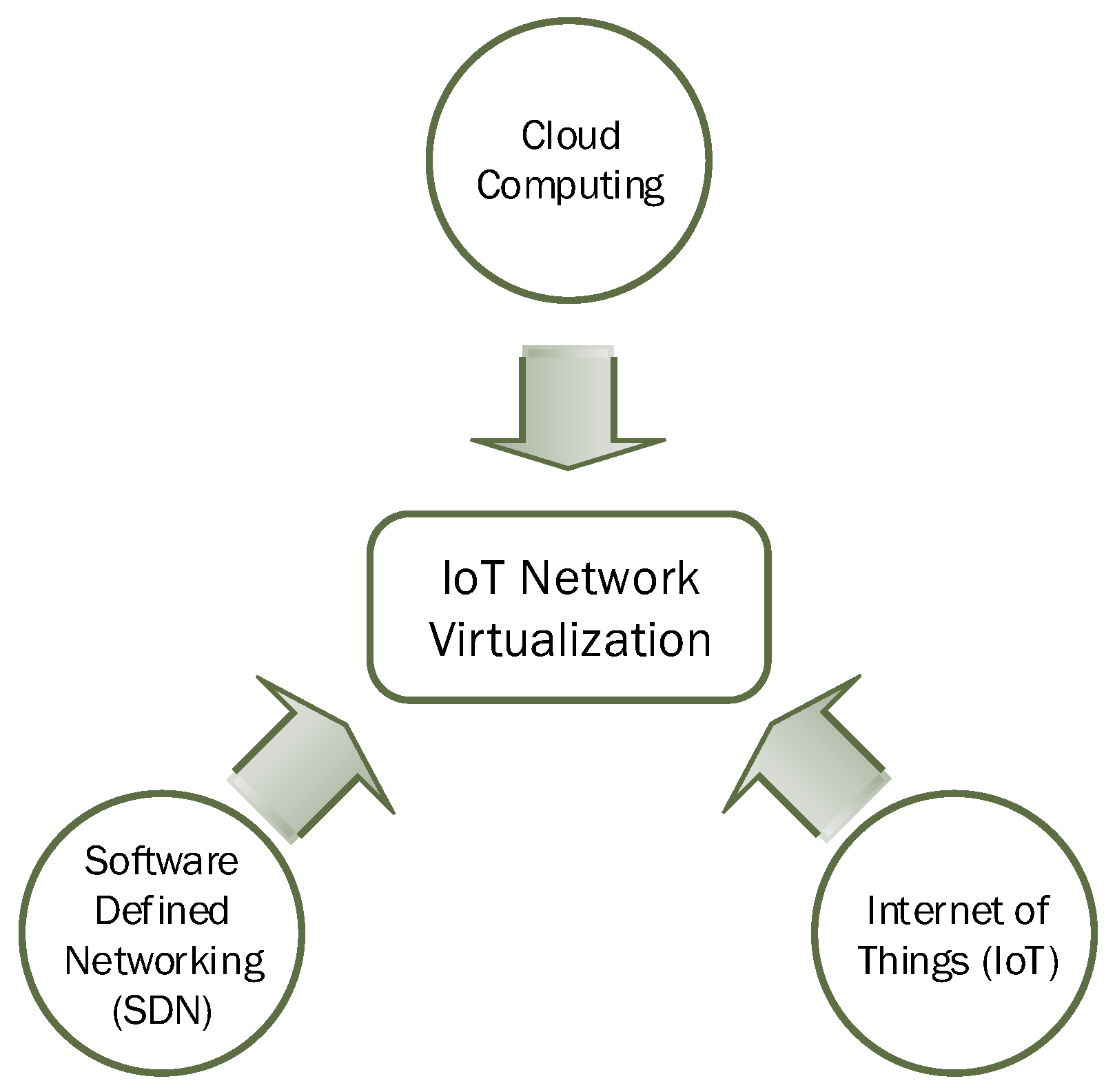
Figure 2 shows the three most relevant and supporting fields that led to the development of virtualized IoT networks.
The rest of this paper is organized as follows: a brief description of related work is covered in
Section 2. The concept of IoT network virtualization is presented in
Section 3 with three use-case scenarios.
Section 4 presents the implementation design for IoT network virtualization through simulation in OMNET++ with a detailed description. Simulation results and discussion are given in
Section 5. Finally, we conclude this paper with an outlook to our future work in
Section 6.
2. Related Work
Since inception, IoT has attracted too much research attention, and it is considered among the future disruptive technologies having the potential to transform every aspect of human life. Various IoT based applications are developed for building a smart environment in various service sectors of smart cities e.g., smart homes, smart health, smart education, security, entertainment, and industry, etc. In the past, WSN was assumed to be operated inside a particular domain, and researchers were against the use of protocol stack (due to resource-constrained devices), and a globally unique ID for each device was not essential. Advancement in information and communication technologies (ICT) and microelectronics has enabled billions of IoT devices connected to the Internet with a globally unique ID. Later, this concept of the virtual sensor network (VSN) was used to refer to a subset of sensor nodes dedicated to a specific task [
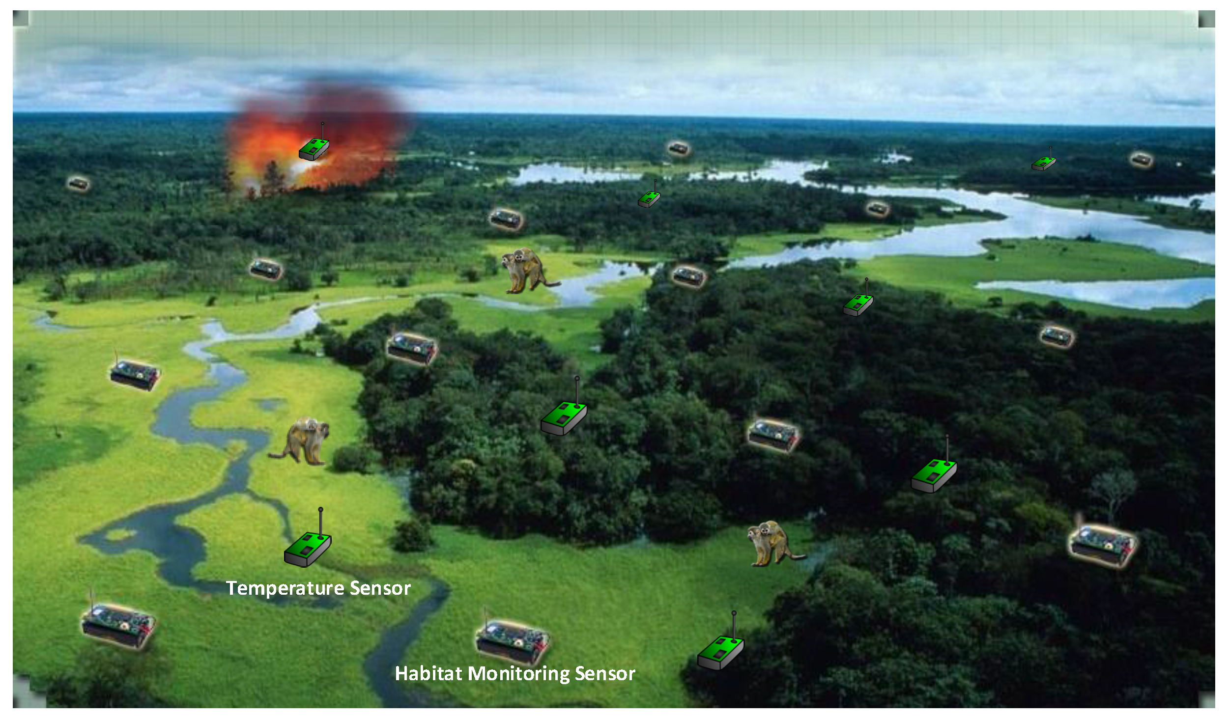
12]. VSN provides logical connectivity between the selected sensor nodes, though these selected nodes may not be physically connected as shown in
Figure 3. In this example scenario, there exist two virtual sensor networks (a) for temperature monitoring (b) for habitat monitoring. The sensor nodes in both networks provide logical connectivity among the sensor nodes of each network.
Various approaches are adapted to exploit the potential and capacity of existing physical networks. Among the initial efforts in this direction include the concept of the overlay sensor network (OSN). An overlay network is established on top of another physical network that provides the infrastructure for communication. Usually, in overlaying the networks, the underlying network is based on entirely different technologies from the one that is overlaid on top of it. Packets from one network are encapsulated inside the packets of supporting networks to enable services that are not provided by an existing network. Commonly used distributed systems such as client–server applications, peer-to-peer networks, and cloud computing are good examples of overlay networks as individual nodes in these types of networks are running on top of the worldwide Internet. The Internet itself is an overlay network originally built on top of existing telephone lines [
13]. Overlay networks are also framed on top of wireless sensor networks in which a virtual topology is created on top of the physical topology in the WSN. Such overlay networks are formed by a subset of nodes in the WSN, and these nodes are not needed to be in the neighborhood of one another or have a one-hop communication link. A virtual link is assumed among the nodes of overlay network which may correspond to a complete path spanning over multiple nodes in the underlying physical network. For a seamless integration of diverse networks, the implementation for overlay network formation is done in the application layer through packets’ encapsulation. However, some overlay networks may require slight modification in underlying layers of the protocol stack. [
14] presents a novel access architecture for QoS provisioning in wireless sensor networks by constructing an overlay network on top of 802.11 WLAN. The overlay network acts as a control plane to ensure fairness among active communication flows with maximum bandwidth utilization.
IoT devices are supposed to be small battery powered devices having limited storage, computation and communication capabilities. To overcome resource constraint issues in sensor nodes and IoT devices, various new models are developed. Cloud-based architecture is commonly used to address this issue. Madria et al. present a concept of sensor cloud to interconnect geographically diversified networks [
4]. They have used virtual sensors to address resource constraint issues in physical sensors. A test-bed has been developed in [
15] a based sensor cloud to support multi-model and multi-user sensor networks based applications. A cloud-based architecture Cloud4sens is proposed [
16] to provide a remote interface for sensors monitoring and controlling. The Things Network provides a set of tools that are more focused on rapid IoT application development with minimal/zero coding efforts through drag and drop operations [
17]. Efficient resource allocation in the virtual sensor network environment is a challenging problem, and various solutions are proposed in the literature to address this issue [
18,
19,
20,
21]. The concept of virtualization in WSN is not new [
22,
23,
24]. Bhattacharya et al. present the idea of community sensor grids for virtualization and sharing of sensing resources across the domains [
6]. Several studies present the prototype implementation of sensor virtualizations, e.g., Raveendranathan et al. have developed a model for sensor virtualization in body sensor networks [
25]. They have also implemented the proposed model using the SPINE2 architecture, which is an open source framework to support domain-specific signal processing and sensing operation of wireless sensor networks. Levis et al. have developed a tiny virtual machine Mate for sensor networks [
26]. Mate provides interfaces to encode complex programs in a very small size (less than 100 bytes), thus avoiding transmission and storage issues in sensor networks. Leontiadis et al. have developed a platform SenShare to decouple sensor networks infrastructure from applications running on top of it [
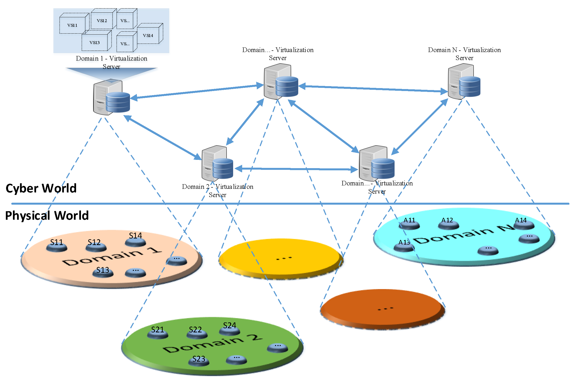
27]. Thus, multiple applications can share the same underlying infrastructure to perform different operations. Furthermore, virtualization in sensor networks can help in the separation of concerns in conventional WSNs. Previously, WSNs were managed and owned by a single entity and the same entity was responsible for sharing their network for service provisioning to various client applications. In the future, a logical network can be established among the virtualization servers for different domains to support resource sharing for provisioning coordinated services to client applications for the future smart world as shown in
Figure 4. For every domain, we may have a virtualization server that holds information about the associated IoT devices in the form of virtual sensors or virtual objects. These virtualization servers can be connected to share resources information across the domains.
Most of the existing studies are focused on the virtualization of IoT devices in the cloud environment so that it easily be replicated and shared among the different applications [
28,
29]. A study presented in [
30] can be considered among the earliest attempts of IoT devices virtualization, although the authors did not use this term explicitly. However, cloud computing technologies provide centralized, reliable access to a high volume of data along with tremendous computation power, but it is not suitable for delay sensitive applications due to significant communication delay in sending data to the centralized cloud server for processing. To address this challenge, edge computing technologies are gaining attention where computations are pushed closer to the origin of data to avoid unnecessary communication delays [
31,
32]. More recently, numerous studies can be found in the literature regarding virtualization of IoT devices, and interested readers can find comprehensive surveys on virtualization of wireless sensor networks in [
33,
34]. SDN based virtualization solutions for IoT devices [
35,
36,
37] are focused on remote management of IoT devices to make necessary configuration changes, but this approach requires computation and storage resources that may result in performance degradation. Cloud-based service virtualization provides a centralized and shared repository of virtual objects for registered IoT devices so that they can easily be shared and replicated. However, all the data collection and processing operations on connected virtual objects were handled in applications logic, and there was no as such need of virtual network formation. With the advent of IoT, two types of devices are connected i.e., sensors and actuators [
38]. In IoT based applications, there exist somehow a linkage or network among sensing and actuating devices that can be realized in the form of virtual IoT formation in the cloud environment among related virtual IoT devices. To the best of our knowledge, there is no study published in the literature related to virtual IoT network formation among virtualized IoT devices and hence the subject matter of this paper.
3. IoT Network Virtualization (INV)
The idea of IoT network virtualization is borrowed from the concept of NFV in the context of SDN and cloud computing. NFV enables the rapid development of the functionalities of real devices in the form of a software package and its convenient deployment in the cloud environment. Moreover, through NFV, these virtual devices can easily be updated, upgraded, replicated and shared.
IoT allows the connectivity of small sensing and communicating devices to the Internet and are attached to daily life objects for remote monitoring and control. Billions of IoT devices are expected to be connected to the Internet in the near future, which will be generating an enormous amount of data. Many research studies suggest and prefer the connectivity of IoT devices to a cloud environment for convenient storage and processing of collected data using advanced data analytics and big data processing schemes supported by the cloud platform. Leading cloud service providers such as Google, Amazon, Microsoft, etc. also provide support and APIs for connectivity of IoT devices directly to their platforms so that its data can easily be consumed and processed by respective client applications. Like virtual machines and virtualized network functions, we can have a virtual representation of IoT devices in the cloud environment commonly referred to as virtual objects. The major difference between NFV and virtual objects is that NFVs have no physical device backing them, whereas virtual objects are backed by real IoT devices. Once IoT devices are connected, and corresponding virtual objects are created in the cloud environment, then a virtual IoT network can be established among associated virtual objects.
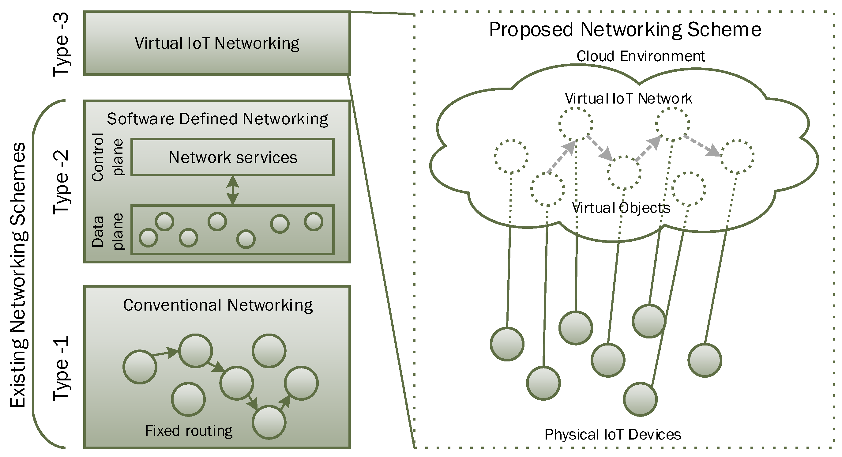
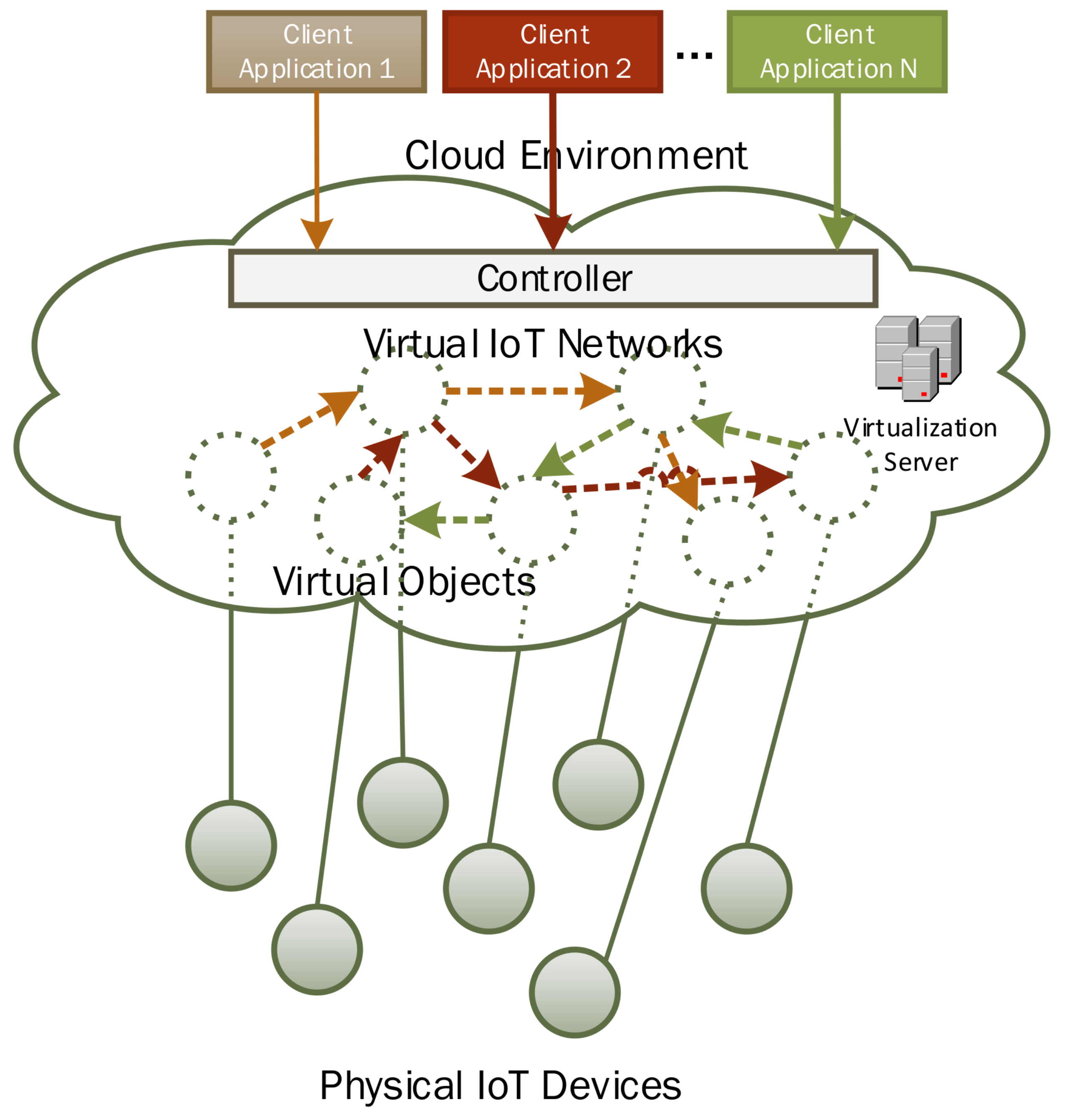
Figure 5 shows the conceptual view of virtual IoT network formation among virtual IoT devices (virtual objects).
Figure 5 also presents a brief summary of the evolution in network types. A type-1 network corresponds to the conventional physical networks where routing information is maintained at intermediate routers. For any changes in the network setting, each router needs to be accessed individually. When the network size grows, individual maintenance of networking devices becomes a tedious job. To overcome these issues, networks of Type-2 were introduced, i.e., SDN. In SDN, data and control plans are separated. The network administrator can use centralized controllers for network configuration and maintenance. The Controller interacts with individual networking devices to reflect necessary changes in their internal routing tables. Networking devices do just the data forwarding as per the rules defined by the controller in their routing tables. The concept of virtualized IoT networks can be considered as the Type-3 networks where the network among connected IoT devices is maintained in the cloud environment through corresponding virtual objects.
Figure 6 shows a more detailed view of virtualized IoT network formation for diverse applications in the cloud environment. In this proposed architecture, client applications only have to communicate with the centralized controller to specify their required network configuration. Just like a controller in SDN networks, the controller module is centralized, responsible for network formation and maintenance.
Figure 6 shows three virtualized IoT networks setup on-demand for different client applications. The proposed architecture supports sharing of the same virtual objects across different networks.
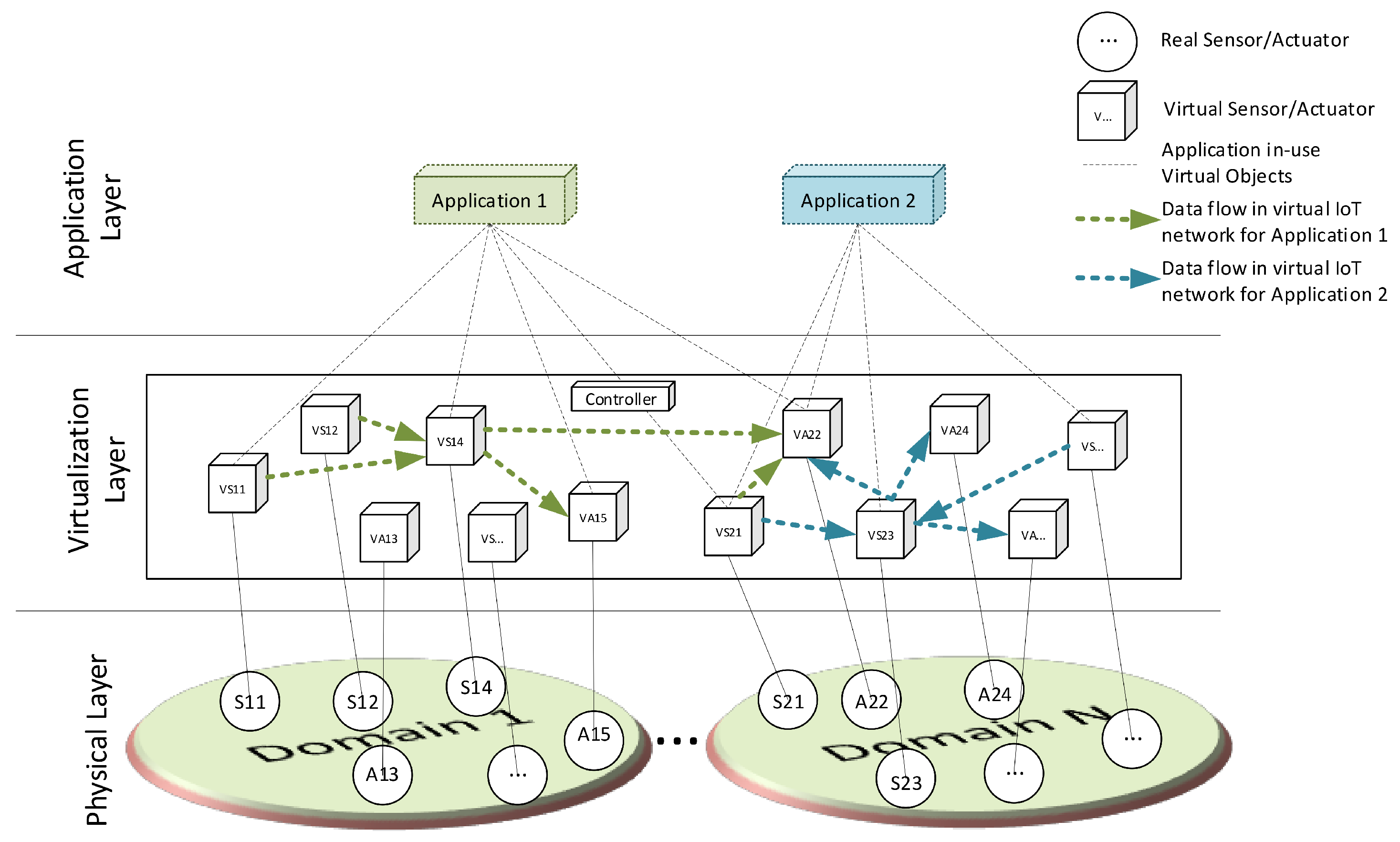
Layering architecture of the proposed system for IoT network virtualization is given in
Figure 7. It has three layers: (a) the Physical layer consists of actual IoT devices that can be sensing and actuating devices connected to the system. The IoT devices can be distributed across different domains sharing the same goals and objectives; (b) the virtualization layer acts as a middleware between client applications and physical IoT devices. Virtual objects are created in this layer for every connected IoT device, and these virtual objects are used by and shared among different client applications. The virtualized IoT network is established among related IoT devices as per client application demand and desired settings. Virtual objects provide an interface to the actual IoT device to consume its services across different applications. (c) Various applications are hosted in the application layer for consuming the services of the underlying virtualization layer. Applications from any domain can have access to the shared resources through the virtualization layer.
Figure 7 also shows the virtualized IoT network formation in the virtualization layer for two different clients in application layers. Applications express the required number of IoT devices with desired connectivity settings through a dedicated interface and the logic is reflected in the form of a virtual network among related virtual objects.
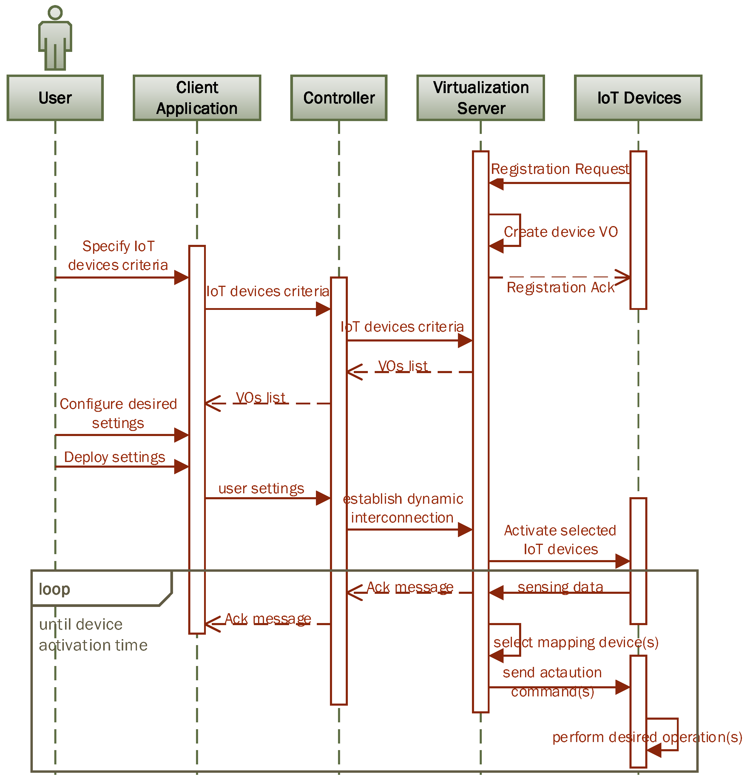
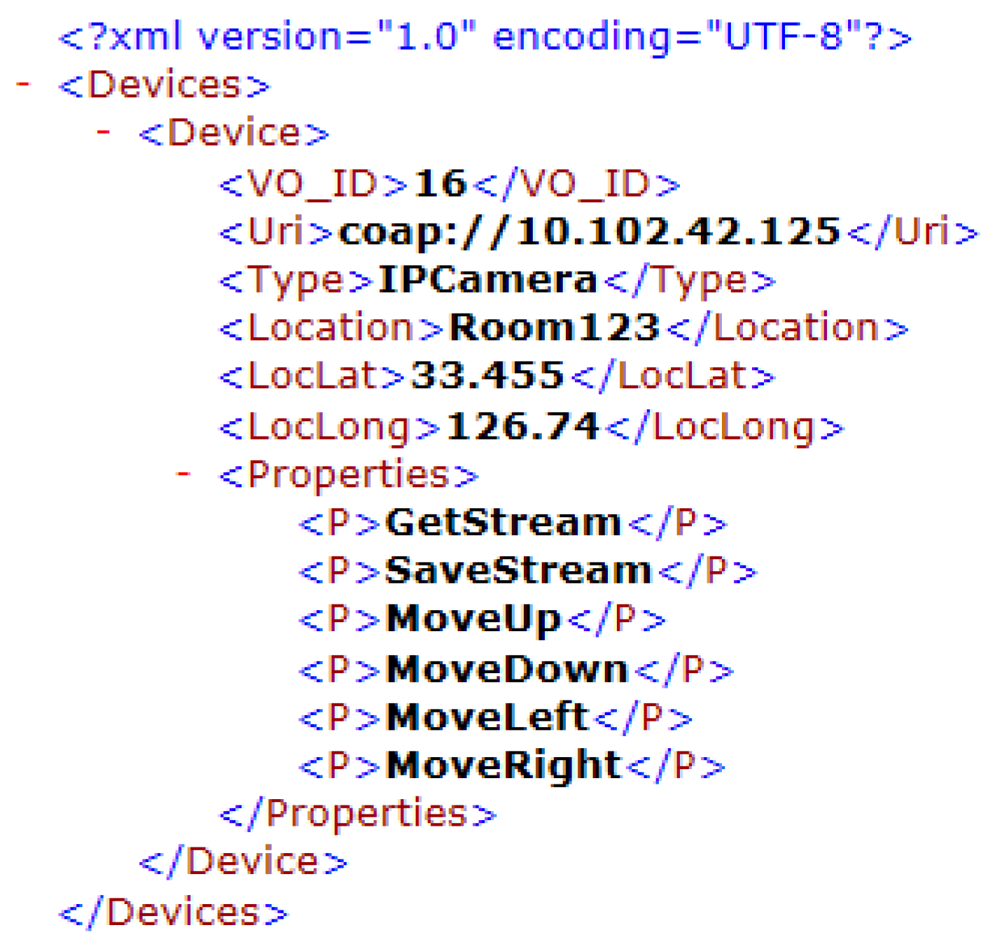
The essential components of the proposed system for IoT network virtualization and its functioning is shown in
Figure 8 via a sequence diagram. The process is initiated with IoT device registration where every IoT device posts its profile information to a pre-configured virtualization server by sending a registration request. A typical virtual object profile for an IP camera has information as shown in XML format in
Figure 9. After the necessary validation of device profile information, a virtual object is created for a corresponding IoT device and an acknowledgment message is sent to the respective device. The virtual object is used by a virtualization server for onward communication with a corresponding IoT device. Afterwards, the user initiates a request via client application for the desired type and number of IoT devices. The Controller processes the request and retrieves virtual objects’ profiles of matching IoT devices as per user specified criteria. Upon receiving virtual objects’ lists at client application, the user specifies and configures desired settings. Afterwards, user desired settings are deployed via client application and the request is submitted to the controller. The Controller is responsible for establishing desired network settings by manipulating virtual objects in the virtualization server. Dynamic connections are made among related virtual objects as per user desired settings by updating the mapping list. Afterwards, an activation command is sent to corresponding IoT sensors to initiate data transmission. Sensing data are received by corresponding virtual objects and then the actuation command is forwarded to the next connected virtual object after selecting the mapped device from the mapping list. The actuating device performed the desired operation and acknowledgment message is sent to the client application. The process continues until the device activation time is over. Connectivity information for a particular virtualized IoT network is purged from mapping list when its activation time is over.
3.1. Master Mapping Table and Flow Tables
In the proposed setup, the virtualization server stores the virtual objects of all connected IoT devices. The Controller can be hosted on the same server, or deployed on a separate server if needed. Virtualization server provides virtual representation for registered IoT devices in the form of virtual objects, whereas the controller module interacts with clients to manipulate connectivity among virtual objects as desired by clients.
Table 1 is the master table maintained at the controller module containing all information about the virtual IoT networks established in the cloud for a typical scenario given in
Figure 7. Two applications are using the virtual objects in the virtualization layer and the communication flow for each virtual IoT network is indicated with a different color. As shown in
Figure 7, some virtual objects are shared by the two applications e.g., VS21 and VA22 are being used by both applications. Two entries are done for VS21 in the master mapping
Table 1 (i.e., Entry ID 1010 and 1011) to handle and generate packets for both applications.
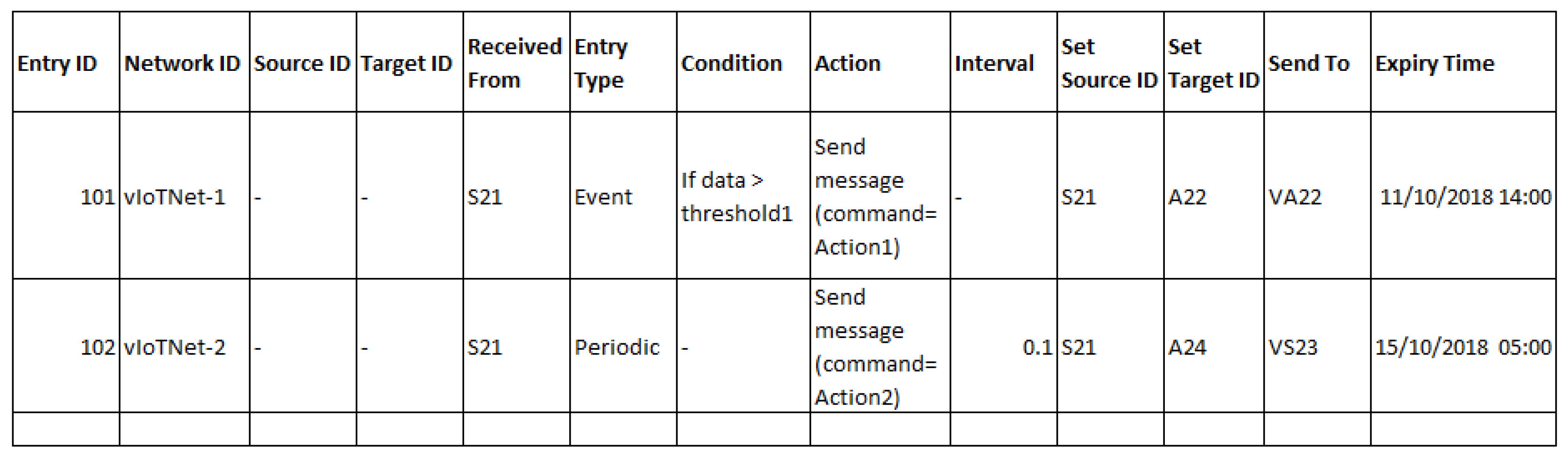
Each entry is uniquely identified with an ID, i.e., entry ID. Every entry in the master table represents the linkage between two real/virtual objects and will belong to a particular virtual IoT network having a unique network ID. This table contains master information about the connectivity among the virtual objects and connectivity information of an individual virtual object is identified with the field ’VO ID’. Every packet generated in this virtual IoT network architecture may be destined for a single/multiple target nodes. Source and Target ID indicate the origin and destination for a particular communication flow. When a virtual object receives a packet from a real device, then it sets the source and target ID as per rules specified by the master mapping table. The field “received from” is used to identify the previous hop of the packet so that it can forward the packet to the next node as identified by the “sent to” field. The entry type field indicates the type of data flow, e.g., event-based, periodic, etc. Expiry time indicates the validity time of a virtual IoT network and all the entries will be purged when its validity time expires.
Sample entries in the flow table for VS21 shown in
Figure 7 are given in
Figure 10. This virtual object is shared by the two applications. A separate entry is made for each application to specify flow rules for data forwarding at the virtual object level. Let us suppose that application 1 builds an event-based system, and its rule will be triggered if the sensor data value is greater then a certain threshold. For a second application, we assume a periodic control system that sends a command to actuator after a regular interval of 0.1 s in this example. When the data packet is received at the virtual object from the real sensor, then its source and target ID fields are set. A single packet received at the virtual object can be forwarded to multiple target nodes by having multiple entries in the flow table. Furthermore, if the flow entry is of an event type, then the condition field is checked if true and then a corresponding action is taken. If flow entry type is periodic, then the interval field is used to set the timer for the next packet transmission.
3.2. Use Case Scenarios
In the following sub-sections, we present three different use case scenarios to illustrate the working and utility of the proposed IoT network virtualization concept. In each scenario, we present a particular application scenario that requires some specific type of connectivity among related IoT devices. Through these examples, we will explain how a virtualized IoT network is established among corresponding virtual objects to achieve the desired application objective.
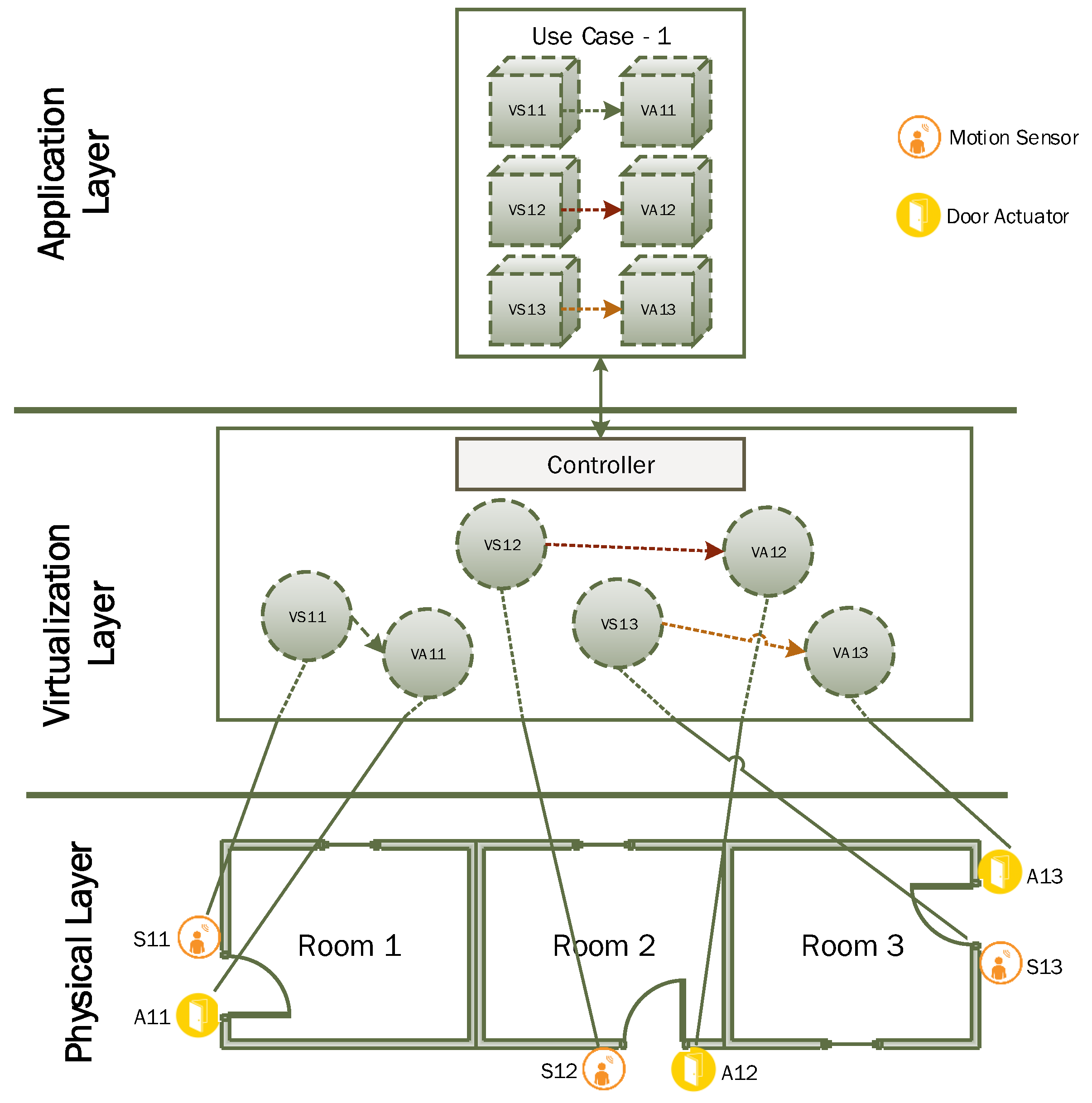
3.2.1. Scenario 1
In this example, we consider a simple scenario where a user wants to develop an IoT based automatic door opening application in a small living area that consists of three rooms. For simplification, we consider two types of IoT devices in this network, i.e., motion sensor and door actuator as given in
Figure 11. We have a motion sensor deployed at the door of every room and door opening and closing is controlled by a corresponding actuator. A total of six virtual objects need to be created at the virtualization layer. This scenario requires a direct one-to-one connection between IoT devices through virtual objects based on simple rules using condition/action. A user can get a virtual list through a client application interface and specify desired connectivity among corresponding sensor and actuator. Users can also specify simple rules indicating a sensitivity level of motion sensing to activation of a door opening actuator. After deployment, the controller will update settings of each virtual object to establish desired connectivity settings among related virtual objects and activation commands will be sent to motion sensors. The motion sensor will start sending motion sensing data at a designated interval to a corresponding virtual object where simple rules will be applied to determine whether or not to send activation commands to door opening actuators.
3.2.2. Scenario 2
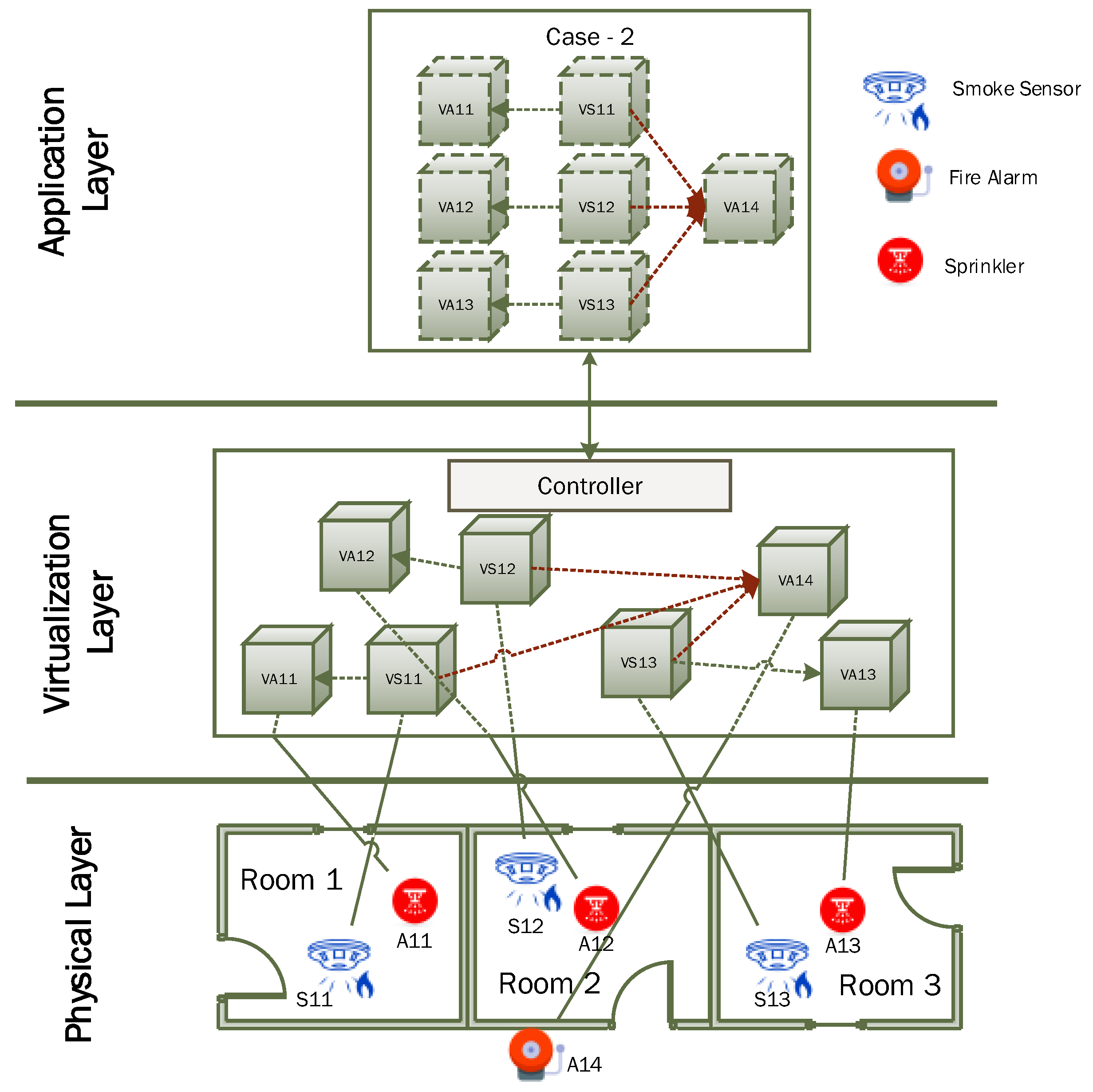
In this case, we consider an example scenario where the client wants to develop an IoT based fire safety application in a small living area that consists of three rooms. For simplification, we consider three types of IoT devices in this network i.e., smoke sensor for fire detection and two actuators i.e., alarm and sprinkler. We have a smoke sensor and sprinkler deployed inside every room and alarm is installed in the corridor as shown in
Figure 12. For this scenario, a total of seven virtual objects are needed to be created at the virtualization layer. The user can get a virtual objects list through a client application interface and specify desired connectivity among corresponding sensors and actuators. Users can also specify simple rules indicating the sensitivity level of smoke sensing for activation of a corresponding sprinkler and alarm. After deployment, the controller will update settings of each virtual object to establish desired connectivity settings among related virtual objects as shown in
Figure 12 and activation commands will be sent to smoke sensors. The smoke sensor will start sending smoke sensing data at the designated interval to a corresponding smoke sensor virtual object where simple rules will be applied to determine whether or not to send activation command to sprinkler and alarm actuator. This scenario requires complex interconnection between IoT devices through virtual objects by establishing one-to-one and many-to-one interconnections. One-to-one connectivity is established between the smoke sensor and corresponding sprinkler, whereas all smoke sensors are also connected to a single alarm actuator which requires a many-to-one type of connectivity. Application logic for this scenario is expressed in the application layer where its implementation is realized in the virtualization layer through the establishment of a virtualized IoT network among related virtual objects.
3.2.3. Scenario 3
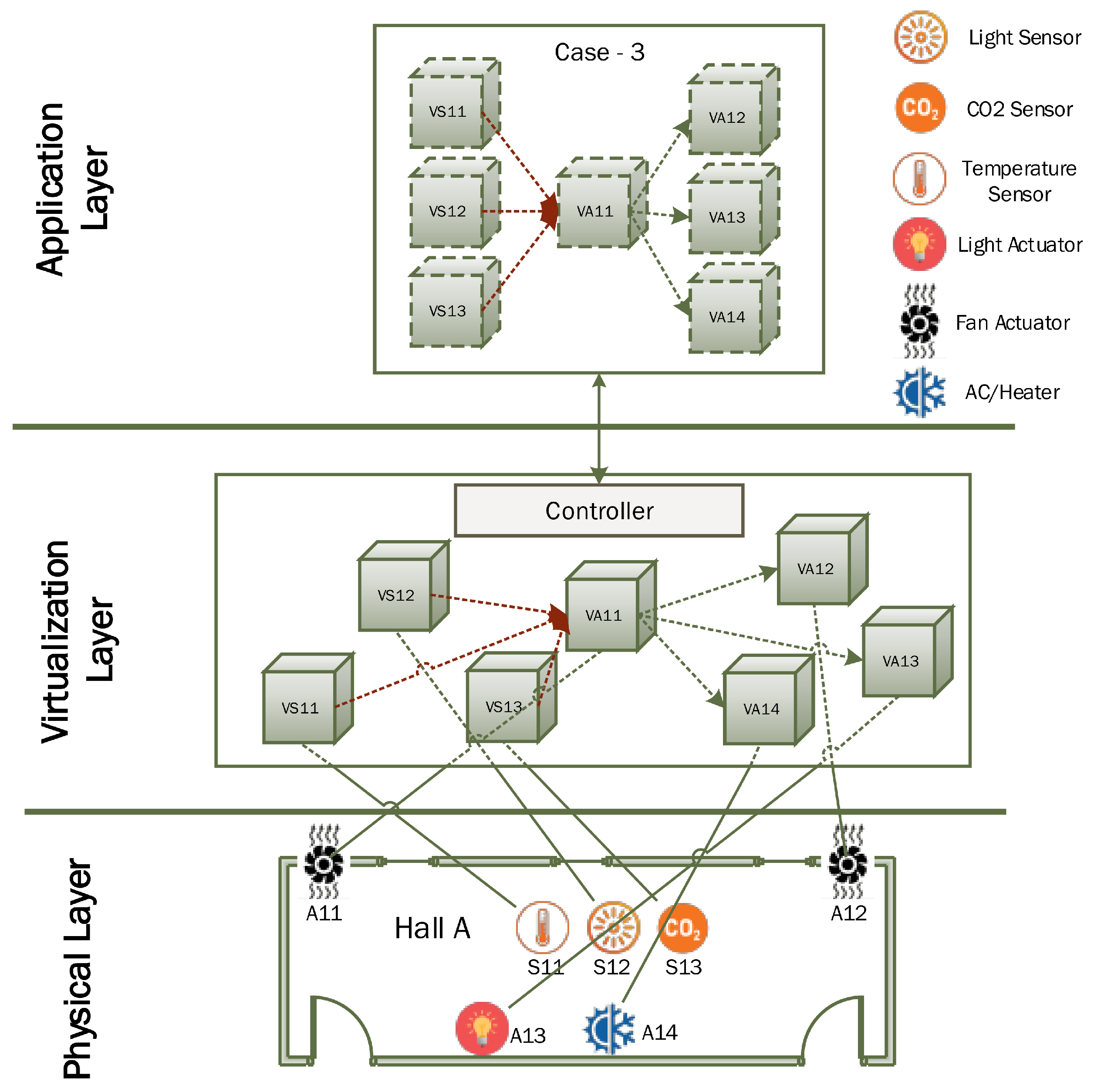
This scenario requires complex interconnection between IoT devices through virtual objects by performing various data fusion, integration and aggregation operations. This scenario is different from the other two cases as here certain virtual objects have the capacity to both receive and send the data. An example application scenario is given in
Figure 13 to better explain this scenario. In this case, the client wants to develop an IoT based indoor environment application in a small living area that consists of a big hall. The user wants to control indoor temperature, lighting and air quality using this smart application. For simplification, we consider six different types of IoT devices in this network, i.e., three sensors—temperature sensor, illumination sensor and CO
sensors, and three actuators i.e., AC/heater, lights, and two fans. The user needs to specify the desired range for indoor temperature, illumination, and air quality. AC will be operated if the indoor temperature is above the desired range to cool down the indoor environment and the heater will be operated if the indoor temperature is below the desired range to heat the indoor environment. Similarly, if the indoor illumination level is below the user desired range, then electric bulbs will be turned on. Likewise, if indoor air quality is getting worse (more CO
concentration than specified level), then the fan will be operated to maintain air quality.
For this scenario, a total of seven virtual objects are needed to be created at the virtualization layer as shown in
Figure 13. The user can get a virtual objects list through client application interface and specify connectivity among corresponding sensors and actuators to achieve the desired objective. The user can also specify simple rules as per the desired range for each indoor parameter for activation of corresponding actuating devices. After deployment, the controller will update settings of each virtual object to establish desired connectivity settings among related virtual objects as shown in
Figure 13 and activation commands will be sent to sensors. Sensors will start sending sensing data about the indoor environment at the designated interval to the corresponding sensor virtual object. As per virtual IoT configuration, all sensing virtual objects will forward the data to a designated fan virtual sensor where simple rules will be applied to determine whether or not to send activation command to each actuator. This scenario requires the establishment of many-to-one and one-to-many connectivity between sensors and actuator virtual objects. Application logic for this scenario is expressed in the application layer where its implementation is realized in the virtualization layer through the establishment of a virtualized IoT network among related virtual objects.
4. Implementation Design
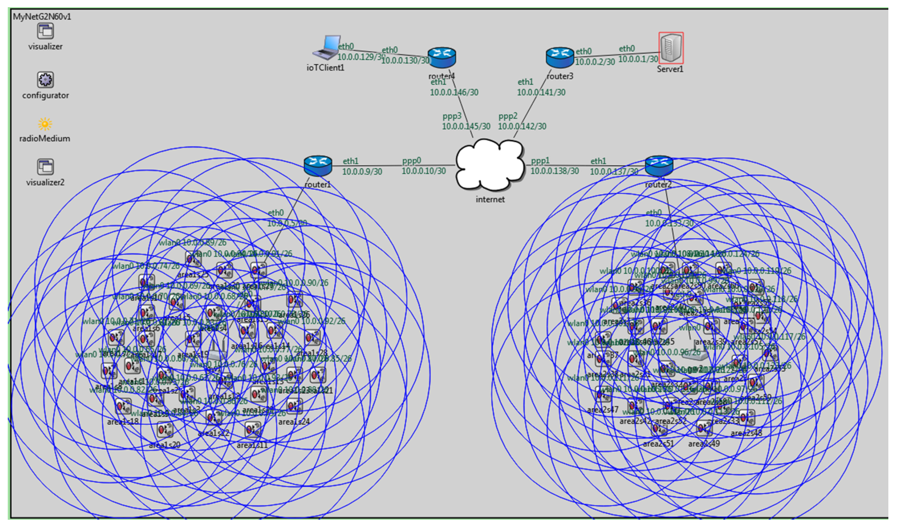
We have configured a hybrid network simulation setup in OMNeT++ for virtual objects network simulation as shown in
Figure 14. OMNeT++ stands for Objective Modular Network Testbed in C++ and it is a very popular simulator for discrete event simulation [
39]. We can also perform network simulation in OMNeT++ by using an INET framework (open-source). This package includes different protocols for communication networks (wired, wireless and mobile networks) [
40]. In this paper, we have used OMNeT++ 5.2 with the INET framework version 3.6.
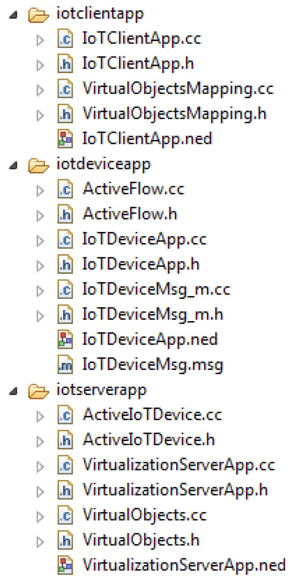
We have developed three application layer protocols in OMNeT++ for Client, Server and IoT devices in our network. The directory structure of these protocols in the OMNeT++ environment is shown in
Figure 14. The server system has virtualization application protocol
VirtualizationServerApp, IoT device has
IoTDeviceApp protocol at the application layer. Afterwards, we have developed an application layer protocol for the client
IoTClientApp to send a request to a virtual objects server for configuration of the desired topology among registered virtual objects to perform the desired operation.
4.1. IoT Message Structure
Before presenting the detailed internal structure of these protocols, we first discuss the message structure that is used in these experiments.
Table 2 presents a brief description of various message fields. Each message has a unique ID for its identification in the simulation environment. In these experiments, various types of messages are generated, e.g., registration request message, acknowledgment message, command message, etc. A message type is an integer number indicating the type of message and
Table 3 presents a brief description of the various types of messages used in these experiments. The data field in the message structure is the most important part of the message structure. Depending upon the message type, associated message content and information are encoded in this field. The parser is used to retrieve information from the data at the receiver side. Data field size is variable as a different type of messages requires different information. The total size of the message is mainly dependent upon the size of this data field. Next, we present a brief description of the three application layer protocols used in this study.
4.2. IoTDeviceApp Protocol
IoTDeviceApp is an application layer protocol designed for both sensing and actuating IoT devices. The directory structure of this protocol given in
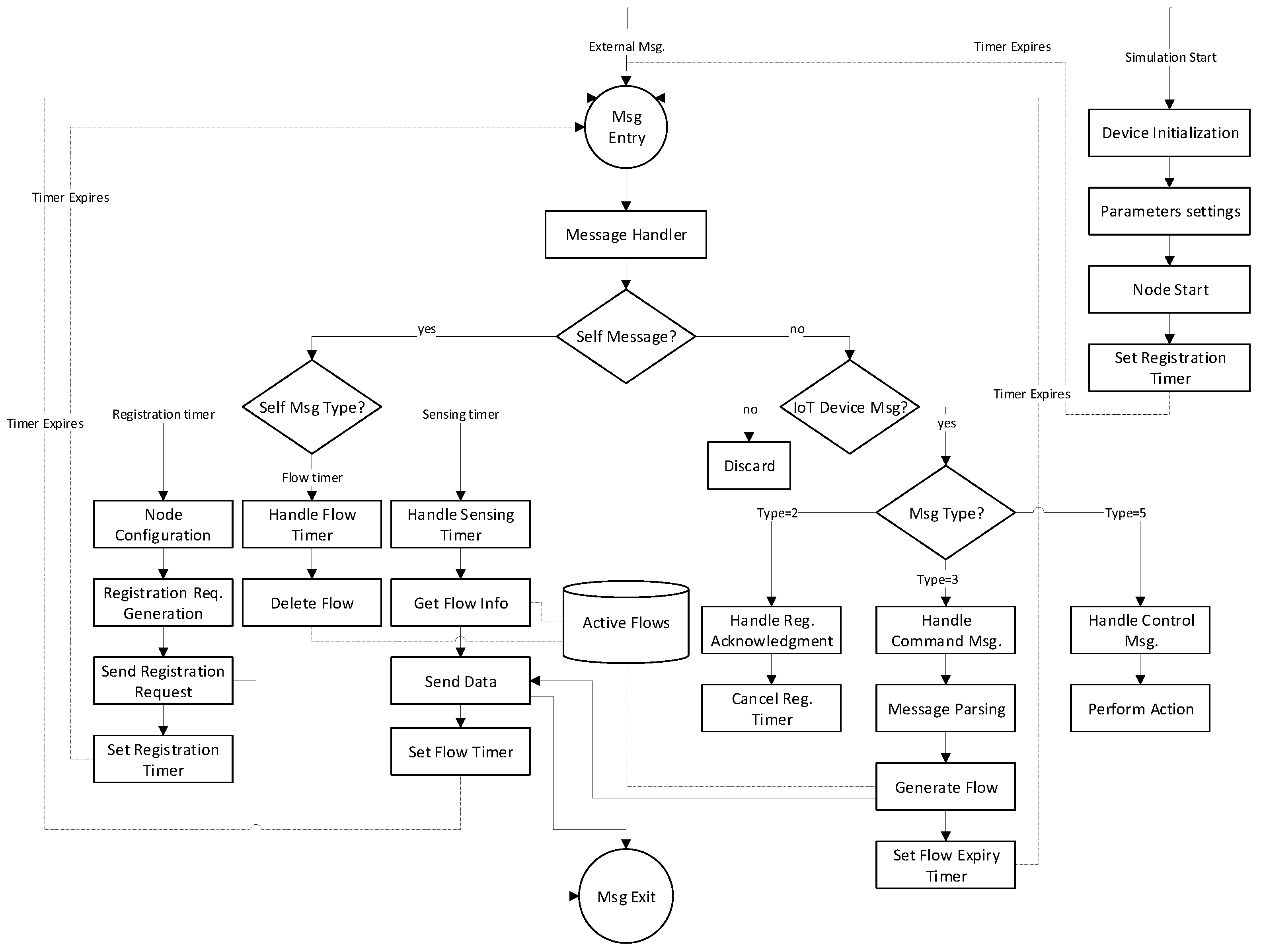
Figure 14 shows the source files used in its implementation. IoTDeviceMsg.msg is the message structure file that is automatically compiled by OMNet++ message compiler. This message structure is shared across all other protocols. This protocol maintains the necessary information in network description (NED) language as required by the OMNeT++ simulator. All application logic of this protocol is implemented in C++ language. This protocol also keeps track of active flows by holding information about the target device, packet sending interval and flow expiry time. The working flow diagram of this protocol is given in
Figure 15.
At simulation startup, IoT nodes perform necessary configuration settings and then sets a timer for sending registration request. When the registration timer gets expired, OMNeT++ sends a timer message to the corresponding module as a self message. IoT device generates registration request message (Type = 1) by encoding its profile information in its data field and then sends this message to the underlying transport layer protocol for onward transmission to the virtualization server. The timer is set again to re-transmit the registration request if no acknowledgment is received within a certain amount of time. Upon reception of an external message, first, we check if it is a self message (timers) or an external message and then it is processed accordingly. When a registration acknowledgment message (Type = 2) is received, then device updates its internal settings as registered and cancels the previously set timer to avoid the re-transmission of registration request.
Afterwards, the IoT device may receive an external command message (Type = 3) from the virtualization server to initiate data transmission at a specified sending rate. The message is parsed and active flow is generated and its expiry timer (flow timer) is set. Then, the first data packets (Type = 4) are sent and the sensing timer is set to continuously send packets. If the IoT device is an actuating device, then it may receive a control message (Type = 5) from a virtualization server to perform a designated operation.
4.3. VirtualizationServerApp Protocol
VirtualizationServerApp is an application layer protocol designed for IoT virtualization server node. The directory structure of this protocol given in
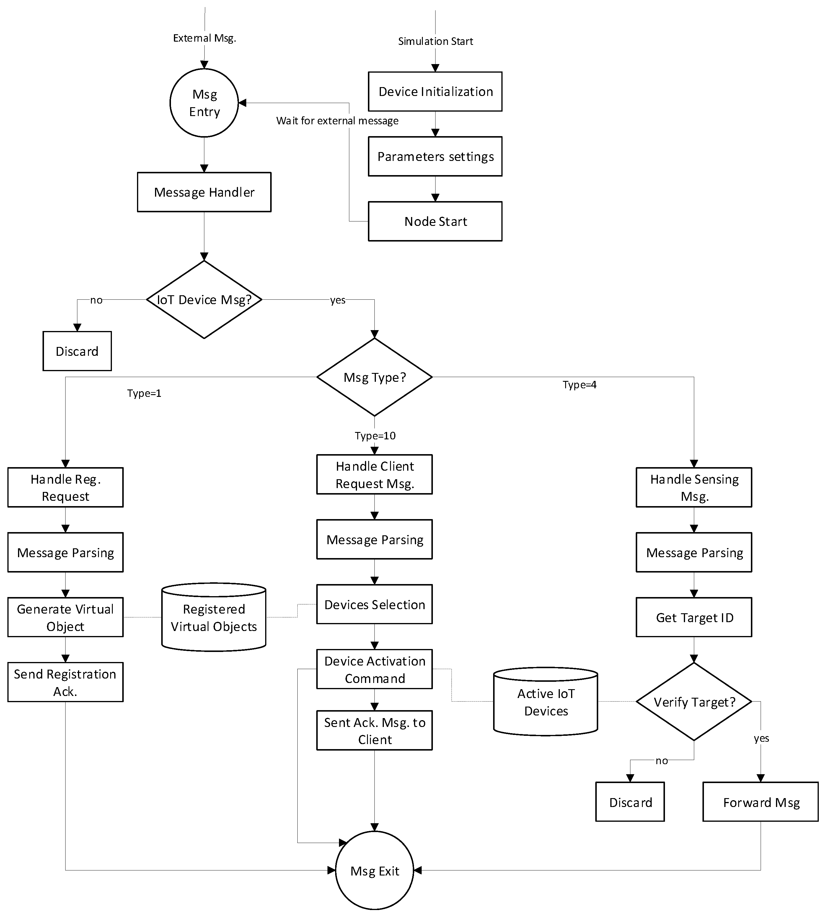
Figure 14 shows the source files used in its implementation. Application logic of this protocol is implemented in C++ language, whereas information about the active IoT devices is stored in a data structure. Active IoT devices are those devices that are currently used in some virtualized IoT network and have active communication flows. Profile information of a registered IoT device is also maintained. The working flow diagram of this protocol is given in
Figure 16. At simulation startup, the virtualization server performs necessary configuration settings and then waits for an external message either from IoT devices or clients. Three types of messages are expected at the virtualization server (a) Registration request message (Type = 1), which results in the creation of virtual objects for corresponding IoT devices after necessary validation followed by sending an acknowledgment message; (b) a request message from client application (Type = 10) for the establishment of a virtualized IoT network through selection of desired virtual objects. The activation command is sent to the selected IoT device to initiate data transmission. Acknowledgment is sent to a client application; (c) sensing message (Type = 4) from activated IoT devices for onward forwarding to the corresponding target IoT device after verification.
4.4. IoTClientApp Protocol
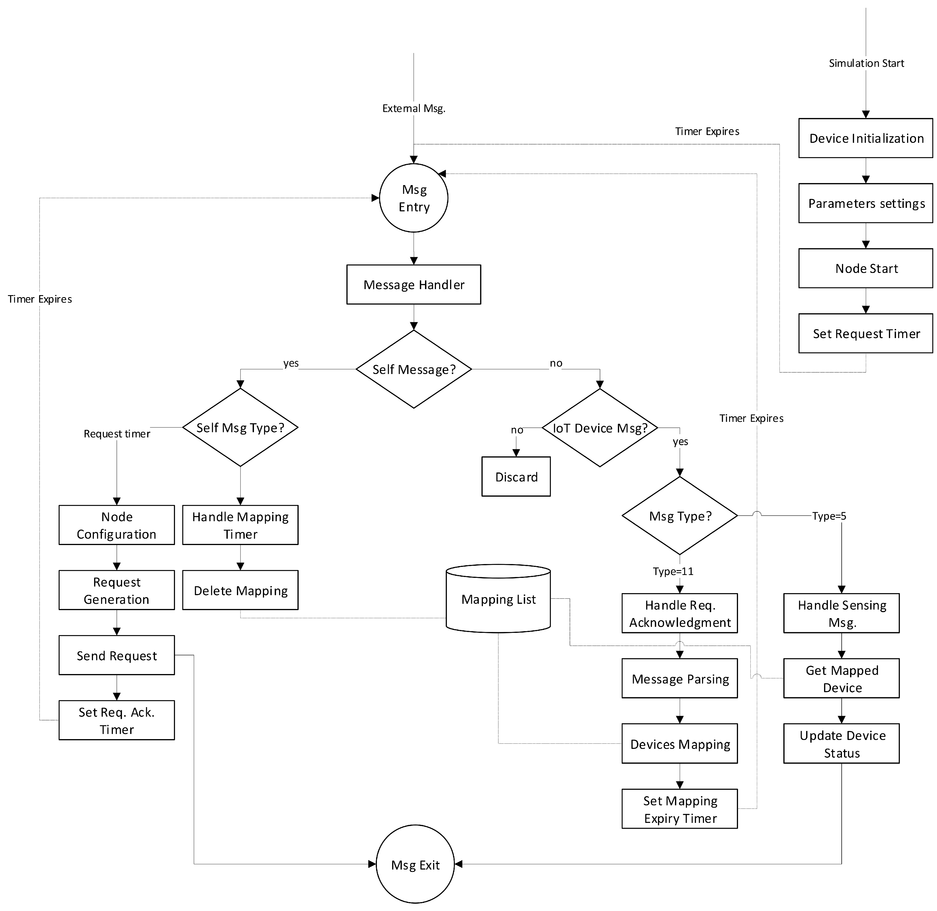
IoTClientApp is an application layer protocol designed for IoT client devices. This protocol allows the user to get the desired virtual objects list from the virtualization server and specifies required network topology settings by mapping corresponding virtual objects.
The working flow diagram of this protocol is given in
Figure 17. Before the simulation start-up, we specify the request sending time for the client device in a simulation initialization script file i.e., omentpp.ini. At simulation startup, the client device performs necessary configuration settings and then sets a timer for sending virtualized IoT network formation request (Type = 10). When the request timer gets expired, OMNeT++ sends a timer message to the corresponding module as a self message. The client device generates a request message (Type = 10) by encoding its desired virtualized network topology information in its data field and then sends this message to the underlying transport layer protocol for onward transmission to the virtualization server. The request timer is set for its re-transmission if no acknowledgment is received from the server within the specified time. After the reception of the acknowledgment message, the client device stores requested mapping information in its database. A mapping timer is also set to purge the corresponding mapping entries from its data store when it is no longer needed. A copy of the sensing and control message is also sent to the client device by the virtualization server to keep its status updated.
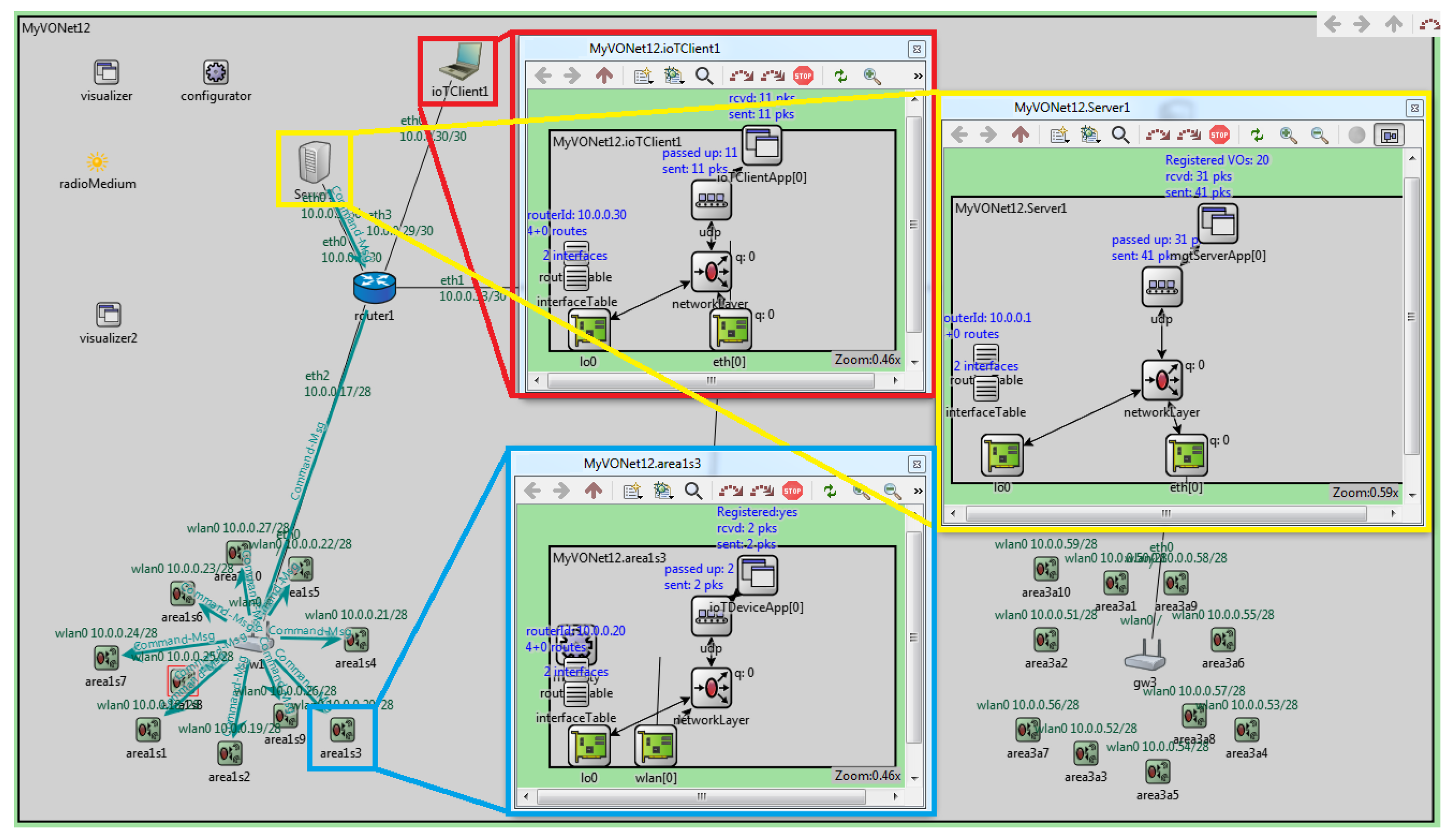
For the sake of illustration, a graphical view of nodes internal layered architecture is highlighted in
Figure 18 (red rectangle for virtualization server, blue rectangle for client device, and yellow rectangle for IoT node). At the virtualization server, an instance of the
VirtualizationServerApp protocol is used at the application layer. Likewise, instances of
IoTClientApp and
IoTDeviceApp protocol are used at the application layer of client device and IoT nodes, respectively.
In the beginning, IoT devices are associated with designated gateway nodes. Then, all IoT devices send registration requests to virtualization servers through the gateway node. IoT node color indicates its registration status i.e.,
Registration request contains corresponding IoT device profile information. Upon registration, the virtualization server creates a virtual object (VO) for each IoT device to hold its profile information which is also used for onwards communication and control with/of corresponding IoT devices. Screen-shot given in
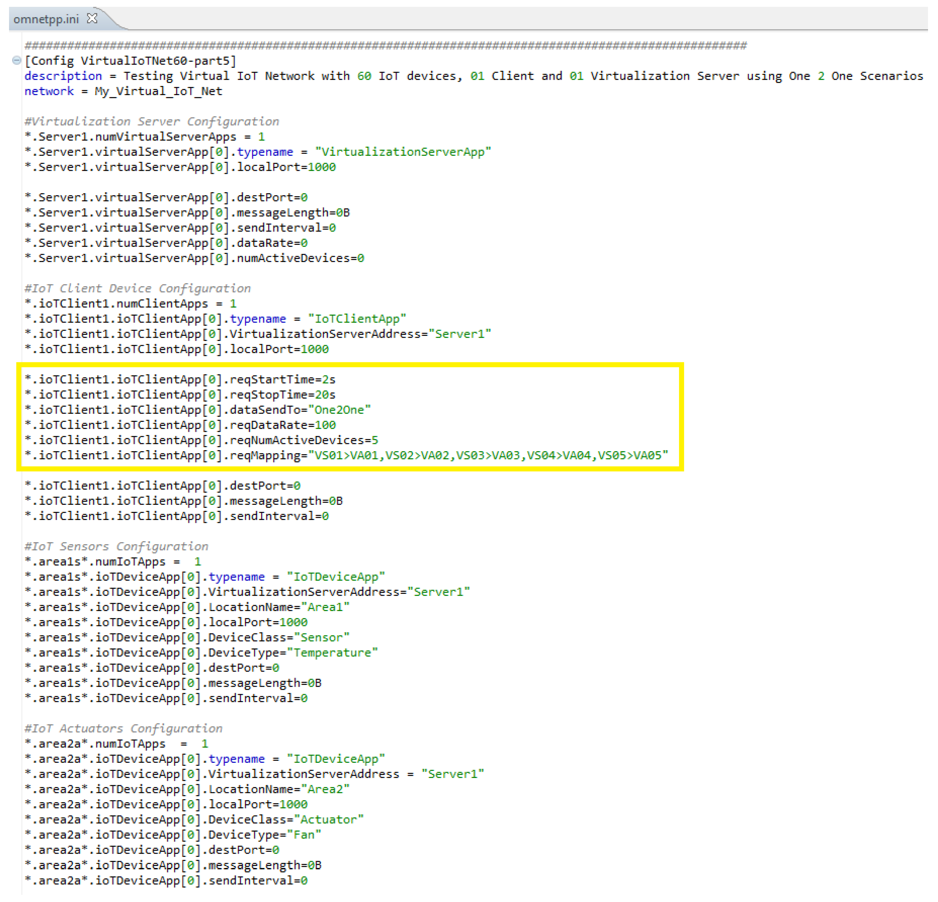
Figure 18 is taken when the registration process of all IoT devices was completed and the activation command message is sent by a virtualization server to an IoT device. Furthermore, the tag on the application layer also indicates that 20 IoT devices are registered at the virtualization server (Registered VOs = 20). Similarly, the tag on the application layer of the IoT device is changed to Registered = yes indicating its registration with the server is successfully completed. After registration, virtualization servers can receive requests from client devices and send various commands to registered IoT devices using its VO e.g., to get its operational status, to initiate data transmission, etc. Data transmission is initiated through a request sent by Client to
VirtualizationServerApp using indicated part in an omnetpp.ini file as given in
Figure 19.


