Article

Feasibility Study of Passive Bistatic Radar Based on Phased Array Radar Signals

1
National Key Laboratory of Science and Technology on ATR, National University of Defense Technology, Changsha 410073, China
2
School of Electronics and Communication Engineering, Sun Yat-sen University, Guangzhou 510275, China
*
Author to whom correspondence should be addressed.
Electronics 2019, 8(7), 728; https://doi.org/10.3390/electronics8070728
Submission received: 5 June 2019 / Revised: 19 June 2019 / Accepted: 20 June 2019 / Published: 26 June 2019

Abstract

:
This paper presents the concept of a passive bistatic radar (PBR) system using existing phased array radar (PAR) as the source of illumination. Different from PBR based on common civil illuminators of opportunity, we develop an experimental PBR system using an high-power air surveillance PAR with abundant signal modulation forms as the transmitter. After the introduction of the PBR system and PAR signals, it can be concluded that the agility of the waveform parameters of PAR signal brings two problems to the signal processing of the PBR systems, which are not discussed in conventional PBR systems. The first problem is the time and frequency synchronization of the system, so we propose a direct wave parameter estimation method based on template matching to estimate the parameters of the transmitted signal in real time to achieve time and frequency synchronization of the system. The second problem is the coherent integration for moving target detection and weak target detection, so we propose a coherent integration method based on Radon–Nonuniform Fast Fourier Transform (Radon-NUFFT) to deal with the problems introduced by the agile waveform parameters. Preliminary results from the field experiment demonstrate the feasibility of the PBR system based on PAR signals, and the effectiveness of the proposed methods is verified.

1. Introduction

A passive bistatic radar (PBR) system performs target detection and localization by exploiting noncooperative illuminators of opportunity. PBR offers many advantages over conventional monostatic radar systems, including lower cost, harder to detect, higher immunity to electronic countermeasures, no requirement for frequency allocation, and the ability to counter stealth targets due to the bistatic configuration of PBR systems. Therefore, many kinds of civil illuminators have been exploited by PBR systems, such as FM radio [1], Integrated Services Digital Broadcasting-Terrestrial (ISDB-T) [2], Digital Video Broadcasting-Terrestrial (DVB-T) [3,4,5], Long-Term Evolution (LTE) [6], Wireless Fidelity (Wi-Fi) [7], and Global Navigation Satellite System (GNSS) [8]. However, those communications signals are not designed for use in radar, which may cause ambiguities due to the signal structure [9], and the maximum detectable range may be small due to the limited transmitting power.
Compared with civil illuminators, a dedicated radar transmitter usually transmits signals with a more ideal ambiguity function and higher transmitting power. German passive radar system Klein Heidelberg [10] was the first PBR system based on existing hostile radar, and in recent years, some PBR systems which utilize existing radar as their transmitter have been proven to perform target detection successfully [11,12,13]. Furthermore, phased array radar (PAR) has the advantages of stronger transmitting power and higher reliability. However, the complexity of PAR signals poses unique challenges to the signal processing of a PBR system, so PBR systems based on PAR signals still remains a broad area of research.
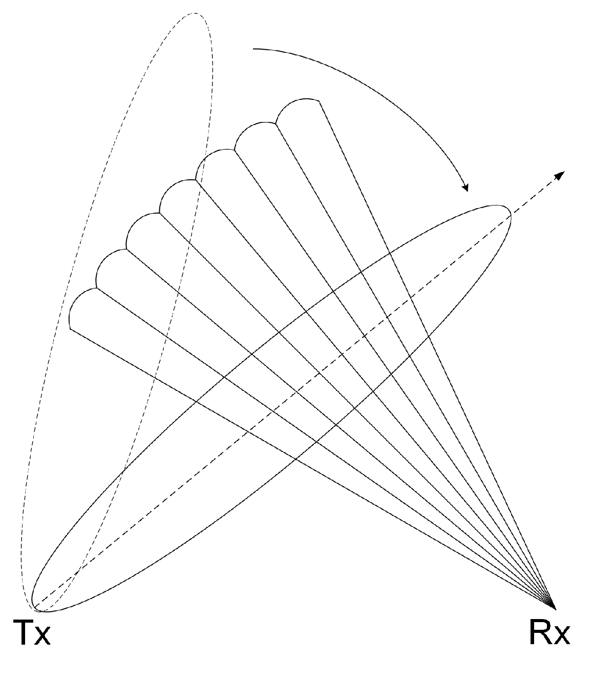
The exploited illuminator of our PBR system is a high-power air surveillance PAR, which is defined as cooperative but non-dedicated. It is cooperative in the sense that the information about signal waveform is available but is considered non-dedicated as its operations is solely for its own monostatic radar purposes and that no changes are applied to enhance PBR capabilities. The PAR adopts agile radar parameters to improve the anti-jamming ability. Liner frequency modulated (LFM) waveform is used as a transmitting signal. The PAR transmits a group of signals with the same carrier frequency (CF) and bandwidth (BW) for seconds; the CF and BW change randomly among different groups, while the pulse width (PW) and pulse repetition interval (PRI) are different among different pulses in each pulse group. The agility of the waveform parameters of transmitting signal brings two problems to the signal processing of our PBR system. The first problem is the time and frequency synchronization of the system, and the second problem is the coherent integration for moving target detection and weak target detection.
For the first problem, we use a reference channel to receive the direct wave signal and to estimate the parameters of the transmitted signal in real time to achieve time and frequency synchronization of the system. The parameters we need to estimate include BW, PW, CF, and time of arrival (TOA). To solve the problem of LFM signal detection and parameter estimation, many literatures have proposed many algorithms for different applications, such as Wigner–Hough transform [14], Lv’s distribution [15], and Ensemble Empirical Mode Decomposition-Fractional Fourier Transform (EEMD-FRFT) [16]. Qian proposed a method based on generalized Radon Fourier transform for the parameter estimation of direct wave signal [17], but it requires a lot of searching and calculation, which cannot be realized in real time. Since the PAR transmits a deterministic signal and the parameter template library of the signal waveform has been established in advance, we propose a direct wave parameter estimation method based on template matching to realize the time and frequency synchronization of the PBR system.
For the second problem, since the duration of a group of pulses with the same CF and BW is generally longer than a second and the coherent processing interval (CPI) for coherent integration will not exceed one second, we perform coherent integration for signals with the same CF and BW, while the PRI is random and PW is staggered. In recent years, many methods have been proposed for coherent integration, such as Keystone transform [18], Radon Fourier transform (RFT) [19], axis rotation moving target detection [20], and scaled inverse Fourier transform [21], which are only applicable for conventional radar. As for radar signals with random PRI and staggered PW, it can be concluded that the random PRI will introduce the problems of irregular range cell migration (RCM) and nonuniform phase fluctuations among different pulses and that the staggered PW will introduce the problem of the irregular range-Doppler coupling effect. The problem of nonuniform phase fluctuations among different pulses can be converted to the problem of spectral analysis of nonuniformly sampled complex-valued data. As for spectral analysis of nonuniformly sampled data, a method based on interpolation [22,23] cannot be applied when the Doppler frequency of the moving target is higher than the pulse repetition frequency of the radar. Li proposed a method based on nonuniform Fast Fourier Transform (NUFFT) for random PRI PD radar [24], but the compensation of the irregular RCM is not covered in this paper. Tian proposed a method based on Radon nonuniform Fractional Fourier Transform (Radon-NUFrFT) for a random PRI radar [25], but it is only applicable for periodic nonuniformly sampled signals, which cannot solve the non-periodic, nonuniform phase fluctuations and the irregular range-Doppler coupling effect. Pan proposed a method based on the Radon-iterative adaptive approach (Radon-IAA) [26] to solve the problems introduced by the random PRI, but it requires a lot of iterative calculations, which is difficult to apply directly to engineering practice. Hence, we propose a method based on Radon-NUFFT to deal with the problems in the coherent integration for a radar signal with random PRI and staggered PW.
The remainder of this paper is organized as follows. 
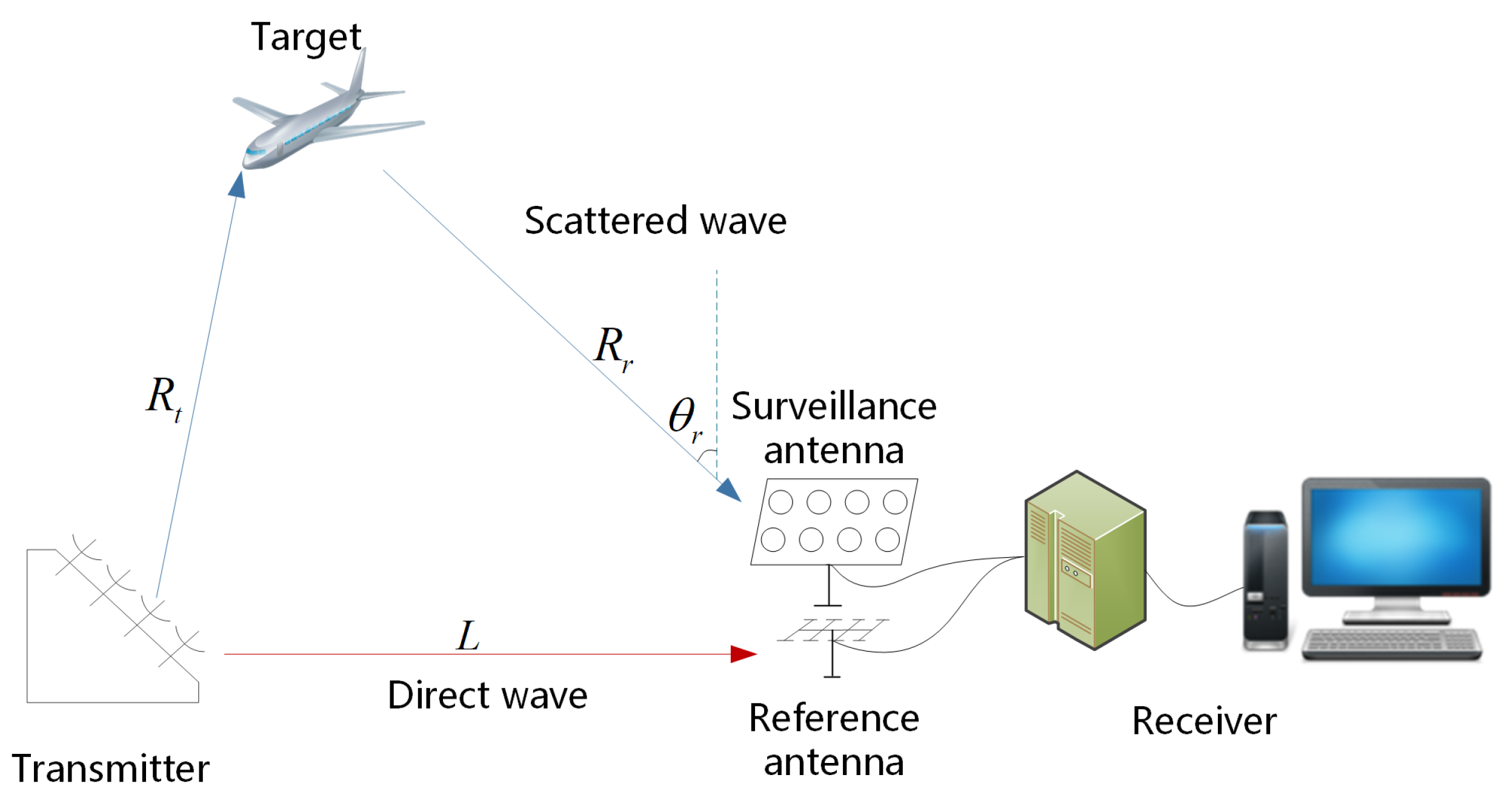
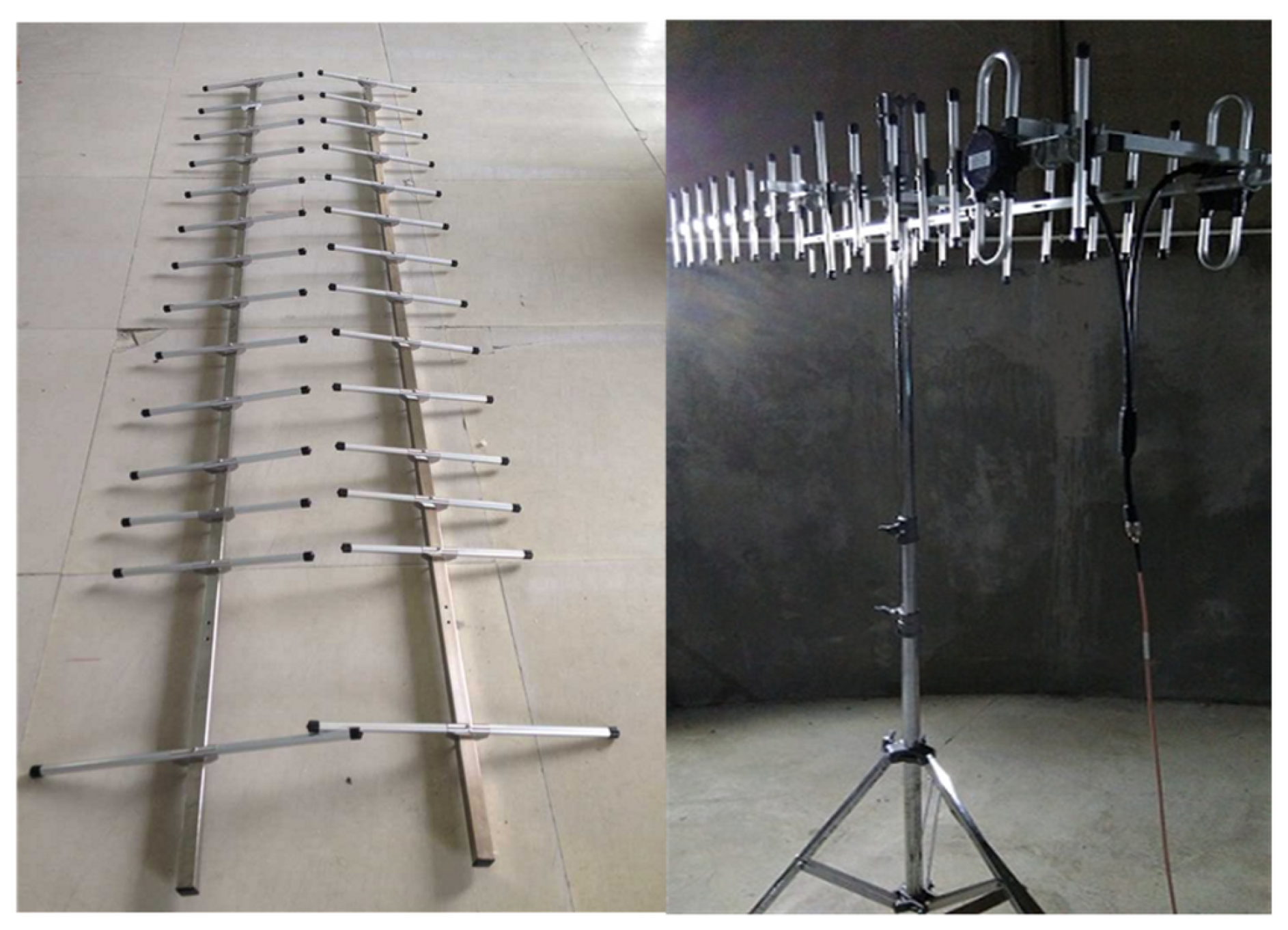
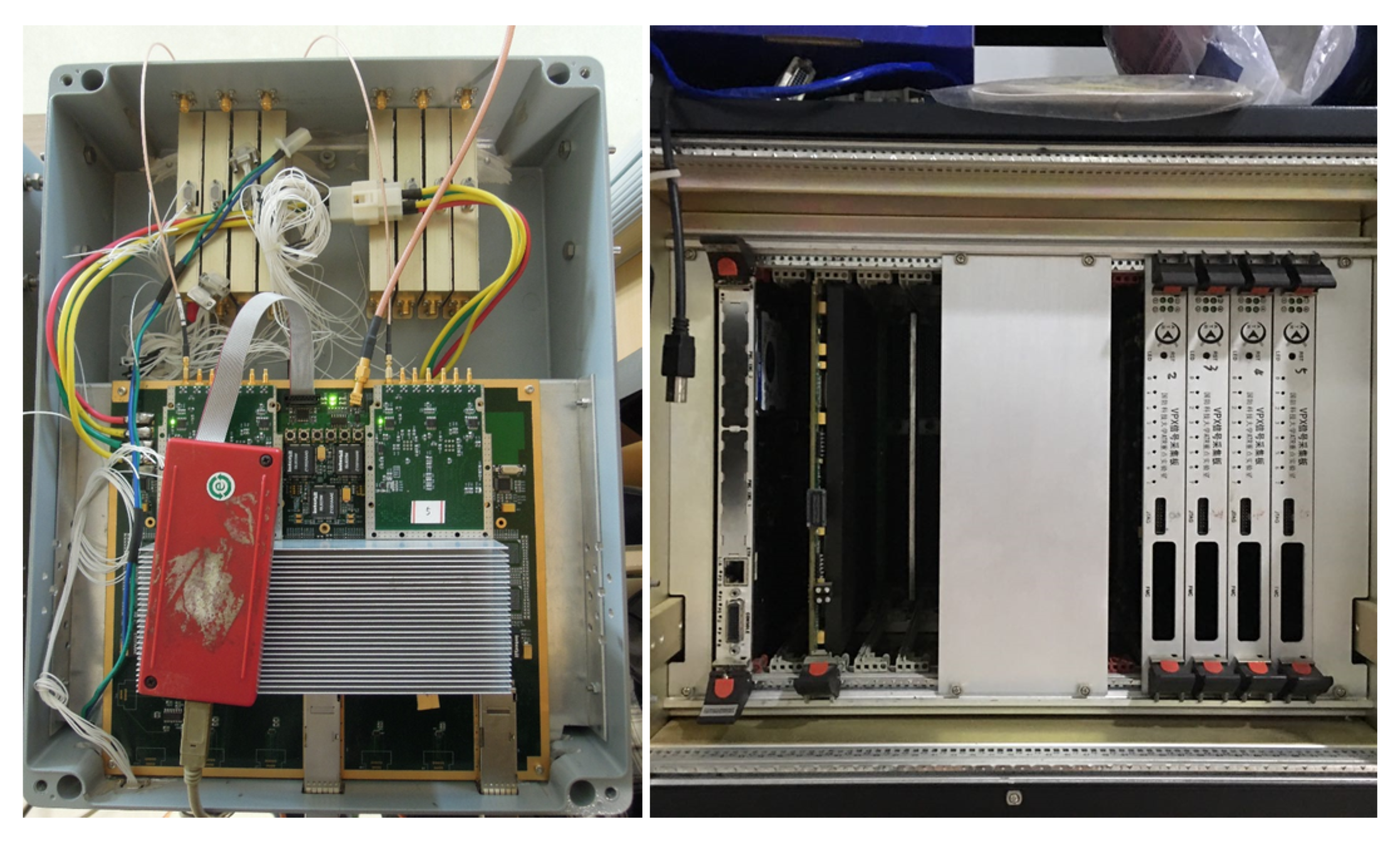
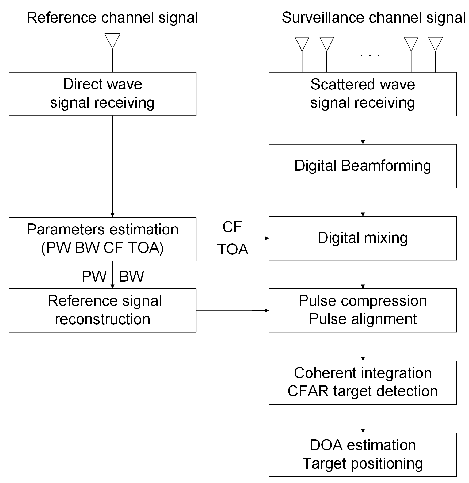
Section 2 introduces the PBR system in general, including the geometry, hardware, and signal processing flow of the PBR system. Section 3 establishes the mathematical model of direct wave signal and describes the parameter estimation method based on template matching. Section 4 establishes the mathematical model of echo signal of a moving target firstly; then, the coherent integration method based on Radon-NUFFT is described, and simulation results are performed. Section 5 presents the experimental results to verify the performance of the PBR system. Section 6 concludes the paper.

2. Overview of Experimental PBR System

2.1. Geometry of the PBR System

The experimental PBR system consists of a reference antenna, a surveillance antenna, and a receiver. As shown in Figure 1, the reference antenna points in the direction of transmitter and receives the direct wave signal and the surveillance antenna covers the surveillance area to receive the scattered signal simultaneously.
As shown in Figure 1, the transmitter and receiver are separated by a distance noted as L. Suppose that there is an aircraft target in the air, the distance between the target and transmitter is R t and the distance between the target and receiver is R r . The azimuth of the target relative to the surveillance antenna is θ r .
When scattered off a target, the combined distance traveled by the signal can be calculated as
R t + R r = L + c Δ t
where c is the velocity of light and Δ t is the time delay between the target echo and the direct wave signal. After the range sum ( R t + R r ) is calculated, according to the triangular geometry, the distance between the target and receiver can be calculated as follows
R r = ( R t + R r ) 2 L 2 2 ( R t + R r + L sin θ r ) = ( L + c Δ t ) 2 L 2 2 ( L + c Δ t + L sin θ r )
Therefore, the target positioning can be realized by the PBR system as long as we get the time delay Δ t and the azimuth of the target relative to the surveillance antenna θ r .

2.2. Hardware of the PBR System

The receiving antenna we designed consists of a reference antenna and a surveillance antenna. Figure 2 shows the photographs of the reference antenna. A Yagi antenna with 30 elements is chosen as the reference antenna due to its good directivity and simplicity, which is used to receive the direct wave signal to estimate the detailed parameters of the transmitted signal. The Yagi antenna has a gain of 13.5 dBi and a half-power beam width (HPBW) of 14 . The surveillance antenna is used to receive the scattered wave signal. Since the scattered wave is extremely weak relative to the direct wave, it requires a high gain and the ability to cover a wide range of airspace. Therefore, we use a phased array antenna, which has a total of 64 array elements with 8 rows and 8 columns in triangle arrangement; each array element has a gain of 9 dBi and is circularly polarized.
In order to sample the signal from reference antenna and surveillance antenna simultaneously, a high performance Analog-to-Digital Converter (ADC) chip EV10AQ190 of E2V company was applied in the sampling module. The highest sampling frequency of the chip is 5 GHz, and the 3 dB bandwidth is 3 GHz. A high performance signal processing platform based on VPX is utilized to deal with large amounts of real-time data. Figure 3 shows the photographs of the high performance sampling module and signal processing platform based on VPX.

2.3. Signal Processing Method

The flow chart of the signal processing method is shown in Figure 4. Respectively, for the reference channel signal and surveillance channel signal, the brief process is described as follows.
Firstly, for the reference channel signal, the CF, BW, PW, and TOA of the direct wave pulse are obtained by the parameter estimation method based on template matching, which is a key step in the signal processing flow, and we will discuss it in detail in Section 3. The TOA is used to distinguish different pulse signals, and then each pulse signal is down-converted to baseband according to the estimated CF. The estimated PW and BW are used to reconstruct the baseband reference signal to perform matched filtering on the basedband scattered wave signal.
As for the surveillance channel signal, the simultaneous multi-beam forming method is adopted to cover the surveillance airspace. In addition, since the CF of transmitted signal hops in a broad frequency range, wideband beamforming algorithm must be adopted. The PBR system forms seven frequency invariant beams to cover the surveillance airspace, as shown in Figure 5.
After digital beamforming, the receiving data are transformed from array element space to beamspace. We use the estimated CF to down-convert the signal to baseband to reduce the amount of data to be processed subsequently. Then, pulse compression is performed and combined with the reconstructed reference signal, which concentrates the energy of target echo and improves the range resolution. Then, the pulses are realigned according to the peak position of the direct wave signal after pulse compression.
After pulse alignment, we divide the pulses into different groups according to the CF of pulses and, then, perform coherent integration according to the CPI we set for the signals in each group, which can be used to filter out fixed clutter and to improve moving target detection performance. The coherent integration method based on Radon-NUFFT will be introduced in Section 4. Then, the constant false alarm rate (CFAR) detection method is used to detect targets.
Finally, after target detection, an amplitude comparison direction measurement is implemented by taking advantage of the beams that may contain echo of targets. Combined with the azimuth and bistatic range of the target, the actual position of the target can be obtained.

3. Direct Wave Signal Parameter Estimation Method Based on Template Matching

Different from conventional PBR based on a civil illuminator that directly use the direct wave as the reference signal for cross correlation with scattered wave, we first estimate the parameters of the direct wave signal to achieve the time and frequency synchronization of PBR system. Therefore, the parameter estimation of the direct wave signal is a very important step in the whole signal processing flow and should be accurately completed in real time. Therefore, combined with the parameter template library of PAR signal, we propose a direct wave parameter estimation method based on template matching.

3.1. Signal Model

The PAR transmits the LFM signal, which can be expressed as
s t t m , t ^ = A Rect t ^ τ m exp j 2 π f m t m + t ^ exp j π μ m t ^ 2
where A is the amplitude of transmitted signal, t m is the slow time, m indicates the pulse number, t ^ is the fast time, Rect ( · ) is the window function, τ m is the pulse width, f m is the carrier frequency, and μ m = B m / τ m is the chirp rate with bandwidth B m . Then, the direct wave signal received by the reference antenna can be represented as
s d t m , t ^ = σ d A Rect t ^ L / c τ m exp j 2 π f m t m + t ^ L / c exp j π μ m ( t ^ L / c ) 2
where σ d is the attenuation coefficient and L is the distance between the PAR transmitter and reference antenna. The parameters to be estimated are f m , τ m , B m , and the time of arrival.
Based on the a priori knowledge of the waveform of PAR, we can build a template library of radar parameters, including CF template library noted as f ( k ) | k = 1 , 2 , , N f , PW template library noted as τ ( k ) | k = 1 , 2 , , N τ , and BW template library noted as B ( k ) | k = 1 , 2 , , N B , where f ( k ) , τ ( k ) , and B ( k ) are the specific templates in the signal parameter template library and N f , N τ , and N B are the number of parameters of CF, PW, and BW respectively. Based on these prior information, we can use a method based on template matching to estimate the parameters of direct wave signals in real time.

3.2. Proposed Method

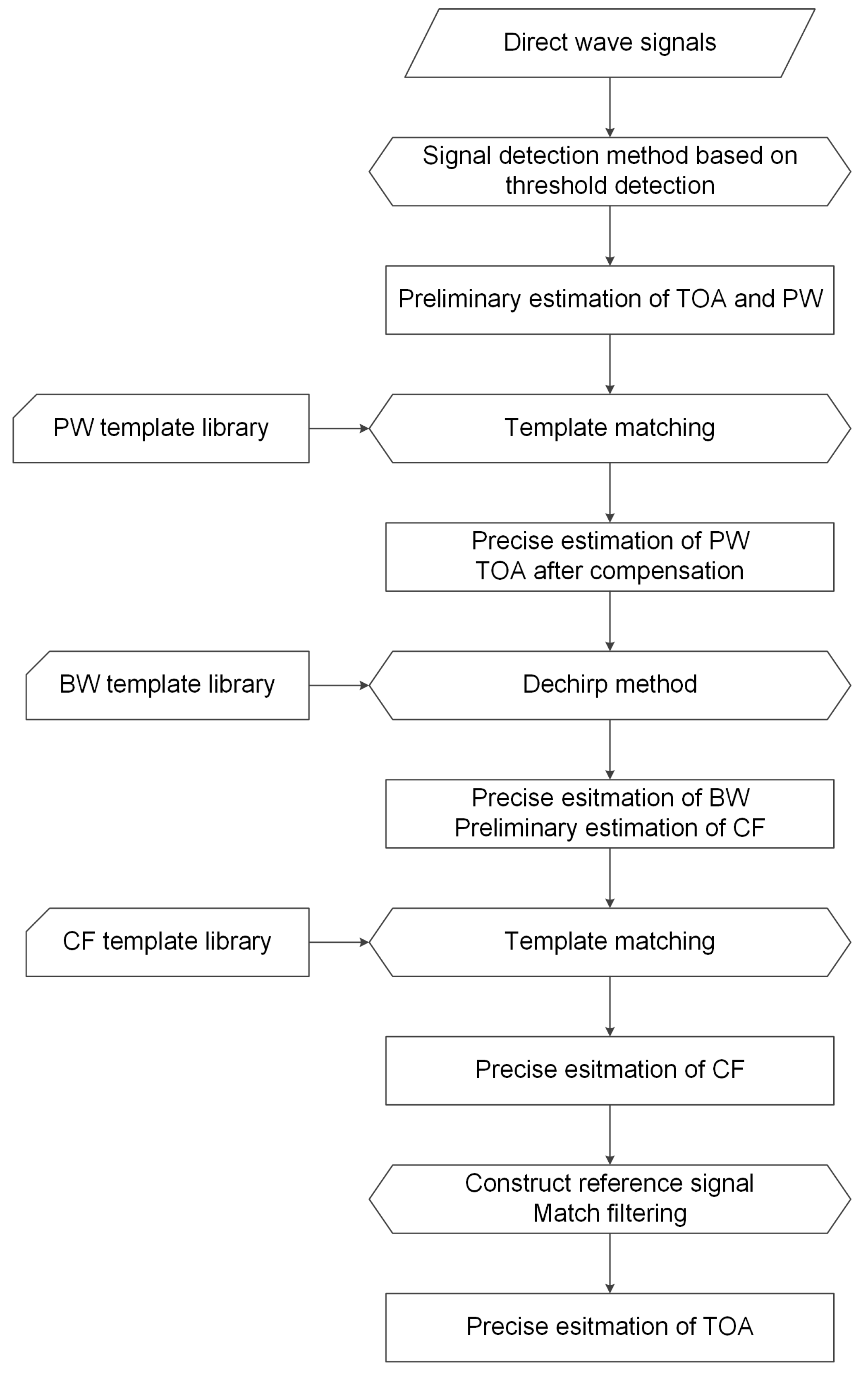
Figure 6 shows the flow chart of the direct wave parameter estimation method. Firstly, the double threshold detection method is used to detect the LFM signal and to roughly estimate the PW and TOA; then, by matching with the PW template, the precise estimation of the PW can be obtained. Secondly, the BW is accurately estimated by the dechirp method, and the CF is roughly estimated, then the precise estimation of CF is obtained by matching with the CF template. Finally, the accurate PW, BW, and CF are used to reconstruct a reference signal so as to accurately estimate the TOA by means of matched filtering. Next, we will introduce the process of direct wave parameter estimation step by step.
Step 1. In order to detect the LFM signal, it is necessary to determine the detection threshold. Since the signal-to-noise ratio (SNR) of a direct wave signal is generally high, after calculating the noise energy σ 2 , set a threshold V T that is slightly larger than σ 2 . Using the double threshold detection method, it is considered that the pulse has arrived only when the signal amplitude continuously exceeds the threshold for p times. Similarly, the pulse is considered to be ended only when the amplitude is continuously below the threshold for q times, wherein the values of p and q are determined by the SNR of the direct wave signal. After that, the preliminary estimated arrival time T ^ s , end time T ^ e , and preliminary estimated PW τ ^ are obtained.
Step 2. Comparing τ ^ with the PW template library τ ( k ) | k = 1 , 2 , , N τ , choose τ 0 which is closest to τ ^ in the PW template library; then, τ 0 is the precise estimation of PW. Thus, the PW estimation error is ε = τ ^ τ 0 , and the arrival time and end time are compensated, which can be expressed as
T ^ s t a r t = T ^ s + ε / 2 , T ^ e n d = T ^ e + ε / 2
Step 3. Combined with the BW template library, the dechirp method is used to accurately estimate the BW and to preliminarily estimate the CF of the direct wave signal. Firstly, intercept the signal s p of interval T ^ s t a r t , T ^ e n d ; s p contains a total of M = τ 0 · F s points, where F s is the sampling rate of the signal. As the BW template library is B ( k ) | k = 1 , 2 , , N B , the possible chirp rate of the signal can be
k 1 = B 1 τ 0 , k 2 = B 2 τ 0 , , k N B = B N B τ 0
Then, construct reference signals with different chirp rates, which can be expressed as
s r e f 1 = e j π k 1 i / F s 2 , i = 1 , 2 , , M s r e f 2 = e j π k 2 i / F s 2 , i = 1 , 2 , , M s r e f N B = e j π k N B i / F s 2 , i = 1 , 2 , , M
Multiply s p with different reference signals s r e f 1 , s r e f 2 , , s r e f N B to obtain the dechirped signal s d c 1 , s d c 2 , , s d c N B , and then, perform a fixed-point FFT on the signal to obtain the spectrum S d c 1 , S d c 2 , , S d c N B . Measuring and comparing the peak value of S d c 1 , S d c 2 , , S d c N B , the chirp rate k max corresponding to the spectrum with the largest peak value is the chirp rate of the signal, and then, the accurate BW can be calculated as B 0 = k m a x · τ 0 . At the same time, the frequency position corresponding to the peak value in the spectrum is the preliminary estimation of CF of the signal, noted as f ^ c . Comparing f ^ c with the CF template library f ( k ) | k = 1 , 2 , , N f , choose f 0 which is closest to f ^ c in the CF template library; then, f 0 is the precise estimation of CF.
Step 4. Combining with the estimated parameters of the signal, including B 0 , τ 0 and f 0 , reconstruct a reference signal noted as
s m f = e j 2 π f 0 i F s + π B 0 τ 0 i F s 2 , i = 1 , 2 , , M
Using the reference signal s m f to perform matched filtering on the whole signal; then, the peak position of the result is the accurate TOA of the direct wave pulse.

4. Coherent Integration Method Based on Radon-NUFFT

Since the radar signal we want to perform coherent integration on has random PRI and staggerd PW, after analyzing the signal model of the echo of moving target, a coherent integration method based on Radon-NUFFT is proposed to solve the problems caused by the random PRI and staggered PW.

4.1. Signal Model

Suppose the bistatic velocity of the target is v 0 , the initial distance between the target and transmitter is R t 0 , and the initial distance between the target and receiver is R r 0 ; then, the bistatic range sum of the target can be expressed as
R t m , t ^ = R t 0 + R r 0 v 0 t m + t ^ = R 0 v 0 t m + t ^
where R 0 = R t 0 + R r 0 and R 0 is the initial range sum.
Then the time delay between the target echo and the transmitted signal is Δ t = R t m , t ^ / c . As the transmitted signal is noted as Equation (3), the echo signal from the target can be represented as
s r t m , t ^ = σ r A Rect t ^ Δ t τ m exp j π B τ m t ^ Δ t 2 exp j 2 π f c t m + t ^ Δ t
where σ r is the scattering coefficient of target and the signals to be analyzed have the same CF noted as f c and BW noted as B.
The baseband signal of the target echo after down-conversion can be given as
s b t m , t ^ = σ r A Rect t ^ Δ t τ m exp j π B τ m t ^ Δ t 2 exp j 2 π f c Δ t
After the reconstruction of reference signal, pulse compression is performed and the result can be represented as
s P C t m , t ^ = σ r A B τ m sinc π B + f d t ^ 2 R 0 v 0 t m c + f d μ m exp j π f d 2 μ m · exp j 4 π f c f d R 0 v 0 t m c exp j π f d t ^ 2 R 0 v 0 t m c + f d μ m
where f d = 2 v 0 f c / c denotes the Doppler frequency and μ m = B / τ m is the chirp rate. Based on the assumption that the radar signal is narrowband signal and v 0 c , the above formula can be simplified as follows:
s P C t m , t ^ = A m sinc π B t ^ 2 R 0 v 0 t m c f d μ m exp j 2 π f d t m
where A m is the complex amplitude of the signal.
It can be observed from Equation (13) that the amplitude of the signal is proportional to B τ m ; since the signal pulse width is agile, the amplitudes of different pulses will be different. Also, the signal envelope varies with 2 R 0 v 0 t m / c f d / μ m , which can be divided into two terms for analysis. The former term 2 R 0 v 0 t m / c is the RCM caused by target motion; the latter term f d / μ m is caused by the range-Doppler coupling effect. Since the slow time is nonuniform, which will cause nonuniform RCM and since μ m is different for different pulses, it is necessary to compensate the RCM and range-Doppler coupling of different pulses accordingly. In addition, the phase of the signal with respect to the slow time is exp j 2 π f d t m , so the nonuniform slow time will lead to the nonuniform phase fluctuations among different pulses and traditional Fourier transform among slow time dimension cannot be applied.

4.2. Radon-NUFFT Method

Since the irregular RCM 2 R 0 v 0 t m / c is correlated with R 0 , v 0 , and t m and the irregular range-Doppler coupling effect f d / μ m = 2 v 0 B / λ τ m is correlated with v 0 and τ m , we can compensate them by searching through the motion parameters R 0 and v 0 for each pulse respectively.
As for the nonuniform phase fluctuations exp j 2 π f d t m among different pulses, which can be converted to the problem of spectral analysis of nonuniformly sampled complex-valued data, we use the nonuniform discrete Fourier transform (NUDFT) of nonuniform sampling data, which is given as follows:
y ( f k ) = i = 0 N 1 x i e j 2 π N f k t i
where x i is the nonuniformly sampled data at nonuniform sampling time t i , N is the total number of sampling points, and f k is the frequency point we want to analyze. However, the NUDFT algorithm requires a large amount of computation, so we use a NUFFT method based on a class of regular Fourier matrices [27], which is much faster than NUDFT. For the nonuniformly sampled data sequence { x ( t i ) } i = 1 N , the spectral estimation at f k can be denoted as y ( f k ) = NUFFT [ x ( t i ) , f k ] .
Figure 7 shows the flowchart of the proposed method. The coherent integration time T n , the number of pulses N p , the range search scope [ r m i n , r m a x ] , and interval Δ r are predetermined according to the dwell time of antenna and radar parameters. The searching scope of the initial velocity and interval are preset based on prior information such as moving status of targets to be detected. Therefore, the number of range searching parameters is N r = ( r m a x r m i n ) / Δ r , where · denotes the round up to an integer operation and the number of velocity searching parameters is N v = 2 v m a x / Δ v . Therefore, the moving trajectories of the target determined by the searching parameters can be given as follows:
r ( t m ) = r i v j t m
where m = 1 , 2 , , N p , r i = r m i n + ( i 1 ) Δ r , i = 1 , 2 , , N r , v j = v m a x + ( j 1 ) Δ v , and j = 1 , 2 , , N v . Then, compensate the irregular range-Doppler coupling 2 v j τ m / B λ for each pulse.
For the signal shown in Equation (13), extract the N p dimension data vector for coherent integration.
X N p = s P C t m , 2 ( r i v j t m ) c 2 v j τ m B λ
At last, calculate the spectral estimate of X N p at frequency f j = 2 v j / λ to compensate the irregular RCM and range-Doppler coupling and nonuniform phase fluctuations among different pulses simultaneously, which can be expressed as
s p ( r i , v j ) = NUFFT s P C t m , 2 ( r i v j t m ) c 2 v j τ m B λ , 2 v j λ
where s p ( r i , v j ) is the coherent integration result of the target with the initial bistatic range sum r i and constant radial velocity v j . Go through all the searching parameters of range and velocity; then a two-dimensional result defined in the ( r , v ) plane can be formed, which is the result of coherent integration based on the proposed method.
According to the abovementioned analysis, the sampled data are accumulated coherently along the slow time dimension via a general Doppler filter bank, so when the searching parameters are equal to the real motion parameters, the irregular RCM and range-Doppler coupling can be compensated and the energy of target can be accumulated completely.

4.3. Simulation Results

In order to validate the performances of the proposed method, simulation experiments are conducted. The simulated parameters ofthe radar and moving target are listed in Table 1, which is based on the monostatic radar model.
Suppose the SNR of the received target echo before pulse compression is 10 dB. Figure 8 shows the range–time map of signal after pulse compression. It can be seen that the trajectory of target is not a straight line due to the irregular RCM and range-Doppler coupling. In addition, the amplitude of different pulse is different because the amplitude of signal after pulse compression is proportional to B τ m , and τ m is staggered.
Figure 9a shows the result of the signal after compensation for irregular RCM via Radon algorithm by using the accurate velocity of target. It can be seen that the trajectory of the target is still not a vertical straight line due to the irregular range-Doppler coupling. Figure 9b is the result of Figure 9a after compensating for range-Doppler coupling. It can be seen that the envelope of the target is aligned on the same vertical line.
Figure 10 compares the results of coherent integration via four methods. Figure 10a is the result of moving target detection (MTD), i.e., perform FFT directly in the slow time dimension without compensation, which cannot obtain any apparent peak in the range–velocity plane. Figure 10b shows the result of RFT, i.e., perform FFT in the slow time dimension after compensation of RCM and range-Doppler coupling, which cannot obtain any apparent peak either. Therefore, we can get the conclusion that FFT cannot solve the nonuniform phase fluctuations among different pulses, which has a very serious influence on the coherent integration.
Figure 10c shows the result of using NUFFT among a slow time dimension without compensation of RCM and range-Doppler coupling, and Figure 10d shows the result of Radon-NUFFT. It can be seen that both of them show a peak in the range–velocity plane, which reveals the coherently integrated echo signals. However, in Figure 10c, the estimated initial range and velocity of the target indicated by the peak location in the range–velocity domain is inaccurate, since the irregular RCM and range-Doppler coupling are not compensated. Moreover, it can be seen that the peak value in Figure 10d is higher than that in Figure 10c, and the initial range and velocity indicated by the peak position in Figure 10d are both accurate, which proves the effectiveness of the proposed method.

5. Experimental Results

In this section, some of the field experimental results are given. 
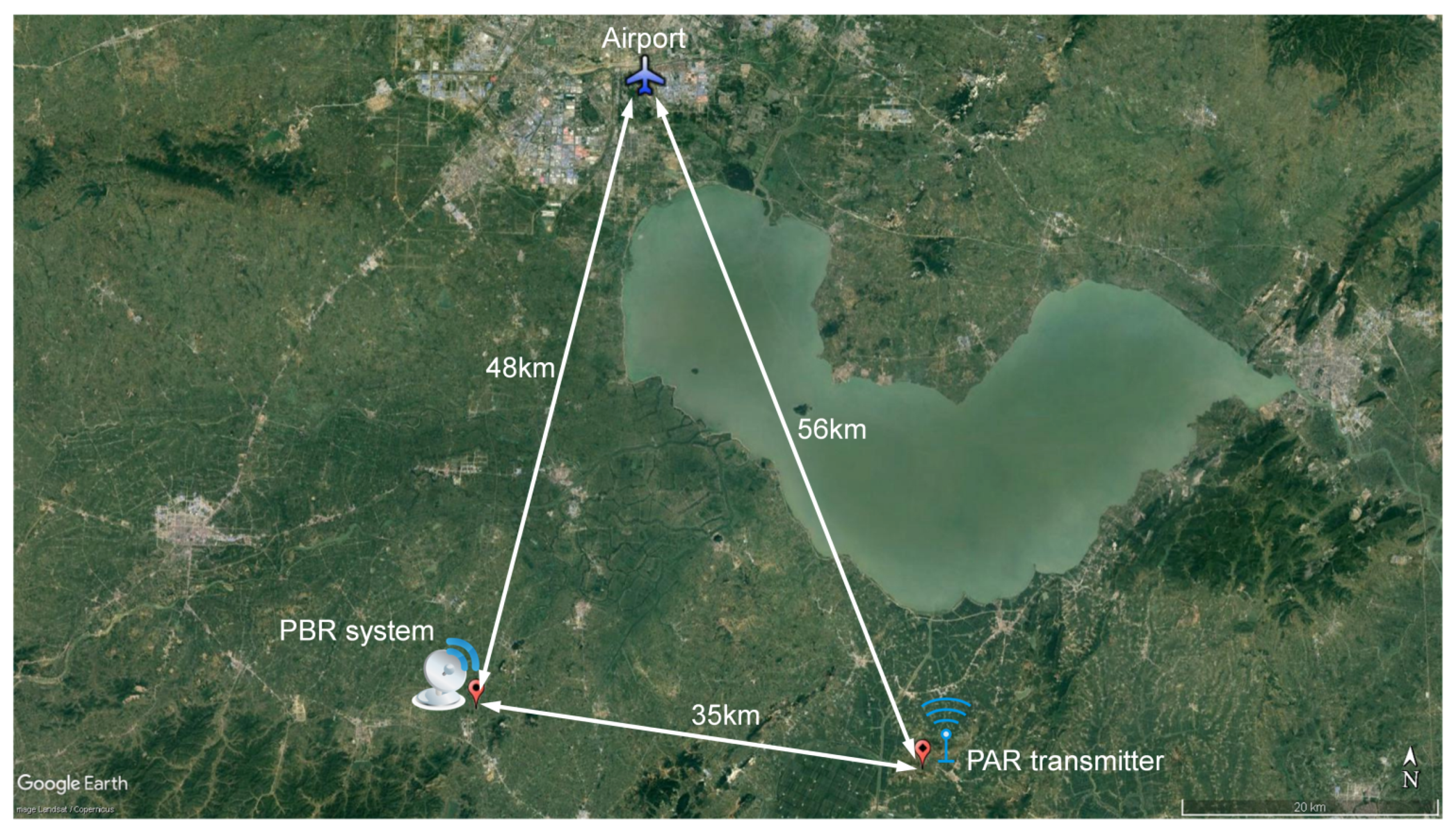
Figure 11 shows the experimental scenario geometry. The PAR transmitter and the PBR system are located at different locations, the distance between them is 35 km. There is a civil airport in the north of the PBR system with a distance of 48 km, thus ensuring the presence of aircraft targets in the air, which can be used to verify the target surveillance capability of the PBR system.
Based on a priori knowledge of the waveform of PAR signals, it can be concluded that there are 81 carrier frequency points of the transmitted signals, which vary from 558 MHz to 643 MHz. Therefore, a supersonic heterodyne receiver down-converts a high radio frequency (RF) signal from the reference antenna into intermediate frequencies (IF) signal by mixing the RF signal with a 600-MHz signal from a Local Oscillators (LO). 
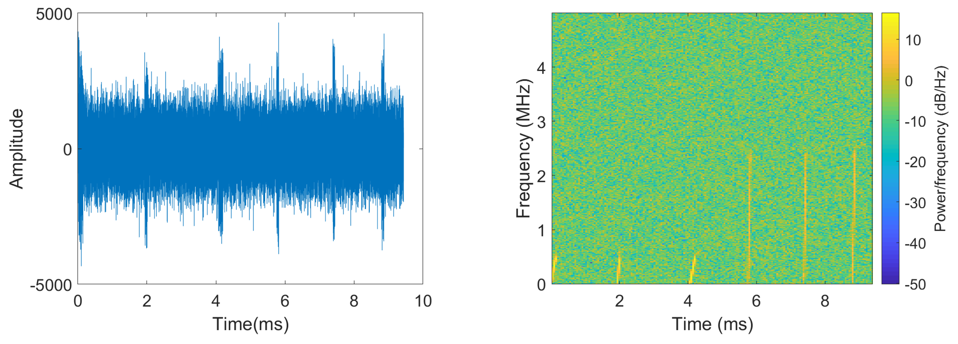
Figure 12 shows the imaginary part of the time domain signal and the spectrogram of direct wave IF signal.
It can be seen from Figure 12 that there are two groups of signals with different CF and BW and that the PRI and PW of different pulses in the same group are different. For direct wave signal, the CF, BW, and PW of the signal are obtained by the parameter estimation method described in Section 3 and the scattered wave signal received by the surveillance antenna is down-converted to baseband combined with the estimated CF. Figure 13 shows the imaginary part of the time domain signal and the spectrogram of the scattered wave baseband signal.
It can be seen that, although the surveillance antenna is not directed to the PAR transmitter, there are still direct wave signals in the surveillance channel, since the surveillance antenna can receive the sidelobe energy from the PAR emitter. However, it is obvious that the SNR of the direct wave in Figure 13 is much lower than that in Figure 12.
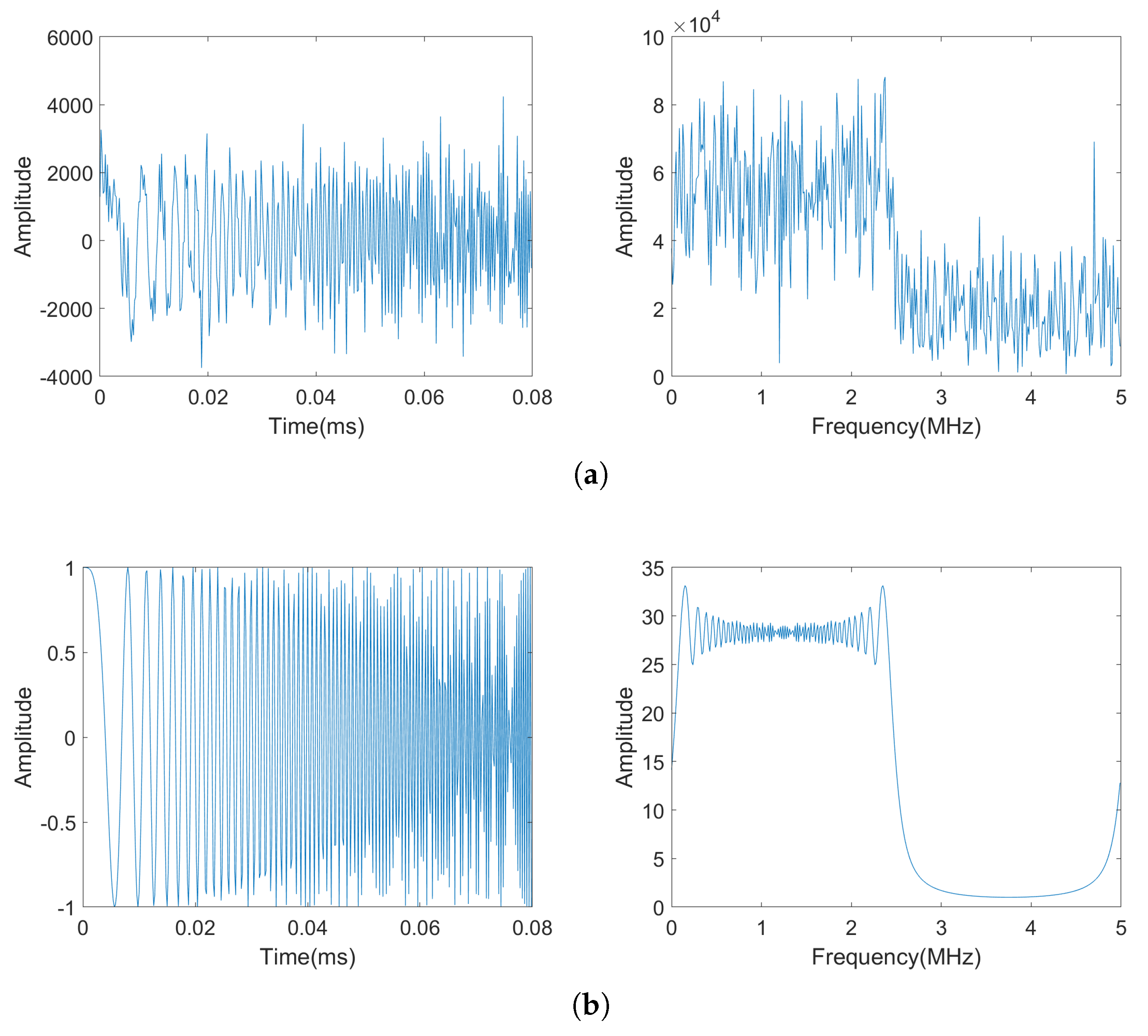
To verify the performance of matched filtering based on reconstructed reference signal, for the baseband signal in Figure 13, the last direct wave pulse signal is intercepted and the time-domain and frequency-domain signals are shown in Figure 14a, while the time-domain and frequency-domain plots of the reconstructed reference signal based on the parameters of the direct wave signal estimated in the reference channel are shown in Figure 14b, it can be seen that the SNR of the reconstructed reference signal is much higher.
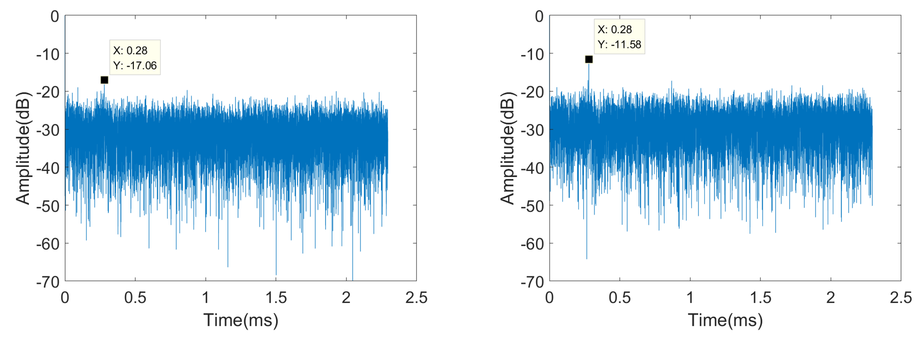
Then, the intercepted direct wave signal and the reconstructed reference signal are used for matched filtering of the whole echo signal, and the results are shown in Figure 15; it can be seen that the target echo has a higher SNR after matched filtering using the reconstructed reference signal.
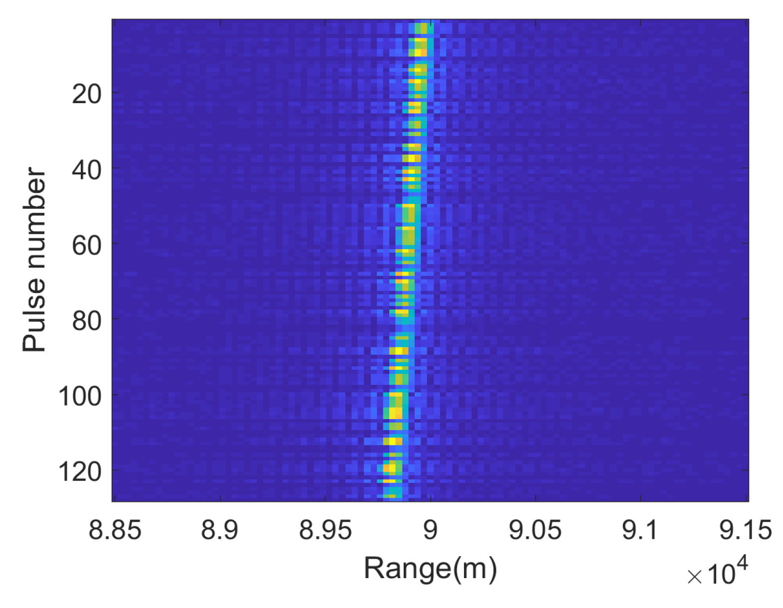
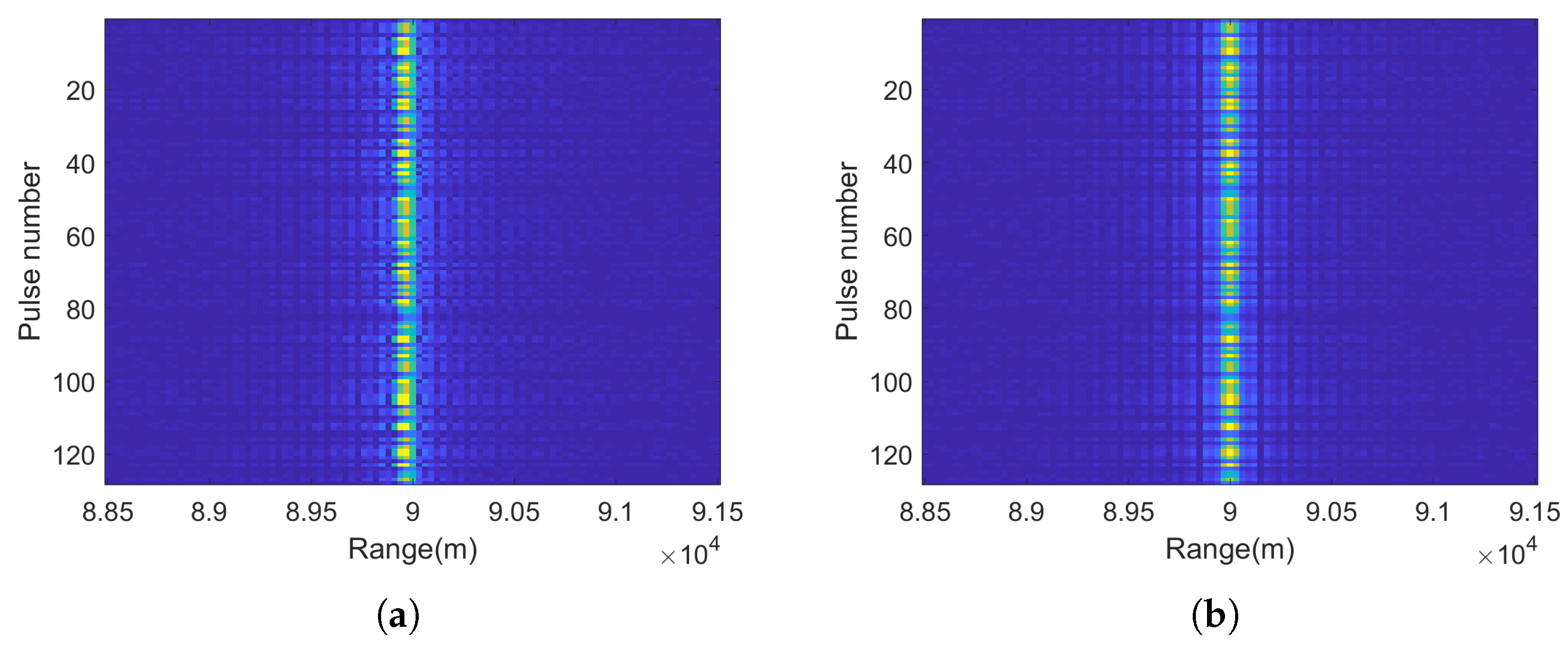
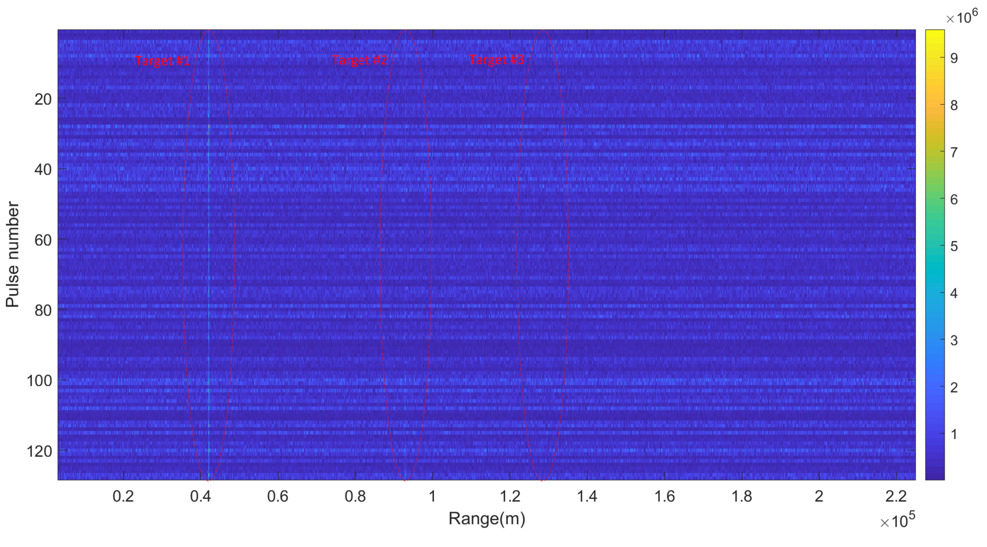
Since the CF and BW of the PAR signal are agile for different groups and a group of signal can last for a few seconds, we set 0.2 s as the CPI for the coherent integration of scattered wave signals. A total of 128 pulses in a CPI of the 4th beam are matched filtered and realigned according to the peak position of the direct wave signal, and the result is shown in Figure 16.
In 
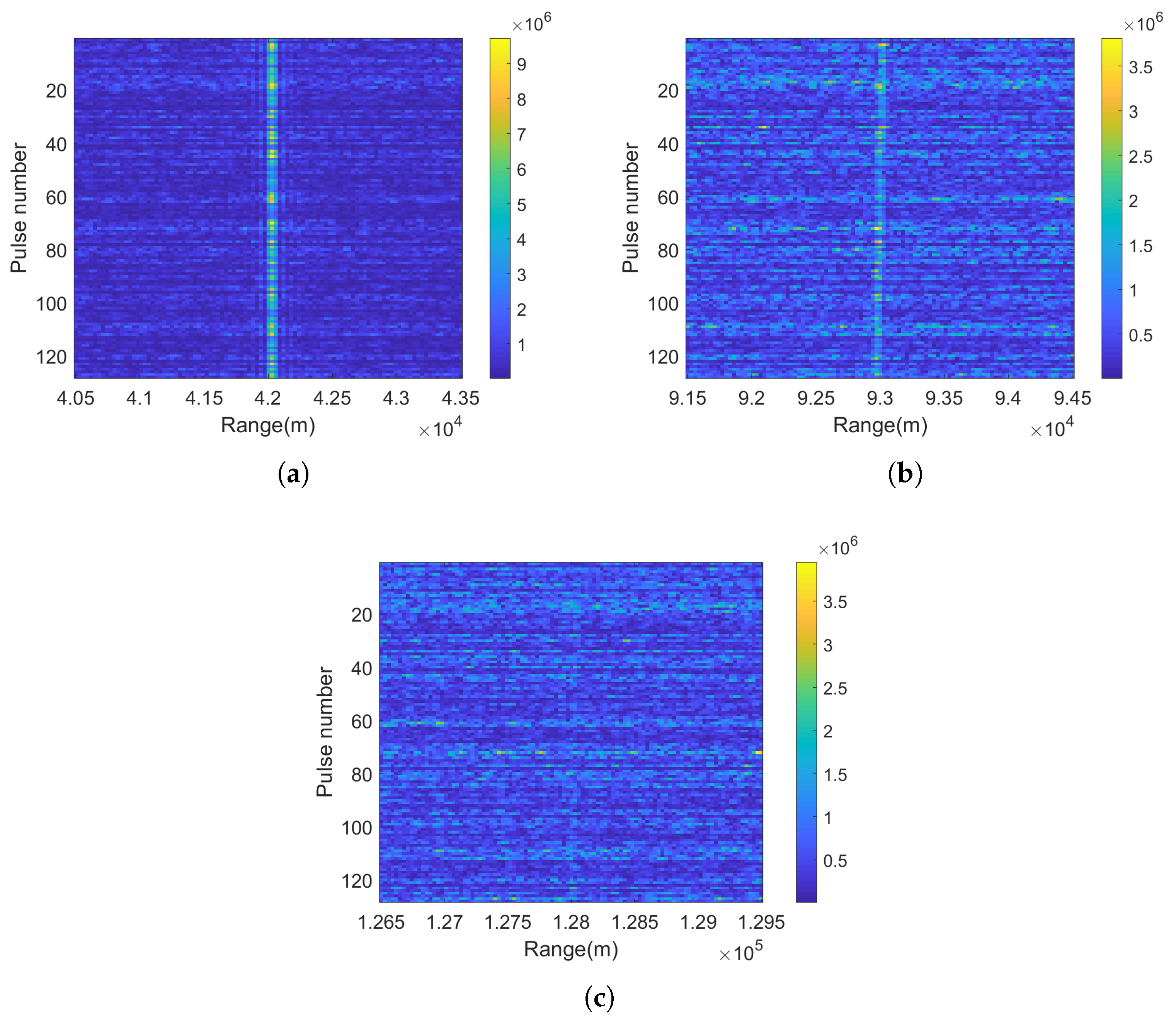
Figure 16, three trajectories of target can be faintly seen; then, they are intercepted and enlarged, which are shown in Figure 17.
It can be seen that the energy of the target echo is inversely proportional to its range, and since the PW of the signal is staggered, the energy of different echo signals after pulse compression are different. In addition, it is obvious that target #1 in Figure 17a is not moving, target #2 is a moving target since RCM occurs in Figure 17b, while the SNR of the target #3 is too low to judge whether it is moving. Therefore, the energy of the target echo should be accumulated by using the coherent integration method proposed in Section 4 so as to improve the detection probability of the target. Also, the velocity of targets can be estimated, thereby filtering out the fixed clutter.
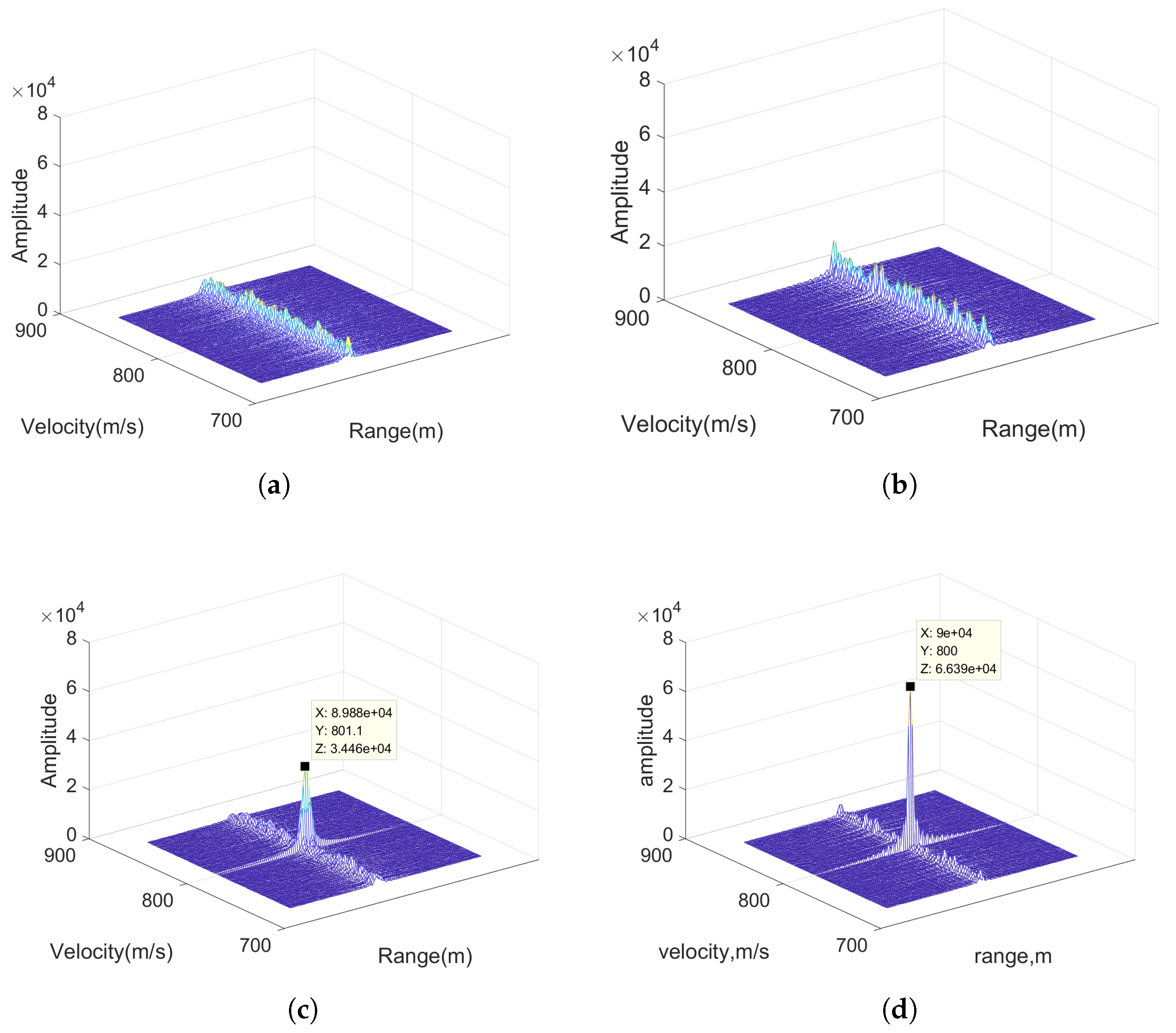
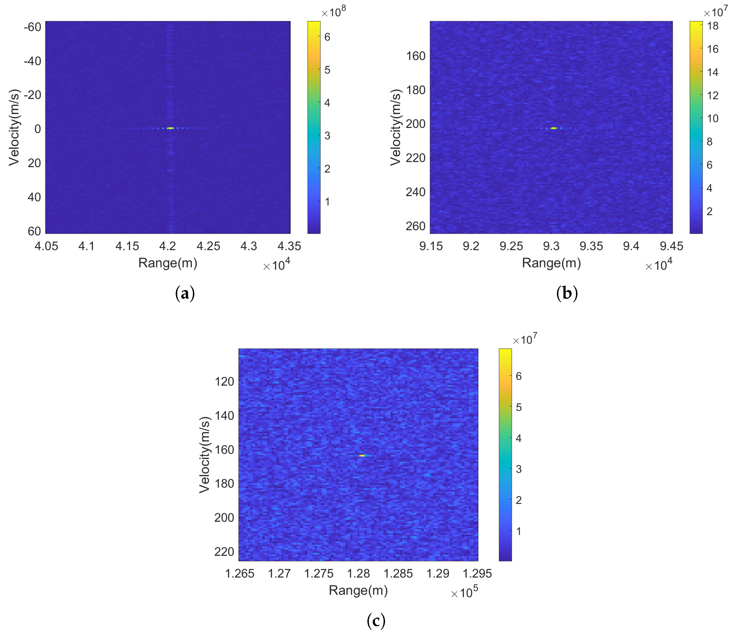
Figure 18 shows the results of coherent integration of the target echo in Figure 17 using the Radon-NUFFT method. According to Figure 18, the distance and velocity information of the three targets can be obtained as shown in Table 2.
Therefore, the motion parameters of the aircraft target can be effectively obtained by using the coherent integration method proposed in Section 4. After coherent integration and filtering of fixed clutter, CFAR detection is carried out for signals of different beams with a false alarm rate of 10 4 . After obtaining the target detection result, the target azimuth is obtained by amplitude comparison direction measurement. Finally, the distance between the target and the PBR system can be calculated according to Equation (2) combined with the bistatic range and the azimuth of the target, so the target positioning can be achieved afterwards.
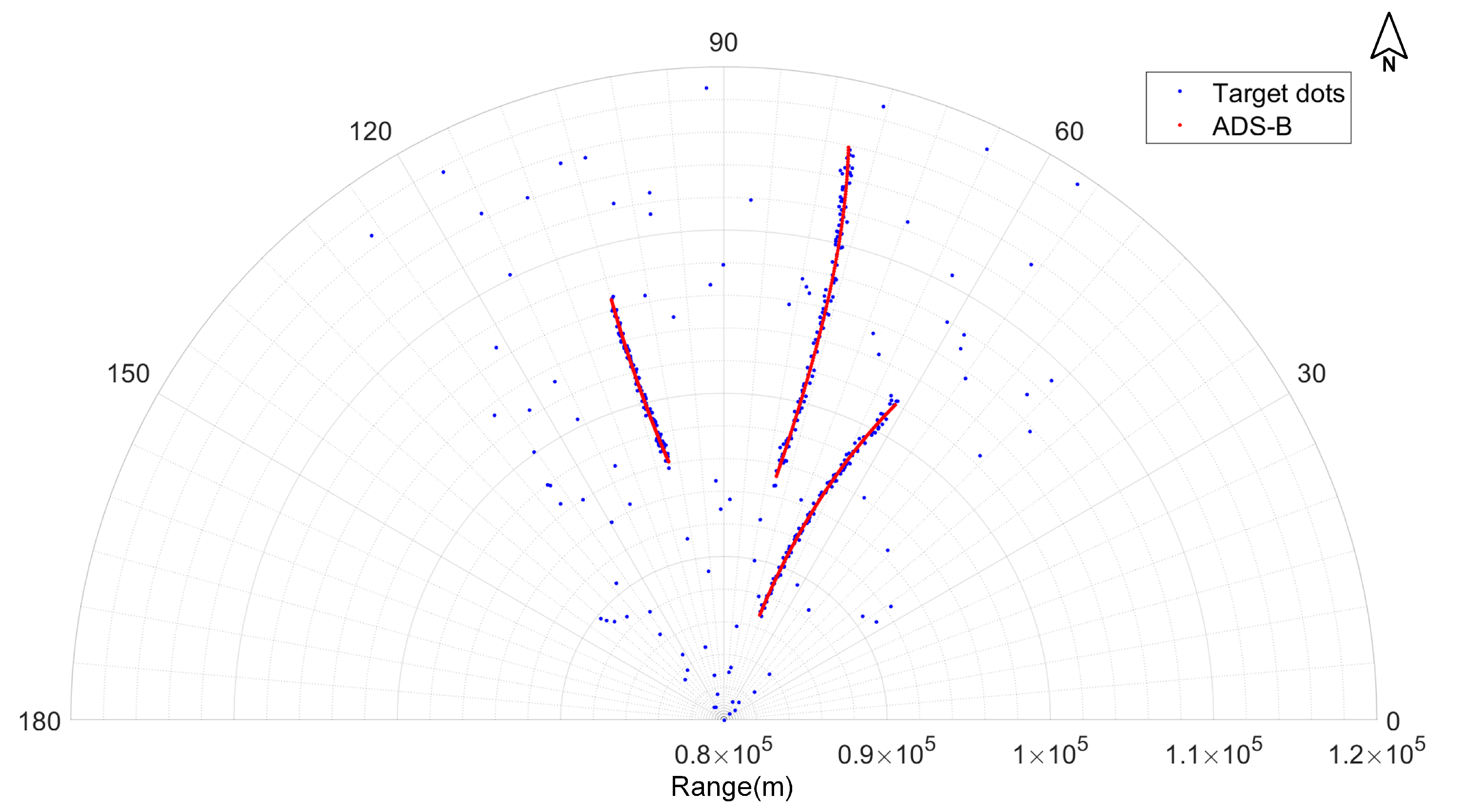
The target positioning results processed by PBR system for 120 s and target tracks converted from the real-time location information of flights provided by Automatic Dependent Surveillance-Broadcast (ADS-B) at the same time are drawn on the same figure to verify the target detection performance of the PBR system, which is shown in Figure 19.
It can be seen that the PBR system achieves the detection and localization of three moving aircraft targets effectively. There are some deviations between the target dots and the tracks provided by ADS-B since the error of target’s monostatic range depends on the target’s bistatic range and azimuth measurement errors at the same time. Moreover, it can be seen that there are some erroneous points far from the actual target tracks, which are false alarm points caused by clutter and noise; since these erroneous points are not continuous in time, they can be filtered out by the target tracking method, which will be explored in our future work. To validate the accuracy of the PBR system, we compare the monostatic distance and azimuth of the target dots near the three target tracks in 120 s with an actual target position, and the root mean square error (RMSE) of the distance and azimuth of the target dots can be calculated to be 984 m and 2 . 7 , respectively. It can be concluded that the PBR system based on PAR signals is able to locate the aircraft targets in the surveillance airspace.

6. Conclusions

In this paper, we conducted an experimental study to verify the feasibility of PBR based on PAR signals for aircraft target detection and localization. First, the experimental PBR system was described in general; after the analysis of the complex modulation form of PAR signals, two problems to be solved in signal processing were proposed, including the time and frequency synchronization of the PBR system and the coherent integration of radar signal with random PRI and staggered PW. Then, aiming at these two problems, the paper first proposed a direct wave parameter estimation method based on template matching to achieve a time and frequency synchronization of the PBR system and, then, proposes a coherent integration method based on Radon-NUFFT to deal with the irregular RCM and nonuniform phase fluctuations among different pulses caused by random PRI and the irregular range-Doppler coupling caused by staggered PW. Finally, the results of field experiments were presented. The performance of the matched filtering method based on reconstructed reference signal was verified by comparing the matched filtering results using different reference signals. The effectiveness of the coherent integration method based on Radon-NUFFT was verified by the coherent integration results of three targets. Finally, by comparing the target positioning results with the ADS-B tracks, the performance of target detection and localization of the PBR system based on PAR signals was verified.

Author Contributions

J.P. proposed and implemented the methods, Q.B. designed the experiment, J.P. and Q.Z. processed the data, and P.H. and Z.C. revised the manuscript. All authors of the article provided substantive comments.

Funding

This research received no external funding.

Conflicts of Interest

The authors declare no conflict of interest.

References

  1. Howland, P.; Maksimiuk, D.; Reitsma, G. FM radio based bistatic radar. IEE Proc. Radar Sonar Navig. 2005, 152, 107. [Google Scholar] [CrossRef]
  2. Honda, J.; Otsuyama, T. Feasibility Study on Aircraft Positioning by Using ISDB-T Signal Delay. IEEE Antennas Wireless Propag. Lett. 2016, 15, 1787–1790. [Google Scholar] [CrossRef]
  3. Langellotti, D.; Colone, F.; Lombardo, P.; Sedehi, M.; Tilli, E. DVB-T based Passive Bistatic Radar for maritime surveillance. In Proceedings of the IEEE Radar Conference, Cincinnati, OH, USA, 19–23 May 2014; pp. 1197–1202. [Google Scholar] [CrossRef]
  4. Bolvardi, H.; Derakhtian, M.; Sheikhi, A. Dynamic Clutter Suppression and Multitarget Detection in a DVB-T-Based Passive Radar. IEEE Trans. Aerosp. Electron. Syst. 2017, 53, 1812–1825. [Google Scholar] [CrossRef]
  5. Feng, W.; Friedt, J.M.; Cherniak, G.; Sato, M. Passive bistatic radar using digital video broadcasting–terrestrial receivers as general-purpose software-defined radio receivers. Rev. Sci. Instrum. 2018, 89, 104701. [Google Scholar] [CrossRef] [PubMed]
  6. Salah, A.; Abdullah, R.R.; Aziz, N.A.; Ismail, A.; Hashim, F. Experimental study of LTE signals as illuminators of opportunity for passive bistatic radar applications. Electron. Lett. 2014, 50, 545–547. [Google Scholar] [CrossRef]
  7. Falcone, P.; Colone, F.; Bongioanni, C.; Lombardo, P. Experimental results for OFDM WiFi-based passive bistatic radar. In Proceedings of the IEEE Radar Conference, Washington, DC, USA, 10–14 May 2010; pp. 516–521. [Google Scholar] [CrossRef]
  8. Clemente, C.; Soraghan, J.J. GNSS-Based Passive Bistatic Radar for Micro-Doppler Analysis of Helicopter Rotor Blades. IEEE Trans. Aerosp. Electron. Syst. 2014, 50, 491–500. [Google Scholar] [CrossRef]
  9. Harms, H.A.; Davis, L.M.; Palmer, J. Understanding the signal structure in DVB-T signals for passive radar detection. In Proceedings of the IEEE Radar Conference, Washington, DC, USA, 10–14 May 2010; pp. 532–537. [Google Scholar] [CrossRef]
  10. Griffiths, H.; Willis, N. Klein Heidelberg—The First Modern Bistatic Radar System. IEEE Trans. Aerosp. Electron. Syst. 2010, 46, 1571–1588. [Google Scholar] [CrossRef]
  11. Ito, T.; Takahashi, R.; Morita, S.; Hirata, K. Experimental result of passive bistatic radar with unknown transmitting radar pulse. In Proceedings of the European Microwave Conference, Nuremberg, Germany, 6–10 October 2013; pp. 1767–1770. [Google Scholar] [CrossRef]
  12. Samczynski, P.; Krysik, P.; Kulpa, K. Passive radars utilizing pulse radars as illuminators of opportunity. In Proceedings of the IEEE Radar Conference, Johannesburg, South Africa, 27–30 October 2015; pp. 168–173. [Google Scholar] [CrossRef]
  13. Wang, Y.; Bao, Q.; Wang, D.; Chen, Z. An Experimental Study of Passive Bistatic Radar Using Uncooperative Radar as a Transmitter. IEEE Geosci. Remote Sens. Lett. 2015, 12, 1868–1872. [Google Scholar] [CrossRef]
  14. Barbarossa, S. Analysis of multicomponent LFM signals by a combined Wigner-Hough transform. IEEE Trans. Signal Process. 1995, 43, 1511–1515. [Google Scholar] [CrossRef]
  15. Lv, X.; Bi, G.; Wan, C.; Xing, M. Lv’s Distribution: Principle, Implementation, Properties, and Performance. IEEE Trans. Signal Process. 2011, 59, 3576–3591. [Google Scholar] [CrossRef]
  16. Hao, H. Multi component LFM signal detection and parameter estimation based on EEMD–FRFT. Optik 2013, 124, 6093–6096. [Google Scholar] [CrossRef]
  17. Qian, L.; Xu, J.; Meng, C.; Li, J.; Zhou, X.; Long, T. Multi-waveform parameter estimation of external illuminator for passive bistatic radar. In Proceedings of the CIE International Conference on Radar (RADAR), Guangzhou, China, 10–13 October 2016; pp. 1–5. [Google Scholar] [CrossRef]
  18. Perry, R.P.; DiPietro, R.C.; Fante, R.L. Coherent Integration With Range Migration Using Keystone Formatting. In Proceedings of the IEEE Radar Conference, Boston, MA, USA, 17–20 April 2007; pp. 863–868. [Google Scholar] [CrossRef]
  19. Xu, J.; Yu, J.; Peng, Y.N.; Xia, X.G. Radon-Fourier Transform for Radar Target Detection, I: Generalized Doppler Filter Bank. IEEE Trans. Aerosp. Electron. Syst. 2011, 47, 1186–1202. [Google Scholar] [CrossRef]
  20. Rao, X.; Tao, H.; Su, J.; Guo, X.; Zhang, J. Axis rotation MTD algorithm for weak target detection. Digit. Signal Process. 2014, 26, 81–86. [Google Scholar] [CrossRef]
  21. Zheng, J.; Su, T.; Zhu, W.; He, X.; Liu, Q.H. Radar High-Speed Target Detection Based on the Scaled Inverse Fourier Transform. IEEE J. Sel. Topics Appl. Earth Observ. Remote Sens. 2014, 8, 1108–1119. [Google Scholar] [CrossRef]
  22. Babu, P.; Stoica, P. Spectral analysis of nonuniformly sampled data—A review. Digit. Signal Process. 2010, 20, 359–378. [Google Scholar] [CrossRef]
  23. Wu, Y.; Sepehri, N. Interpolation of bandlimited signals from uniform or non-uniform integral samples. Electron. Lett. 2011, 47, 53. [Google Scholar] [CrossRef]
  24. Li, J.; Chen, Z. Research on random PRI PD radar target velocity estimate based on NUFFT. In Proceedings of the 2011 IEEE CIE International Conference on Radar, Chengdu, China, 24–27 October 2011; Volume 2, pp. 1801–1803. [Google Scholar] [CrossRef]
  25. Tian, J.; Xia, X.G.; Cui, W.; Yang, G.; Wu, S.L. A Coherent Integration Method via Radon-NUFrFT for Random PRI Radar. IEEE Trans. Aerosp. Electron. Syst. 2017, 53, 2101–2109. [Google Scholar] [CrossRef]
  26. Pan, J.; Li, J.; Hu, P.; Bao, Q. Coherent integration method based on Radon-iterative adaptive approach for irregular pulse repetition interval radar. J. Appl. Remote Sens. 2019, 13, 016521. [Google Scholar] [CrossRef]
  27. Liu, Q.H.; Nguyen, N. An accurate algorithm for nonuniform fast Fourier transforms (NUFFT’s). IEEE Microw. Guid. Wave Lett. 1998, 8, 18–20. [Google Scholar] [CrossRef]
Figure 1. Geometry of the passive bistatic radar (PBR) system.
Electronics 08 00728 g001
Figure 2. Photographs of the reference antenna.
Electronics 08 00728 g002
Figure 3. High performance sampling module and signal processing platform.
Electronics 08 00728 g003
Figure 4. Flow chart of the signal processing method.
Electronics 08 00728 g004
Figure 5. Sketch map of simultaneously multi-beamforming.
Electronics 08 00728 g005
Figure 6. Flow chart of direct wave parameter estimation method.
Electronics 08 00728 g006
Figure 7. Flowchart of the proposed method.
Electronics 08 00728 g007
Figure 8. Range-time map after pulse compression.
Electronics 08 00728 g008
Figure 9. Results of signal after compensation. (a) Result after compensation of irregular RCM; (b) Result after compensation of irregular RCM and range-Doppler coupling.
Electronics 08 00728 g009
Figure 10. Coherent integration via four method: (a) MTD, (b) RFT, (c) NUFFT among slow time, (d) Radon-NUFFT.
Electronics 08 00728 g010
Figure 11. The experimental scenario geometry.
Electronics 08 00728 g011
Figure 12. Time domain waveform and spectrogram of direct wave IF signal.
Electronics 08 00728 g012
Figure 13. Time domain waveform and spectrogram of scattered wave baseband signal.
Electronics 08 00728 g013
Figure 14. Time-domain and frequency-domain plots of the intercepted direct wave signal and reconstructed reference signal. (a) Intercepted direct wave signal; (b) Reconstructed reference signal
Electronics 08 00728 g014
Figure 15. Results of matched filtering using intercepted direct wave signal and reconstructed reference signal.
Electronics 08 00728 g015
Figure 16. Time-range map after pulse compression and realignment.
Electronics 08 00728 g016
Figure 17. Time-range map of three targets.
Electronics 08 00728 g017
Figure 18. Coherent integration results of three targets.
Electronics 08 00728 g018
Figure 19. Result of target positioning and Automatic Dependent Surveillance-Broadcast (ADS-B) tracks.
Electronics 08 00728 g019
Table 1. Simulated parameters.
System Parameters (Unit)Values
Carrier frequency (MHz)680
Bandwidth (MHz)2
Sampling frequency (MHz)5
Pulse width template library (us){40 80 120 160 200}
Average PRI (us)1500
Variation range of PRI (us)[1000 2000]
Number of coherently integrated pulses128
Initial distance of target (km)90
Radial velocity of target (m/s)800
Table 2. Motion parameters of the targets.
Target NumberDistance (km)Velocity (m/s)
#142.030.98
#293.06203
#3128.03164

