High-Isolation Leaky-Wave Array Antenna Based on CRLH-Metamaterial Implemented on SIW with ±30o Frequency Beam-Scanning Capability at Millimetre-Waves

 ,
, 
 ,
,  ,
,  and
and 
Abstract
:1. Introduction
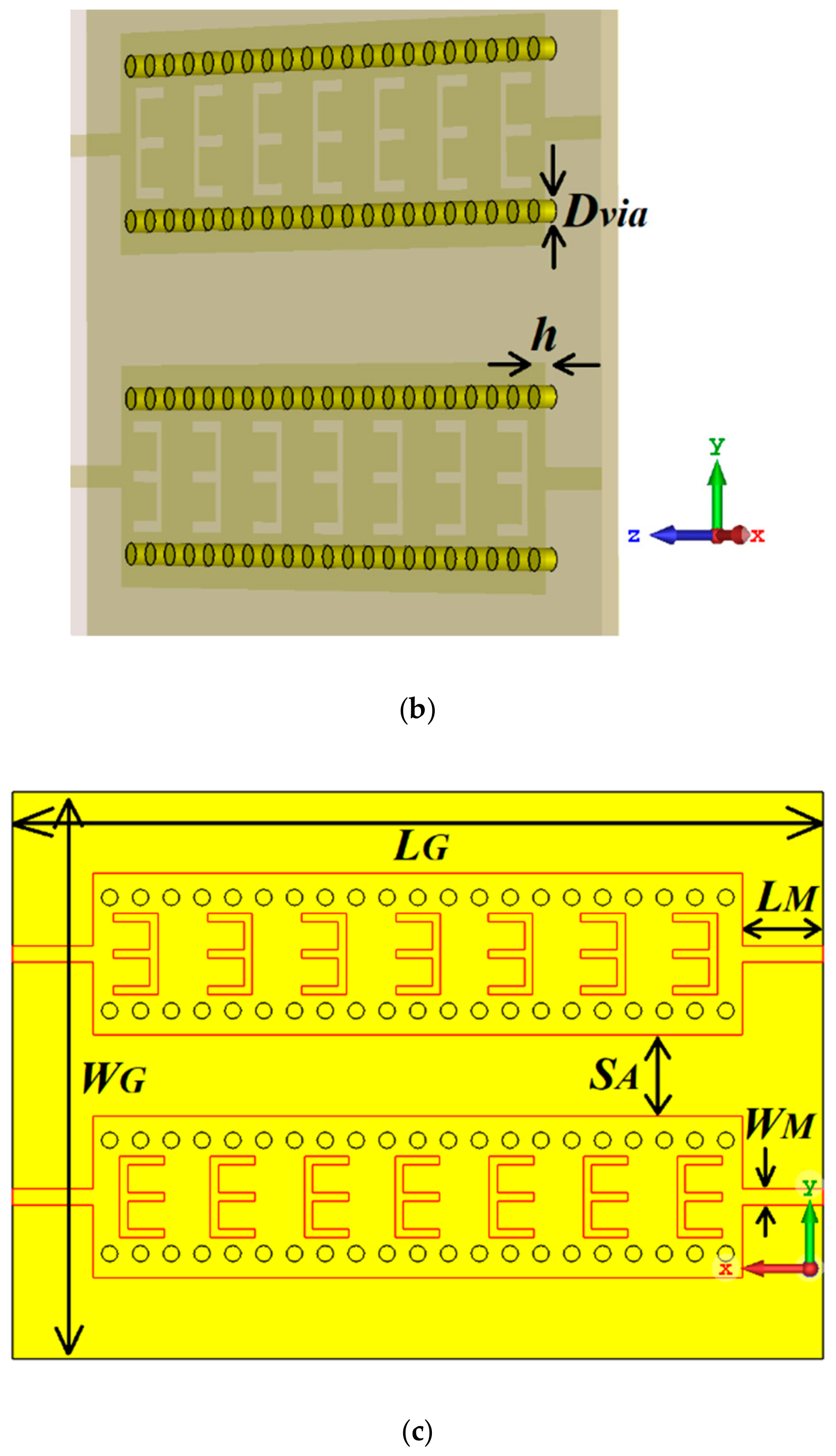
2. Design Process of The Proposed Mtm-Lwa Array Based On Siw
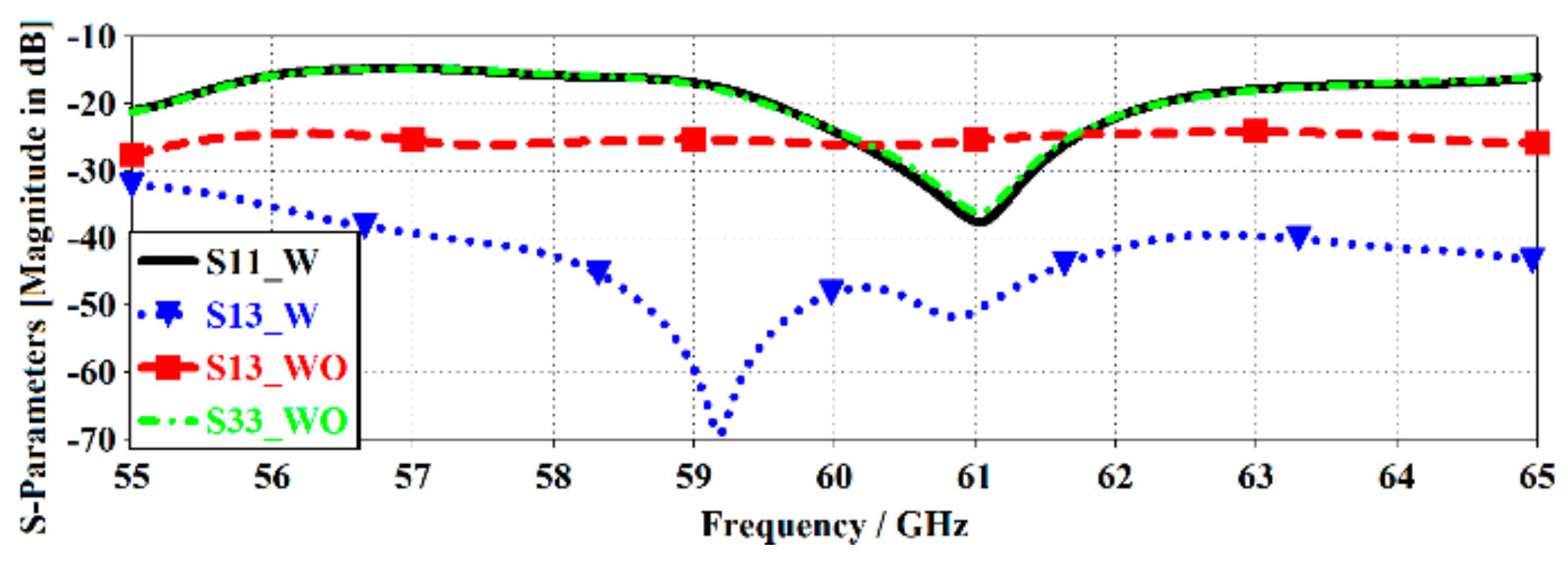
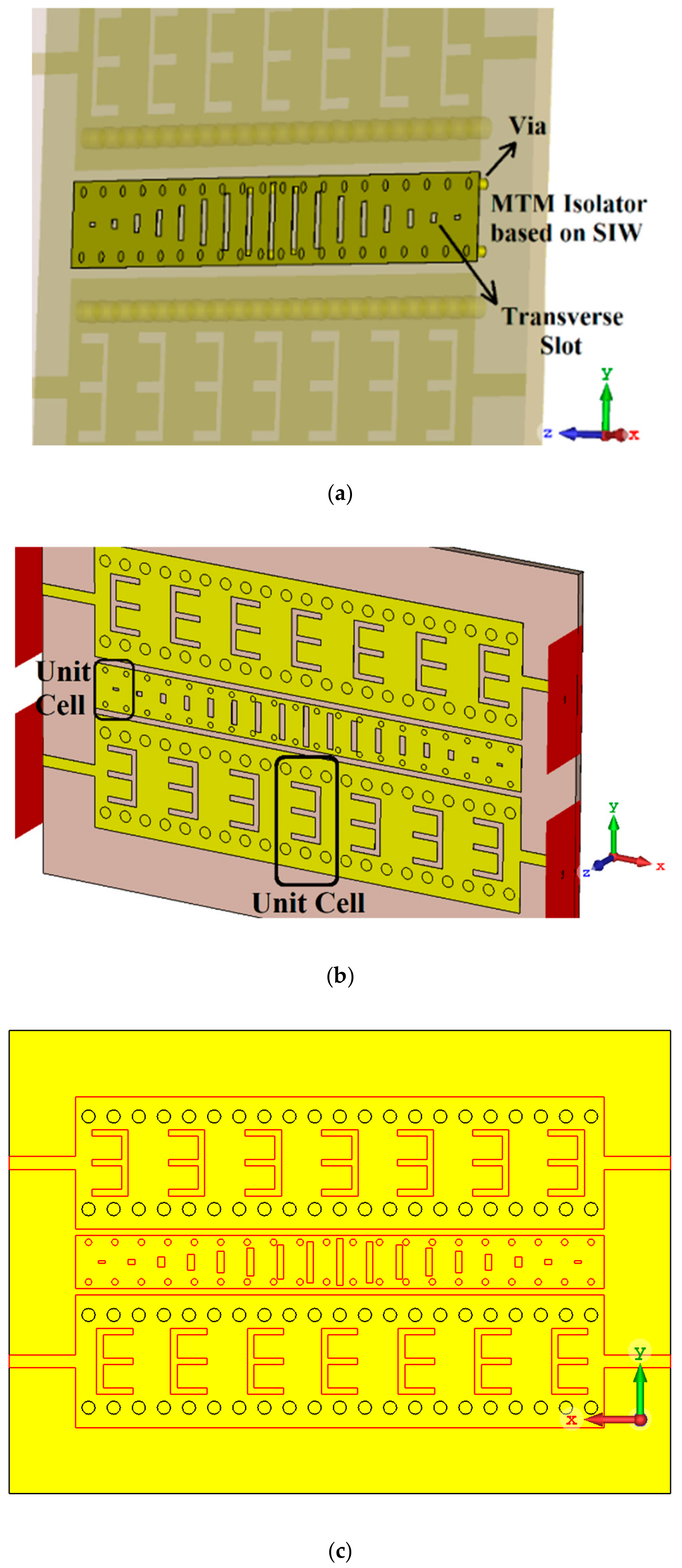
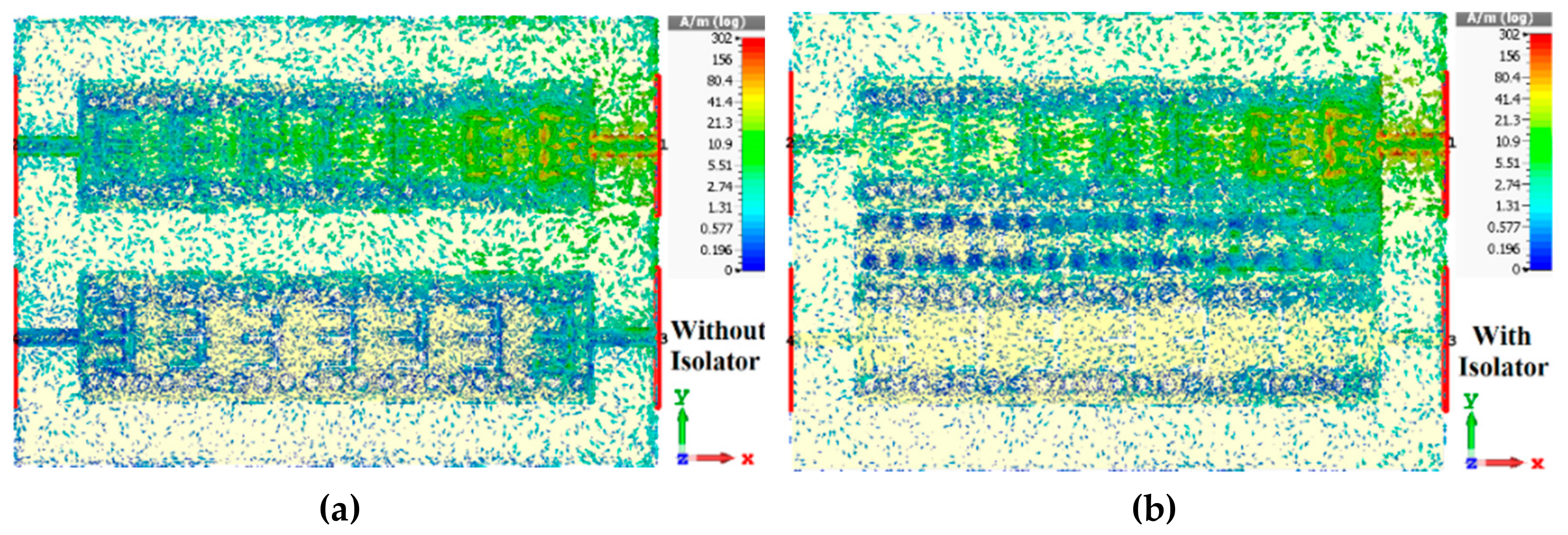
3. Suppress the Mutual Coupling Between the Closely Spaced Mtm-Lwa Arrays
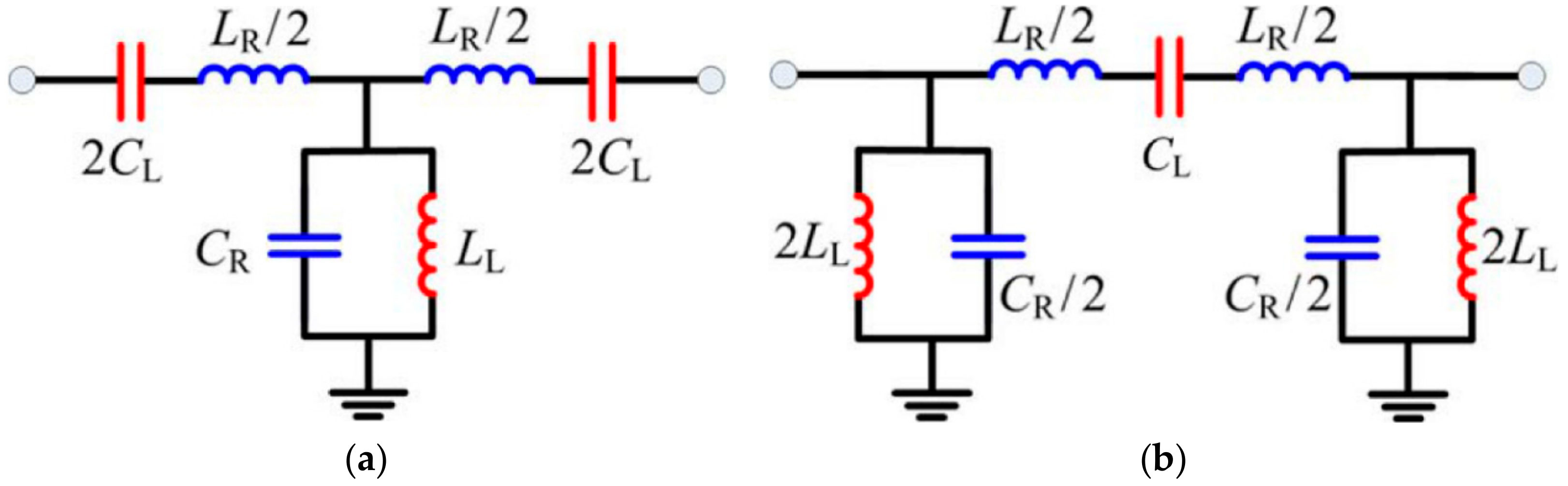
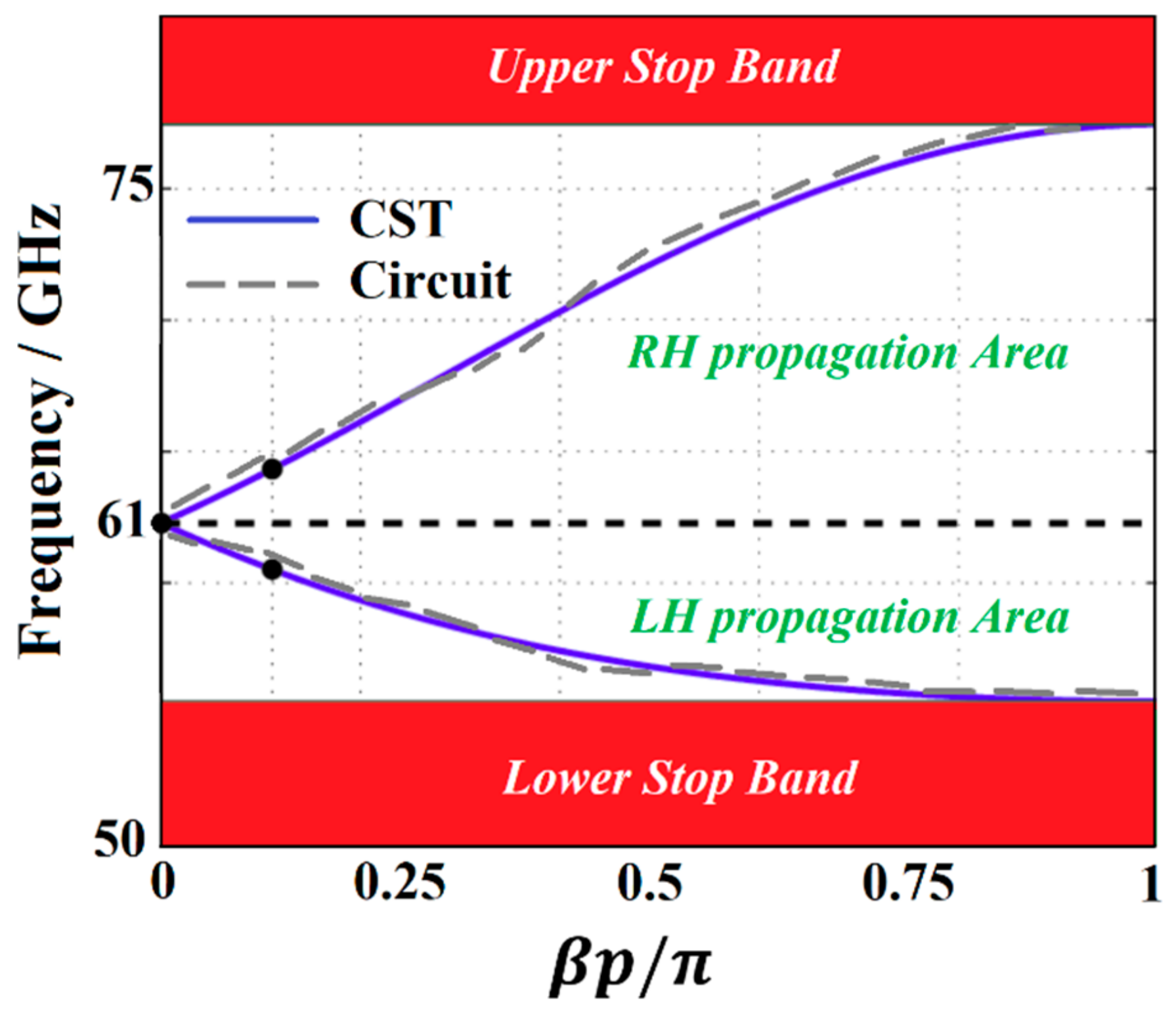
4. Circuit Model of The Proposed MTM-Lwa Array and its Dispersion Phenomenon
5. Comparison between This Work and The Literature
6. Conclusion
Author Contributions
Funding
Conflicts of Interest
References
- Jackson, D.R.; Oliner, A.A. Leaky-wave antennas. In Modern Antenna Handbook; John Wiley & Sons: New York, NY, USA, 2008; pp. 325–367. [Google Scholar]
- Sievenpiper, D.F. Forward and backward leaky wave radiation with large effective aperture from an electronically tunable textured surface. IEEE Trans. Antennas Propag. 2005, 53, 236–247. [Google Scholar] [CrossRef]
- Jackson, D.R.; Caloz, C.; Itoh, T. Leaky-wave antennas. Proc. IEEE 2012, 100, 2194–2206. [Google Scholar] [CrossRef]
- Lim, S.; Caloz, C.; Itoh, T. Metamaterial-based electronically controlled transmission-line structure as a novel leaky-wave antenna with tunable radiation angle and beamwidth. IEEE Trans. Microw. Theory Tech. 2004, 52, 2678–2690. [Google Scholar] [CrossRef]
- Caloz, C.; Itoh, T.; Rennings, A. CRLH metamaterial leaky-wave and resonant antennas. IEEE Antennas Propag. Mag. 2008, 50, 25–39. [Google Scholar] [CrossRef]
- Paulotto, S.; Baccarelli, P.; Frezza, F.; Jackson, D.R. A novel technique for open-stopband suppression in 1-D periodic printed leaky-wave antennas. IEEE Trans. Antennas Propag. 2009, 57, 1894–1906. [Google Scholar] [CrossRef]
- Chen, Z.N.; Qing, X. Slotted SIW Leaky-Wave Antenna with Improved Backward Scanning Bandwidth and Consistent Gain. In Proceedings of the 2017 11th European Conference on Antennas and Propagation (EUCAP), Paris, France, 19–24 March 2017; pp. 752–755. [Google Scholar]
- Qian, Y.; Chang, B.C.C.; Itoh, T.; Chen, K.C.; Tzuang, C.K.C. High efficiency and broadband excitation of leaky mode in microstrip structures. In Proceedings of the 1999 IEEE MTT-S International Microwave Symposium Digest (Cat. No.99CH36282), Anaheim, CA, USA, 13–19 June 1999; pp. 1419–1422. [Google Scholar]
- Caloz, C.; Itoh, T. Electromagnetic Metamaterials: Transmission Line Theory and Microwave Applications; Wiley-IEEE Press: New York, NY, USA, 2005; 376p. [Google Scholar]
- Yang, T.; Chi, P.L.; Xu, R.M. Novel composite right/left-handed leaky-wave antennas based on the folded substrate-integrated waveguide structures. Prog. Electromagn. Res. 2012, 29, 235–248. [Google Scholar] [CrossRef]
- Dong, Y.; Itoh, T. Composite right/left-handed substrate integrated waveguide and half mode substrate integrated waveguide leaky-wave structures. IEEE Trans. Antennas Propag. 2011, 59, 767–775. [Google Scholar] [CrossRef]
- Weitsch, Y.; Eibert, T.F. Analysis and design of a composite left/right-handed leaky wave antenna based on the H10 rectangular waveguide mode. Adv. Radio Sci. 2008, 6, 49–54. [Google Scholar] [CrossRef]
- Chen, Z.N.; Qing, X. Multilayered composite right/left-handed leaky-wave antenna with consistent gain. IEEE Trans. Antennas Propag. 2012, 60, 5056–5062. [Google Scholar]
- Lai, A.; Leong, K.M.; Itoh, T. Infinite wavelength resonant antennas with monopolar radiation pattern based on periodic structures. IEEE Trans. Antennas Propag. 2007, 55, 868–876. [Google Scholar] [CrossRef]
- Dong, Y.; Itoh, T. Miniaturized substrate integrated waveguide slot antennas based on negative order resonance. IEEE Trans. Antennas Propag. 2010, 58, 3856–3864. [Google Scholar] [CrossRef]
- Dong, Y.; Itoh, T. Substrate integrated waveguide negative order resonances and their applications. IEEE Trans. Antennas Propag. 2010, 4, 1081–1091. [Google Scholar] [CrossRef]
- Dong, Y.; Itoh, T. Metamaterial-Based Antennas. Proc. IEEE 2012, 100, 2271–2285. [Google Scholar] [CrossRef]
- Johnson, R.C.; Jasik, H. Antenna Engineering Handbook, 4th ed.; McGraw-Hill Education: New York, NY, USA, 2007. [Google Scholar]
- Mohsen, M.K.; Isa, M.S.M.; Isa, A.A.M.; Zin, M.S.I.M.; Saat, S.; Zakaria, Z.; Ibrahim, I.M.; Abu, M.; Ahmad, A.; Abdulhameed, M.K. The Fundamental of Leaky Wave Antenna. J. Telecommun. Electron. Comput. Eng. 2018, 10, 19–127. [Google Scholar]
- Frank, B.G. Frontiers in Antennas: Next Generation Design & Engineering; McGraw Hill Professional: New York, NY, USA, 2010; 512p. [Google Scholar]
- Bait-Suwailam, M.M.; Siddiqui, O.F.; Ramahi, O.M. Mutual coupling reduction between microstrip patch antennas using slotted-complementary split-ring resonators. IEEE Antennas Wirel. Prop. Lett. 2010, 9, 876–878. [Google Scholar] [CrossRef]
- Shafique, M.F.; Qamar, Z.; Riaz, L.; Saleem, R.; Khan, S.A. Coupling suppression in densely packed microstrip arrays using metamaterial structure. Microw. Opt. Tech. Lett. 2015, 57, 759–763. [Google Scholar] [CrossRef]
- Islam, M.T.; Alam, M.S. Compact EBG Structure for Alleviating Mutual Coupling between Patch Antenna Array Elements. Prog. Electromagn. Res. 2013, 137, 425–438. [Google Scholar] [CrossRef]
- Alibakhshikenari, M.; Virdee, B.S.; See, C.H.; Abd-Alhameed, R.; Ali, A.H.; Falcone, F.; Limiti, E. Study on Isolation Improvement Between Closely Packed Patch Antenna Arrays Based on Fractal Metamaterial Electromagnetic Bandgap Structures. IET Microw. Ant. Propag. 2018, 12, 2241–2247. [Google Scholar] [CrossRef]
- Ghosh, T.; Ghosal, S.; Mitra, D.; Bhadra Chaudhuri, S.R. Mutual Coupling Reduction Between Closely Placed Microstrip Patch Antenna Using Meander Line Resonator. Prog. Electromag. Res. Lett. 2016, 59, 115–122. [Google Scholar] [CrossRef]
- Yang, F.; Rahmat-Samii, Y. Microstrip Antennas Integrated with Elctromagnetic Band-Gap (EBG) Structures: A Low Mutual Coupling Design for Array Applications. IEEE Trans. Antennas Propag. 2003, 51, 2936–2946. [Google Scholar] [CrossRef]
- Mu’ath, J.; Denidni, T.A.; Sebak, A.R. Millimeter Wave Compact EBG Structure for Mutual Coupling Reduction Applications. IEEE Trans. Antennas Propag. 2015, 63, 823–828. [Google Scholar]
- Liu, J.; Jackson, D.R.; Long, Y. Substrate integrated waveguide (SIW) leaky-wave antenna with transverse slots. IEEE Trans. Antennas Propag. 2012, 60, 20–29. [Google Scholar] [CrossRef]
- Ettorre, M.; Sauleau, R.; Le Coq, L. Multi-beam multi-layer leaky-wave SIW pillbox antenna for millimeter-wave applications. IEEE Trans. Antennas Propag. 2011, 59, 1093–1100. [Google Scholar] [CrossRef]
- Taravati, S.; Caloz, C. Mixer-duplexer-antenna leaky-wave system based on periodic space-time modulation. IEEE Trans. Antennas Propag. 2017, 65, 442–452. [Google Scholar] [CrossRef]
- Taravati, S.; Caloz, C. Space-time modulated nonreciprocal mixing, amplifying and scanning leaky-wave antenna system. In Proceedings of the 2015 IEEE International Symposium on Antennas and Propagation & USNC/URSI National Radio Science Meeting, Vancouver, BC, Canada, 19–24 July 2015; pp. 639–640. [Google Scholar]
- Alibakhshikenari, M.; Virdee, B.S.; Shukla, P.; See, C.H.; Abd-Alhameed, R.; Khalily, M.; Falcone, F.; Limiti, E. Interaction Between Closely Packed Array Antenna Elements Using Metasurface for Applications Such as MIMO Systems and Synthetic Aperture Radars. Radio Sci. 2018, 53, 1368–1381. [Google Scholar] [CrossRef]
- Yang, X.; Liu, Y.; Xu, Y.X.; Gong, S.X. Isolation Enhancement in Patch Antenna Array with fractal UC-EBG Structure and Cross Slot. IEEE Antennas Wirel. Propag. Lett. 2017, 16, 2175–2178. [Google Scholar] [CrossRef]
- Alsath, M.G.N.; Kanagasabai, M.; Balasubramanian, B. Implementation of Slotted Meander Line Resonators for Isolation Enhancement in Microstrip Patch Antenna Arrays. IEEE Antennas Wirel. Propag. Lett. 2013, 12, 15–18. [Google Scholar] [CrossRef]
- Alibakhshikenari, M.; Virdee, B.; Shukla, P.; See, C.; Abd-Alhameed, R.; Khalily, M.; Falcone, F.; Limiti, E. Antenna Mutual Coupling Suppression Over Wideband Using Embedded Periphery Slot for Antenna Arrays. Electronics 2018, 7, 198. [Google Scholar] [CrossRef]
- Ghosh, C.K.; Parui, S.K. Reduction of Mutual Coupling Between E-Shaped Microstrip Antennas by Using a Simple Microstrip I-Section. Microw. Opt. Tech. Lett. 2013, 55, 2544–2549. [Google Scholar] [CrossRef]
- Qamar, Z.; Park, H.C. Compact Waveguided Metamaterials for Suppression of Mutual Coupling in Microstrip Array. Prog. Electromagn. Res. 2014, 149, 183–192. [Google Scholar] [CrossRef]
- Alibakhshikenari, M.; See, C.H.; Virdee, B.S.; Abd-Alhameed, R.A. Meta-surface Wall Suppression of Mutual Coupling between Microstrip Patch Antenna Arrays for THz-band Applications. Prog. Electromagn. Res. Lett. 2018, 75, 105–111. [Google Scholar] [CrossRef]
- Qamar, Z.; Naeem, U.; Khan, S.A. Mutual coupling reduction for high performance densely packed patch antenna arrays on finite substrate. IEEE Trans. Antennas Propag. 2016, 64, 1653–1660. [Google Scholar] [CrossRef]
- Qamar, Z.; Riaz, L.; Chongcheawchamnan, M.; Khan, S.A.; Shafique, M.F. Slot combined complementary split ring resonators for mutual coupling suppression in microstrip phased arrays. IET Microw. Antenna Propag. 2014, 8, 1261–1267. [Google Scholar] [CrossRef]
- Alibakhshikenari, M.; Khalily, M.; Virdee, B.S.; See, C.H.; Abd-Alhameed, R.A.; Limiti, E. Mutual-Coupling Isolation Using Embedded Metamaterial EM Bandgap Decoupling Slab for Densely Packed Array Antennas. IEEE Access 2019, 7, 5182–51840. [Google Scholar] [CrossRef]
- Alibakhshikenari, M.; Khalily, M.; Virdee, B.S.; See, C.H.; Abd-Alhameed, R.A.; Limiti, E. Mutual Coupling Suppression Between Two Closely Placed Microstrip Patches Using EM-Bandgap Metamaterial Fractal Loading. IEEE Access 2019, 7, 23606–23614. [Google Scholar] [CrossRef]


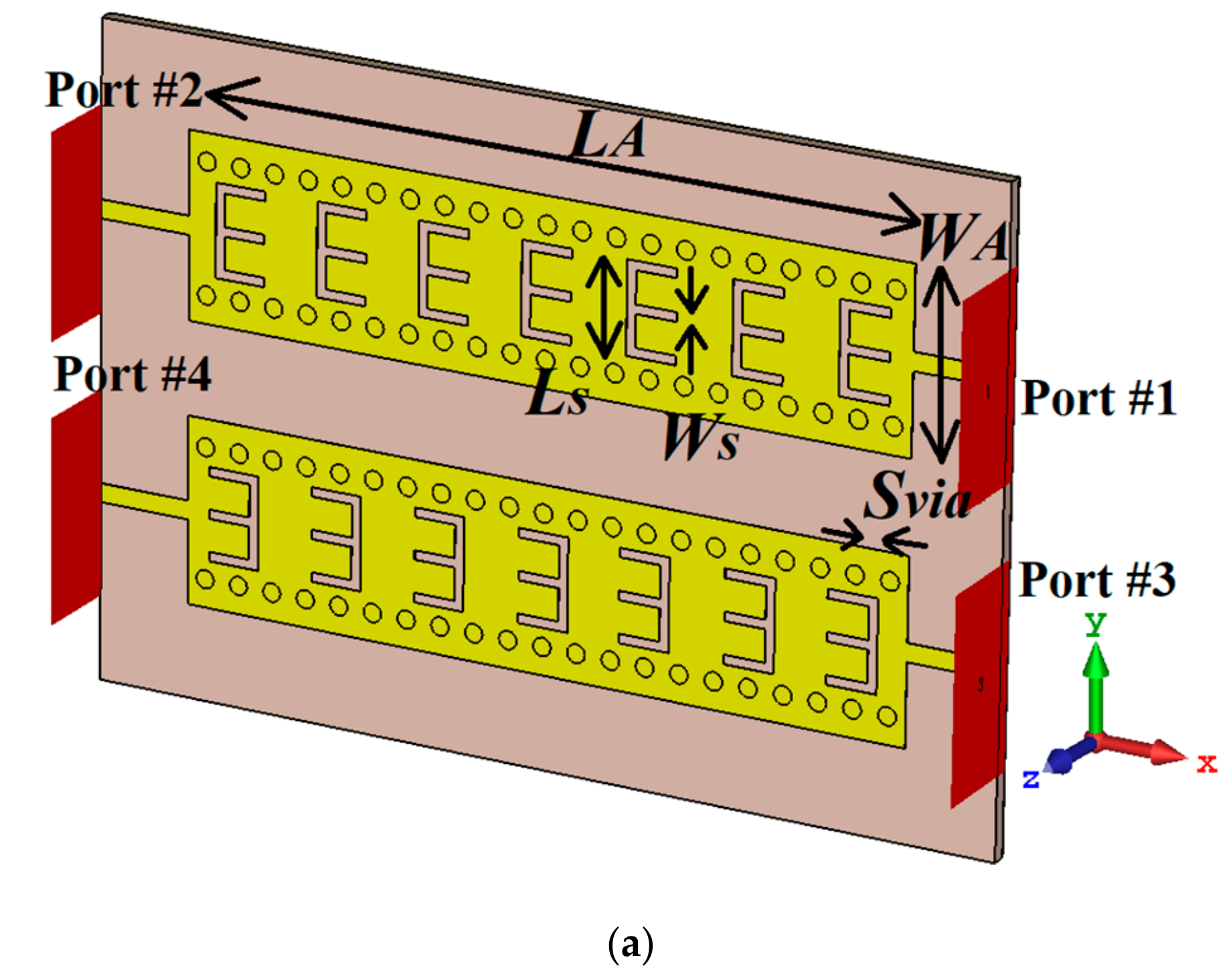
| Structural Parameters | Dimensions (Units in mm) |
|---|---|
| LALA | 40 |
| WAWA | 10 |
| LGLG | 50 |
| WGWG | 35 |
| LSLS | 5 |
| WSWS | 0.5 |
| DviaDvia | 0.5 |
| SviaSvia | 0.5 |
| SASA | 5 |
| LMLM | 5 |
| WMWM | 1 |
| hh | 0.75 |
| Radiation Gain | ||
|---|---|---|
| Without MTM | With MTM | |
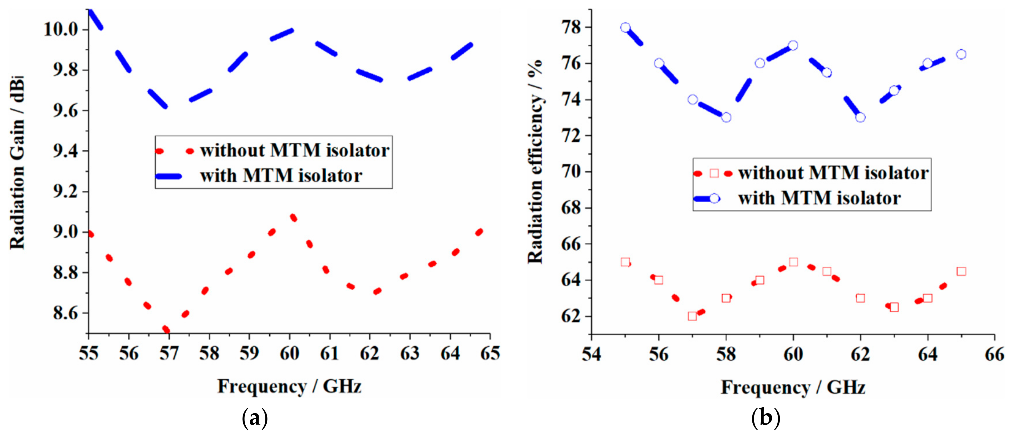
| Minimum | 8.69 dBi | 9.6 dBi |
| Maximum | 9.11 dBi | 10.16 dBi |
| Average | 8.90 dBi | 9.86 dBi |
| Improvement in Average | ~1 dBi | |
| Radiation Efficiency | ||
| Without MTM | With MTM | |
| Minimum | 62.53% | 73.44% |
| Maximum | 65.21% | 78.12% |
| Average | 63.5% | 76.38 |
| Improvement in Average | ~13% | |
| Ref. | Method | Max. Isolation Improvement | Bandwidth (FBW) | Rad. Gain Pattern Deterioration | No. of Elements | Application of DGS | Symmetry and Simplicity |
|---|---|---|---|---|---|---|---|
| [21] | SCSRR | 10 dB | Narrow | Yes | 2 | Yes | No |
| [22] | SCSSRR | 14.6 dB | Narrow | Yes | 2 | Yes | No |
| [23] | Compact EBG | 17 dB | Narrow | Yes | 2 | Yes | No |
| [24] | Fractal MTM-EMBG | 37 dB | Wide (~15%) | No | 4 | No | Yes |
| [25] | Meander Line | 10 dB | Narrow | No | 2 | Yes | No |
| [26] | EBG | 8.8 dB | Narrow | - | Yes | No | |
| [27] | EBG | 13 dB | Wide (~12%) | Yes | 2 | Yes | No |
| [28] | Substrate Integrated Waveguide (SIW) with Transverse Slots | 15 dB | Wide (22.22%) | - | 1 | No | Yes |
| [29] | Substrate Integrated Waveguide (SIW) and Slots | 20 dB | Wide (16.32%) | - | 1 | No | Yes |
| [30] | Periodic Space-Time Modulation | - | Wide (58.82%) | - | 1 | No | Yes |
| [31] | Space Time Modulation (External Linear Momentum) | - | - | - | 1 | No | Yes |
| [32] | MTM-DS | 57 dB | Wide | No | 2 | No | Yes |
| [33] | Fractal load + DGS | 16 dB | Narrow (2.5%) | No | 2 | Yes | No |
| [34] | Slotted Meander-Line | 16 dB | Narrow | Yes | 2 | Yes | No |
| [35] | Slots | >26 dB | Wide | No | 4 | No | Yes |
| [36] | I-Shaped Resonator | 30dB | Narrow | Yes | 2 | Yes | No |
| [37] | W/g MTM | 18 dB | Narrow | No | 2 | Yes | No |
| [38] | MSWI | 13.5 dB | Wide | No | 2 | No | Yes |
| [39] | Metamaterial Superstrate | 25 | Narrow | No | 2 | No | Yes |
| [40] | Slot Combined Complementary Split Ring Resonator | 19 | Narrow | Yes | 2 | No | No |
| [41] | Metamaterial | 40 | Wide (8.8%) | No | 4 | No | Yes |
| [42] | Fractal Load | 37 | Wide | No | 2 | No | Yes |
| This work | Metamaterials and Substrate Integrated Waveguide | 42.5 dB | Wide (16.66%) | No | 2 | No | Yes |
© 2019 by the authors. Licensee MDPI, Basel, Switzerland. This article is an open access article distributed under the terms and conditions of the Creative Commons Attribution (CC BY) license (http://creativecommons.org/licenses/by/4.0/).
Share and Cite
Alibakhshikenari, M.; Virdee, B.S.; See, C.H.; Abd-Alhameed, R.A.; Falcone, F.; Limiti, E. High-Isolation Leaky-Wave Array Antenna Based on CRLH-Metamaterial Implemented on SIW with ±30o Frequency Beam-Scanning Capability at Millimetre-Waves. Electronics 2019, 8, 642. https://doi.org/10.3390/electronics8060642
Alibakhshikenari M, Virdee BS, See CH, Abd-Alhameed RA, Falcone F, Limiti E. High-Isolation Leaky-Wave Array Antenna Based on CRLH-Metamaterial Implemented on SIW with ±30o Frequency Beam-Scanning Capability at Millimetre-Waves. Electronics. 2019; 8(6):642. https://doi.org/10.3390/electronics8060642
Chicago/Turabian StyleAlibakhshikenari, Mohammad, Bal Singh Virdee, Chan H. See, Raed A. Abd-Alhameed, Francisco Falcone, and Ernesto Limiti. 2019. "High-Isolation Leaky-Wave Array Antenna Based on CRLH-Metamaterial Implemented on SIW with ±30o Frequency Beam-Scanning Capability at Millimetre-Waves" Electronics 8, no. 6: 642. https://doi.org/10.3390/electronics8060642
APA StyleAlibakhshikenari, M., Virdee, B. S., See, C. H., Abd-Alhameed, R. A., Falcone, F., & Limiti, E. (2019). High-Isolation Leaky-Wave Array Antenna Based on CRLH-Metamaterial Implemented on SIW with ±30o Frequency Beam-Scanning Capability at Millimetre-Waves. Electronics, 8(6), 642. https://doi.org/10.3390/electronics8060642