Nonlinear Distortion Cancellation using Predistorter in MIMO-GFDM Systems


Abstract
1. Introduction
- This study investigates the effect of HPA nonlinearity on MIMO-GFDM systems and derives the new signal-to-noise (SNR) ratios in the scenario of a nonlinear MIMO-GFDM system. The HPA is characterized using amplitude and phase distortion curves known as AM/AM and AM/PM curves and modeled using the famous Saleh model [32]. This is an empirical model used in the literature because of the simplicity of parameter extraction obtained using direct measurements.
- The study applies a predistorter algorithm meant to linearize HPAs at MIMO-GFDM. This approach is called “local linearization” and is used to obtain a distortion-free signal at the output of each HPA. For simplicity, it is assumed each of the HPAs in all branches of the sender have the same nonlinear characteristics. Furthermore, to simplify the model, the HPAs are presumed to be modeled using the Saleh model. The idea of modifying the MIMO-GFDM system to obtain distortion-free signals is investigated [13,33].
- The main contribution is to investigate predistorter, which can linearize nonlinear distortion in MIMO-GFDM transmitters. The predistorter proposal with local linearization in GFDM MIMO uses a point to point scenario. The results are supported by Matlab simulation of the MIMO-GFDM system in the Additive White Gaussian noise (AWGN) channel. This application requires changes on the transmitter side (i.e., at the base station on cellular networks) and not on the receiver.
2. Methods
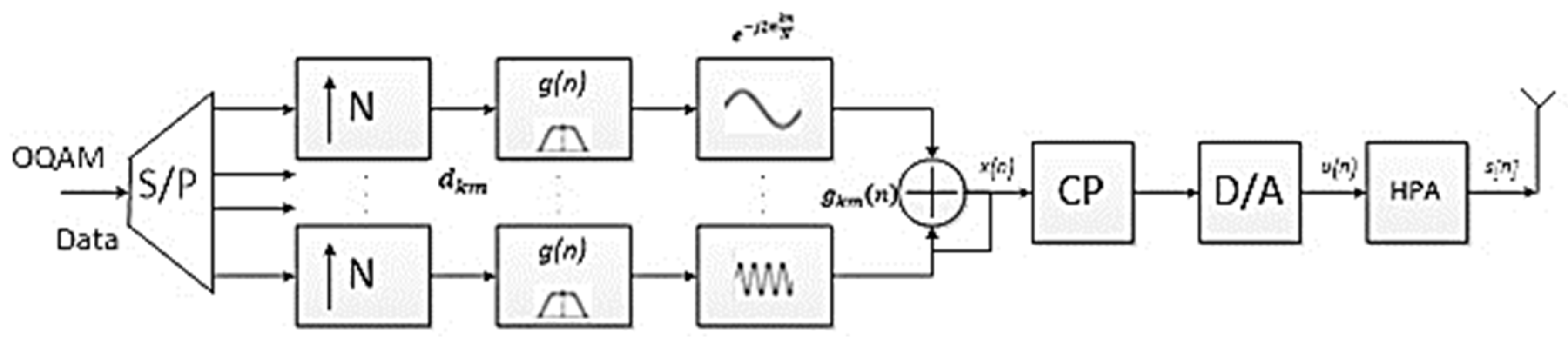
2.1. System Model
2.2. GFDM Predistorter
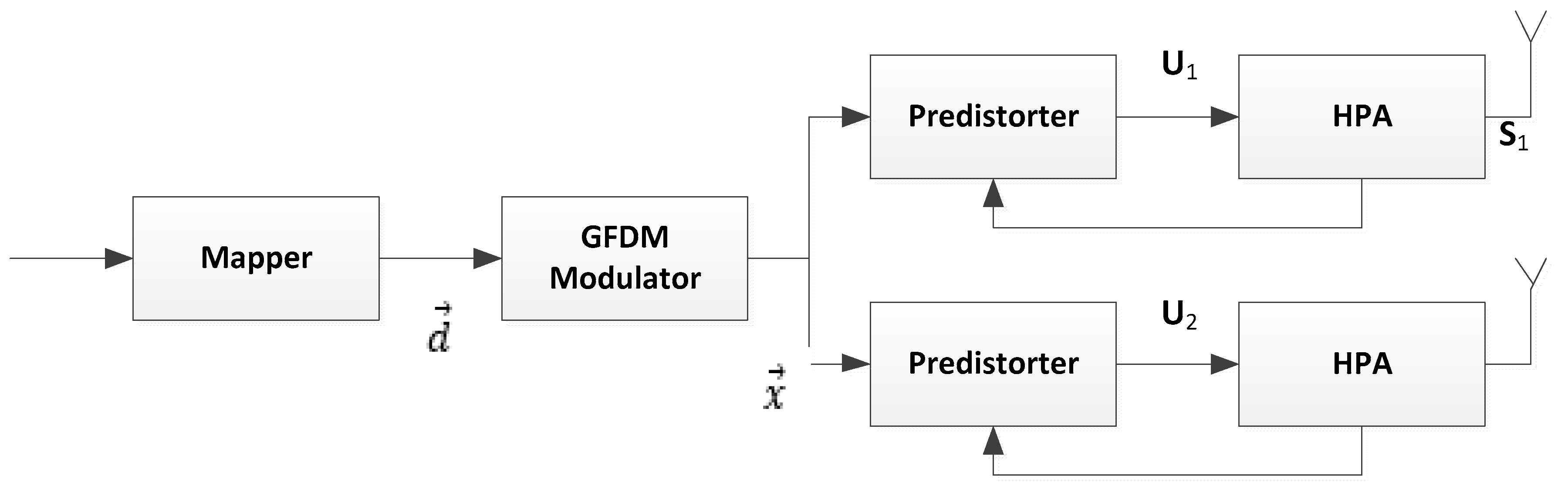
2.3. Proposed Predistorter for MIMO-GFDM Systems
| Algorithm 1 Modelling of Predistorter for MIMO-GFDM Systems | ||
| 1: | d ← b | mapping 16 OQAM |
| 2: | A ← g | pulse shaping RRC |
| 3: | x ← Ad | output GFDM |
| 4: | for k = 1 : K do | per Tx branch |
| 5: | xk(n) ← | input predistorter |
| 6: | rk(n) ← | amplitude predistorter |
| 7: | θk(n) ← | phase of predistorter |
| 8: | uk(n) ← | output predistorter |
| 9: | Rk(n) ← A[rk(n)] | amplitude HPA |
| 10: | phasa HPA | |
| 11: | sk(n) ← | output HPA |
| 12: | end for | |
2.4. HPA Characteristic
2.5. Performance of MIMO-GFDM
3. Results and Discussion
3.1. Predistorter in MIMO-GFDM
3.2. Spectrum Analysis
3.3. PAPR Analysis
3.4. Constellation Diagram
3.5. BER Performance
4. Conclusions
Author Contributions
Funding
Acknowledgments
Conflicts of Interest
References
- Forschung, E.V.; Lucent, A.A.D.; Energie, C.A.L.; Energies, A.U.X. N Instruments. In 5GNOW: Short Name Final Assessment of Demonstrator Concept and Implementation; 5GNOW Project Consortium group: Germany, 2015. [Google Scholar]
- Sharifian, Z.; Omidi, M.J.; Farhang, A.; Saeedi-Sourck, H. Polynomial-based compressing and iterative expanding for PAPR reduction in GFDM. In Proceedings of the ICEE 2015 23rd Iranian Conference on Electrical Engineering, Tehran, Iran, 10–14 May 2015; pp. 518–523. [Google Scholar]
- Fettweis, G.; Krondorf, M.; Bittner, S. GFDM—Generalized frequency division multiplexing. In Proceedings of the IEEE Vehicular Technology Conference, Barcelona, Spain, 26–29 April 2009; pp. 1–4. [Google Scholar]
- Chronopoulos, S.K.; Christofilakis, V.; Tatsis, G.; Kostarakis, P. Preliminary BER Study of a TC-OFDM system operating under noisy conditions. J. Eng. Sci. Technol. Rev. 2016, 9, 13–16. [Google Scholar] [CrossRef]
- Chronopoulos, S.K.; Tatsis, G.; Raptis, V.; Kostarakis, P. Enhanced PAPR in OFDM without Deteriorating BER Performance. Int. Commun. Netw. Syst. Sci. 2011, 4, 164–169. [Google Scholar] [CrossRef]
- Chronopoulos, S.K.; Votis, C.; Tatsis, G.; Kostarakis, P. In depth analysis of noise effects in orthogonal frequency division multiplexing systems, utilising a large number of subcarriers. In Proceedings of the 7th International Conference of the Balkan Physical Union, La Herradura, Spain, 13–17 September 2010; pp. 967–972. [Google Scholar]
- Gumber, K.; Rawat, M. A Modified Hybrid RF Predistorter 5G Linearizer for Ultra Wideband Systems. IEEE J. Emerg. Sel. Top. Circuits Syst. 2017, 7, 547–557. [Google Scholar] [CrossRef]
- Maheswari, G.U.; Govindasamy, A.; Thiruvengadam, S.J. Performance analysis of filter bank multicarrier system with non-linear high power amplifiers for wireless 5G networks. IET Signal Process. 2017, 11, 66–72. [Google Scholar] [CrossRef]
- Varahram, P.; Mohammady, S.; Ali, B.M.; Solomon, N.B. Power Efficiency in Broadband Wireless Communications; CRC Press: Boca Raton, FL, USA, 2015. [Google Scholar]
- Jantunen, P. Modeling of Nonlinear Power Amplifiers for Wireless Communications. Master’s Thesis, Helsinki University of Technology, Espoo, Finland, 2004. [Google Scholar]
- Gregorio, F.H. Analysis and Compensation of Nonlinear Effects of Power Amplifier. Master’s Thesis, Helsinki University of Technology, Espoo, Finland, 2007. [Google Scholar]
- Ortega, A.; Fabbri, L. Performance evaluation of GFDM over nonlinear channels. In Proceedings of the 2016 International Conference on Information and Communication Technology Convergence, ICTC 2016, Jeju, Korea, 19–21 October 2016; pp. 12–17. [Google Scholar]
- Jayati, A.E.; Wirawan; Suryani, T.; Endroyono. Characteristic of HPA Nonlinear Distortion Effects in MIMO GFDM Systems. In Proceedings of the 2018 ICTC, Jeju, Korea, 17–19 October 2018; pp. 379–384. [Google Scholar]
- Cho, L.; Ting, C.H.; Chen, C.Y.; Yau, C.H.; Hsu, C.Y. When UUDN meets 5G waveforms: New challenge of signal linearity? In Proceedings of the 2017 IEEE International Conference on Applied System Innovation: Applied System Innovation for Modern Technology, ICASI 2017, Sapporo, Japan, 13–17 May 2017; pp. 770–773. [Google Scholar]
- Abdelaziz, M.; Anttila, L.; Dikmese, S.; Renfors, M.; Wyglinski, A.M.; Valkama, M. Flexible digital predistortion for future spectrally-agile waveforms and 5G radio systems. In Proceedings of the 2015 IEEE 82nd Vehicular Technology Conference (VTC2015-Fall), Boston, MA, USA, 6–9 September 2015. [Google Scholar]
- Miao, P.; Chen, P. Low-Complexity PAPR Reduction Scheme Combining Multi-Band Hadamard Precoding and Clipping in OFDM-Based Optical Communications. Electronics 2018, 7, 11. [Google Scholar] [CrossRef]
- Matthe, M.; Zhang, D.; Fettweis, G. Iterative Detection using MMSE-PIC-GFDM Demapping for MIMO Systems. In Proceedings of the IEEE European Wireless (EW ‘16), (Ml), Oulu, Finland, 18–20 May 2016; pp. 473–479. [Google Scholar]
- Gharaibeh, K.M. Non Linear Distortion in Wireless Communication Using Matlab. Sl; John Wiley & Sons Ltd.: Hoboken, NJ, USA, 2012. [Google Scholar]
- Falconer, D.; Danilo-Lemoine, F.; Lam, C.T.; Sabbaghian, M. Power backoff reduction for generalized multicarrier waveforms. In Proceedings of the Eur Signal Process Conf., Poznan, Poland, 3–7 September 2007; pp. 693–697. [Google Scholar]
- Bulusu, S.S.K.C.; Shaiek, H.; Roviras, D.; Laetitia, C. PA Linearization of FBMC-OQAM Signals with Overlapped Recursive Error Correcting Predistortion. In Proceedings of the International Symposium on Wireless Communication Systems (ISWCS), Poznan, Poland, 20–23 September 2016; pp. 533–537. [Google Scholar]
- Sendrei, L.; Marchevsky, S. Nonlinear noise estimation and compensation in GFDM based communication systems for cognitive radio networks. In Proceedings of the Radioelektronika (RADIOELEKTRONIKA), 2015 25th International Conference, Pardubice, Czech Republic, 21–22 April 2015; pp. 313–316. [Google Scholar]
- Angelis, C.T.; Chronopoulos, S.K. System Performance of an LTE MIMO Downlink in Various Fading Environments System Performance of an LTE MIMO Downlink. In Proceedings of the Second International ICST Conference, Porto, Portugal, 24–25 March 2011. [Google Scholar]
- Datta, J.; Lin, H.P.; Lin, D.B. A method to implement MIMO-based interference avoidance GFDM using spatial modulation. In Proceedings of the IEEE International Conference on Advanced Technologies for Communications, Ho Chi Minh City, Vietnam, 14–16 October 2015; pp. 572–577. [Google Scholar]
- Zhang, D.; Mendes, L.L.; Matthe, M.; Gaspar, I.S.; Michailow, N.; Fettweis, G. Expectation Propagation for Near-Optimum-GFDM MIMO Detection of Signals. IEEE Trans. Wirel. Commun. 2015, 15, 1045–1062. [Google Scholar] [CrossRef]
- Matthe, M.; Mendes, L.L.; Michailow, N.; Zhang, D.; Fettweis, G. Widely Linear Estimation for Space-Time-Coded GFDM in Low-Latency Applications. IEEE Trans. Commun. 2015, 6, 4501–4509. [Google Scholar] [CrossRef]
- Danneberg, M.; Michailow, N.; Gaspar, I.; Matthe, M.; Zhang, D.; Fettweis, G. Implementation of a 2 by 2 MIMO-GFDM transceiver for robust 5G networks. In Proceedings of the 2015 International Symposium on Wireless Communication Systems (ISWCS), Brussels, Belgium, 25–28 August 2015; pp. 236–240. [Google Scholar]
- Qi, J. Analysis and Compensation of Channel and RF Impairments in MIMO Wireless Communication Systems. Ph.D. Thesis, Université du Québec, Quebec City, QC, Canada, 2011. [Google Scholar]
- Aggarwal, P.; Bohara, V.A. Analytical Characterization of Dual-Band Multi-User MIMO-OFDM System with Nonlinear Transmitter Constraints. IEEE Trans Commun. 2018, 6778, 4536–4549. [Google Scholar] [CrossRef]
- Hesami, S.; Dooley, J.; Ziming, W.; Farrell, R. Digital predistorter in crosstalk compensation of MIMO transmitters. In Proceedings of the 2016 27th Irish Signals and Systems Conference, ISSC 2016, Londonderry, UK, 21–22 June 2016. [Google Scholar]
- Yoffe, I.; Wulich, D. Predistorter for MIMO System with Nonlinear Power Amplifiers. IEEE Trans. Commun 2017, 65, 3288–3301. [Google Scholar]
- Abdelaziz, M.; Anttila, L.; Brihuega, A.; Tufvesson, F.; Valkama, M. Digital predistortion for Hybrid MIMO Transmitters. IEEE J. Sel. Top. Signal Process. 2018, 12, 445–454. [Google Scholar] [CrossRef]
- Saleh, A.A. Frequency-Independent and Frequency-Dependent Nonlinear Models of TWT Amplifiers. IEEE Trans. Commun. 1981, 29, 1715–1720. [Google Scholar] [CrossRef]
- Jayati, A.E.; Wirawan; Suryani, T. Analysis of Non-Linear Distortion Effect Model Based on Saleh in GFDM System. In Proceedings of the IEEE International Conference on Comnetsat, Semarang, Indonesia, 6–7 October 2017; pp. 13–18. [Google Scholar]
- Bandari, S.K. GFDM/OQAM Implementation under Rician Fading Channel. In Proceedings of the Intl. Conference on Advances in Computing, Communications and Informatics (ICACCI), Cebu, Philippines, 27–29 May 2016; pp. 256–260. [Google Scholar]
- Matthe, M.; Michailow, N.; Gaspar, I.; Fettweis, G. Influence of pulse shaping on the bit error rate performance and out-of-band radiation of Generalized Frequency Division Multiplexing. In Proceedings of the 2014 IEEE International Conference on Communications Workshops (ICC), Sydney, NSW, Australia, 10–14 June 2014; pp. 43–48. [Google Scholar]
- Michailow, N.; Krone, S.; Lentmaier, M.; Fettweis, G. Bit Error Rate Performance of Generalized Frequency Division Multiplexing. In Proceedings of the 2012 IEEE Vehicular Technology Conference (VTC Fall), Quebec City, QC, Canada, 3–6 September 2012; pp. 1–5. [Google Scholar]
- Bo, A.; Zhi-xing, Y.; Chang-yong, P.; Tao-tao, Z.; Jian-hua, G. Effects of PAPR Reduction on predistortion HPA. IEEE Trans. Electron. Consum. 2005, 51, 1143–1147. [Google Scholar] [CrossRef]
- Zenobio, D.D. Adaptive linearization of Power Amplifiers in multicarrier Orthogonal Schemes. In Proceedings of the IEEE Wireless Communication System Symposium, Long Island, NY, USA, 27–28 November 1995. [Google Scholar]
- Shammasi, S. Performance of a Predistorter Based on Saleh model of OFDM systems in the HPA nonlinearity. In Proceedings of the 2012 14th International Conference on Advanced Communication Technology (ICACT), PyeongChang, Korea, 19–22 February 2012; pp. 148–152. [Google Scholar]
- Dardari, D.; Tralli, V.; Vaccari, A.A. Theoretical characterization of Nonlinear Distortion Effects in OFDM Systems. IEEE Trans. Commun. 2000, 48, 1755. [Google Scholar] [CrossRef]
- Dakhli, M.C.; Zayani, R.; Belkacem, O.B.; Bouallegue, R. Theoretical analysis and compensation for the joint effects of HPA nonlinearity and RF crosstalk in VBLAST MIMO-OFDM systems over Rayleigh fading channels. Eurasip J. Wirel. Commun. Netw. 2014, 1–15. [Google Scholar] [CrossRef]
- –Baig, S.; Rehman, F. Frequency Domain Channel Equalization Using Circulant Channel Matrix Diagonalization. In Proceedings of the 2005 Pakistan Section Multitopic Conference, Karachi, Pakistan, 24–25 December 2005; pp. 1–5. [Google Scholar]
- Kumar, R.; Malarvizhi, S.; Jayashri, S. Time-Domain Equalization Technique for Intercarrier Interference Suppression. OFDM Syst. Inf. Technol. J. 2008, 7, 149–154. [Google Scholar] [CrossRef][Green Version]


| Parameter | Notation | GFDM |
|---|---|---|
| sampling Frequency | 16 | |
| Subcarrier | K | 8 |
| Symbols per block | M | 15 |
| Samples per symbol | N | 10 |
| Pulse Shaping | g | RRC |
| Roll-of-factor | 0.3 | |
| Alpha_a | 2.1587 | |
| Alpha_phi | 4.0033 | |
| Beta_a | 1.1517 | |
| Beta_phi | 9104 | |
| Mapping | 16 OQAM |
© 2019 by the authors. Licensee MDPI, Basel, Switzerland. This article is an open access article distributed under the terms and conditions of the Creative Commons Attribution (CC BY) license (http://creativecommons.org/licenses/by/4.0/).
Share and Cite
Jayati, A.E.; Wirawan; Suryani, T.; Endroyono. Nonlinear Distortion Cancellation using Predistorter in MIMO-GFDM Systems. Electronics 2019, 8, 620. https://doi.org/10.3390/electronics8060620
Jayati AE, Wirawan, Suryani T, Endroyono. Nonlinear Distortion Cancellation using Predistorter in MIMO-GFDM Systems. Electronics. 2019; 8(6):620. https://doi.org/10.3390/electronics8060620
Chicago/Turabian StyleJayati, Ari Endang, Wirawan, Titiek Suryani, and Endroyono. 2019. "Nonlinear Distortion Cancellation using Predistorter in MIMO-GFDM Systems" Electronics 8, no. 6: 620. https://doi.org/10.3390/electronics8060620
APA StyleJayati, A. E., Wirawan, Suryani, T., & Endroyono. (2019). Nonlinear Distortion Cancellation using Predistorter in MIMO-GFDM Systems. Electronics, 8(6), 620. https://doi.org/10.3390/electronics8060620