Next Article in Journal
Low-Power, Subthreshold Reference Circuits for the Space Environment: Evaluated with γ-rays, X-rays, Protons and Heavy Ions
Next Article in Special Issue
Multisensor RFS Filters for Unknown and Changing Detection Probability
Previous Article in Journal
Bistatic-ISAR Linear Geometry Distortion Alleviation of Space Targets
Previous Article in Special Issue
A Novel Multi-Input Bidirectional LSTM and HMM Based Approach for Target Recognition from Multi-Domain Radar Range Profiles
 
 
Correction published on 31 July 2019, see Electronics 2019, 8(8), 855.
Article

915-MHz Continuous-Wave Doppler Radar Sensor for Detection of Vital Signs

1
Department of Electronic Engineering, Yeungnam University, Gyeongbuk 38541, Korea
2
Department of Robotics Engineering, Yeungnam University, Gyeongbuk 38541, Korea
*
Authors to whom correspondence should be addressed.
Electronics 2019, 8(5), 561; https://doi.org/10.3390/electronics8050561
Submission received: 26 April 2019 / Revised: 15 May 2019 / Accepted: 17 May 2019 / Published: 20 May 2019
(This article belongs to the Special Issue Radar Sensor for Motion Sensing and Automobile)

Abstract

:
A miniaturized continuous-wave Doppler radar sensor operating at 915 MHz to remotely detect both respiration and heart rate (beats per minute) is presented. The proposed radar sensor comprises a front-end module including an implemented complementary metal-oxide semiconductor low-noise amplifier (LNA) and fractal-slot patch antennas, whose area was reduced by 15.2%. The two-stage inverter-based LNA was designed with an interstage capacitor and a feedback resistor to acquire ultrawide bandwidth. Two operating frequencies, 915 MHz and 2.45 GHz, were analyzed with regard to path loss for efficient operation because frequency affects detection sensitivity, reflected signal power from the human body, and measurement distance in a far-field condition. Path-loss calculation based on the simplified layer model indicates that the reflected power of the 915 MHz radar could be higher than that of the 2.45 GHz radar. The implemented radar front-end module excluding the LNA occupies 35 × 55 mm2. Vital signs were obtained via a fast Fourier transform and digital filtering using raw signals. In an experiment with six subjects, the respiration and heart rate obtained at 0.8 m using the proposed radar sensor exhibited mean accuracies of 99.4% and 97.6% with respect to commercialized reference sensors, respectively.

1. Introduction

Radar technology can detect vital signs such as respiration and heart rate without contact electrodes [1]. Among various noncontact vital-sign detectors, the radar sensor has advantages for various industrial applications, such as driver-status monitoring, human-motion recognition, passenger detection systems, and smart home appliances, owing to its operating principle of not infringing on privacy and the difficulty of detecting sensor operation [1,2,3]. A continuous-wave (CW) radar, which transmits and receives continuous signals and measure vital signs according to changes between transmitted and received signals, can be implemented using simple front-end configuration with a single operating frequency in a narrow bandwidth and can easily remove stationary clutter [4,5,6,7].
The CW radar for detecting vital signs has exhibited high sensitivity to small displacements with frequency bands of ≥2 GHz because more signal changes can be detected at a higher operating frequency [1,2,3]. A radar sensor operating at a higher frequency also has the advantage of miniaturization, because operating frequency determines the size of the radar module, particularly the size of the antennas [4,5,6]. However, high-frequency signals have difficulty penetrating the inside of the human body, and attenuation loss can be significantly increased when electromagnetic (EM) waves are transmitted through high-dielectric materials, such as muscles and skin [8]. It was previously reported that the signal reflected by the heart is only 4% of the incident signal for a 2.45 GHz CW radar [9]. Even though most of the received signals for a radar sensor operating in the S-band (2 GHz to 4 GHz) or higher are reflected by the chest surface, the radar sensor can detect vital signs because the displacements of heartbeat and respiration are 0.6 and 4−12 mm, respectively [10]. Highly accurate vital signs can be measured using signals reflected from deep inside of the human body, which reflect more information of the characteristics of the heartbeat and respiration, because these displacements are dependent on individual body characteristics and conditions, such as physiology, health, fitness, and age [9,10].
There are two main methods for increasing the accuracy of vital-sign detection from the increase of the human body’s transmittance: the use of a low operating frequency and the increase of transmitted power [11]. The impulse radar sensor corresponds to the latter method because it transmits high output power at a certain time, even though output power in the frequency band is kept low [12,13]. Because output power from a radar sensor generally ranges from −10 dBm to 10 dBm, which is lower than the harmful level of EM waves to the human body, output power may be further increased to obtain the high transmittance of the body [14,15]. However, increasing output power is not preferable because it can cause a physiological hazard to the subject, even if EM waves below the specific level cannot affect the human body [15]. Reducing operating frequency can increase penetration depth in the human body, but can reduce sensitivity when the sensor operates in a near-field condition [16]. Whether the sensor operates in near- or in far-field condition is determined by comparing the measured distance and the Fraunhofer distance, calculated using effective sizes of the antenna and target depending on operating frequency [17]. Therefore, operating frequency is an important factor affecting the performance of the CW Doppler radar sensor for vital-sign detection.
This paper introduces a 915 MHz CW Doppler radar sensor comprising an ultra-wideband low-noise amplifier (LNA) and fractal-slot patch antennas to obtain heart rate and respiration. A fractal-slot patch antenna and an inverter-based complementary metal-oxide semiconductor (CMOS) LNA with an inter-stage capacitor and a feedback resistor were designed to achieve high compactness and the wideband characteristic of a radar front-end module. Path losses of 915 MHz and 2.45 GHz CW signals traveling into the human body were calculated to examine the effect of the operating frequency. The radar sensor operating in the 915 MHz industrial, scientific, and medical radio band can have high accuracy for detecting vital-sign information due to high penetration and low signal loss in the human body. The remainder of the paper is organized as follows. Section 2 present a block diagram and the operating principle of the radar, as well as calculation results. Implementation, including the fractal-slot patch antenna and the integrated LNA for obtaining impedance matching with the antenna and improving sensitivity, is described in Section 3. Section 4 describes the experimental environment and presents the measurement results for respiration and heart rate, obtained using the proposed radar sensor. The performance of the radar sensor is analyzed and compared with that of a commercial electrocardiogram (ECG) sensor in Section 4. Conclusions are drawn in Section 5.

2. 915 MHz CW Doppler Radar Sensor

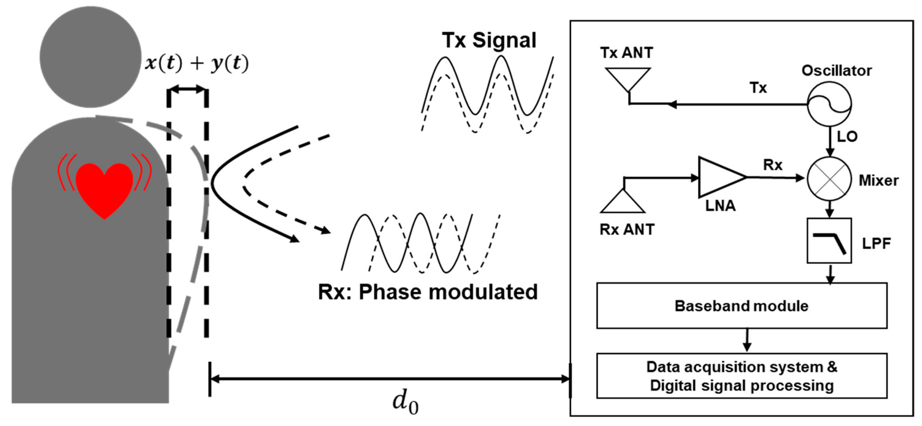
2.1. Radar Architecture

Figure 1 shows a block diagram of the detection of vital signs using a CW Doppler radar sensor. Transmitted signal T(t), generated by the free-running oscillator, is expressed as
T ( t ) = A t cos ( 2 π f 0 t + φ ( t ) ) ,
where At represents the magnitude of the transmitted signal, f0 represents the operating frequency of the radar sensor, t represents time, and φ ( t ) represents the phase noise of the oscillator. Because of the Doppler shift generated by the respiration and heartbeat of the subject, received signal R(t) can be expressed as a phase-modulated signal, as follows:
R ( t ) = A r cos ( 2 π f 0 t 4 π λ ( d 0 + x ( t ) + y ( t ) ) + φ ( t 2 d 0 c ) ) ,
where Ar represents the magnitude of the received signal, d0 represents the distance from sensor to subject, λ represents wavelength corresponding to operating frequency, c represents the velocity of the EM waves in free space, and x(t) and y(t) represent the time-varying displacements caused by respiration and heartbeat, respectively; x(t) and y(t), due to vital signs, are significantly smaller than the wavelength corresponding to the operating frequency. The received signal and the local oscillator (LO) signal, coupled with the transmitted signal, are downconverted by a frequency mixer and a low-pass filter into the baseband signal, as follows:
B ( t ) = A B cos ( θ + 4 π λ ( x ( t ) + y ( t ) ) + Δ φ ) ,
where AB represents the magnitude of the baseband signal. Phase variation θ over the distance from sensor to subject is given as 4πd0/λ, and residual phase noise Δφ is given by φ ( t ) φ ( t 2 d 0 c ) . It is assumed that residual phase noise can be neglected when the LO and received signals are generated by the same oscillator due to the range correlation effect [18]. If θ is an odd multiple of π/2, baseband signal B(t) can be represented with small-angle approximation of the sine function, as follows:
B ( t ) = A B sin ( 4 π λ ( x ( t ) + y ( t ) ) ) 4 π A B λ ( x ( t ) + y ( t ) ) .
When θ approaches an even multiple of π/2, it is difficult to distinguish vital signs at the baseband output of the radar sensor due to the null-point problem [19]. A radar sensor with a single output channel has limited operation owing to distance dependence, but this problem can be solved by using a quadrature receiver or the demodulation method [18,20]. For a 915 MHz radar sensor with a single output channel, the null-point problem can be avoided by adjusting the distance from the sensor to the subject and implementing a simple hardware configuration.

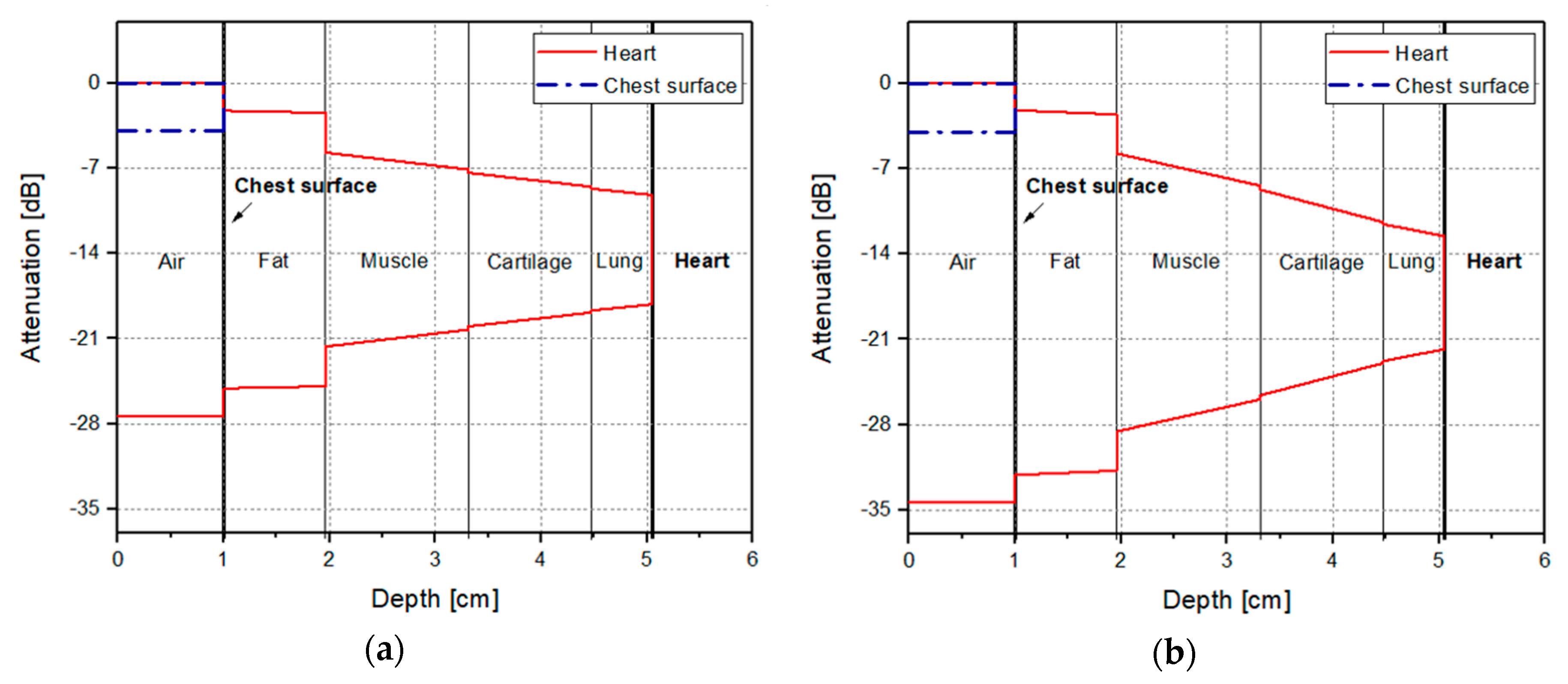
2.2. Path-Loss Calculation

In the human body, the region from the skin to the heart, which is a measurement target of the radar sensor, has a multilayer structure with various dielectric properties. These properties vary with respect to EM wave frequency, and depend on personal characteristics, such as age, gender, and race [7]. The layer constituting the inside of the human body was defined according to biological information obtained from a well-examined male cadaver [9,21,22]. Based on previous studies, the EM properties of human-body tissue at 915 MHz and 2.45 GHz were calculated, as presented in Table 1 and Table 2, respectively [21,23,24]. Properties are shown only for human-body layers in the region from the radar sensor to the heart, which is the main observation target. Properties related to energy loss of EM waves in each layer differed according to frequency, whereas other properties did not show significant differences. Calculation results showed that conductivity and attenuation at 915 MHz were lower than those at 2.45 GHz. These results agree with the well-known fact that. at the same transmitted power, EM waves can more deeply penetrate inside the body when operating frequency is reduced.
Calculation results for path loss in human-body layers are shown in Figure 2, indicating the received power level that can be obtained from the radar sensor operating at 915 MHz and 2.45 GHz in each layer. Permeability was assumed to be 1 in all types of tissue, and multiple reflections in each layer were neglected in the calculation. For the same output power of 0 dBm, signal attenuation at the chest surface was calculated to be approximately equal to −3.9 dB and −4 dB at 915 MHz and 2.45 GHz, respectively. Signal levels reflected by the heart were calculated to be −27.35 dB at 915 MHz and −34.33 dB at 2.45 GHz. It is considered that the signal received by the radar sensor operating at 915 MHz contained more information regarding the movement of the heart, because the signal reflected by the heart is 7 dB higher. The attenuation level given by path-loss calculation may vary depending on human-body characteristics or human-body layer modeling. However, calculations clearly indicate the tendency of path-loss reduction for EM waves with the reduction of the frequency. The same tendency of EM waves passing through the human body was reported for different frequency bands [24].

3. Implementation of Radar Sensor

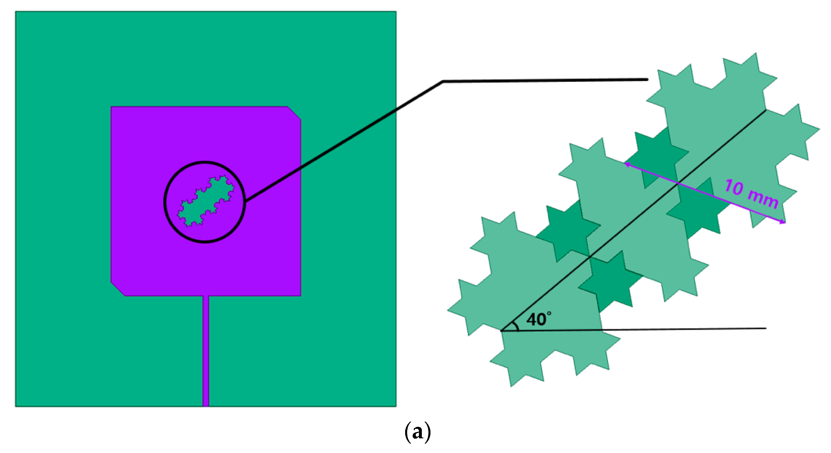
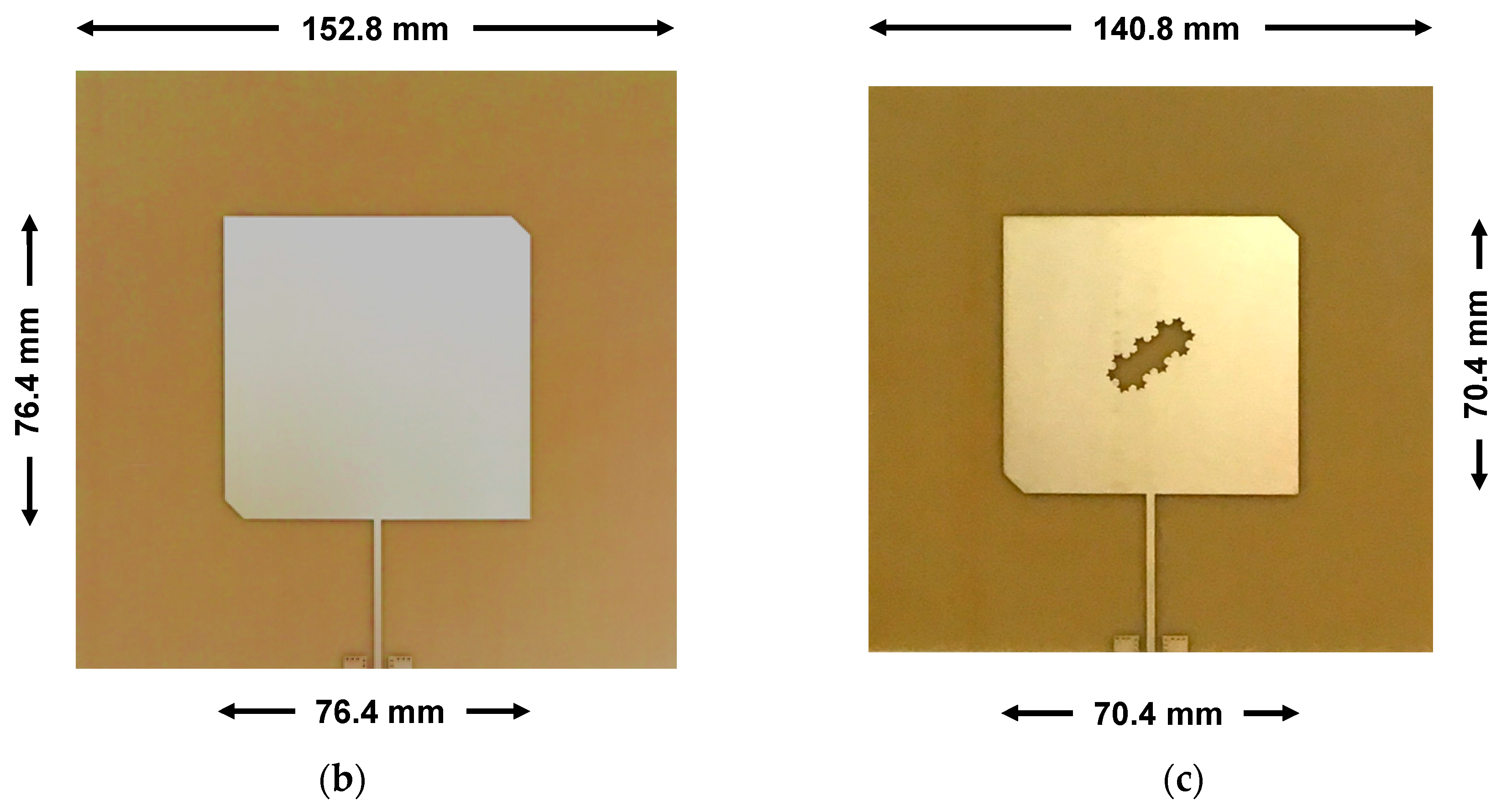
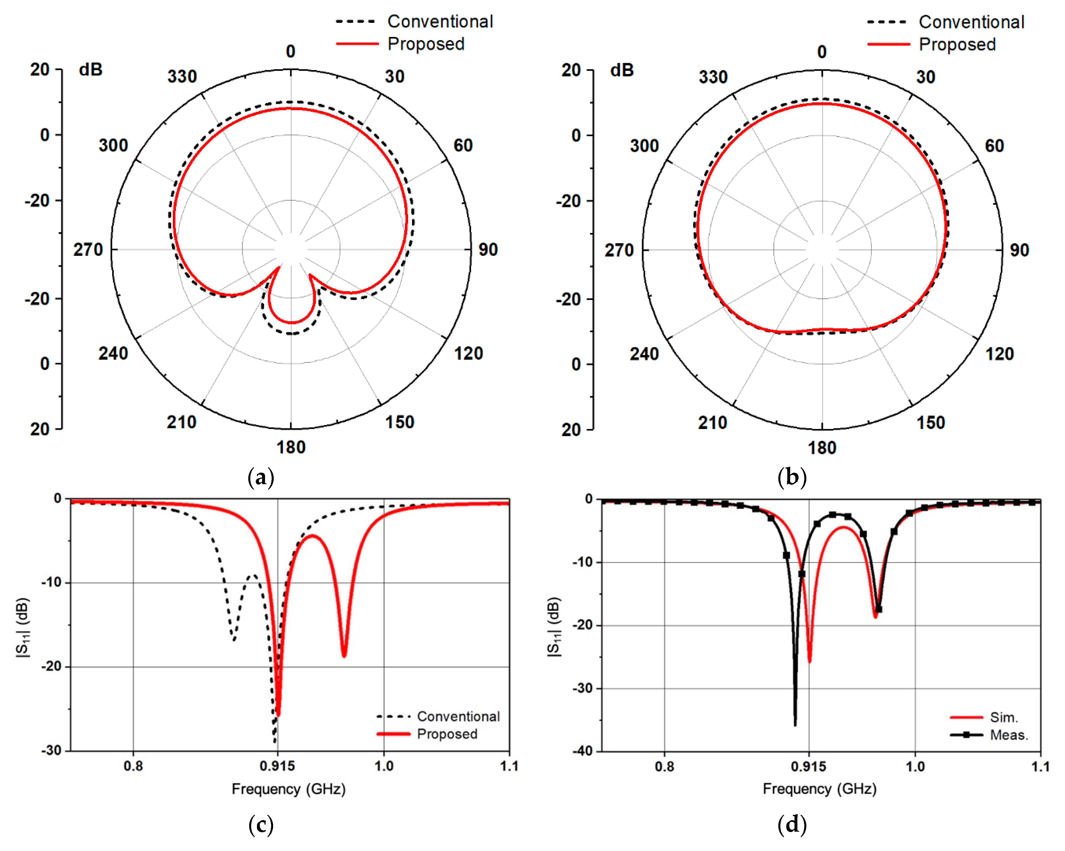
3.1. Fractal-Slot Patch Antenna
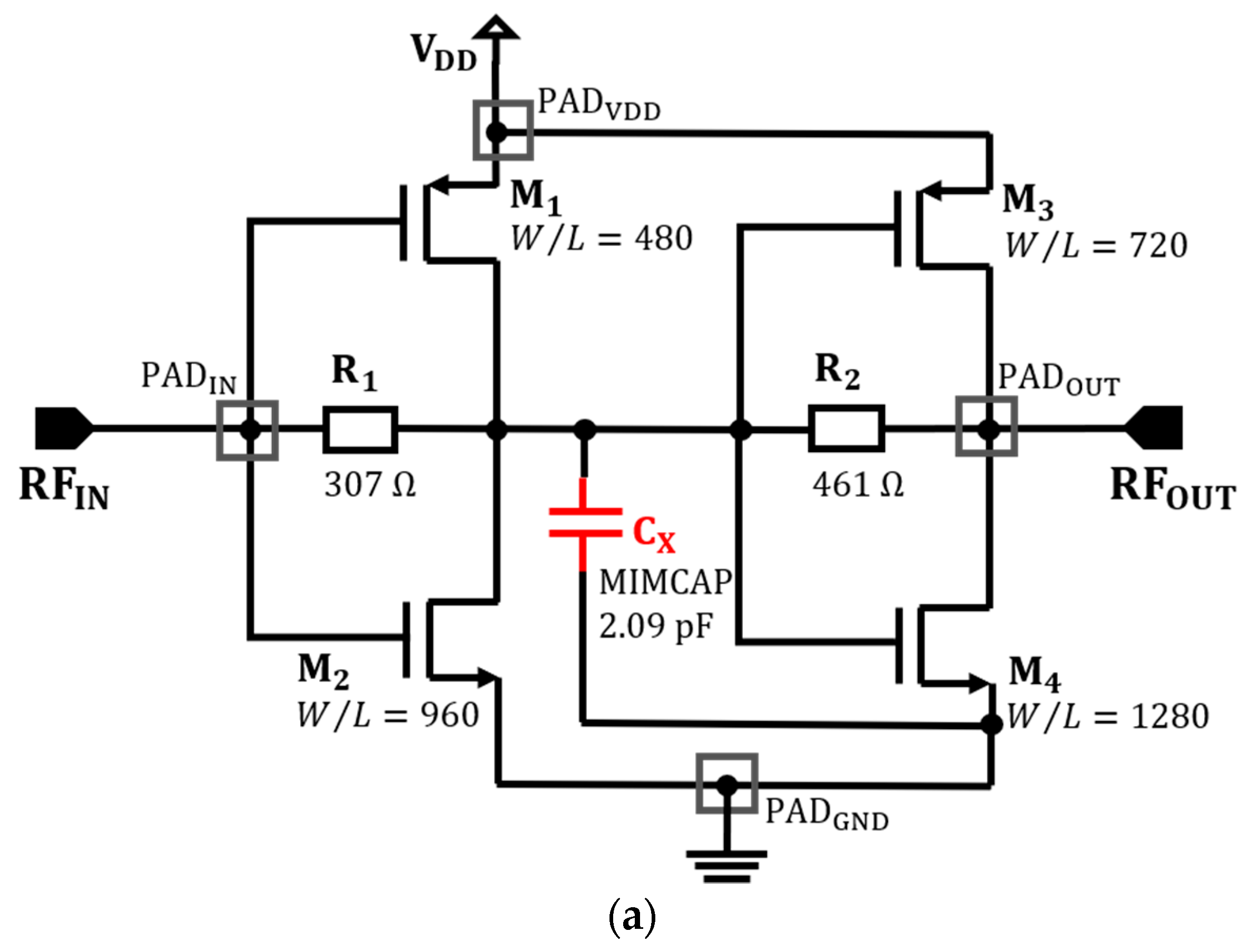
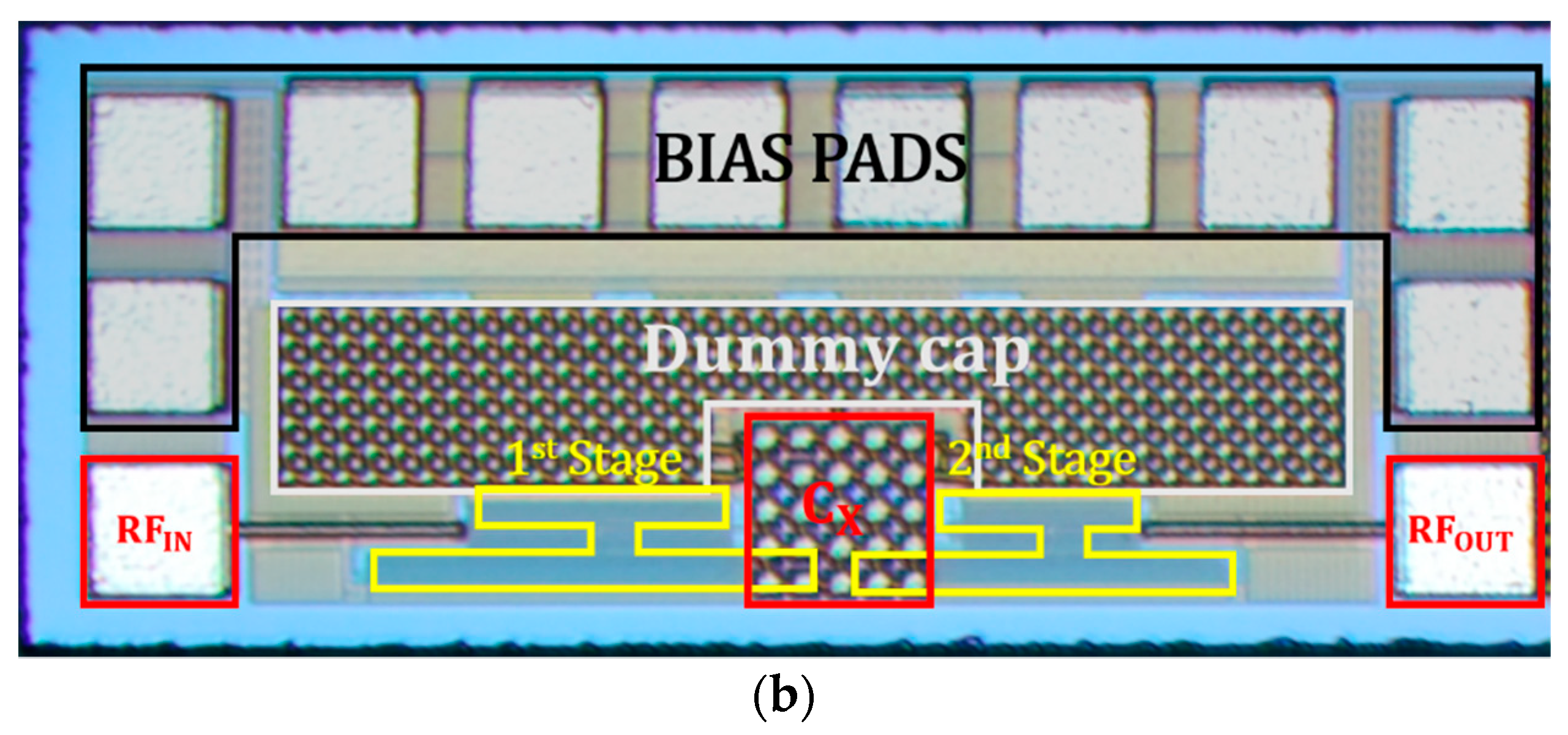
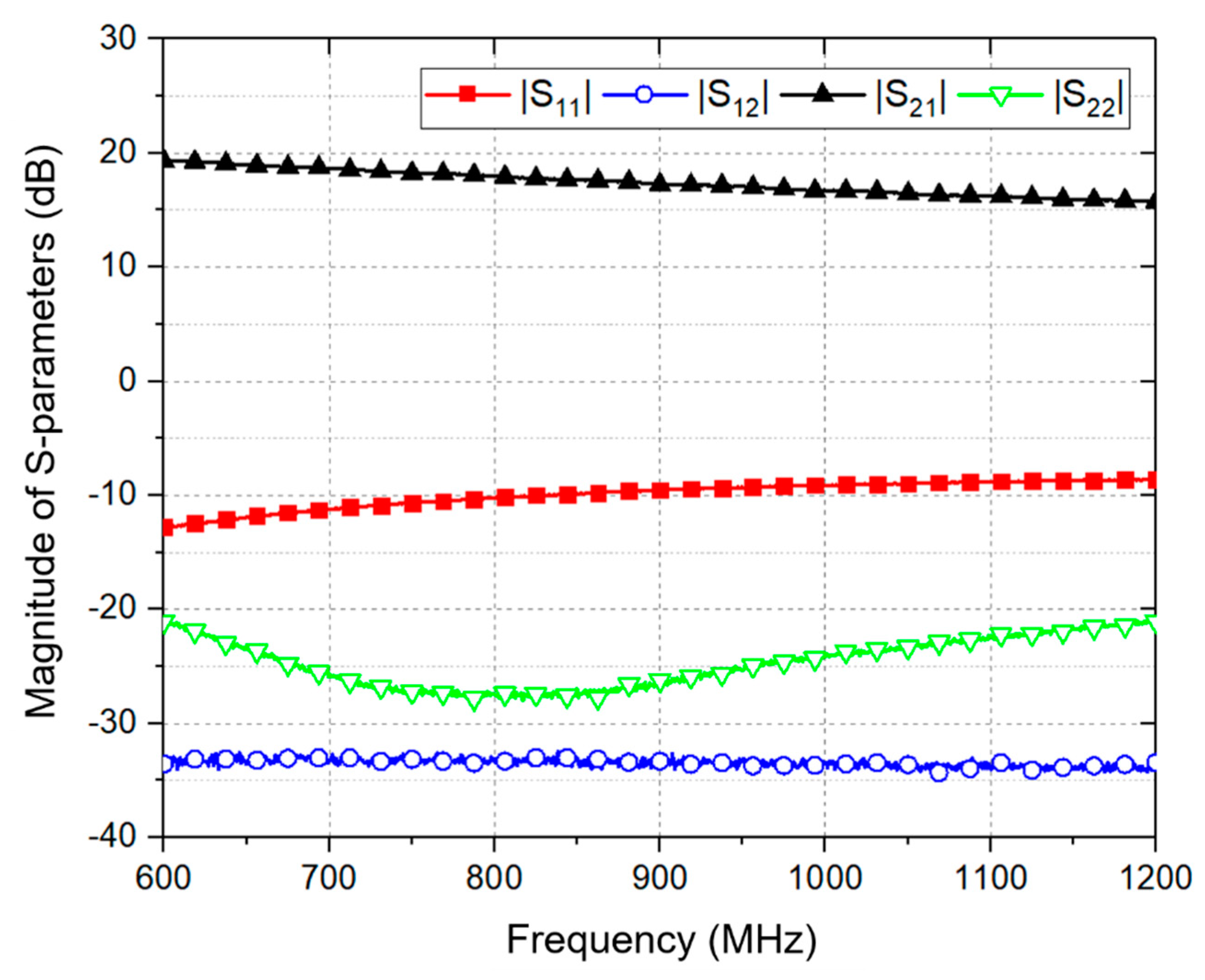
The reduction of antenna size is required for miniaturizing the 915 MHz radar sensor for vital-sign detection, because antenna size is proportional to the wavelength of the operating signal. There are small surface-mounted-device-type products fabricated on high-permittivity ceramic substrates that operate in the frequency band below 1 GHz, but conventional linearly polarized antennas have a limit in detecting various movements related to respiration and the heart. A patch antenna for a 915 MHz radar sensor on an FR4 substrate was designed via the size-reduction method using a fractal slot because of the easy design and fabrication of the desired characteristics [25]. Circular polarization was implemented in the proposed antenna with a truncated edge at the diagonal patch. Antenna size can be reduced by designing the resonance frequency with an arbitrary shape inside the patch because the operating frequency of the antenna is inversely proportional to the effective path length of the EM wave [26]. However, as patch size decreases owing to the implementation of the arbitrary shape, the radiation efficiency of the antenna decreases [27]. A fractal-slot patch antenna that can increase path length with a small pattern is advantageous for implementing a miniaturized antenna while maintaining antenna performance [28]. The proposed fractal slot is inserted in the center of the patch antenna with three Koch snowflake patterns, as shown in Figure 3, for increasing the surface current path on the patch. The ANSYS HFSS 3D EM simulator was used to design the shape with optimal parameters to obtain a long resonance wavelength for the patch. The optimized shape from the simulation was tilted by 40°, which is similar to the truncated angle of the patch (45°). The proposed antenna with a fractal slot on an FR4 substrate with a permittivity of 4.4 and a thickness of 1 mm has a patch length of 70.4 mm, which is 6 mm (7.9%) smaller than that of a conventional patch antenna. Physical size was also reduced by 15.2% compared with a conventional patch antenna with the same operating frequency. As shown in Figure 4, the proposed antenna was simulated to have a return loss of 26 dB at 915 MHz, a −10 dB bandwidth of 17 MHz (from 907 MHz to 924 MHz), a half-power beam width of 108°, and a radiation efficiency of 12%. The simulated performances and radiation patterns were similar to those of a conventional antenna despite size reduction. The antenna gain of the proposed antenna was −5.8 dB, which is smaller than that of a conventional antenna of −4.1 dB because of the decrease of radiation efficiency in the proposed antenna. The maximum return loss of the antenna was measured at 905 MHz and was downshifted by 10 MHz from the desired frequency owing to the fabrication tolerance of the printed circuit board (PCB).

3.2. Two-Stage LNA

The proposed design can reduce the size of the patch antenna in the 915 MHz band, but measured return loss was 6 dB at the desired center frequency of 915 MHz. Because the low return loss can degrade signal sensitivity, the proposed radar sensor was implemented with an LNA connected to the antenna for impedance matching. The wideband LNA shown in Figure 5 is proposed to improve the sensitivity of the radar sensor and impedance matching with the antenna. The proposed LNA is a two-stage inverter-based amplifier with resistive feedback. Inverter-type LNA achieves wideband input- and output-impedance matching using feedback resistors, according to the size of the n- and p-type metal-oxide semiconductor transistors [29]. However, impedance mismatching may be generated to obtain the desired voltage gain in the inverter-based LNA, because the transconductances and output resistances of the transistors affect the wideband input and output matching characteristics and the voltage gain. Impedance mismatch can be compensated by adding capacitance Cx, shown in Figure 5a, between the first and second stages in the proposed LNA. Additional capacitance Cx can not only increase the degree of freedom in the inverter-based LNA design without increasing the noise figure but also be useful for achieving impedance matching with the proposed fractal-slot antenna. Capacitance characteristics at the input of the LNA can be designed to compensate for the inductance characteristics of the antenna, because the input capacitance of the first stage, which depends on the size of the transistors, can be adjusted by changing capacitance Cx.
The proposed LNA was fabricated using TSMC (Taiwan Semiconductor Manufacturing Company) 0.25 μm mixed-signal CMOS process technology with one polylayer and five metal layers, as shown in Figure 5b. The chip area of the LNA is 0.23 mm2, and external bond-wire inductors and discrete capacitors were used for input and output matching. Simulation results show that the LNA obtains both a voltage gain of ≥20 dB, and wideband input and output matching via interstage capacitance Cx. As indicated by the simulated results in Table 3, at 915 MHz, input and output matching were improved by the capacitance Cx without any significant effect on the noise figure and the voltage gain of the LNA. Input P1dB was simulated to be −15.7 dBm; thus, it can be predicted that the linearity of the LNA would not affect the operation of the radar sensor compared with the received power based on path-loss calculation.
Figure 6 shows the magnitudes of the measured S-parameters of the proposed LNA. Degradation in the measured voltage gain and input matching was caused by the difference in bond-wire inductance between simulation and implementation. The magnitude of the input reflection coefficient was degraded; however, the Smith chart in Figure 7 shows that impedance ZANT of the antenna was matched with input impedance ZLNA of the LNA using a radiofrequency cable with a characteristic impedance of 50 Ω and a length lcable of 200 mm. The return loss of the antenna connected to the LNA was calculated to be 12.8 dB.

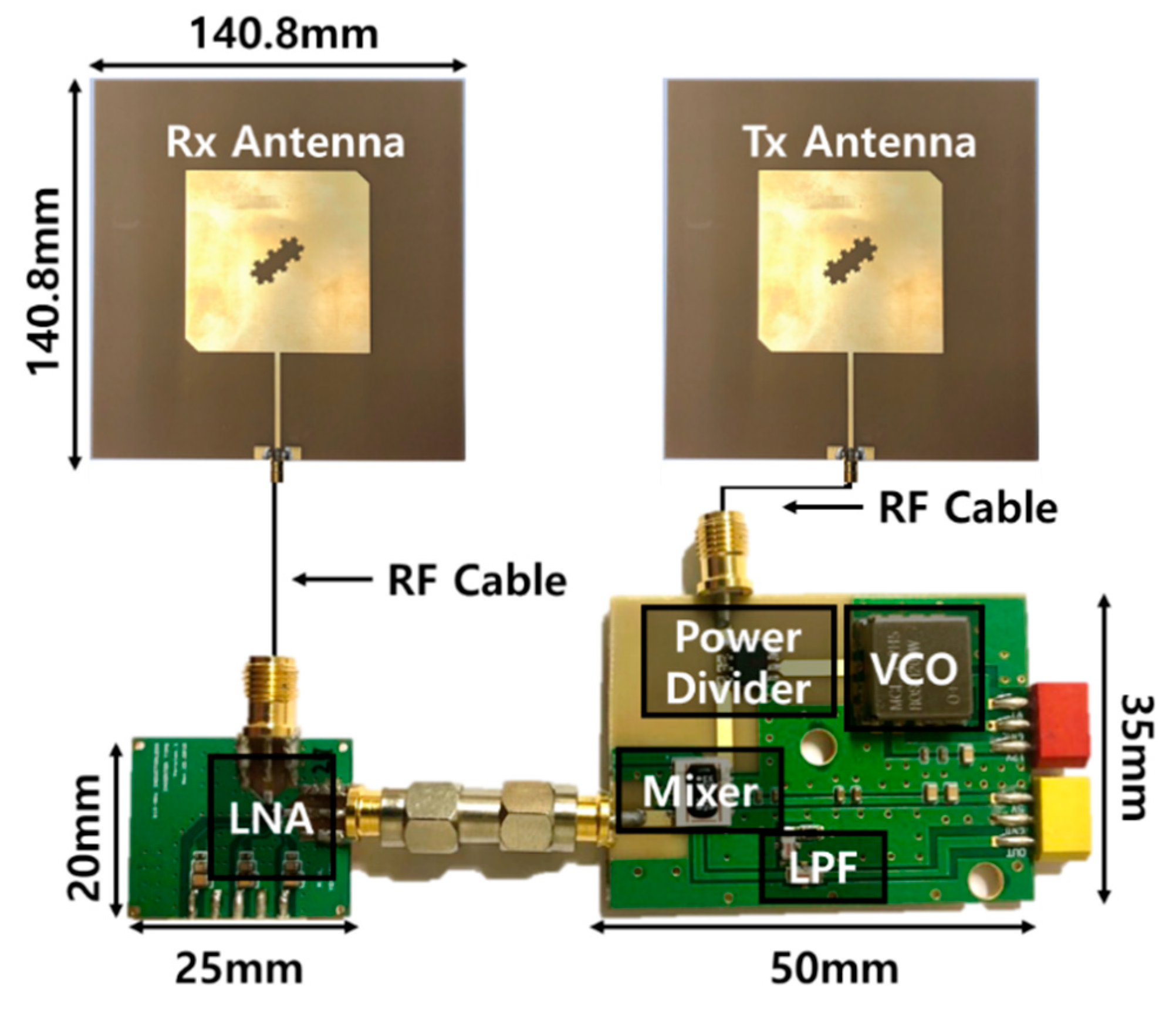
3.3. 915 MHz Radar Sensor Module

The front-end module of the 915 MHz CW radar sensor shown in Figure 8 was implemented on an FR4 PCB with a thickness of 1 mm. Signals of 915 MHz with an output power of 9 dBm were generated at the voltage-controlled oscillator (VCO) and divided into LO and Tx paths by a power divider with an insertion loss of 0.4 dB. The maximum output power of the transmitted signal was less than 3 dBm because of the input return loss of the proposed antenna and the intrinsic loss of the connectors. Additionally, the reflected signal was received by the proposed antenna and amplified using the chip-on-board LNA with a voltage gain of 17 dB at 915 MHz. The received signal was downconverted to the baseband signal by a passive mixer with a conversion gain of −7.54 dB and a low-pass filter with a cutoff frequency of 80 MHz. The board size of the front-end module is 50 × 35 mm.

4. Measurements and Discussion

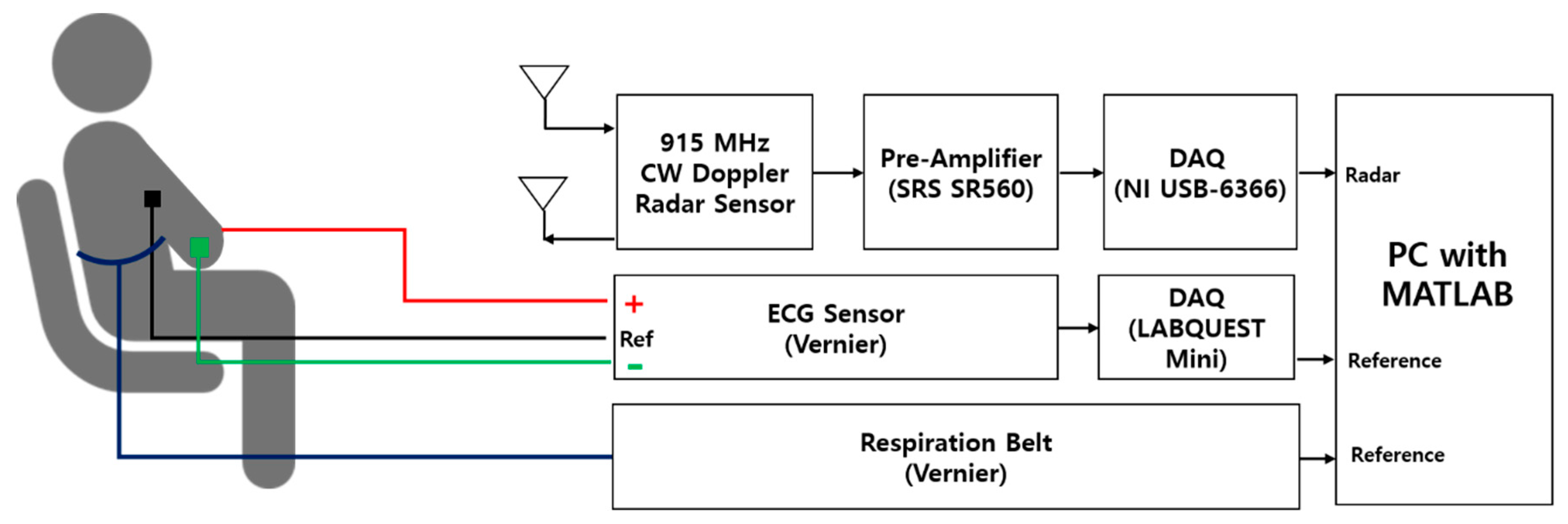
4.1. Experiment Setup

Vital signs, particularly heart rate, obtained from the 915 MHz radar sensor are compared with the output of the reference sensors to evaluate the accuracy of the proposed radar sensor. Figure 9 shows the measurement setup for vital-sign detection using the proposed 915 MHz radar sensor module. Vital signs of a subject at a distance of 80 cm from the module were measured by using the three sensors for 30 seconds. The signal-to-noise ratio of the vital signals measured by the 915 MHz radar sensor at a distance of 80 cm could decrease under a near-field condition compared with a far-field condition [16]. However, because the power of the signal received by the sensor decreases as distance increases, the subject was positioned at a distance of 80 cm, which is proper for detecting vital signs of the human body with consideration of the operating conditions of the sensor. The raw data from the radar module were conditioned using a SR560 preamplifier (Stanford Research Systems), with a voltage gain of 27 dB and a passband from 0.03 Hz to 0.3 Hz to satisfy the input range of the data-acquisition (DAQ) board (National Instruments). The data sampled at 1000 samples per second were transformed into the frequency domain by using a fast Fourier transform (FFT) in MATLAB. The reference sensor (EKG-BTA, Vernier Software and Technology) obtains ECG signals using three electrodes and another DAQ board, and the heart rate, sampled at 200 samples per second, was displayed in MATLAB. Reference respiration was measured with a piezoelectric-based belt-type sensor manufactured by Vernier Software and Technology, sampled at 20 samples per second and displayed in MATLAB. Experiments were carried out on six subjects composed of five male and one female subjects in their 20s. Each experiment was conducted once for each subject. The accuracy of the radar sensor was demonstrated by comparing respiration and heart rate (beats per minute, BPM) obtained from the radar sensor with those obtained from the reference sensors.

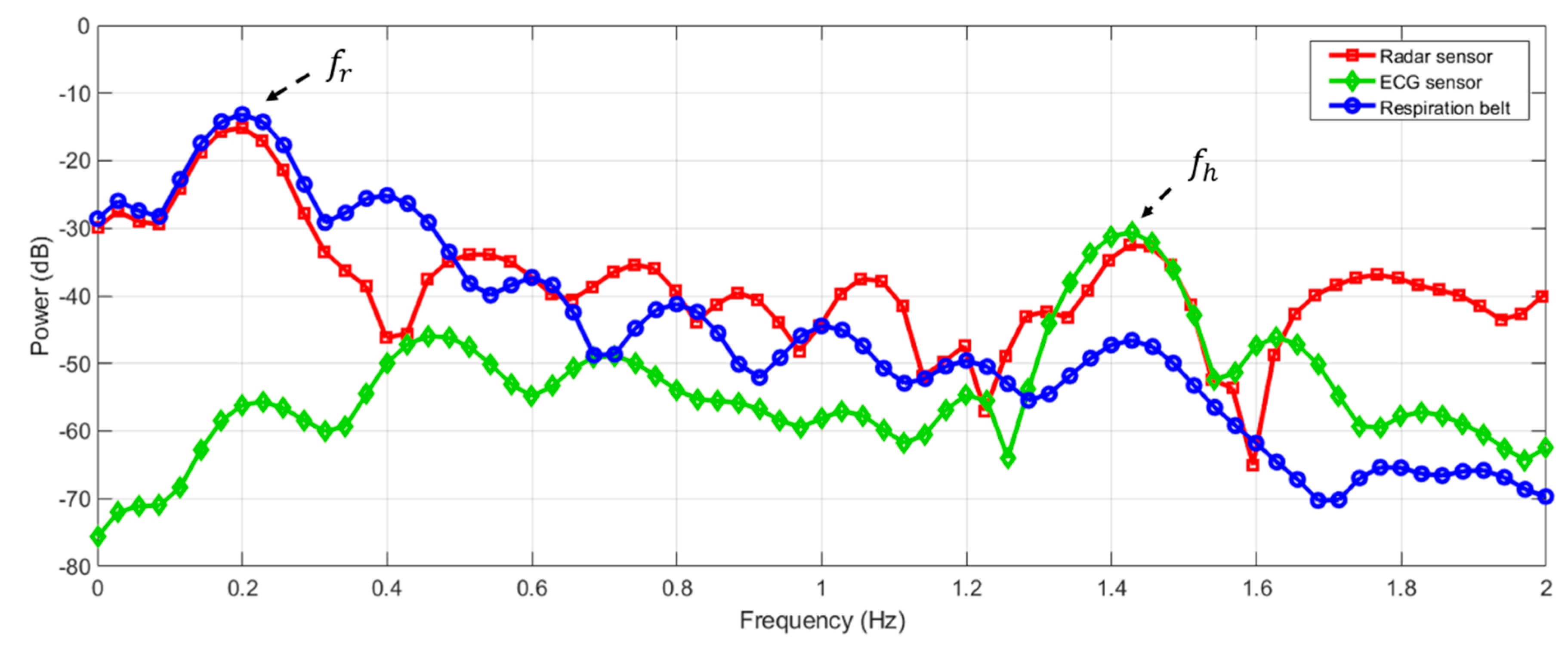
4.2. Measurement Results and Discussion

Respiration and heart rate are calculated by extrapolating the peak values obtained by taking the FFT of the data measured for 10 to 60 seconds [10]. Figure 10 shows the frequency-domain spectra of vital signs measured by the proposed radar sensor and the ECG sensor for 30 seconds. The vital signs obtained from the radar sensor clearly show frequency peaks fr and fh, corresponding to respiration and heartbeat, respectively. Frequencies fr for respiration and fh for heartbeat obtained from the radar sensor were observed at similar frequencies to those obtained from the ECG sensor and those obtained from the respiration belt, respectively. The ECG sensor could obtain a highly accurate heart rate because it directly monitors electrical signals generated by the heartbeat. The respiration belt could accurately detect respiration rate because breathing can be observed from the movement of the chest cavity. The measured signals of the radar sensor exhibited a higher noise level than those of the reference sensors even though raw data in the radar sensor are filtered in the desired frequency band by the preamplifier. The operating principle of the radar sensor, which monitors the physical-movement change caused by the heartbeat, is one of the reasons why the noise level of the radar sensor is higher than that of the ECG sensor.
In the case of the radar sensor without the proposed LNA, measurement accuracy of the heart rate was reduced owing to the input return loss of the proposed antenna and the decrease in signal sensitivity. Table 4 presents the measured heart rates and error rates with and without the proposed LNA in the radar sensor.
Table 5 shows that the measurement accuracy of the proposed radar sensor depends on the distance of the subject. The detection errors of the vital signs using the proposed radar sensor for one subject were measured to be less than 3% at a distance of 40 cm to 100 cm. Measurement results show that the setup distance of 80 cm was within the range that can obtain stable BPM, although it is not an optimal distance to detect the vital signs of a subject.
Comparing with the reference sensors, the measured respiratory and heart rates for six subjects are shown in Table 6. The measured respiration for the proposed radar sensor had an error rate of <0.6% compared with that measured using the respiration belt-type sensor. There was almost no deviation depending on the subjects in the measurement results of the respiration. Results show that the radar sensor could obtain enough signal-to-noise ratio because motion by respiration can be largely detected from the surface of the human body for a stationary subject. Measurements of the heart rate showed a mean error of 2.4% compared with measurements using the ECG sensor, but there was significant difference between the smallest error of 0.21% and the largest error of 4.89%. It is shown that detection accuracy of the heart rate using the proposed radar sensor could vary depending on the subjects due to the requirement of high sensitivity of heart-rate detection even with the high penetration of the transmitted signal in the proposed radar sensor.
In the CW Doppler radar sensor, the magnitude of the phase-modulated signal caused by the motion of respiration and the heartbeat is represented by the motion multiplied by 4π/λ, as shown in Section 2. A wavelength of approximately 30 cm may cause the 915 MHz radar sensor to have a low sensitivity to the motion generated by respiration and heartbeat (a few millimeters) at the surface of the human body. Nevertheless, it was demonstrated that the proposed radar sensor can achieve highly accurate vital-sign detection because the power of the received signal and the effects of the movement of the internal organs can be increased by the low path loss inside the human body. The effect of body movement could not be eliminated in the proposed radar sensor, even with low operating frequency. Multichannel Doppler radar sensors, which simultaneously detect vital signs from several radar sensors with various operating frequencies located at different positions, including the proposed radar sensor, may be an effective approach for moving-body cancellation of vital-signal detection with the radar sensor.

5. Conclusions

A CW Doppler radar-sensor module operating at 915 MHz was proposed for detecting respiration and heartbeat. The proposed radar sensor is insensitive to surface movements caused by respiration and heartbeat due to its operating frequency of 915 MHz. However, path-loss calculation at 915 MHz and 2.45 GHz indicates that the received power of the radar sensor, which includes movement inside the human body, is higher than that of another radar sensor operating at a higher frequency. A circularly polarized fractal-slot patch antenna design was proposed to reduce antenna size, and patch area was reduced by 15% compared with a conventional patch antenna operating at 915 MHz. An LNA-integrated circuit was employed for impedance matching with the proposed antenna and sensitivity improvement. The proposed amplifier is an inverter-based two-stage amplifier with resistive feedback and interstage capacitors for obtaining wideband input and output matching and high voltage gain. The respiration and heartbeat signals measured using the proposed radar sensor were clearly distinguishable from each other. The mean error rates of respiration and heart rate measured by the radar sensor, including the antenna and LNA, were 0.3% and 2.4% compared with those measured by commercial piezoelectric and ECG sensors, respectively.

Author Contributions

Conceptualization, J.-H.P. and J.-R.Y.; methodology, J.-H.P. and J.-R.Y.; software, J.-H.P.; validation, J.-H.P., Y.-J.J., G.-E.L., and J.-R.Y.; formal analysis, J.-H.P. and J.-R.Y.; investigation, J.-H.P., J.-T.O., and J.-R.Y.; resources, J.-R.Y.; data curation, J.-H.P.; writing—original-draft preparation, J.-H.P., Y.-J.J., G.-E.L., J.-T.O., and J.-R.Y.; writing—review and editing, J.-H.P., J.-T.O., and J.-R.Y.; visualization, J.-H.P. and J.-T.O.; supervision, J.-R.Y.; project administration, J.-R.Y.; funding acquisition, J.-T.O. and J.-R.Y.

Funding

This research was funded by the 2018 Yeungnam University Research Grant (No. 218A580061). And It was also supported by the National Research Foundation of Korea (NRF), grant funded by the Korean government (MSIT) (No. 2019R1G1A1003865).

Acknowledgments

The authors thank Jae-Yong Shim for supporting the experiment involving the radar sensor.

Conflicts of Interest

The authors declare no conflict of interest.

References

  1. Chen, K.M.; Huang, Y.; Zhang, J. Microwave life-detection systems for searching human subjects under earthquake rubble or behind barier. IEEE Trans. Biomed. Eng. 2000, 47, 105–114. [Google Scholar] [CrossRef] [PubMed]
  2. Lin, F.; Zhuang, Y.; Li, C. Sleep sense: A noncontact and cost-effective sleep monitoring system. IEEE Trans. Biomed. Circuits Syst. 2016, 11, 189–202. [Google Scholar] [CrossRef] [PubMed]
  3. Brüster, C.; Antink, C.H.; Wartzek, T. Ambient and unobtrusive cardiorespiratory monitoring techniques. IEEE Rev. Biomed. Eng. 2015, 8, 30–43. [Google Scholar] [CrossRef] [PubMed]
  4. Wang, F.-K.; Horng, T.-S.; Peng, K.-C.; Jau, J.-K.; Li, J.-Y.; Chen, C.-C. Single-antenna Doppler radars using self and mutual injection locking for vital sign detection with random body movement cancellation. IEEE Trans. Microwave Theory Tech. 2011, 59, 3577–3587. [Google Scholar] [CrossRef]
  5. Xiao, Y.; Lin, J.; Boric-Lubecke, O.; Lubecke, M. Frequency-tuning technique for remote detection of heartbeat and respiration using low-power double-sideband transmission in the ka-band. IEEE Trans. Microwave Theory Tech. 2006, 54, 2023–2032. [Google Scholar] [CrossRef]
  6. Lee, J.-H.; Park, S.-O. A 14 GHz non-contact radar system for long range heart rate detection. In Proceedings of the International Symposium on Antennas and Propagation, Nanjing, China, 23–25 October 2013. [Google Scholar]
  7. Lubecke, O.B.; Lukecke, V.M.; Droitcour, A.D.; Park, B.K.; Singh, A. Doppler Radar Physiological Sensing; Wiley: Hoboken, NJ, USA, 2016. [Google Scholar]
  8. Gabriel, C. Compilation of the Dielectric Properties of Body Tissues at RF and Microwave Frequency; Brooks AFB: San Antonio, Tx, USA, 1996. [Google Scholar]
  9. Jang, B.J.; Wi, S.H.; Yook, J.G.; Lee, M.Q.; Lee, K.J. Wireless bio-radar sensor for heartbeat and respiration detection. Prog. Electromagnet. Res. C 2008, 5, 149–168. [Google Scholar]
  10. Droitcour, A. Non-contact Measurement of Heart and Respiration Rates with A Single-Chip Microwave Doppler Radar. Ph.D. Thesis, Stanford University, Stanford, CA, USA, June 2006. [Google Scholar]
  11. Yilmaz, T.; Foster, R.; Hao, Y. Detecting vital signs with wearable wireless sensors. Sensors 2010, 10, 10837–10862. [Google Scholar] [CrossRef] [PubMed]
  12. Andersen, N.; Granhaug, K. A 188-mW pulse-based radar SoC in 55-nm CMOS for non-contact human vital signs detection. IEEE J. Solid-State Circuits 2017, 52, 3421–3433. [Google Scholar] [CrossRef]
  13. Alomainy, A.; Hao, Y.; Hu, X.; Parini, C.; Hall, P. UWB on-body radio propagation and system modelling for wireless body-centric networks. IEE Proc. Commun. 2006, 153, 107–114. [Google Scholar] [CrossRef]
  14. Zhadobov, M.; Chahar, N.; Sauleau, R.; Le Quement, C.; Le Drean, Y. Millimeter-wave interactions with the human body: state of knowledge and recent advances. Int. J. Microwave Wireless Technolog. 2011, 3, 237–247. [Google Scholar] [CrossRef]
  15. EMF Guidelines, International Commission on Non-Ionizing Radiation Protection (ICNIRP). Available online: https://www.icnirp.org/en/frequencies/high-frequency/index.html (accessed on 12 April 2019).
  16. Kiriazi, J.E.; Boric-Lubecke, O.; Lubecke, V.M. Dual-Frequency Technique for Assessment of Cardiopulmonary Effective RCS and Displacement. IEEE Sensor J. 2012, 12, 574–582. [Google Scholar] [CrossRef]
  17. Balanis, C.A. Antenna Theory: Analysis and Design, 3rd edition; John Wiley & Sons: Hoboken, NJ, USA, 2005; p. 34. [Google Scholar]
  18. Droitcour, A.D.; Boric-Lubecke, O.; Lubecke, V.M.; Lin, J.; Kovacs, G.T.A. Range correlation and I/Q performance benefits in single-chip silicon Doppler radars for noncontact cardiopulmonary monitoring. IEEE Trans. Microwave Theory Tech. 2004, 52, 838–848. [Google Scholar] [CrossRef]
  19. Park, B.-K.; Yamada, S.; Lubecke, V.M.; Boric-Lubecke, O. Single channel receiver limitations in Doppler radar measurements of periodic motion. In Proceedings of the 2006 IEEE Radio Wireless Symposium, San Diego, CA, USA, 17–19 January 2006. [Google Scholar]
  20. Park, B.-K.; Boric-Lubecke, O.; Lubecke, V.M. Arctangent demodulation with DC offset compensation in quadrature Doppler radar receiver systems. IEEE Trans. Microwave Theory Tech. 2007, 55, 1073–1079. [Google Scholar] [CrossRef]
  21. Andreuccetti, R.D.; Petrucchi, C. An internet resource for the calculation of the dielectric properties of body tissues in the frequency range 10 Hz–100 GHz. Available online: http://niremf.ifac.cnr.it/tissprop (accessed on 3 April 2019).
  22. Staderini, E.M. UWB radars in medicine. IEEE Aerosp. Electron. Syst. Mag. 2002, 17, 13–18. [Google Scholar] [CrossRef]
  23. The visible human project. Available online: https://www.nlm.nih.gov/research/visible/visible_ human.html (accessed on 12 April 2019).
  24. Lee, J.H. Non-Invasive Detection of Respiration and Heart Rate Using High Sensitivity Radar. Ph.D. Thesis, Korea Advanced Institute of Science and Technology, Daejeon, Korea, 2014. [Google Scholar]
  25. Oloumi, D.; Ebadi, S.; Kordzadeh, A.; Semnani, A.; Mousavi, P.; Gong, Z. Miniaturized reflectarray unit cell using fractal-shaped patch-slot configuration. IEEE Antennas Wirel. Propag. Lett. 2012, 11, 10–13. [Google Scholar] [CrossRef]
  26. Chew, D.K.C.; Saunders, S.R. Meander line technique for size reduction of quadrifilar helix antenna. IEEE Antennas Wirel. Propag. Lett. 2002, 1, 109–111. [Google Scholar] [CrossRef]
  27. Aguilar, S.M.; Al-Joumayly, M.A.; Burfeindt, M.J.; Behdad, N.; Hagness, S.C. Multiband miniaturized patch antennas for a compact, shielded microwave breast imaging array. IEEE Trans. Antennas Propag. 2014, 62, 1221–1231. [Google Scholar] [CrossRef] [PubMed]
  28. Oraizi, H.; Hedayati, S. Circularly polarized multiband microstrip antenna using the square and Giuseppe Peano fractals. IEEE IEEE Trans. Antennas Propag. 2012, 60, 3466–3470. [Google Scholar] [CrossRef]
  29. Park, J.-Y.; Lee, J.-Y.; Yeo, C.-K.; Yun, T.-Y. Analysis and optimization of a resistive-feedback inverter LNA. Microwave Opt. Technol. Lett. 2018, 60, 1143–1151. [Google Scholar] [CrossRef]
Figure 1. Block diagram of the continuous-wave (CW) Doppler radar sensor for vital-sign detection.
Electronics 08 00561 g001
Figure 2. Calculated path loss in human-body layers depending on frequency: (a) 915 MHz and (b) 2.45 GHz.
Electronics 08 00561 g002
Figure 3. Proposed fractal-slot patch antenna: (a) computer-aided design drawing of a fractal slot consisting of three Koch snowflake patterns, obtained using the ANSYS HFSS 3D EM simulator; (b) fractal-slot patch antenna fabricated on an FR4 substrate; (c) conventional patch antenna on the same FR4 substrate.
Electronics 08 00561 g003aElectronics 08 00561 g003b
Figure 4. Performances of the conventional antenna and proposed antenna with the fractal-slot: (a) simulated E-plane radiation patterns at 915 MHz; (b) simulated H-plane radiation patterns at 915 MHz; (c) simulated S11 in magnitude; (d) simulated and measured magnitudes of S11 of the proposed antenna.
Electronics 08 00561 g004
Figure 5. Proposed two-stage low-noise amplifier (LNA) in the radar sensor: (a) schematic of the LNA including external bond-wire inductances, and discrete and pad capacitances; (b) photograph of the fabricated LNA.
Electronics 08 00561 g005aElectronics 08 00561 g005b
Figure 6. Magnitudes of measured S-parameters of the proposed LNA.
Electronics 08 00561 g006
Figure 7. Smith chart of input impedances of the proposed antenna and LNA at 915 MHz.
Electronics 08 00561 g007
Figure 8. Photograph of the 915-MHz CW Doppler radar sensor including front-end module, LNA module, and two antennas with a fractal-slot.
Electronics 08 00561 g008
Figure 9. Measurement setup for vital-sign detection using the 915 MHz radar and the reference electrocardiogram (ECG) sensors.
Electronics 08 00561 g009
Figure 10. Vital-signs spectra measured using the proposed 915 MHz CW radar sensor, the respiration belt, and the ECG sensor.
Electronics 08 00561 g010
Table 1. Electromagnetic (EM) properties of human-body tissue at 915 MHz.
Type of TissueConductivity (S/m)Relative PermittivityImpedance (Ω)Speed (m/s)Attenuation (m−1)Thickness (cm)
Air01376.873 × 10801
Fat0.055.46159.27 + 14.61i1.28 × 1084.130.96
Muscle0.955548.8 + 8.04i3.99 × 10723.761.35
Cartilage0.7942.655.12 + 9.72i4.52 × 10722.431.16
Lung0.6636.6759.54 + 10.24i4.88 × 10720.280.58
Heart1.2459.846.03 + 9.01i3.8 × 10729.58-
Table 2. EM properties of human-body tissue at 2.45 GHz.
Type of TissueConductivity (S/m)Relative PermittivityImpedance (Ω)Speed (m/s)Attenuation (m−1)Thickness (cm)
Air01376.873 × 10801
Fat0.15.28162.73 + 11.76i1.3 × 1088.550.96
Muscle1.7452.7350.81 + 6.06i4.1 × 10744.81.35
Cartilage1.7638.7758.20 + 9.42i4.75 × 10752.441.16
Lung1.2434.4362.62 + 8.16i5.07 × 10739.590.58
Heart2.2654.8149.27 + 7.28i4.01 × 10756.79-
Table 3. Simulation results of the proposed LNA at 915 MHz.
@ 915 MHz|S11| (dB)|S21| (dB)|S12| (dB)|S22| (dB)Noise Figure (dB)
Without Cx−8.4723.15−36.73−6.771.84
With Cx−11.0322.45−37.78−10.531.85
Table 4. Measured heart rates and error rates with and without on the proposed LNA in the radar sensor.
Radar ModuleAverage Heart Rate (BPM)Measurement Error (%)
RadarECG
With LNA7877.530.6
Without LNA7081.7616.8
Table 5. Measured respiration and heart rates for one subject located at various distances by using the proposed radar sensor and the reference piezoelectric and ECG sensors.
Distance (cm)RespirationHeart Rate
Radar (BPM)Reference (BPM)Error (%)Radar (BPM)Reference (BPM)Error (%)
2013.6713.69−0.1375.2472.004.50
4013.6713.69−0.1370.0870.020.09
6015.3815.41−0.1666.6666.84−0.27
8013.6714.06−2.7764.9865.16−0.28
10017.0917.11−0.0964.9865.16−0.28
12017.0915.4810.4364.9866.84−2.78
140N/A13.69N/AN/A66.84N/A
Table 6. Measured respiration and heart rates for six subjects by using the proposed radar sensor and the reference piezoelectric and ECG sensors.
SubjectRespirationHeart Rate
Radar (BPM)Reference (BPM)Error (%)Radar (BPM)Reference (BPM)Error (%)
A11.9611.99−0.2585.5085.68−0.21
B13.6713.71−0.2676.9273.684.40
C15.3815.43−0.2788.8690.84−2.18
D10.2510.28−0.2971.8270.262.22
E18.8018.85−0.2570.0873.68−4.89
F10.2510.28−0.2986.0885.680.47
Mean Error Rate--0.27--2.39

