Article

Analysis and Design of an Energy Verification System for SC200 Proton Therapy Facility

1
Institute of Plasma Physics, Hefei Institutes of Physical Science, Chinese Academy of Sciences, Hefei 230031, China
2
Science Island Branch of Graduate School, University of Science and Technology of China, Hefei 230026, China
3
College of Mechanical Engineering, Anhui University of Science and Technology, Huainan 232001, China
*
Author to whom correspondence should be addressed.
Electronics 2019, 8(5), 541; https://doi.org/10.3390/electronics8050541
Submission received: 23 April 2019 / Revised: 9 May 2019 / Accepted: 10 May 2019 / Published: 13 May 2019
(This article belongs to the Special Issue Applications of Electromagnetic Waves)

Abstract

:
The purpose of this study is to provide an energy verification method for the nozzle of the SC200 proton therapy facility to ensure safe redundancy of treatment. This paper first introduces the composition of the energy selection system of the SC200 proton therapy facility. Secondly, according to IEC60601 standard, the energy verification requirement that correspond to 1 mm error in water is presented. The allowable difference between the measured magnetic field and the reference are calculated based on the energy verification requirements to select the field resolution of the Hall probe. To ensure accuracy and stability, two Hall probes are mounted on the dipole to monitor the magnetic field strength to verify the proton beam energy in real time. In addition, the test results of the residual field of the dipole show that the probe system meets the accuracy requirements of energy verification. Furthermore, the maximum width of the slit of the energy selection system in accordance with the IEC standard at the corresponding energy is calculated and compared with the actual position of the movable slit to verify the momentum divergence of the proton beam. Finally, we present an energy verification method.

1. Introduction

Proton beams have received increasing attention for cancer treatment due to their high dose localization and high biological effect at the Bragg peak [1,2]. Therefore, proton therapy has been successfully carried out at various facilities around the world [3,4,5,6]. Since 2016, the Joint Institute for Nuclear Research (JINR) and the Institute of Plasma Physics of the Chinese Academy of Sciences (ASIPP) have collaborated in the development of proton therapy facility in Hefei, China [7]. The proton therapy facility consists mainly of a 200 MeV superconducting cyclotron (SC200), energy selection system (ESS), beam transport line, gantry treatment room and fixed beam room. A typical ESS often includes a degrader, quadrupole magnets, bending dipoles, steering magnets, collimators, slits, beam diagnostic equipment and so on [8].
The energy selection system prototype has been designed to work in the energy range between 70 MeV and 200 MeV allowing to select a beam with an energy spread ranging from 0.193% to 1.93% according to the transmission efficiency that one wants to achieve [9]. The proton beam extracted from a superconducting cyclotron is focused at the degrader, by passing it through four quadrupole magnets (QM01-QM04). The beam energy is modulated by the wedge graphite degrader. As the proton beam passes through the degrader, energy spread increases significantly due to multiple scatterings inside the graphite block. Therefore, in order to efficiently transmit the beam, a double-bend achromatic system is used to eliminate the dispersion. It is better to design a vertical beam waist lactating in the bending magnet as much as possible for the purpose of reducing the air gap. There are four quadrupole magnets (QM07-QM10) and a movable slit between the two bending dipoles. The first dipole will create a large horizontal dispersion to the beam which will be enlarged by using a defocusing quadrupole magnet (QM07). Next, a quadrupole magnet (QM08) is used to focus the beam and make the derivative of dispersion equal to zero (R26 = 0). Then, the movable slit is used to select the momentum spread according to clinical requirements. The schematic of the part of the ESS in SC200 as shown in Figure 1.
As shown in Figure 2, the PBS nozzle is composed of scanning magnets, helium chamber and three Ionization chambers (IC), primarily used to control and monitor the beam [10,11]. The tumor is divided into multiple irradiated slices and is irradiated from deep to shallow by changing the energy. In order to ensure safety redundancy and meet the requirements of the threshold of 1mm particle range (in water), Light Ion Therapy standard IEC60601-2-64:2014 requires independent validation of beam energy. It is required that energy verification can be performed during beam delivery to the patient without destructive measurements.
In this paper, the component configuration of the energy selection system is introduced. The energy validation requirement and momentum analysis requirement are given based on IEC60601 standard, and then the design scheme of the energy validation system is discussed. Furthermore, the momentum spread, slit horizontal half width, the allowable difference between the measured magnetic field and the reference are calculated. Finally, test results of the probe system will be given.

2. Analysis for Energy Verification System

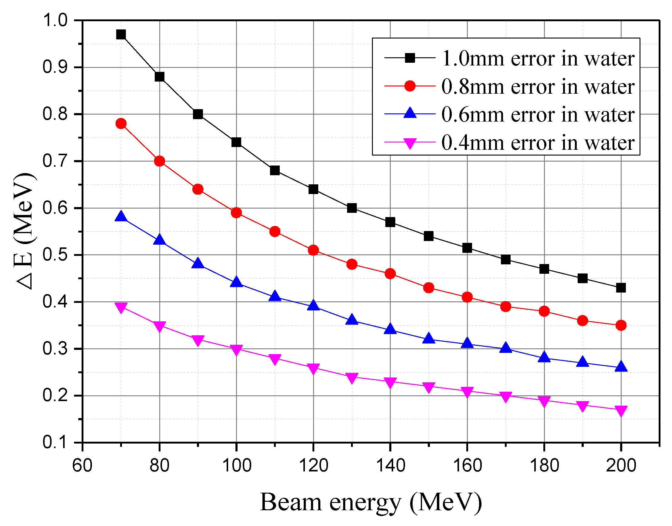
2.1. Energy Validation Requirement

In our project, the cyclotron produces a proton beam with a fixed energy of 200 MeV. Therefore, an energy selection system (ESS) is employed to change energy to match the particle range requirements during treatment. The range-energy relationship can be calculated with Equation (1).
R = α E p ,
where, R is the particle range (unit: cm), E is the kinetic energy (unit: MeV), α ≈ 2.2 × 10⁻³ and p ≈ 1.77 for protons in water [12].
The difference of energy ΔE between the sample and the reference can be expressed as:
Δ E = ( E r p + R s R r α ) p 1 E r ,
where, Rr is the range of reference particle, Er is the kinetic energy of reference particle, Rs is the range of sample particle. Since RsRr ≤ 1 mm, the maximum difference of energy ΔEmax is given as:
Δ E max = ( E r p + 0.1 α ) p 1 E r .
According to Equation (3), the threshold of 1 mm range with different energies can be calculated. Taking a full energy of 200 MeV as an example, the energy verification system must detect if a beam with proton energy outside 200 MeV ±0.43 MeV can reach the patient. In addition, we use different range errors to calculate the energies difference of the kinetic energy, from 70 MeV to 200 MeV. The energy difference under different range errors in water is shown in Figure 3.

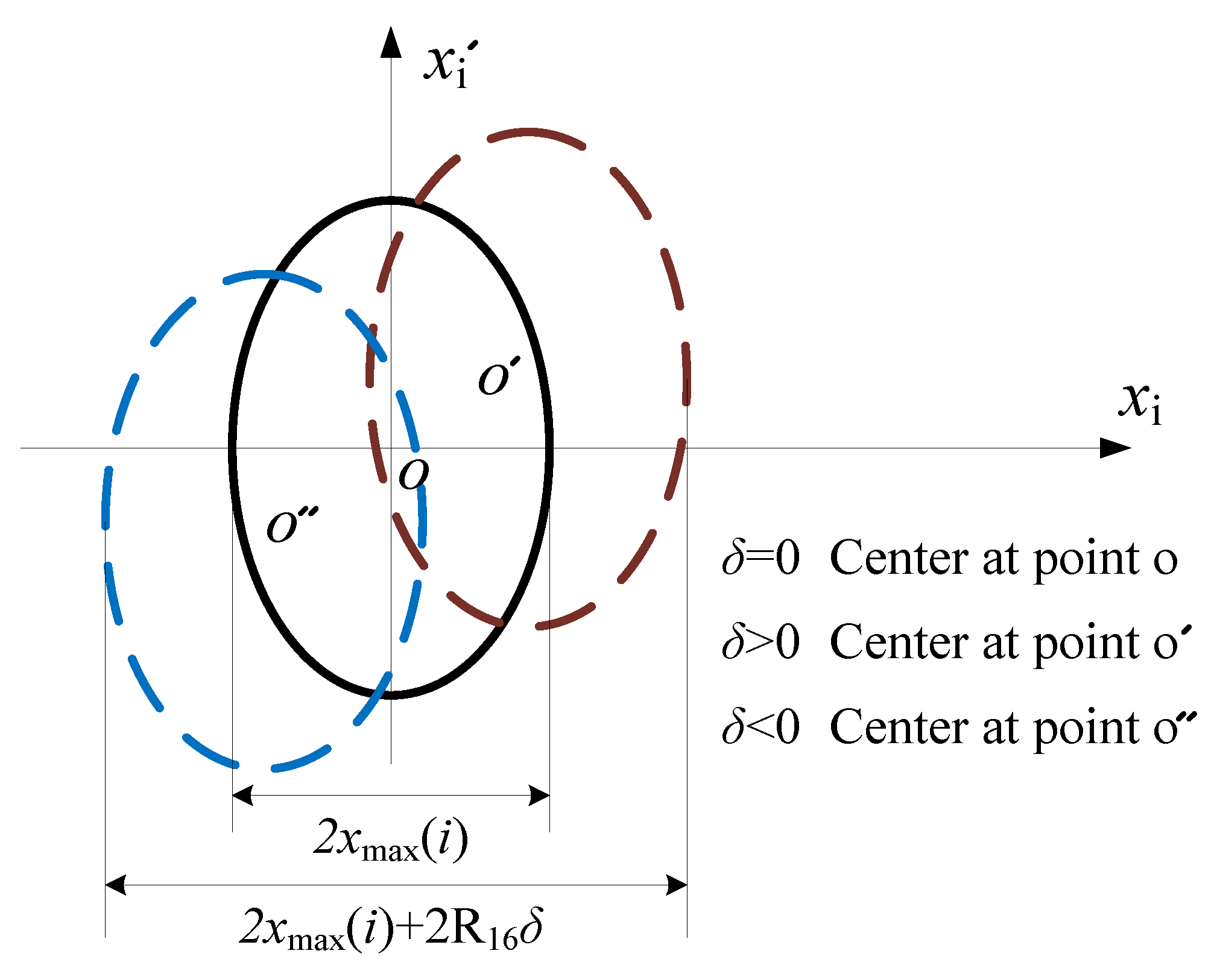
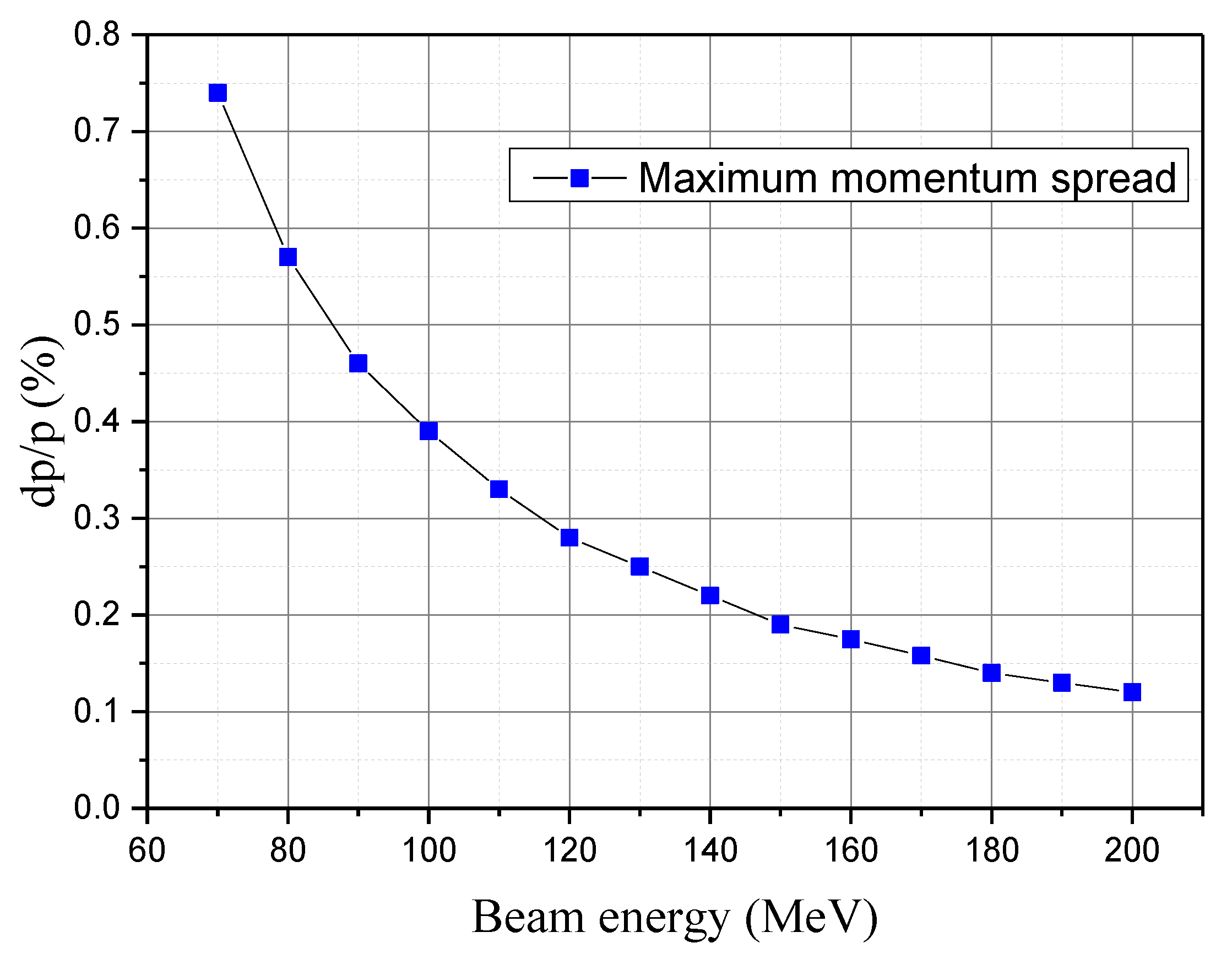
2.2. Momentum Analysis Requirement

When the difference of energy between sample particle and reference particle are known, the momentum spread (1sigma) can be expressed as:
δ = Δ p p r = p s p r p r = γ s β s γ r β r γ r β r , γ s = γ r ε 0 + Δ E ε 0 ,   γ r = ε 0 + E r ε 0 , β s = 1 1 / γ s 2 , β r = 1 1 / γ r 2 ,
where, ε0 is the rest energy of proton (unit: MeV, ε0 = 938 MeV for protons), γs is the relativistic factor of sample particle, γr is the relativistic factor of reference particle, βs is the relative velocity of sample particle, βr is the relative velocity of reference particle. According to Equation (4), the maximum allowed momentum spread δmax can be obtained. Therefore, when the energy is selected by the ESS, the momentum spread needs to be less than the maximum allowed momentum spread δmax. The maximum allowed momentum spread δmax under different energies is shown in Figure 4. Obviously, at lower beam energy, the measurement requirement for a momentum spectrometer is relatively easier and the full energy of 200 MeV is the most demanding case.

2.3. Principle of Energy Verification

The proton beam reference energy are determined by the response of the field measurement and deflection radius of the dipole, which can be calculated according to Equation (5) [13].
E r = m 0 c 2 [ 1 + ( q B ρ m 0 c ) 2 1 ] ,
where, B is the magnetic strength of the measurement by field probe (unit: Telsa), ρ is the deflection radius of the beam (unit: meter), c is the speed of light (unit: meter/sec), m0 is the mass of proton (unit: MeV/c2, m0 = 938 MeV/c2), q is the charge of proton (unit: Coulombs, q = 1.6 × 10⁻¹⁹ Coulombs). The energy spread is determined by the dispersion and beam transverse position constraint in the limiting slit, to the limits that correspond to 1 mm error in water.

2.4. Energy Verification Calculation

When passing the energy selector dipole, the proton beam deflects under Lorentz force. The magnetic field strength of the dipole is measured by two Hall probes. The deflection radius of the dipole is 1.637 m. Due to the non-uniformity of the dipole magnetic field and the positional limitation of the Hall probe, it is necessary to add a compensation to be equivalent to equal the center field strength of the dipole. The reference beam kinetic energy can be calculated as:
E r = ε 0 [ 1 + ( q ( B + B c ) ρ c ε 0 ) 2 1 ] ,
where, ε0 is the rest energy of proton (ε0 = m0c2 = 938 MeV), Bc is the compensated magnetic field. The magnitude of the compensated magnetic field depends on the position of the Hall probe and the magnitude of the dipole field strength.

3. Magnetic Measurements
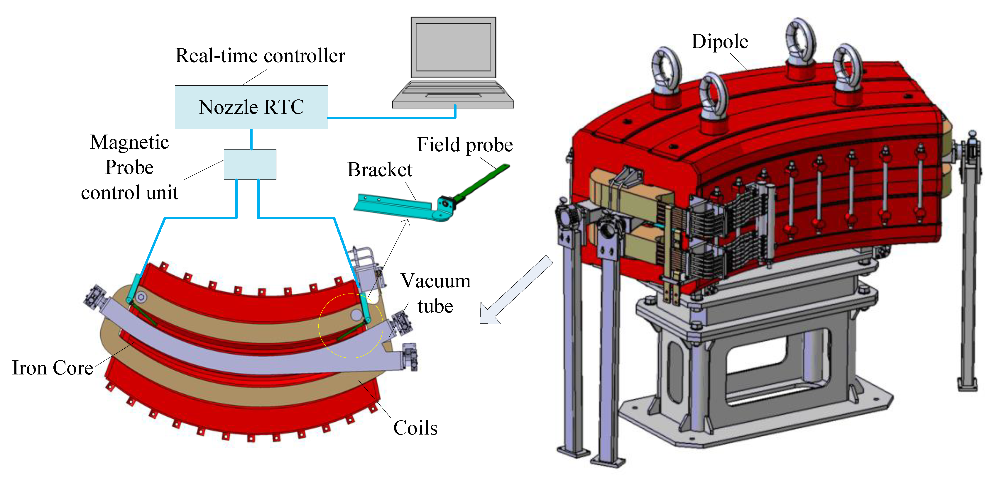
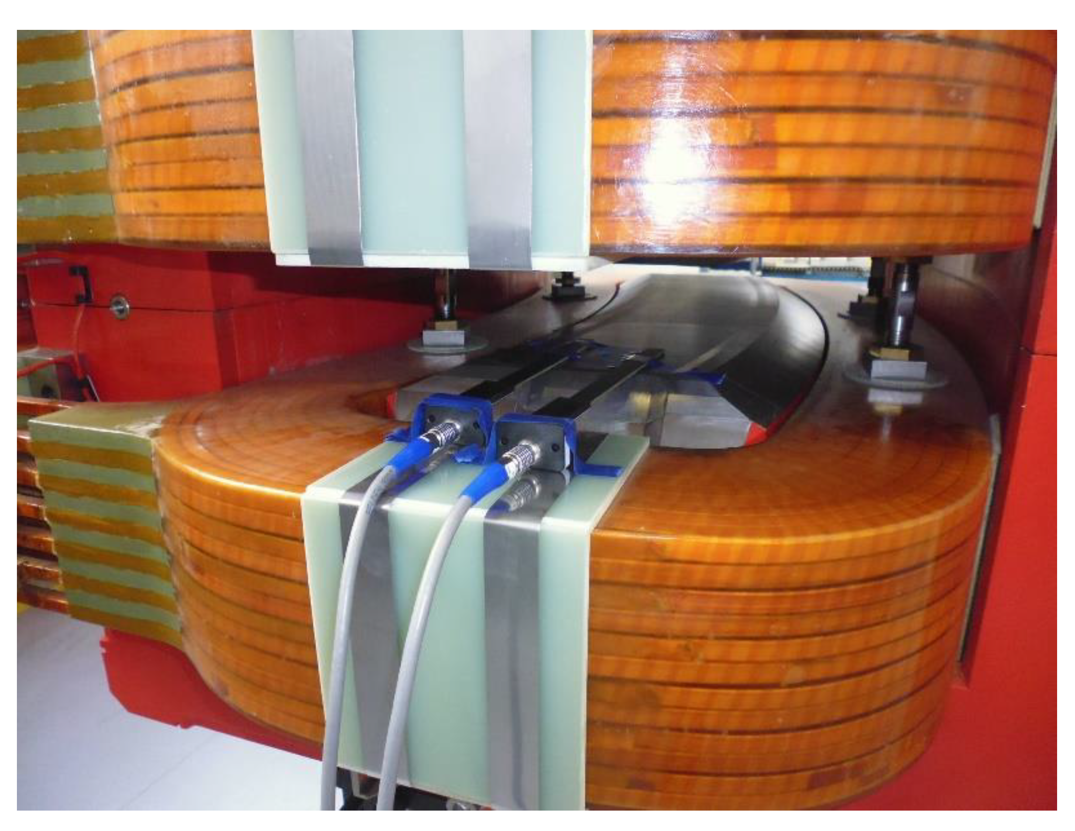
3.1. Dipole Magnet

In our project, the maximum magnetic field strength of the dipole magnet is 1.32 × 10⁴ Gauss, the deflection radius is 1.637 m, the deflection angle is 63 degrees, and the effective length is 1.809 m. The lateral field uniformity and the integration field uniformity of 0.7 × 10⁴ to 1.32 × 10⁴ Gauss are better than ±5 × 10⁻⁴, that is, the field strength difference between the edge trajectory and the central trajectory is 3.5 Gauss to 6.6 Gauss. In order to improve precision and accuracy, two Hall probes are mounted on a dipole magnet to monitor the magnetic field strength in real time, as shown in Figure 5.

3.2. Magnetic Field Probe

The energy verification requirement needs to meet the precision limit that corresponds to 1 mm error in water. The precision of the Hall probe system is an important factor affecting the accuracy of energy verification. The maximum allowable difference between the measured field and the reference is given as:
Δ B max = [ 2 ε 0 + ( E r + Δ E max ) ] ( E r + Δ E max ) ( 2 ε 0 + E r ) E r 299.8 ρ .
We calculate the magnetic field difference according to the above formula. The comparison of the magnetic field difference under different proton energies is listed shown in Table 1. With the increase of the proton energy, the measurement error of the magnetic field has a great influence on the precision of energy validation. Therefore, we have chosen a higher precision Hall probe system for magnetic field measurement. The field range of the Hall probe system is required to be greater than ±1.5 × 10⁴ Gauss, and the field resolution is better than 2 Gauss.

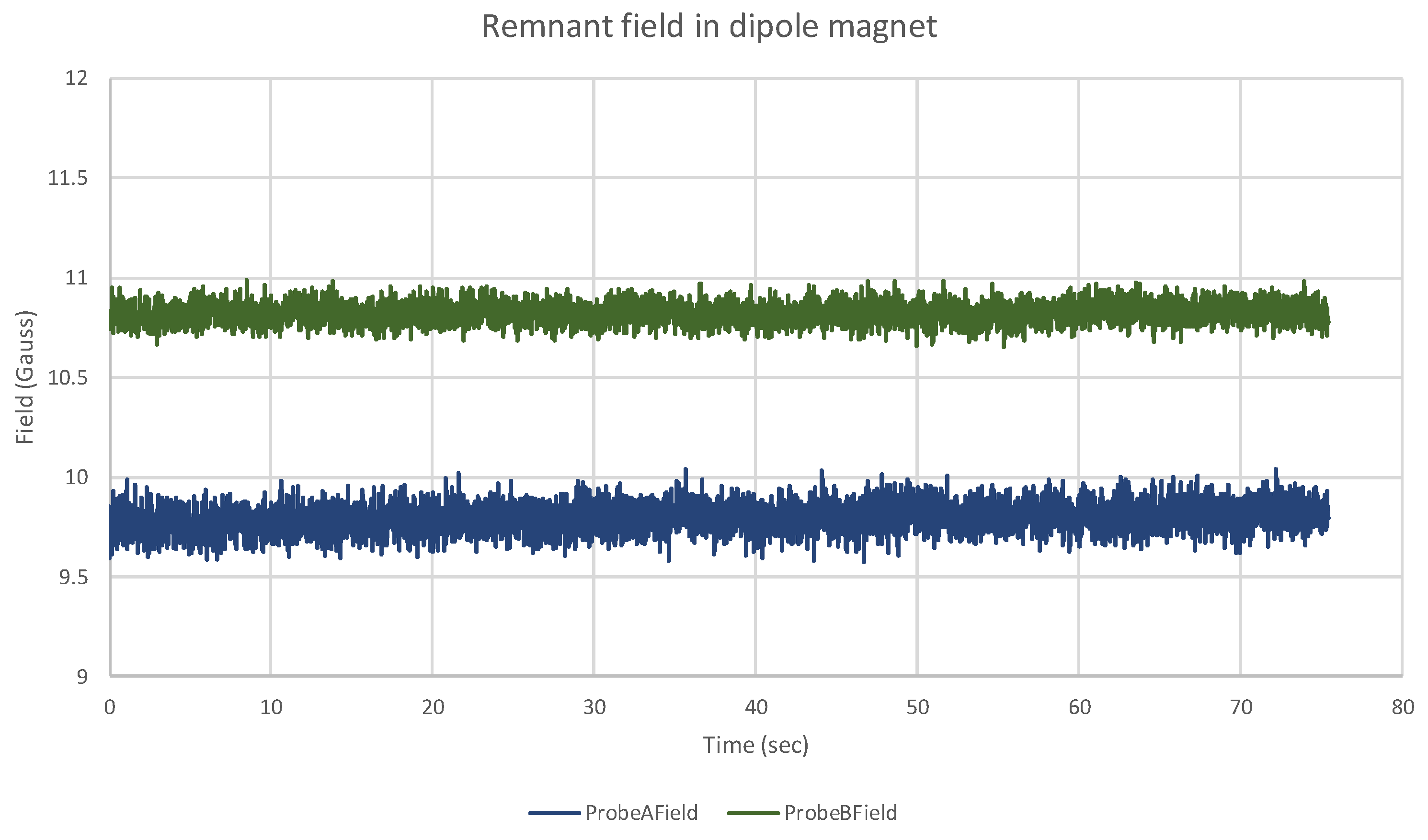
3.3. Test Hall Probe Stability and Accuracy

Unfortunately, the mounting bracket for the Hall probe has not been manufactured. Therefore, we measured the remnant field in a dipole magnet to verify the accuracy and stability of the Hall probe system, as shown in Figure 6.
The test result is shown in Figure 7. The maximum spread in the data is under 0.5 Gauss, which meets the stated stability requirement of 2 Gauss. There were no anomalous readings. At full energy of 200 MeV, the momentum spread of the energy selection system must be less than 0.12% to meet the IEC standard of 1 mm water maximum error. Meanwhile, the reference magnet field is 13131 Gauss at full energy of 200 MeV, this would correspond to a field resolution of 16 Gauss, which is easily met.

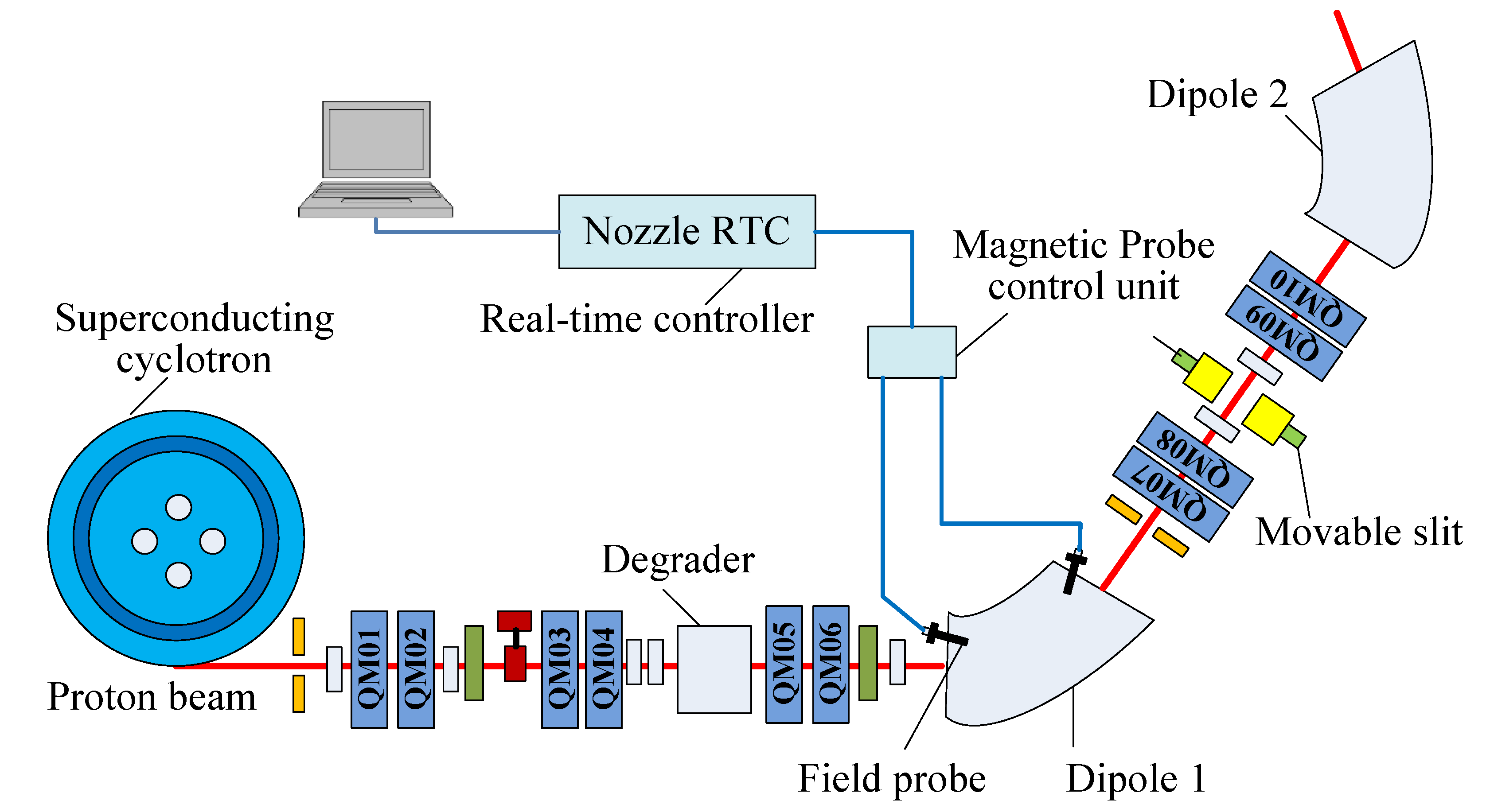
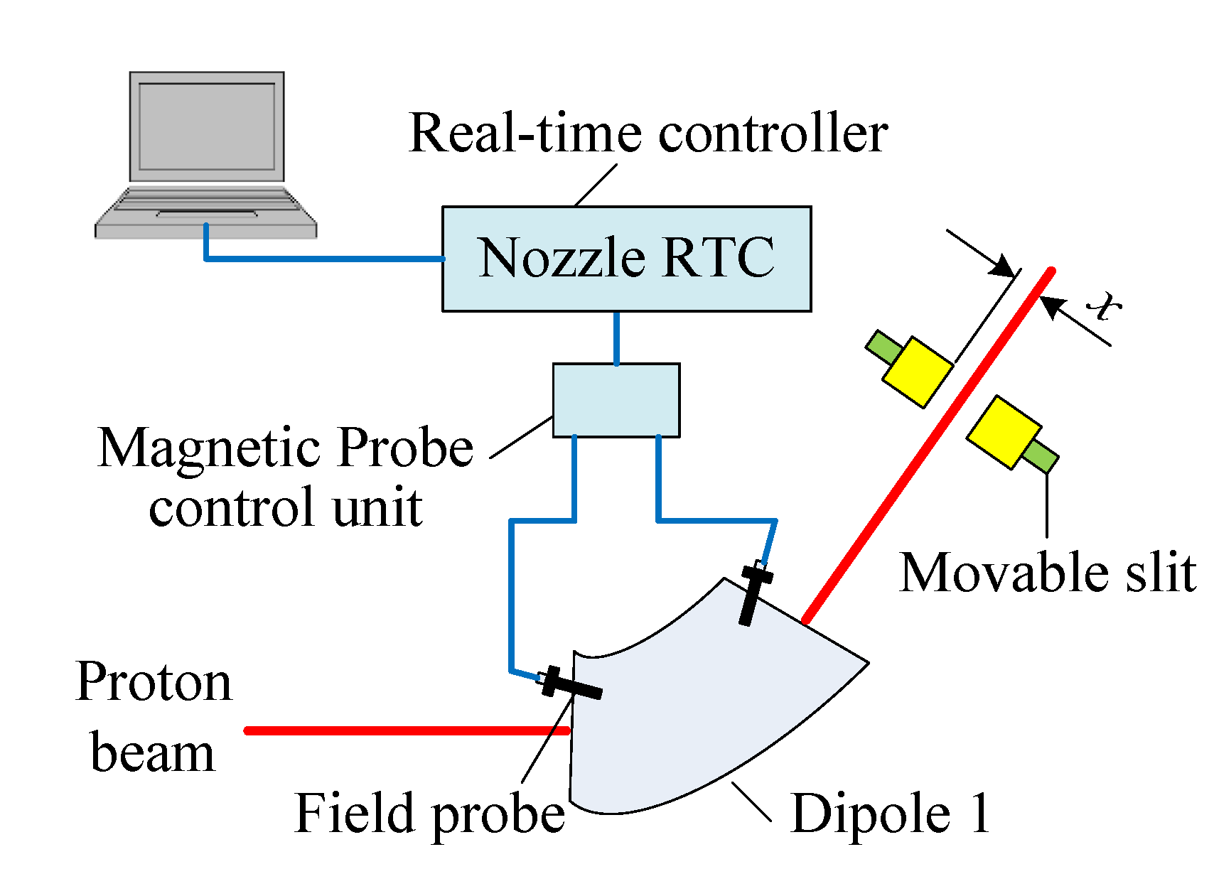
4. Design Scheme of the Energy Verification System

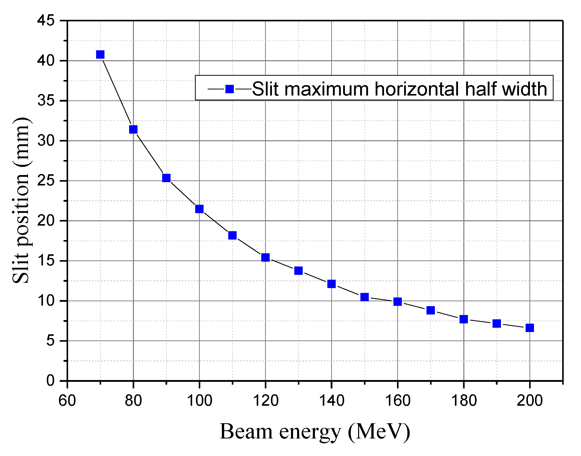
4.1. Momentum Analysis at the Limiting Slit

In the energy selection system of the SC200, the momentum spread is controlled by a movable slit. The movable slit is located in the middle of the two horizontal focusing quadrupoles (QM08 and QM09). As the beam passes through the bending magnets and the quadrupoles, momentum dispersion effect causes center shift of phase ellipse, the dispersion effect is shown in Figure 8.
For beams with momentum pr and pr + Δp, the center distance of such beams can be calculated with Equation (8). The necessary condition for separating them is Δxxmax(i).
Δ x = R 16 δ .
According to the final design, the momentum spread should not exceed 0.1% to 1% depending on the energy. At the movable slit, the correlation between the momentum spread and the horizontal distance(x) was calculated by the computer code TURTLE and TRANSPORT. The position dispersion coefficient R16 is −27.54 mm/% [9].

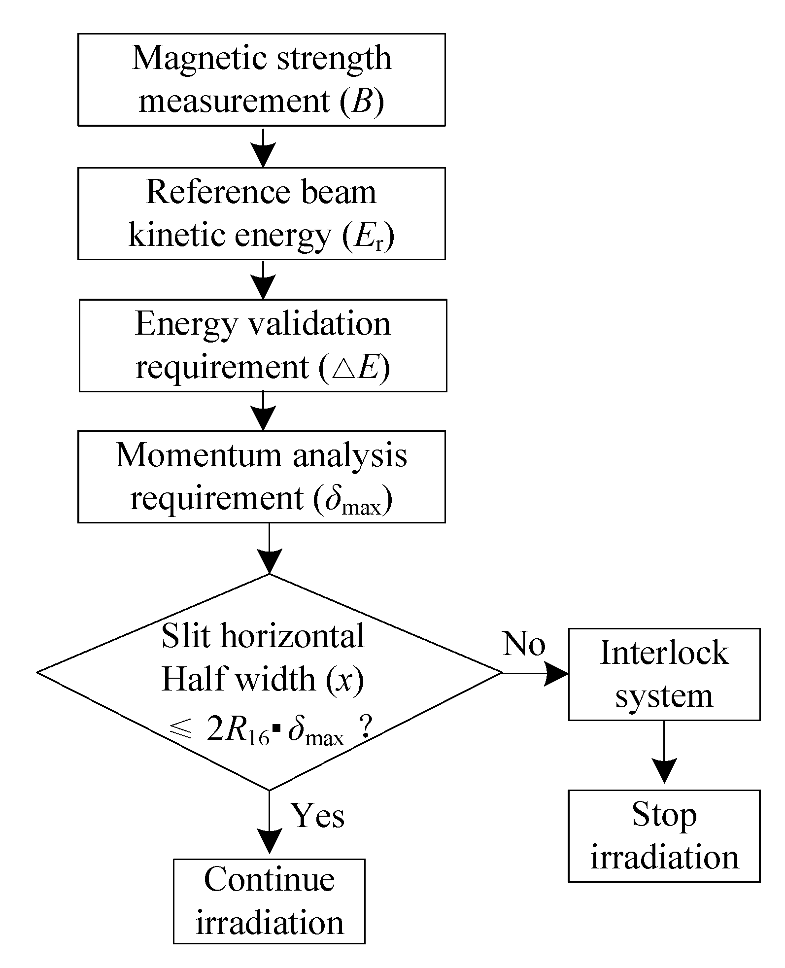
4.2. Energy Verification Scheme

The schematic of the energy verification system for the nozzle in SC200 is shown in Figure 9. Two precision Hall probes are added to the energy selector magnet (dipole 1) at different locations to improve precision and accuracy for energy validation. The stability and accuracy of the Hall probe depends upon temperature, so the Hall probe includes a separate temperature sensor in close thermal proximity to the Hall device, and the compensation is carried out in real time using coefficients stored by the magnetic probe control unit. The magnetic field is sampled, typically at 1 kHz sampling rate. A movable slit is used to restrict the transverse beam position. The real-time Controller (RTC) is intended to provide convenient, high-performance connection of field probe devices via fiber optic loops and real-time processing of the data. Connection to a host computer system is via a standard Ethernet interface. A set of interlock relays allow the RTC to gate external processes based on the incoming data and the state of health of the RTC itself. The proton beam energy is determined by the response of the field measurement plus dispersion and beam transverse position constraint in the ESS.
A flowchart of the process in the energy verification system is shown in Figure 10. Firstly, the beam energies are determined according to the magnetic field tested by the Hall probe. Then, the maximum difference of energy ΔE and the maximum allowed momentum spread δmax are calculated by the clinical requirements that correspond to 1 mm error in water. The energy verification system compares the actual slit position with the target position, if the horizontal half width of the slit is less than or equal to the target position 2R16δmax, irradiation is continued. Otherwise, a signal is sent to the interlock system and the irradiation stops.
The correspondence between the slit maximum positions and the energies selected is shown in Figure 11. The energy selection system must resolve at least δmax 0.12% to meet the IEC standard of 1 mm water maximum error, with a corresponding slit horizontal half width of less than 6.61 mm. During the treatment, the nozzle system needs to obtain the actual position information of the movable slit in real time, and then perform energy verification compared with the maximum allowable position of the slit.

5. Discussion and Conclusions

We calculated the maximum allowed momentum spread that satisfies the energy verification requirements of a proton therapy system, according to IEC60601 standard. The energy verification scheme for the nozzle of the SC200 proton therapy is designed. In order to improve precision and accuracy, two Hall probes are mounted on a dipole magnet, and the beam energies are determined based on the magnetic field monitored by the Hall probe. Meanwhile, the momentum dispersions at the corresponding energies are verified by combining the dispersion and the movable slit horizontal width. Furthermore, the Hall probe system is tested, and the results meet the requirements. Finally, we calculate the target slit positions at the corresponding energies and give an energy verification method.

Author Contributions

Conceptualization, P.W., J.Z. and Y.S.; investigation, W.Z and M.W.; Formal analysis, P.W.; writing—original draft preparation, P.W. and M.W.; writing—review and editing, P.W.

Funding

This research was supported in part by the Major Science and Technology Projects of Anhui under Grant 17030801003 and in part by the Natural Science Research Project of Anhui University under Grant KJ2016A199.

Acknowledgments

The authors are grateful for the support from Hefei CAS Ion Medical and Technical Devices Co., Ltd.

Conflicts of Interest

The authors declare no conflict of interest.

References

  1. Lomax, A. Intensity modulation methods for proton radiotherapy. Phys. Med. Biol. 1999, 44, 185–205. [Google Scholar] [CrossRef] [PubMed]
  2. Shtemberg, A.S.; Kokhan, V.S.; Kudrin, V.S.; Matveeva, M.I.; Bazyan, A.S. The effect of high-energy protons in the Bragg Peak on the behavior of rats and the exchange of monoamines in some brain structures. Neurochem. J. 2015, 9, 66–72. [Google Scholar] [CrossRef]
  3. Smith, A.R. Proton therapy. Phys. Med. Biol. 2006, 51, 491–504. [Google Scholar] [CrossRef] [PubMed]
  4. Bonnett, D.E. Current developments in proton therapy: A review. Phys. Med. Biol. 1993, 38, 1371–1392. [Google Scholar] [CrossRef]
  5. Smith, A.; Gillin, M.; Bues, M.; Zhu, X.R.; Suzuki, K.; Mohan, R.; Woo, S.; Lee, A.; Komaki, R.U.; Cox, J.D.; et al. The MD Anderson proton therapy system. Med. Phys. 2009, 36, 4068–4083. [Google Scholar] [CrossRef] [PubMed]
  6. Matsuda, K.; Itami, H.; Chiba, D.; Kazuyoshi Saito, E. World-first Proton Pencil Beam Scanning System with FDA Clearance. Hitachi Rev. 2009, 58, 225–231. [Google Scholar]
  7. Karamyshev, O.V.; Bi, Y.F.; Chen, G.; Ding, K.Z.; Karamysheva, G.A.; Morozov, N.A.; Samsonov, E.; Shirkov, G.; Shirkov, S.; Song, Y.T. Beam tracking simulation for SC200 superconducting cyclotron. In Proceedings of the 7th International Particle Accelerator Conference, Busan, Korea, 8–13 May 2016. [Google Scholar]
  8. Jiang, F.; Song, Y.T.; Zheng, J.X.; Zeng, X.H.; Wang, P.Y.; Zhang, J.S.; Zhang, W.Q. Energy loss of degrader in SC200 proton therapy facility. Nucl. Sci. Tech. 2019, 30, 4. [Google Scholar] [CrossRef]
  9. Zeng, X.H.; Song, Y.T.; Zheng, J.X.; Jiang, F.; Li, M.; Zhang, J.S.; Zhang, W.Q.; Zhu, L. Beam optics study for energy selection system of SC200 superconducting proton cyclotron. Nucl. Sci. Tech. 2018, 29, 134. [Google Scholar] [CrossRef]
  10. Kanai, T.; Kawachi, K.; Matsuzawa, H.; Inada, T. Three-dimensional beam scanning for proton therapy. Nucl. Instrum. Methods Phys. Res. 1983, 214, 491–496. [Google Scholar] [CrossRef]
  11. March, B.; Prieels, D.; Bauvir, B.; Sépulchre, R.; Gérard, M. IBA proton pencil beam scanning: An innovative solution for cancer treatment. In Proceedings of the EPAC, Vienna, Austria, 26–30 January 2000. [Google Scholar]
  12. Bortfeld, T. An analytical approximation of the Bragg curve for therapeutic proton beams. Med. Phys. 1997, 24, 2024–2033. [Google Scholar] [CrossRef]
  13. Deng, J.J.; He, G.R.; Ding, B.N.; Cheng, N.A.; Yao, L.B. Energy spectrum measurement of 3.3 MeV LIA IPEB. High Power Laser Part. Beams 1993, 5, 353–358. [Google Scholar]
Figure 1. Schematic of the part of the energy selection system (ESS) in 200 MeV superconducting cyclotron (SC200).
Electronics 08 00541 g001
Figure 2. Nozzle layout principle.
Electronics 08 00541 g002
Figure 3. Energies difference under different range errors in water.
Electronics 08 00541 g003
Figure 4. The maximum allowed momentum spread under different energies.
Electronics 08 00541 g004
Figure 5. Schematic diagram of Hall probe and dipole magnet.
Electronics 08 00541 g005
Figure 6. The remnant field of the dipole magnet is measured by Hall probe system.
Electronics 08 00541 g006
Figure 7. The test result of Hall probe system.
Electronics 08 00541 g007
Figure 8. Momentum dispersion effect.
Electronics 08 00541 g008
Figure 9. Schematic of the energy verification system for the nozzle in SC200.
Electronics 08 00541 g009
Figure 10. A flowchart of the process in the energy verification system.
Electronics 08 00541 g010
Figure 11. The analytical calculation of the correspondence between the slit maximum positions and the energies selected.
Electronics 08 00541 g011
Table 1. Comparison of the magnetic field allowable difference under different proton energies.
Energy
Er (MeV)
Energy Validation Requirement
ΔEmax (MeV)
Magnetic Field Strength
B (Gauss)
Allowable Difference
ΔBmax (Gauss)
700.97752154
900.80857240
1100.68952531
1300.601040726
1500.541123422
1700.491201919
1900.451276817
2000.431313116

