Article

An Improved Hierarchical WLAN Positioning Method Based on Apriori Knowledge

1
Department of Information Management, National Yunlin University of Science and Technology, Douliu 64002, Taiwan
2
Chunghua Telecom and Data Communications Business Group, Taipei 10048, Taiwan
*
Author to whom correspondence should be addressed.
Electronics 2019, 8(5), 475; https://doi.org/10.3390/electronics8050475
Submission received: 7 April 2019 / Revised: 24 April 2019 / Accepted: 25 April 2019 / Published: 29 April 2019
(This article belongs to the Section Computer Science & Engineering)

Abstract

:
The hierarchical-based structure is recognized as a favorable structure for wireless local area network (WLAN) positioning. It is comprised of two positioning phases: the coarse localization phase and the fine localization phase. In the coarse localization phase, the users’ positions are firstly narrowed down to smaller regions or clusters. Then, a fingerprint matching algorithm is adopted to estimate the users’ positions within the clusters during the fine localization phase. Currently the clustering strategies in the coarse localization phase can be divided into received signal strength (RSS) clustering and 3D clustering. And the commonly seen positioning algorithms in the fine localization phase include k nearest neighbors (kNN), kernel based and compressive sensing-based. This paper proposed an improved WLAN positioning method using the combination: 3D clustering for the coarse localization phase and the compressive sensing-based fine localization. The method have three favorable features: (1) By using the previously estimated positions to define the sub-reference fingerprinting map (RFM) in the first coarse localization phase, the method can adopt the prior information that the users’ positions are continuous during walking to improve positioning accuracy. (2) The compressive sensing theory is adopted in the fine localization phase, where the positioning problem is transformed to a signal reconstruction problem. This again can improve the positioning accuracy. (3) The second coarse localization phase is added to avoid the global fingerprint matching in traditional 3D clustering-based methods when the stuck-in-small-area problem is encountered, thus, sufficiently lowered the maximum positioning latency. The proposed improved hierarchical WLAN positioning method is compared with two traditional methods during the experiments section. The resulting positioning accuracy and positioning latency have shown that the performance of the proposed method has better performance in both aspects.

1. Introduction

Location is the basis for a large amount of smart applications, e.g., location-based service (LBS). However, as the signals from global positioning system (GPS) are generally blocked or existing severe multi-path in the indoor environment, satellite-based positioning fails to work efficiently indoors. A bunch of positioning methods can be adopted instead for the indoor environment, for example, ultra wide band (UWB)-based [1], radio frequency identification (RFID)-based [2], ultra sound-based [3], bluetooth low energy (BLE)-based [4], wireless local area network (WLAN)-based [5,6] and so on. Among the many existing indoor positioning methods, WLAN-based positioning has great potential for practical applications for the following three reasons:
  • WLAN-based positioning relies on existing access points (APs) commonly seen in many public indoor environments, while many others rely on pre-install infrastructures and are not cost efficient for large scale usage.
  • WLAN-based positioning does not ask for extra hardwares on the user side. The user can locate themselves with only a commonly seen WLAN-enabled devices.
  • The users can help improve the positioning accuracy by contributing their collected data, thus, making the positioning system organic [7].
Currently, most WLAN-based positioning adopt the fingerprinting-based two stage positioning flow [8]. The first phase is the training phase and the second phase is the positioning phase. In the first phase, the received signal strength (RSS) from different APs (also denoted as RSS fingerprints) are collected at some reference points (RPs) in the positioning area. These RSS fingerprints along with known positions are adopted to build a reference fingerprint map (RFM), also denoted as radio map (RM). In the second phase, after the RFM is ready, the newly collected fingerprints from users equipped with smart devices are compared against the fingerprints in the RFM to estimate the users’ or devices’ positions. The underlying assumption for fingerprinting-based WLAN positioning is that the vicinity relationship is kept across fingerprint space (signal space) and 3D space (coordinate space) [8]. From this point of view, the positioning phase is essentially finding similar fingerprints so that the corresponding 3D positions can be adopted as estimations for the users’ locations.
The principle for positioning is simple, however, many factors should be taken into account in designing the positioning method in practical applications. Two major considerations are:
  • Scalability. In real scenario applications, the RFM can be very large in RP number and can across different floors. After the new RSS fingerprint is collected, it may take a long time to search for the matching fingerprint in the RFM. The latency in positioning can render the positioning results unusable. Therefore, the positioning method should be robust to the scalability of the RFM.
  • Accuracy. This is a common consideration for different positioning systems. In WLAN-based positioning, itis preferable that the results are accurate in 3-D position estimation including the floor number and the horizontal position estimations.
A commonly seen WLAN positioning framework considering the mentioned two factors is to cluster in the training phase and to partition the positioning phase into coarse localization and fine localization. The framework can also be denoted as hierarchical positioning. As shown in Figure 1, in the training phase the fingerprints are clustered into small batches. For each of the clusters, a cluster center or examplar is formed. In the positioning phase, the newly collected fingerprint is firstly compared with the cluster centers (cluster matching) to find some potential clusters the fingerprint belong (coarse localization). Then, all fingerprints within the potential clusters are extracted to form a sub-RFM. The fine positioning is carried out adopting the sub-RFM. As the number of fingerprints in the sub-RFM is generally much smaller than that of the whole RFM, the searching/matching time is substantially shortened. Therefore, the clustering-positioning implementation have solved the scalability problem. In addition, as the coarse localization can narrow the searching range and thus, can get rid of some wanted outliers, the localization accuracy can generally be improved [9].
There are many methods adopting the clustering-positioning implementation. Through the different domains, the clustering is carried out, these methods can be partitioned into two categories: RSS clustering and 3D clustering [10]. For the 3D clustering category, the clustering is carried out in the coordinate space, where the fingerprints collected in nearby positions are considered as a cluster. In [10,11], the 3D clustering is carried out using k-means clustering. The previous estimated position can be adopted to find out the potential clusters in the coarse localization. In this way, the prior information for localization is adopted, which implies that users’ positions is somewhat continuous. However, a problem is raised here that large errors from current estimation will affect the accuracy of subsequent estimates because the potential clusters may be stuck in a small area. This is solved in [10] by adding a global search process if the newly collected fingerprints are significantly different from those in the potential clusters. This can greatly improve the positioning accuracy, however, global search may introduce significant latency. In the RSS clustering category, the clusters are generated though clustering in the RSS space. Different clustering strategy is adopted in different methods, such as k-mean, affinity propagation in [12,13]. Generally, affinity propagation works better than k-means for RSS clustering and no prior cluster numbers are needed. Affinity propagation creates clusters by sending messages between pairs of samples until convergence [14]. After RSS clustering, there are also different methods in coarse localization and fine localization. For example, kNN [15], kernel based [16] and compressive sensing-based [17,18]. Among them, compressive sensing-based methods are reported to have better accuracy than the other two. However, as this type of methods normally overlook the information provided by adjacent position estimations, the accuracy is reported to be worse than 3D clustering [10]. Table 1 shows the respective comparisons of 3D clustering and RSS clustering. In summery, the 3D clustering has better positioning accuracy than the RSS clustering because prior position information is adopted. RSS clustering is better than 3D clustering in terms of robustness because 3D clustering may break the hierarchical positioning structure once in a while and having unstable latencies.
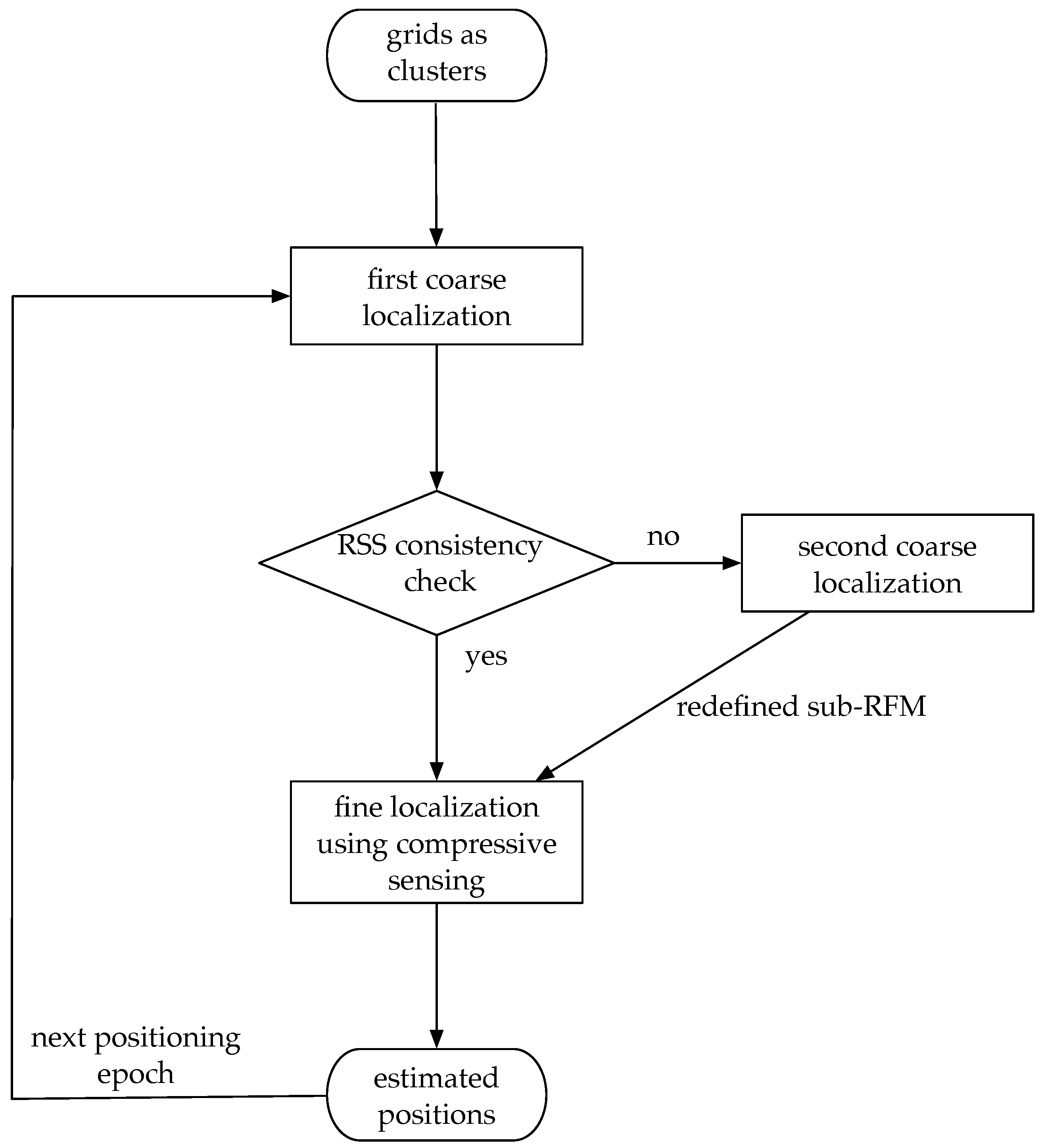
An improved hierarchical WLAN positioning method is proposed in this paper. The method can combine the advantages of traditional 3-D clustering and RSS clustering. The existing RFM is firstly partitioned into fixed size grids as clusters, which can avoid the exhaustive clustering process. Then in the coarse localization phase, the previously estimated position is adopted to find the potential clusters as sub-RFM. If the modified Jaccard distance between the newly collected fingerprint and the sub-RFM is over a threshold, the sub-RFM is defined again by RSS fingerprint matching adopting the mentioned Jaccard distance. Finally, in the fine localization phase, the compressive sensing theory is adopted to increase the positioning accuracy. Figure 2 shows the overall structure of the proposed method. It should be noted that the proposed method has adopted the information from previously estimated positions and can avoid global fingerprint matching. The overall structure is only simply introduced here. More details will be introduced in the Method section. Experiments are carried out and show that the proposed method is better than many existing methods in terms of accuracy.

2. Related Work

2.1. Hierarchical Positioning

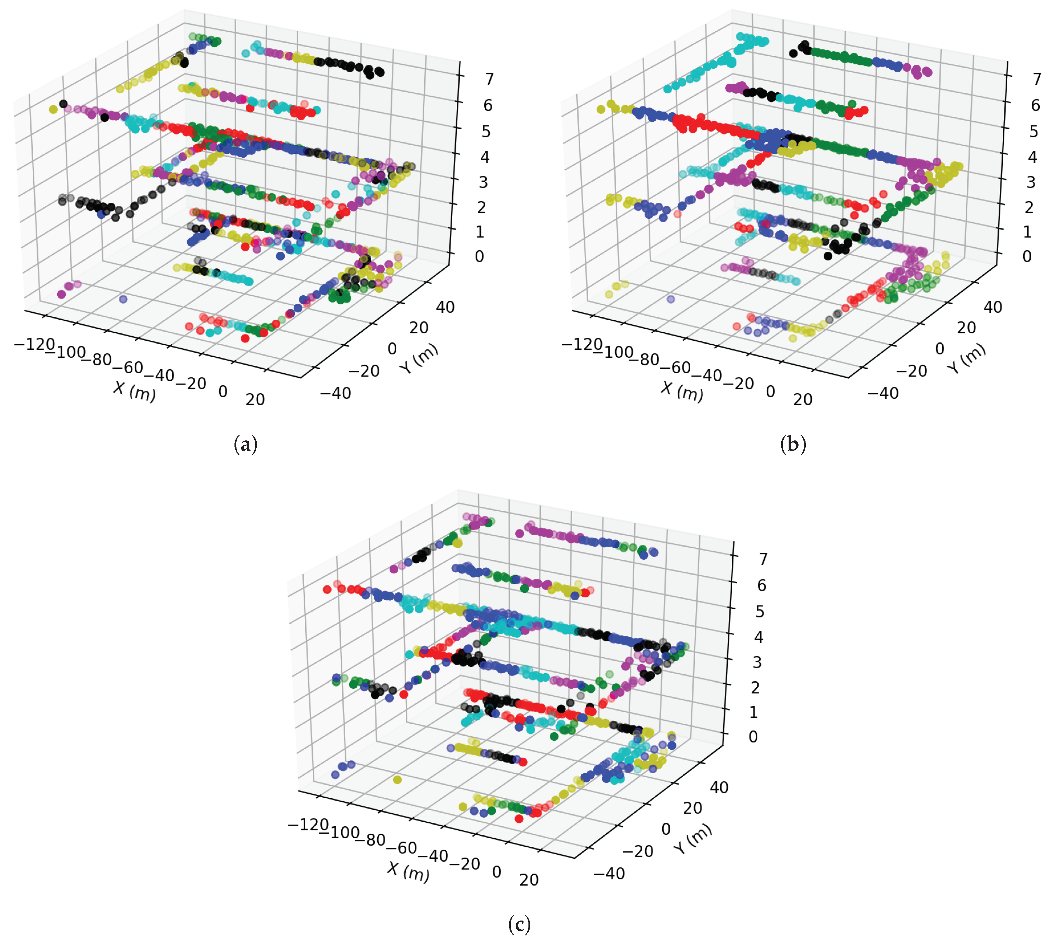
As mentioned before, the hierarchical positioning structure has a two-step positioning phase: coarse localization and fine localization. The advantage of doing so can lower the positioning latency if the RFM has a large number of fingerprints. Moreover, it can improve accuracy by narrowing the searching scope from the whole RFM to a relatively smaller sub-RFM, thus, helping ruling out some fingerprints which can be falsely matched. To enable the coarse localization, the whole RFM should be grouped by clusters or batches. Some methods propose to group the fingerprints by clustering over the RSS readings [9,13] (RSS clustering). An example is shown in Figure 3a, where the clusters come from affinity propagation. Some methods propose to group the fingerprints by clustering in the coordinate domain [10,19]. Figure 3b shows the 3D clustering results from k-means and Figure 3c shows the 3D clustering results by simply using grids.
An examplar in each cluster is needed for fingerprint matching to find out some potential clusters or sub-RFM. Then, in the fine localization step, the newly collected fingerprint only need to be matched within the much smaller sub-RFM.

2.2. Fingerprinting-Based Positioning Algorithms

In fingerprinting-based positioning, it is assumed that the vicinity in RSS domain is also held true in coordinate domain. By matching the newly collected fingerprint against the fingerprints in the RFM, the position where the fingerprint is collected recently can be determined. The simplest form for such an algorithm is the kNN algorithm in [15]. The positions are estimated as the average or the weighted average of the positions with k nearest distance in RSS domain. More algorithms have been proposed to improve the accuracy. The maximum a posteriori (MAP) algorithm proposed in [20] is proved to be more accurate than kNN. In the MAP algorithm, the posteriors that the user is in different positions with known fingerprints and RFM is compared. Then, the position with the maximum posterior is chosen as the position estimation. Kernel tricks and the Bayesian theory are both adopted in calculating the posteriors. Hence, the MAP algorithm in the context of WLAN positioning is also called kernel based algorithms. Compressive sensing-based algorithms can also be adopted for fingerprinting-based positioning. The theory of compressive sensing shows the possibilities for recovering a signal from far less samples than required by the Nyquist sampling theory. Specifically, by adopting the prior information that the signal is sparse in some domain, the signal can be recovered by optimization using the L 1 constrain. The compressive sensing theory is adopted in the context of fingerprinting-based positioning in [17,18], which shows better positioning accuracy than kNN and kernel based algorithms.

3. The Proposed Method

The overall structure of the proposed method is shown in Figure 2. The main steps of the proposed method are:
  • Group the RFM into grids as clusters. This can be considered as the mentioned 3-D clustering because the clustering is done in the coordinate domain. The difference is that instead of using some specific clustering method like k-means, we consider the grids as natural clusters. Hence, there is no need for running the exhaustive clustering process.
  • First coarse localization adopting previously estimated positions. Each time a position estimation is available from fine localization, we find the grids which are close to the previous position estimations and form the sub-RFM. The sub-RFM can then be ready for fine localization. In this way, the information that the estimated positions should be continuous is adopted. The adoption of such information has the possibility for enhancing positioning accuracy.
  • RSS consistency check. As mentioned before, if the previously estimated position has relatively large errors, the sub-RFM extracted from the first coarse localization may not cover the actual matched fingerprint. Moreover, subsequent estimations may also result in large errors. This can be seen as the position estimations are stuck in the false extracted sub-RFM. The aim of RSS consistency check is to detect such a situation. This is achieved through comparing the RSS consistency between the newly collected fingerprint and the fingerprints in the extracted sub-RFM adopting a modified Jaccard distance metric (explained later).
  • Second coarse localization. If the RSS consistency check step suggests that the position estimation is stuck in falsely extracted sub-RFM, we proceed this step. The newly collected fingerprint is then compared against the examplars in all clusters using the modified Jaccard distance and extract the new sub-RFM.
  • Fine localization using compressive sensing. The newly collected fingerprint is compared against all the fingerprints in the sub-RFM adopting the compressive sensing method. The reconstructed signal vector is sparse and each element denotes the extent how the newly collected fingerprint is similar to those in the sub-RFM. The final position estimation is the weighted sum of the positions of the respective similar fingerprints.
The following are the detailed steps of the proposed method.

3.1. Group the RFM into Grids as Clusters

In our implementation, we group the fingerprints in the RFM into grids of size W × W , if the fingerprints are on the same floor. Fingerprints on the different floors are grouped as different clusters. For each of the grid, we form an examplar fingerprint as follows adopting only the availability information of the fingerprints in each grid.
s k = i C k G e t A P ( RSS i )
where the index i denotes the i t h fingerprint, k denotes the k t h grid, the set C k denotes the index set for the fingerprints within the k t h grid, the function G e t A P ( . ) denotes extracting the APs (or Mac addresses) of the respective fingerprint, RSS i denotes the i t h fingerprint, and s k denotes the set of seen APs within the grid k. Equation (1) means that for each grid, the examplar is chosen as the union set of all the seen APs from the fingerprints within the respective grid. How the examplars are used will be discussed later.

3.2. First Coarse Localization

Assuming the previously estimated position can be written as p t 1 , where p t 1 = [ x t 1 , y t 1 , z t 1 ] denotes the 3-D positions. We then find all the grid index k whose coordinate center is within vicinity to p t 1 :
d k , p < D t h r e s
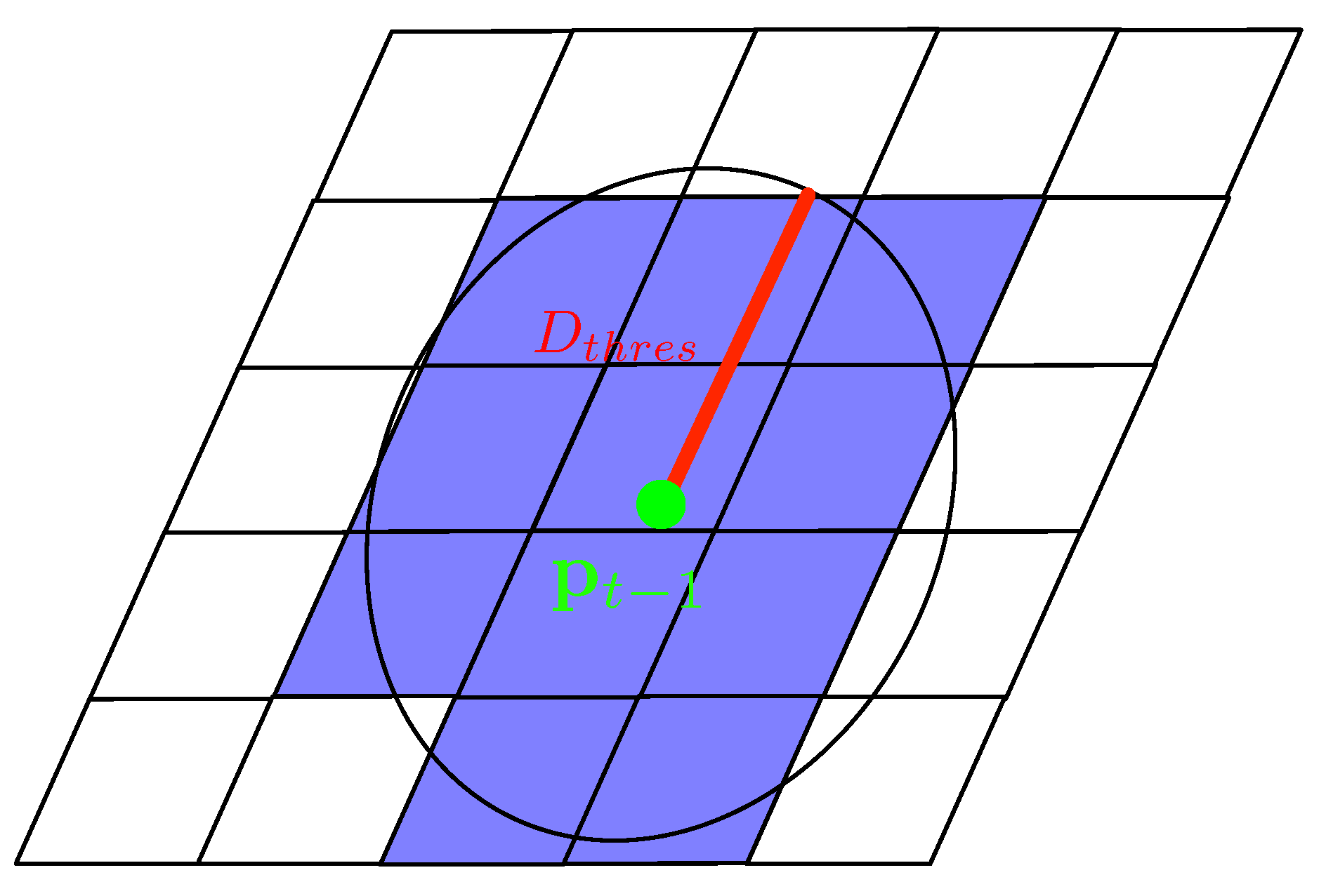
where d k , p denotes the Euclidean distance between the center of the k t h grid and the previously estimated position, and D t h r e s denotes the distance threshold. Compared to the coarse localization using RSS clustering, this is much faster because the distance calculation in the coordinate domain is faster than in the RSS domain, where the RSS signal dimension can be very high. A simple illustration for finding the sub-RFM according to the previously estimated position is shown in Figure 4.

3.3. RSS Consistency Check

As mentioned before, if the positioning error from the previous epoch is large, the sub-RFM from the first coarse localization may be falsely extracted. This will affect subsequent estimations and result in large errors in further positioning. The problem can be solved by comparing the newly collected fingerprint with the fingerprints in the sub-RFM. Here we adopt a modified Jaccard distance as the metric to define the differences in the fingerprints. The modified Jaccard distance is firstly defined in [21]. Due to its computational efficiency and easy scalability [7], it is also adopted here. Assuming there are M grids in the sub-RFM, then we firstly calculate the set of observable APs in the sub-RFM
S sub RFM = i = 1 : M s i
where s i denotes the observable AP set for the i t h grid in the extracted sub-RFM. Then the modified Jaccard distance is defined as
J ( RSS , S sub RFM ) = 1 2 | G e t A P ( RSS ) S sub RFM ) | | G e t A P ( RSS ) S sub RFM | + | G e t A P ( RSS ) S sub RFM | | G e t A P ( RSS ) |
where
  • RSS is the newly collected fingerprint;
  • S sub RFM is the mentioned observable AP set for the sub-RFM from the first coarse localization step;
  • the function G e t A P ( . ) is the as mentioned before, which denote extracting the seen APs of the respective fingerprint;
  • | . | denotes extracting the number of elements in the respective set;
  • ∪ denotes the union operation and ∩ denotes the intersection operation.
There are two terms in Equation (4). The first term defines how the observable APs in either the newly collected fingerprint and the sub-RFM are different. The maximum value for this term reaches 1 if the seen AP sets are the same. The second term gives penalty in the situation that some APs are seen in the newly collected fingerprint but not seen in the sub-RFM. This terms reaches its maximum 1 if all the APs in the newly collected fingerprint can be seen in the sub-RFM. Generally, as the sub-RFM has a larger area while the newly collected fingerprint is just one scan result, if newly collected fingerprint is within the grids of the sub-RFM, it is more likely that some APs are seen in the sub-RFM (but not in the newly collected fingerprint) than vise versa. Generally, the mentioned modified Jaccard distance grows larger if the newly collected fingerprint is from the grids of the sub-RFM. The consistency check is then transformed to a threshold judgement. In our implementation, if
J ( RSS , S sub RFM ) > J thres
we decide that the newly collected fingerprint is within the extracted sub-RFM and the sub-RFM can adopted for the fine localization step. Otherwise we proceed to the second coarse localization step.

3.4. Second Coarse Localization

In the RSS consistency check step, if the check suggests that the sub-RFM is falsely extracted, it can be extracted again in this step. Here we adopt the notion of RSS clustering where the newly collected RSS is used for finding the potential clusters. Here we also adopt the modified Jaccard distance to complete the task. We first calculate the modified Jaccard distance between the newly collected fingerprint and the examplar in each grid is similar to Equation (4)
J i ( RSS , s i ) = 1 2 | G e t A P ( RSS ) s i ) | | G e t A P ( RSS ) s i | + | G e t A P ( RSS ) s i | | G e t A P ( RSS ) |
where s i is the observable AP set for the i t h grid. The sub-RFM is extracted as several grids with largest modified Jaccard distance with the newly collected fingerprint RSS . In our implementation, the potential grid number is chosen as 5.

3.5. Fine Localization

As compressive sensing-based method have better accuracy than simple kNN method and kernel based method for positioning, it is adopted here. The model can be constructed as follows:
RSS = Γ θ + ε
where
  • RSS is the newly collected fingerprint and can be written as:
    RSS = [ r s s 1 , r s s 2 , r s s 3 , , r s s L ] T
    the number L is the number of all APs and each element denotes the RSS from the AP;
  • ε denotes an unknown noise for the RSS;
  • the matrix is with the size of L × N . L is the number of all APs and can be considered as feature dimension. N is the number of the fingerprints in the sub-RFM. The matrix can be written as
    Γ = r s s 1 1 , r s s 1 2 , , r s s 1 N r s s 2 1 , r s s 2 2 , , r s s 2 N r s s L 1 , r s s L 2 , , r s s L N
    the upper index denotes the fingerprint index and the lower index denotes the AP index;
  • θ denotes a vector representing the similarity between the newly collected fingerprint to the respective fingerprint in the sub-RFM. It has the sparse nature. For example, if
    θ = [ 0 , 0 , 1 , , 0 ] T
    it means that the newly collected fingerprint’s coordinate position should be the same as that of the third fingerprint in the sub-RFM.
In Equation (7), the aim is to solve for the θ with known sub-RFM Γ and the newly collected fingerprint RSS . Ideally, θ should have one element equal to 1 and the others 0. This means that the newly collected fingerprint is exactly the same as the one of the fingerprints in the sub-RFM. However, in real scenario, we adopt the all the indices whose normalized value is over a threshold λ
R = { k | θ ˜ ( k ) > λ } w h e r e θ ˜ = θ k = 1 : N θ ( k )
Then the estimated position can by written as the weighted average sum of the respective coordinate positions in the chosen indices of the set R . One of the reasons why θ is not ideal is that some APs are close to each other. This renders that some of the RSS fingerprints highly correlated. This means that the estimated positions are correlated to not one, but many positions where the RSS fingerprints are collected. Same thing will happen if the counterpart kNN and kernel based method are adopted for fine positioning. However, as adopting compressive sensing for positioning are proved to be more accurate than kNN and kernel based methods, it is adopted here.

3.6. Overall Review of the Proposed Method

The proposed method is a combination of 3D clustering for coarse localization and compressive sensing for fine localization. In 3D clustering, the RSS fingerprints are clustered in the coordinate space. Therefore, prior information (a person’s positions are continuous) can be adopted easily by using nearby (in coordinate space) clusters as sub-RFM (Reference Fingerprint Map). From this point of view, 3D clustering is better than RSS clustering. However, accompanying the adoption of prior information, an issue pops up in 3D clustering that the sub-RFM may stuck in small areas due to wrongly estimated positions estimated previously. To solve this problem, the traditional method in [10] proposes to search over all the RFM for matched RSS fingerprints to localize the person again. However, for this method, the hierarchical-based structure is damaged and the positioning latency is significantly increased. The level of positioning latency due to global search is not acceptable in many practical situations. This paper proposed another solution for the stuck-in-small-area problem by adding the RSS consistency check and the second localization procedure to the original hierarchical structure. Overall, by using 3D clustering (including the proposed solution to the issue of 3D clustering) in the coarse positioning phase, there are two advantages. (1) Prior information can be adopted; (2) the stuck-in-small-area issue is solved with less latency than the method in [10].
Then comes to the adoption of compressive sensing in the fine positioning phase. The reason why compressive sensing theory is adopted in our method for fine positioning is simply that it generally has better accuracy than the simple kNN method and kernel based method according to [17,18].

4. Experiments

4.1. Setup

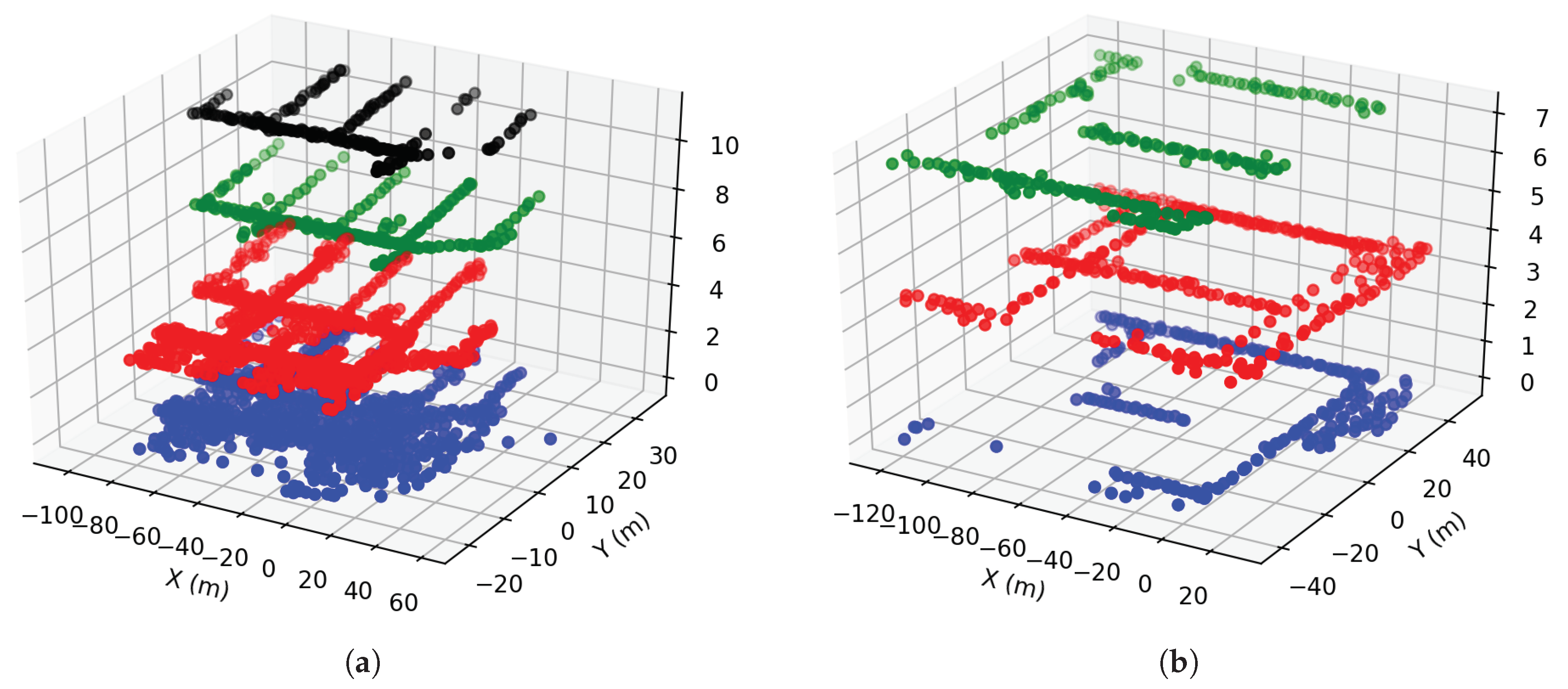
We adopted an open dataset for fingerprinting-based WLAN positioning. The dataset can be found on [22]. The dataset were collected adopting the Nexus tablet. The RFM were established adopting the clicking and interpolation mode. Specifically, the user clicked on the screen showing the respective building map to record the starting and ending points, then coordinate positions of the scanned fingerprints were linearly interpolated. The collected fingerprints were then preprocessed and mapped into 1 m × 1 m grids. During the process, if multiple fingerprints were in the same grid, they were averaged and put to the respective grid. The dataset were collected in two buildings and the 3-D positions of the fingerprints were shown in Figure 5. In Building 1, there were 354 seen APs while the number is 309 in Building 2. More details for the dataset can be found in [10].

4.2. Positioning Accuracy

The dataset in the two buildings are adopted for WLAN-based positioning test. As shown in Table 2, we compare the methods with combinations of different clustering domains and different fingerprinting algorithms. Specifically, the 3D clustering + kernel based positioning were adopted in publication [10], and the RSS clustering + compressive sensing-based positioning were adopted in publication [17]. The proposed method in this paper is method No. 1. Here the different methods are renamed with its numbers for simplicity representation and some of the method descriptions.
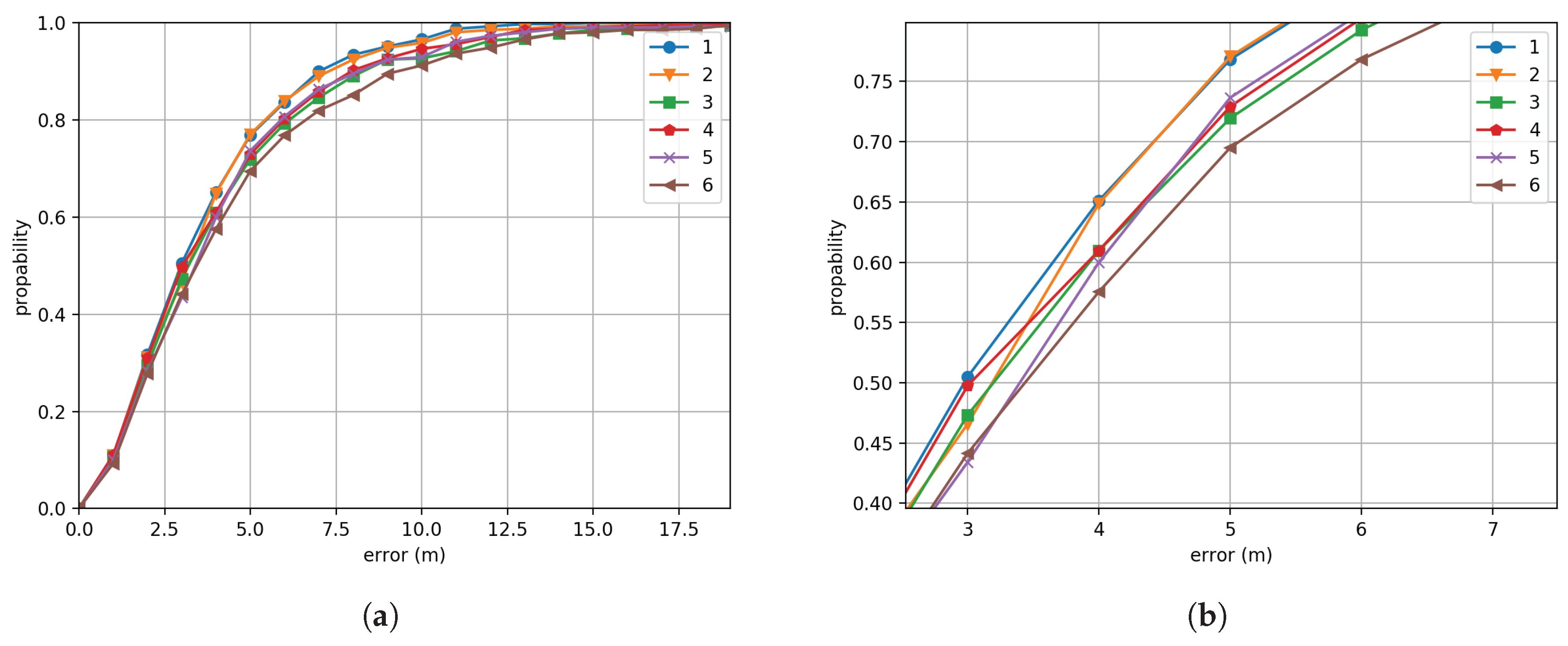
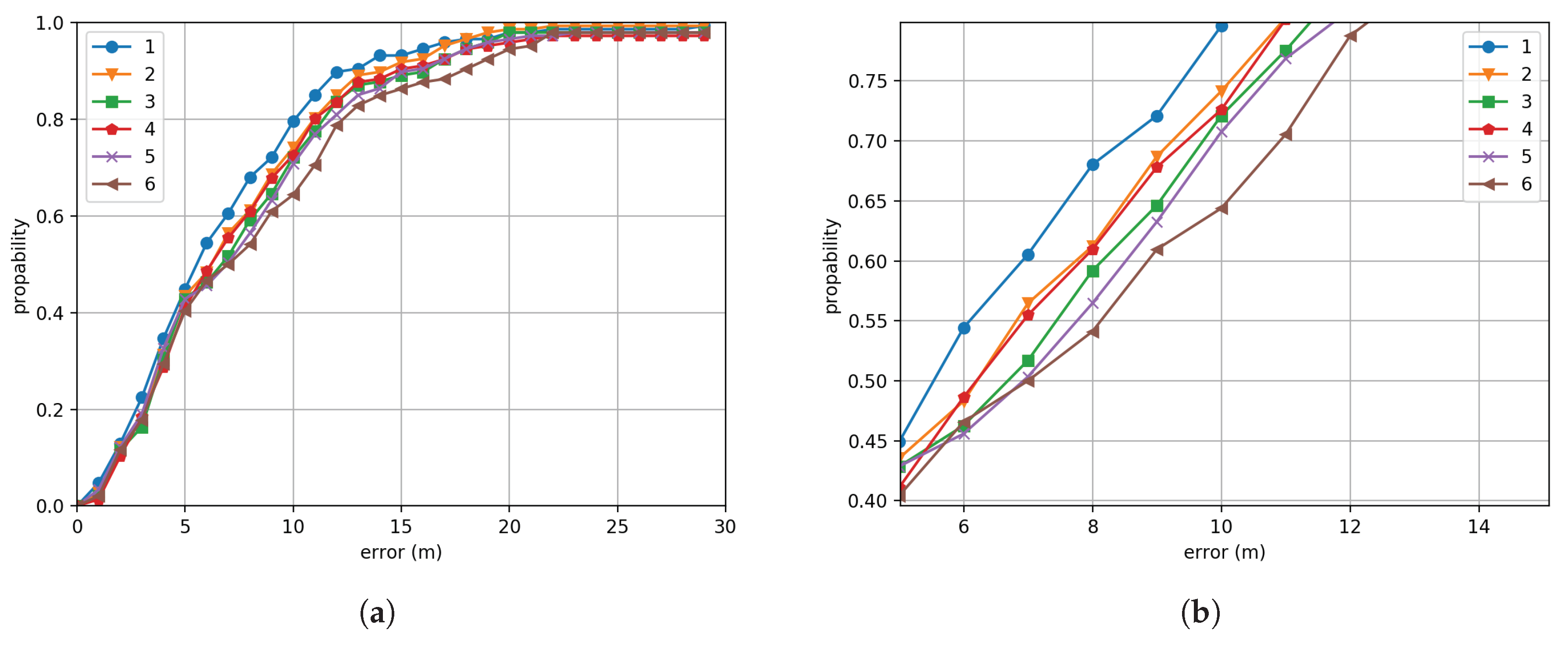
Figure 6 and Figure 7 shows the cumulative density distributions (CDFs) of the positioning errors adopting the different methods in Building 1 and Building 2. Table 3 and Table 4 are the respective error statistics for the two buildings. Both the test in Building 1 and Building 2 have proved that the proposed 3D clustering + compressive sensing combination have better positioning performance than the other combinations. The mean positioning error for the proposed method is 0.1 m less than the typical method 2 (proposed in [10]) and 0.3 m less than method 4 (proposed in [17]) for Building 1. The numbers are 0.5 m and 1.2 m respectively for Building 2. From the comparisons between method 1, 2, 3 and method 4, 5, 6, we can see that 3D clustering is generally better than RSS clustering. This may due to the reason that in 3D clustering, the prior information that the estimated positions should be continuous is adopted. Such information can have a position constraint on subsequent estimations. Therefore, the positioning accuracy is improved over RSS clustering. From the comparisons between method 1, 2, and 3 or method 4, 5 and 6, we can see that for the performance of fingerprinting algorithms, the compressive sensing algorithm is better than kernel based, which again is better than kNN. This is consistent with the conclusion in [17]. The mean error decreasing numbers are shown in Table 5 and Table 6. We can see from the two tables that adopting compressive sensing do have an effect for improving accuracy. However, the improvements differ. For example, in Building 1, the 3D clustering+compressive sensing (method 1) is only 0.1 m less than the combination of 3D clustering+kernel method (method 2), while in building 2, the number is 0.5 m. This means that compressive sensing generally has an improvement for positioning, however, the extent of the improvements differs according to different datasets. One possible reason why positioning accuracies for building 1 and building 2 are at different levels may due to that the collected fingerprint granularity for the two buildings are different. This is also the possible reason that the accuracy improvements of compressive sensing are also different in two buildings. From Figure 5, we can see that the data granularity for Building 1 is better than Building 2. The data granularity can be further improved by interpolation and extrapolation techniques. However, it is regarded another topic and is not studied in this paper.

4.3. Positioning Latency

An importance indicator for an WLAN-based positioning system is the positioning latency. If the available RFM has relatively a small number of fingerprints, the latency would be acceptable for the global fingerprint matching search. However, the searching time grows linearly with the number of available fingerprints in the RFM. To lower the positioning latency, the hierarchal structure is proposed with either RSS clustering and 3D clustering. From the results in Figure 6 and Figure 7, we know that 3D clustering generally has better accuracy than RSS clustering because the prior information is adopted. Here we compare the positioning latency of the proposed method, the traditional 3D clustering-based method ([10]) and the method proposed in [17]. The compared methods correspond to method No.1, No. 2 and No. 4 respectively. Two positioning latency indicator are shown in Table 7: the average latency and the maximum latency. The latter indicator is of the utmost importance in an actual positioning application, because the maximum latency is related to the robustness of the system. Consider this case, as the maximum latency is large, the user may not be able to get a positioning feedback for a long time and may think something is wrong with the positioning system. From Table 7, we can see that the average latency for the three different methods are at the same level. However, for the method No. 2, as the traditional 3D clustering method would engage in global search to solve the stuck-in-small-area issue, the maximum processing time is much larger than the other two methods. While our method has added a second coarse localization procedure to avoid global search and can greatly lower the corresponding maximum latency. For method No. 2, it will become even worse if the the RFM grows larger. Noting that here the latency only considers the processing time for fingerprinting. In actual applications, the latency will grow with other necessary procedures, such as data exchange between the mobile device and the server. For method No. 2, as global search are needed, the RFM should be transferred from the server to the device, this will further increase the positioning latency and render the system not responsive.

5. Conclusions and Discussions

Hierarchical-based positioning partitions the WLAN positioning into coarse localization phase and fine localization phase, and can efficiently decrease the positioning latency, and even improve the positioning accuracy. For the coarse localization phase, two different strategies can be adopted to provide the necessary clusters: RSS clustering and 3D clustering. For the fine localization phase, different positioning algorithms can be adopted, such as compressive sensing, kernel based and simple kNN. This paper have studied the different combinations of the mentioned clustering strategies and positioning algorithms. The paper proposed a novel hierarchical WLAN positioning method with the 3D clustering + compressive sensing combination. The method adopts grid-based clustering and the modified Jaccard distance metric in the first coarse localization phase. To avoid wrong sub-RFM extraction, an RSS consistency check is carried out and then performs the second coarse localization if not passed. At last, the compressive sensing theory is adopted in the fine localization phase. With these procedures, the proposed method can avoid the stuck-in-small-area problem commonly seen in traditional 3D clustering methods. With the experiments carried out, this combination is proved to be more accurate than the traditional 3D clustering method in [10] and the traditional compressive sensing-based method in [17]. Moreover, for the aspect of positioning latency, the proposed method is proved to be more robust than the traditional 3D clustering-based method in [10]. What should be noted here is that the accuracy improvement by adopting compressive sensing over kNN and kernel-based methods is sometimes not so significant, and the extent of accuracy improvement differs over different datasets.
The reasons why the accuracy is superior to [10,17] are two folds:
  • The proposed method has adopted the prior information that the positions of the users are continuous in time.
  • In the fine localization phase, the compressive sensing theory is adopted, which was already proved in [17] to have more accurate positioning results than the simple kNN method and the kernel-based method.
Also, the proposed method can avoid larger positioning latencies in [10]. This is due to the fact that the second coarse localization phase is added if the RSS consistency check is not passed. The positioning is degenerating to the situation where the mentioned prior information is not available. This is different from the strategy in [10], where global fingerprint matching is conducted when similar situations are encountered.

Author Contributions

K.-T.F., C.-T.L. and L.-m.S. have worked together to achieve the work. K.-T.F. and C.-T.L. wrote the paper. L.-m.S. helped performe the experiments together and gave suggestion on the revision of the paper.

Funding

This research received no external funding.

Conflicts of Interest

The authors declare no conflict of interest.

References

  1. Gigl, T.; Janssen, G.J.M.; Dizdarevic, V.; Witrisal, K.; Irahhauten, Z. Analysis of a UWB Indoor Positioning System Based on Received Signal Strength. In Proceedings of the 2007 4th Workshop on Positioning, Navigation and Communication, Hannover, Germany, 22 March 2007; pp. 97–101. [Google Scholar] [CrossRef]
  2. Saab, S.S.; Nakad, Z.S. A Standalone RFID Indoor Positioning System Using Passive Tags. IEEE Trans. Ind. Electron. 2011, 58, 1961–1970. [Google Scholar] [CrossRef]
  3. Ran, L.; Helal, S.; Moore, S. Drishti: An integrated indoor/outdoor blind navigation system and service. In Proceedings of the Second IEEE Annual Conference on Pervasive Computing and Communications, Orlando, FL, USA, 17 March 2004; pp. 23–30. [Google Scholar] [CrossRef]
  4. Zhuang, Y.; Yang, J.; Li, Y.; Qi, L.; El-Sheimy, N. Smartphone-Based Indoor Localization with Bluetooth Low Energy Beacons. Sensors 2016, 16, 596. [Google Scholar] [CrossRef] [PubMed]
  5. Youssef, M.; Agrawala, A. The Horus WLAN Location Determination System. In Proceedings of the 3rd International Conference on Mobile Systems, Applications, and Services, MobiSys ’05, Seattle, WA, USA, 6–8 June 2005; ACM: New York, NY, USA, 2005; pp. 205–218. [Google Scholar] [CrossRef]
  6. Gu, Y.; Zhou, C.; Wieser, A.; Zhou, Z. WiFi based trajectory alignment, calibration and crowdsourced site survey using smart phones and foot-mounted IMUs. In Proceedings of the 2017 International Conference on Indoor Positioning and Indoor Navigation (IPIN), Sapporo, Japan, 18–21 September 2017; pp. 1–6. [Google Scholar] [CrossRef]
  7. Park, J.G.; Charrow, B.; Curtis, D.; Battat, J.; Minkov, E.; Hicks, J.; Teller, S.; Ledlie, J. Growing an Organic Indoor Location System. In Proceedings of the 8th International Conference on Mobile Systems, Applications, and Services, MobiSys ’10, San Francisco, CA, USA, 15–18 June 2010; ACM: New York, NY, USA, 2010; pp. 271–284. [Google Scholar] [CrossRef]
  8. Khalajmehrabadi, A.; Gatsis, N.; Akopian, D. Modern WLAN Fingerprinting Indoor Positioning Methods and Deployment Challenges. IEEE Commun. Surv. Tutor. 2017, 19, 1974–2002. [Google Scholar] [CrossRef] [Green Version]
  9. Youssef, M.A.; Agrawala, A.; Shankar, A.U. WLAN location determination via clustering and probability distributions. In Proceedings of the First IEEE International Conference on Pervasive Computing and Communications, (PerCom 2003), Fort Worth, TX, USA, 26 March 2003; pp. 143–150. [Google Scholar] [CrossRef]
  10. Cramariuc, A.; Huttunen, H.; Lohan, E.S. Clustering benefits in mobile-centric WiFi positioning in multi-floor buildings. In Proceedings of the 2016 International Conference on Localization and GNSS (ICL-GNSS), Barcelona, Spain, 28–30 June 2016; pp. 1–6. [Google Scholar] [CrossRef]
  11. Tao, X.; Li, X.; Ma, J.; Lu, J. Cluster filtered KNN: A WLAN-based indoor positioning scheme. In Proceedings of the 2008 International Symposium on a World of Wireless, Mobile and Multimedia Networks(WOWMOM), Newport Beach, CA, USA, 23–26 June 2008; pp. 1–8. [Google Scholar] [CrossRef]
  12. Razavi, A.; Valkama, M.; Lohan, E. K-Means Fingerprint Clustering for Low-Complexity Floor Estimation in Indoor Mobile Localization. In Proceedings of the 2015 IEEE Globecom Workshops (GC Wkshps), San Diego, CA, USA, 6–10 December 2015; pp. 1–7. [Google Scholar] [CrossRef]
  13. Ding, G.; Tan, Z.; Zhang, J.; Zhang, L. Fingerprinting localizatioN-based on affinity propagation clustering and artificial neural networks. In Proceedings of the 2013 IEEE Wireless Communications and Networking Conference (WCNC), Shanghai, China, 7–10 April 2013; pp. 2317–2322. [Google Scholar] [CrossRef]
  14. Frey, B.J.; Dueck, D. Clustering by Passing Messages Between Data Points. Science 2007, 315, 972–976. [Google Scholar] [CrossRef] [PubMed] [Green Version]
  15. Bahl, P.; Padmanabhan, V.N. RADAR: An in-building RF-based user location and tracking system. In Proceedings of the IEEE INFOCOM 2000, Conference on Computer Communications, Nineteenth Annual Joint Conference of the IEEE Computer and Communications Societies (Cat. No.00CH37064), Tel Aviv, Israel, 26–30 March 2000; Volume 2, pp. 775–784. [Google Scholar] [CrossRef]
  16. Venetsanopoulos, A.N.; Plataniotis, K.N.; Kushki, A. Kernel-Based Positioning in Wireless Local Area Networks. IEEE Trans. Mob. Comput. 2007, 6, 689–705. [Google Scholar] [CrossRef]
  17. Feng, C.; Au, W.S.A.; Valaee, S.; Tan, Z. Received-Signal-Strength-Based Indoor Positioning Using Compressive Sensing. IEEE Trans. Mob. Comput. 2012, 11, 1983–1993. [Google Scholar] [CrossRef]
  18. Chen, K.; Mi, Y.; Shen, Y.; Hong, Y.; Chen, A.; Lu, M. SparseLoc: Indoor Localization Using Sparse Representation. IEEE Access 2017, 5, 20171–20182. [Google Scholar] [CrossRef]
  19. Zou, G.; Ma, L.; Zhang, Z.; Mo, Y. An indoor positioning algorithm using joint information entropy based on WLAN fingerprint. In Proceedings of the Fifth International Conference on Computing, Communications and Networking Technologies (ICCCNT), Hefei, China, 11–13 July 2014; pp. 1–6. [Google Scholar] [CrossRef]
  20. Madigan, D.; Einahrawy, E.; Martin, R.P.; Ju, W.; Krishnan, P.; Krishnakumar, A.S. Bayesian indoor positioning systems. In Proceedings of the IEEE 24th Annual Joint Conference of the IEEE Computer and Communications Societies, Miami, FL, USA, 13–17 March 2005; Volume 2, pp. 1217–1227. [Google Scholar] [CrossRef]
  21. Zhou, C.; Wieser, A. Jaccard Analysis and LASSO-Based Feature Selection for Location Fingerprinting with Limited Computational Complexity. In Progress in LocatioN-based Services 2018; Kiefer, P., Huang, H., de Weghe, N., Raubal, M., Eds.; Springer International Publishing: Cham, Switzerland, 2018; pp. 71–87. [Google Scholar]
  22. Cramariuc, A.; Lohan, E. Open-access WiFi Measurement Data and Python-Based Data Analysis. Available online: http://www.cs.tut.fi/tlt/pos/meas.htm (accessed on 12 February 2018).
Figure 1. The clustering-positioning implementation for fingerprinting-based WLAN positioning.
Electronics 08 00475 g001
Figure 2. The overall processing structure of the proposed hierarchical method.
Electronics 08 00475 g002
Figure 3. An illustration for clusters adopting different strategies for the same dataset. Different colors possibly denotes different clusters. The numbers of clusters are 90, 25 and 79 respectively. (a) RSS clustering using affinity propagation. (b) 3-D clustering using k-means. Fingerprints on different floors can belong to the same cluster here. (c) 3-D clustering using simple grids. Here the grid size is 20 m × 20 m. Fingerprints in different floors are considered belong to different grids.
Electronics 08 00475 g003
Figure 4. The grids within a certain distance threshold D t h r e s to the previously estimated position p t 1 is extracted as the sub-RFM (shown on horizontal plane).
Electronics 08 00475 g004
Figure 5. The dataset adopted in our experiment. Different floors are shown in different colors (a) Building 1 (b) Building 2.
Electronics 08 00475 g005
Figure 6. The CDFs of methods with different combinations for Building 1. The legends number correspondences can be found in Table 2. (a) CDFs (b) Enlarged CDFs.
Electronics 08 00475 g006
Figure 7. The CDFs of methods with different combinations for Building 2. The legends number correspondences can be found in Table 2. (a) CDFs (b) Enlarged CDFs.
Electronics 08 00475 g007
Table 1. Feature comparisons for 3D clustering and RSS clustering.
FeaturesAccuracyRobustness
3-D clusteringbetterworse
RSS clusteringworsebetter
Table 2. Methods with different combinations of clustering domains and fingerprinting algorithms.
NumberMethodMethod Description
13D clustering + compressive sensing-basedproposed in this paper
23D clustering + kernel basedtraditional 3D clustering method in [10]
33D clustering + kNN×
4RSS clustering + compressive sensing-basedtraditional compressive sensing method in [17]
5RSS clustering + kernel based×
6RSS clustering + kNN×
Table 3. The errors for different WLAN positioning methods for Building 1.
Method NumberMean (m)75% Error (m)RMS (m)
13.64.82.6
23.74.82.8
34.15.43.4
43.95.33.1
54.15.23.4
64.45.83.6
Table 4. The errors for different WLAN positioning methods for Building 2.
Method NumberMean (m)75% Error (m)RMS (m)
16.79.45.1
27.210.15.1
38.010.56.9
47.910.37.1
58.010.66.7
68.611.57.2
Table 5. The mean error decreasing numbers using compressive sensing over kNN and kernel based methods in building 1.
Error DecreaseOver Kernel Based Method (m)Over Kernel Based Method (%)Over kNN (m)Over kNN (%)
3D clustering0.13%0.511%
RSS clustering0.25%0.512%
Table 6. The mean error decreasing numbers using compressive sensing over kNN and kernel based methods in building 2.
Error DecreaseOver Kernel Based Method (m)Over Kernel Based Method (%)Over kNN (m)Over kNN (%)
3D clustering0.57%1.316%
RSS clustering0.11%0.78%
Table 7. The latency comparisons for the different methods.
Method NumberAverage Latency (ms)Maximum Latency (ms)
18.215.5
215.5320.8
411.818.4