1. Introduction
Filters play a very important role in many microwave and radio frequency (RF) applications. Burgeoning applications such as wireless communication systems continue to challenge microwave/RF filters with even more stringent requirements [
1]. At the same time, with the rapid development of the fifth-generation (5G) mobile communication technology, wideband wireless communication systems are also being widely developed and applied, because of their high transmission rate, low power consumption, high security and anti-interference ability. Therefore, wideband bandpass filters (BPFs) have received tremendous attention as a key and essential passive component in wideband wireless communication systems. Recently various methods and techniques for the design of wideband BPFs are constantly being presented. However, up until now the design of the wideband BPFs with compact size, high selectivity, low cost, wide stopband and high power capacity is still a challenging task. Traditional transmission line technologies, whether planar or non-planar, cannot fully meet all of these requirements. Fortunately, a structure called a wideband substrate integrated waveguide (SIW), which combines the characteristics of both planar and non-planar circuits, has emerged and developed extensively due to its potential applications to the design of excellent filters [
2]. However, the typical bandwidths of these filters based on SIW technology are very narrow, generally less than 20% or even 15% [
3]. In [
4], a modified SIW zigzag filter topology is proposed to achieve the wideband feature. But the circuit size is large for engineering applications and its fractional bandwidth is still only 28%. In order to improve the compactness of a wideband SIW filter, the ridge half-mode SIW (RHMSIW) structure is presented in [
5], which provides the implementation to design wideband filter of quite a small size. Although the aforementioned improvement is substantial, the RHMSIW BPF has narrow stopband region and low selectivity. In [
6], a SIW BPF with wide stopband is proposed by utilizing the defected ground structure (DGS). The wideband and high skirt selectivity features can be achieved. But the structure can hardly be used in high frequency systems due to its poor anti-interference ability and its bottom has to be kept away from other metals. In [
7], the cross coupling technique is exploited, which can generate some transmission zeros (TZs) to improve stopband performance. Nevertheless, it is difficult to adjust the coupling coefficients between resonators and the stopband is also limited
. In particular, all of the filters mentioned above have a very high operating frequency, and few reports indicate that SIW technology can be applied to the low frequency domain.
This paper presents a novel method to design an excellent wideband BPF by combining SIW with some advanced technologies. Compared with other traditional structures, the proposed filter can work in a lower frequency with a more compact size. It can also generate multiple tunable TZs to obtain a good stopband performance. Moreover, the bandwidth and center frequency of the proposed filter can be controlled arbitrarily by adjusting different parameters. The most important point is that the designed wideband BPF has a perfect signal fidelity and a good time-domain behavior. As a verification, a wideband SIW BPF with wide stopband and high selectivity is designed, simulated, fabricated, and experimented. Detailed working mechanisms and design methods are explained as follows.
2. Design Method and Analysis
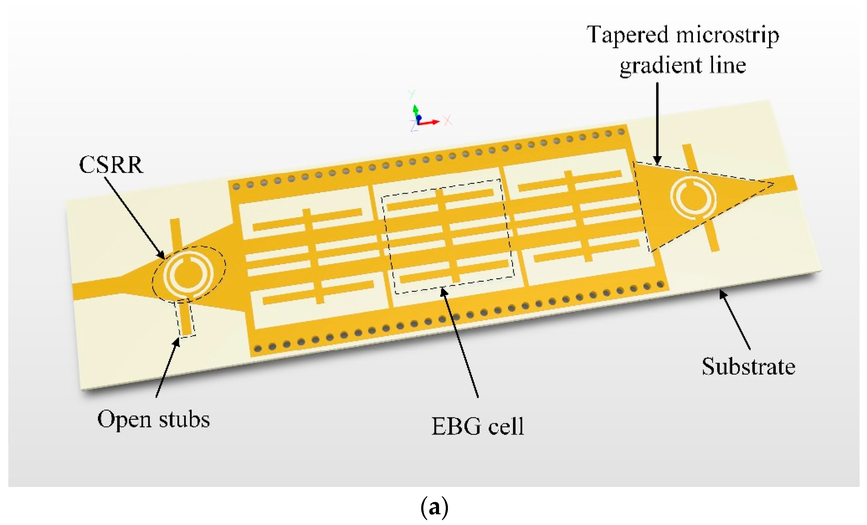
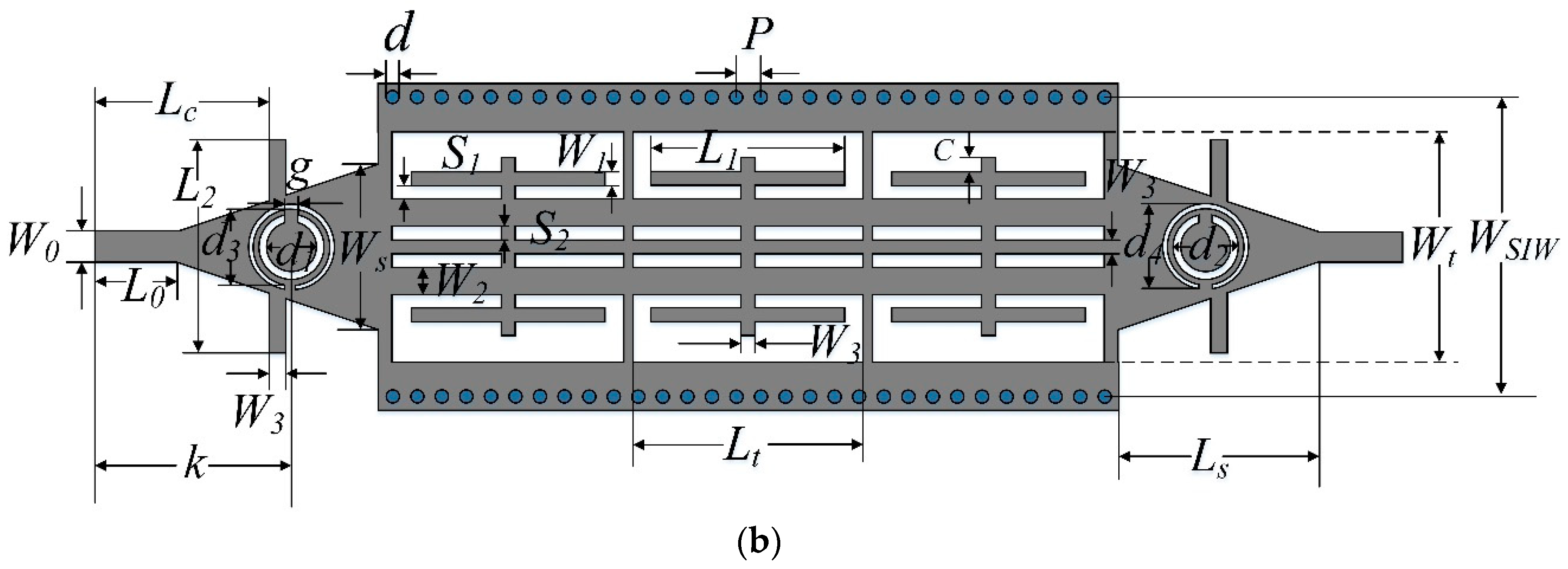
Figure 1a shows the three-dimensional (3D) geometry of the proposed wideband SIW BPF, while the physical parameters are depicted in
Figure 1b. The filter is directly excited by two 50-ohm microstrip feed lines, which are connected to the SIW by two tapered gradient lines. The smooth transition can convert the quasi transverse electric and magnetic field (TEM) mode transmitted in microstriplin into a waveguide mode to ensure a field matching between microstrip and SIW. Three periodically arranged and two identical complementary split ring resonators (CSRRs) are etched on the surface of the SIW and tapered gradient lines, respectively. The ground is covered completely by a metal, which is not be shown in
Figure 1. The dielectric substrate used in the design is a Rogers 4350 B which has a relative dielectric constant
, a loss tangent
, and its thickness is set to 0.508 mm.
The SIW, as a most basic element in the proposed BPF, is a kind of special waveguide loaded by a dielectric substrate. It has similar field distribution and transmission characteristics with traditional rectangular waveguide (RWG). If the electromagnetic waves are lower than the cutoff frequency, it will not be able to propagate in the SIW. So the SIW is used to provide a highpass characteristic in this design. Referring to the theory of RWG, the cutoff frequency of the SIW can be calculated by the following equation [
8]:
where
c is the speed of light in vacuum,
is relative dielectric constant and
is relative permeability of the used substrate,
m is the number of half waves propagating in the
x-axis,
represents the center distance between the two rows of metallized via holes,
d is the diameter of metallic vias and
p is the center spacing between adjacent via-holes.
For a lossless transmission line, the propagation constant is
. According to the transmission line theory, increasing distributed shunt capacitance C and series inductance L (i.e., high propagation constant) can make the transmission line behave with slow-wave characteristics. If the increase of C and L is discontinuous, the resonance between L and C will cause frequency-dependent reflection, forming bandstop characteristics. The adopted EBG cells consist of symmetrically arranged thin lines. Obviously, the horizontal thin lines increase the series inductance while the gap between the lines increase the shunt capacitance. When the EBG cells are connected periodically, it can be considered as a simple L-C parallel resonant circuit which can produce a stopband with a certain width. With the aid of full-wave simulator High Frequency Structure Simulator (HFSS) the frequency responses for the periodic EBG cells are shown in
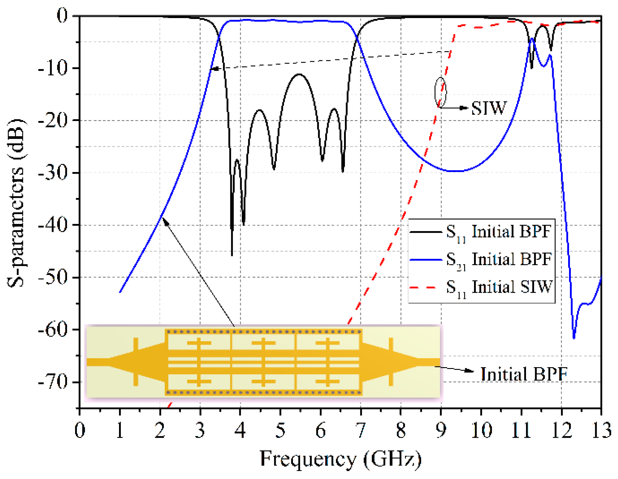
Figure 2. It can be clearly found that the periodic EBG cells exhibits a wide passband along with four transmission poles (TPs) at low frequencies. Therefore, a wide bandpass filter can be realized by combining the periodic EBG cells into the SIW. In order to independently control the lower and upper cutoff frequency, three EBG cells are periodically etched in the rectangular cutouts on the top metal surface of the SIW. The simulated frequency responses for the combination of SIW and EBG cells is presented in
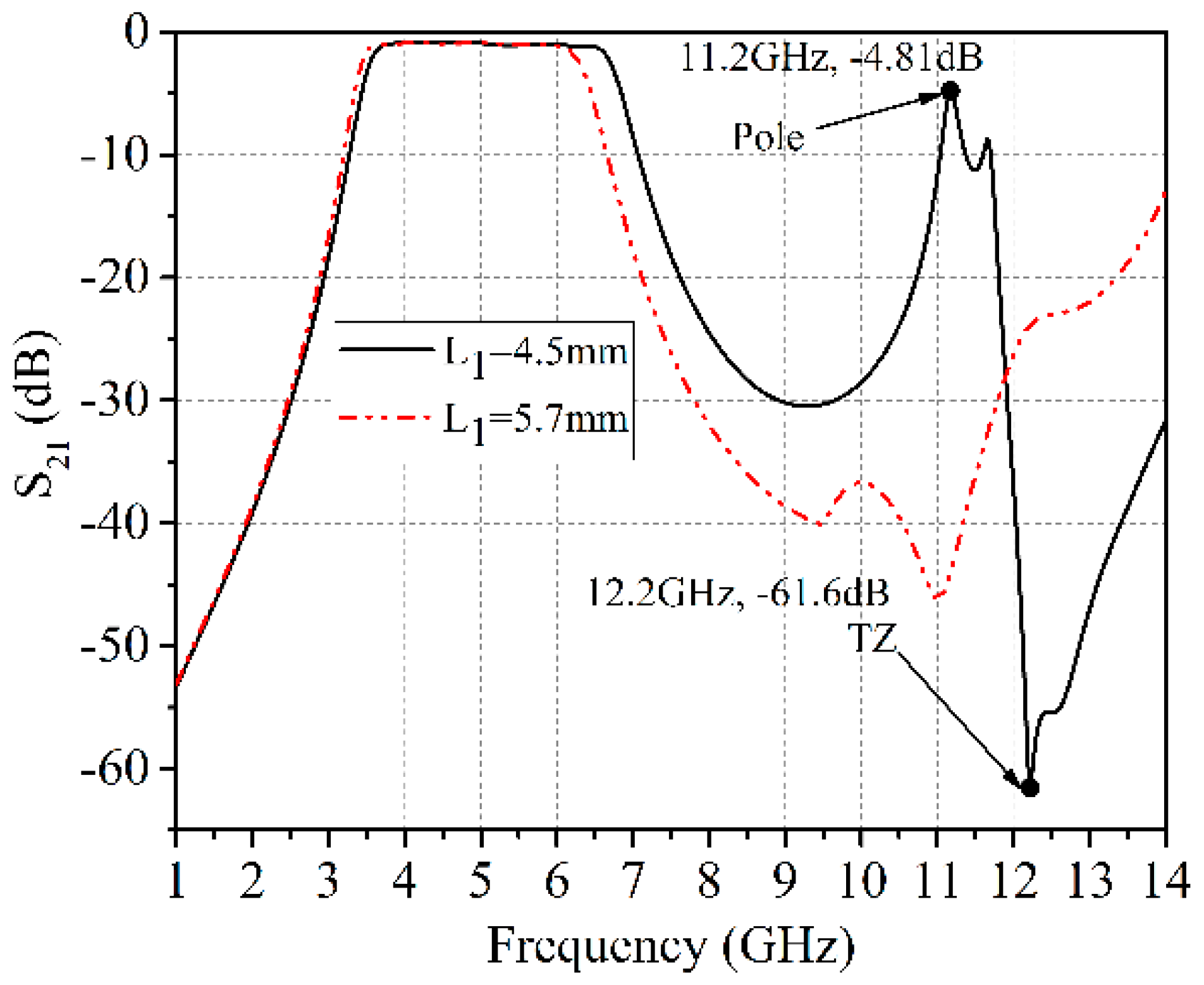
Figure 3, which is compared with the transmission coefficients of the initial SIW with the same dimensions. In fact, the proposed wideband BPF can essentially be considered as a cascade of a highpass filter and a bandstop filter. Lower and upper cutoff frequency are determined by SIW and EBG cells, respectively. The simulated results show that the lower cutoff frequency of the initial BPF is shifted from 9.36 GHz to 3.51 GHz, which is equivalent to a 62% reduction in the size of the initial SIW. Strictly speaking, the slow-wave properties of periodic EBG cells lead to a substantial miniaturization on the size of the initial BPF. Moreover, the loaded EBG cells are also very useful to manipulate the magnitude and phase of the different harmonics to obtain the improved performance. In this design, the length of
is tuned to make the higher harmonic poles disappear. A prototype of EBG-loaded SIW filter and its simulated results with different length
are shown in
Figure 4. Apparently it can be seen, when
, that a transmission pole appears at 11.2 GHz, while a transmission zero (TZ) near the spurious band is located at 12.2 GHz. Changing the length of
causes the TZ to move. In order to eliminate the undesired harmonic, the TZ has to be moved to the low frequency until it coincides with the transmission pole. As expected, when
, the transmission pole disappears and the filter has a wider stopband of up to 13.36 GHz with more than 20 dB suppression. Also it is noted that changing the length
has no obvious effect on the lower cutoff frequency. So the proposed structure has a good independence in tuning the lower and upper cutoff frequency.
For this design, finding an effective way to improve the out-of-band selectivity of the proposed filter is critical. It is well known that introducing some new frequency transmission zeros (TZs) near the passband is a good choice to obtain a better selectivity compared with increasing the order of the filter which leads to a larger circuit size and a higher insertion loss (IL) [
9]. As studied in [
10] and [
11], due to the effects of negative permittivity near the resonant frequency, a CSRR can be viewed as electric dipoles and can be excitied by an axial electric field. From previously reported literature [
12,
13,
14], it is shown that, for the CSRR-loaded waveguide, the CSRRs can generate a stopband above the waveguide cutoff frequency. All the applications mentioned above indicate that CSRR can be used as a good candidate to improve the selectivity of the wideband BPF. With respect to the direction of wave propagation, a pair of identical circular CSRRs are etched on the linearly tapered microstrip gradient lines of the input and output ports in this design as in
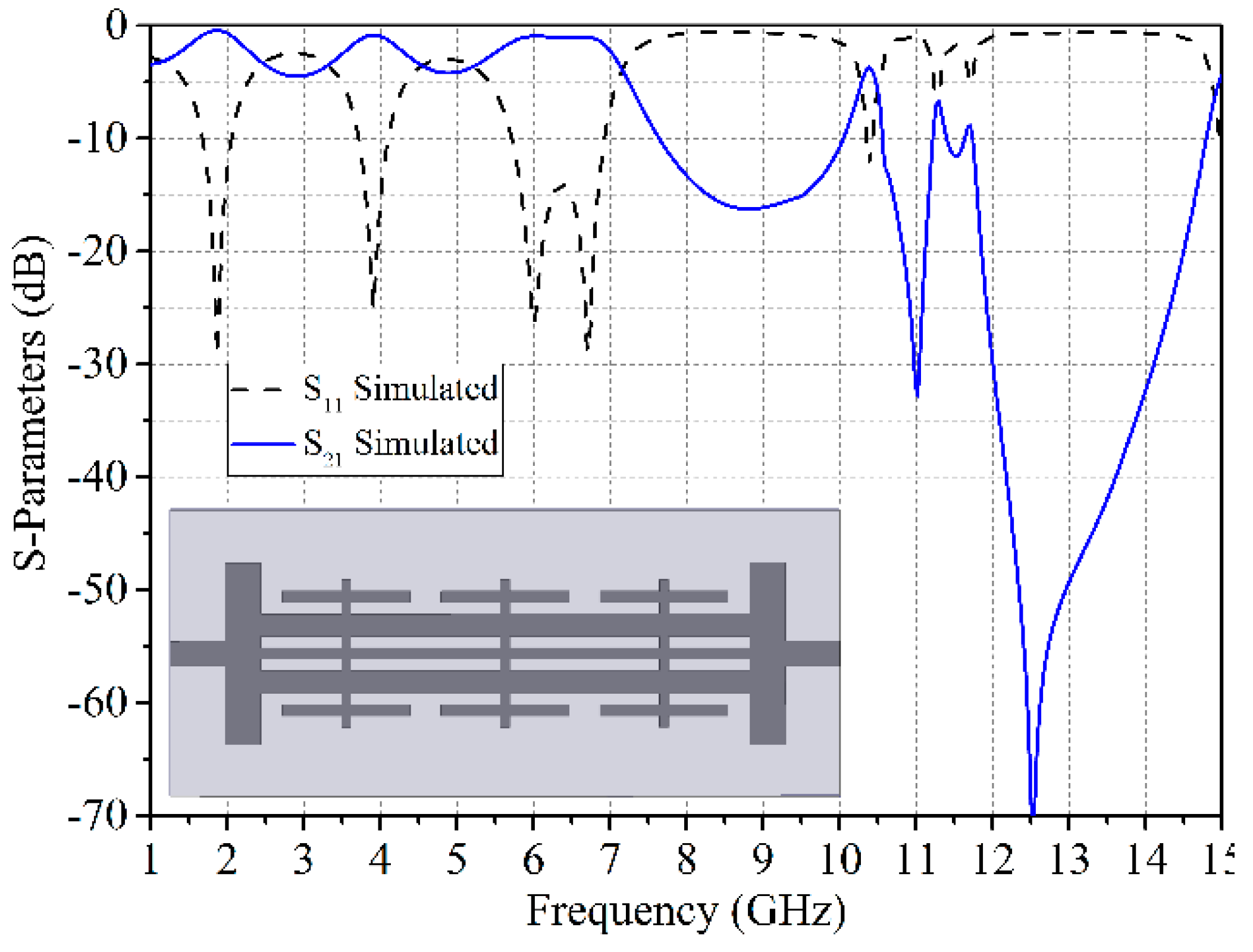
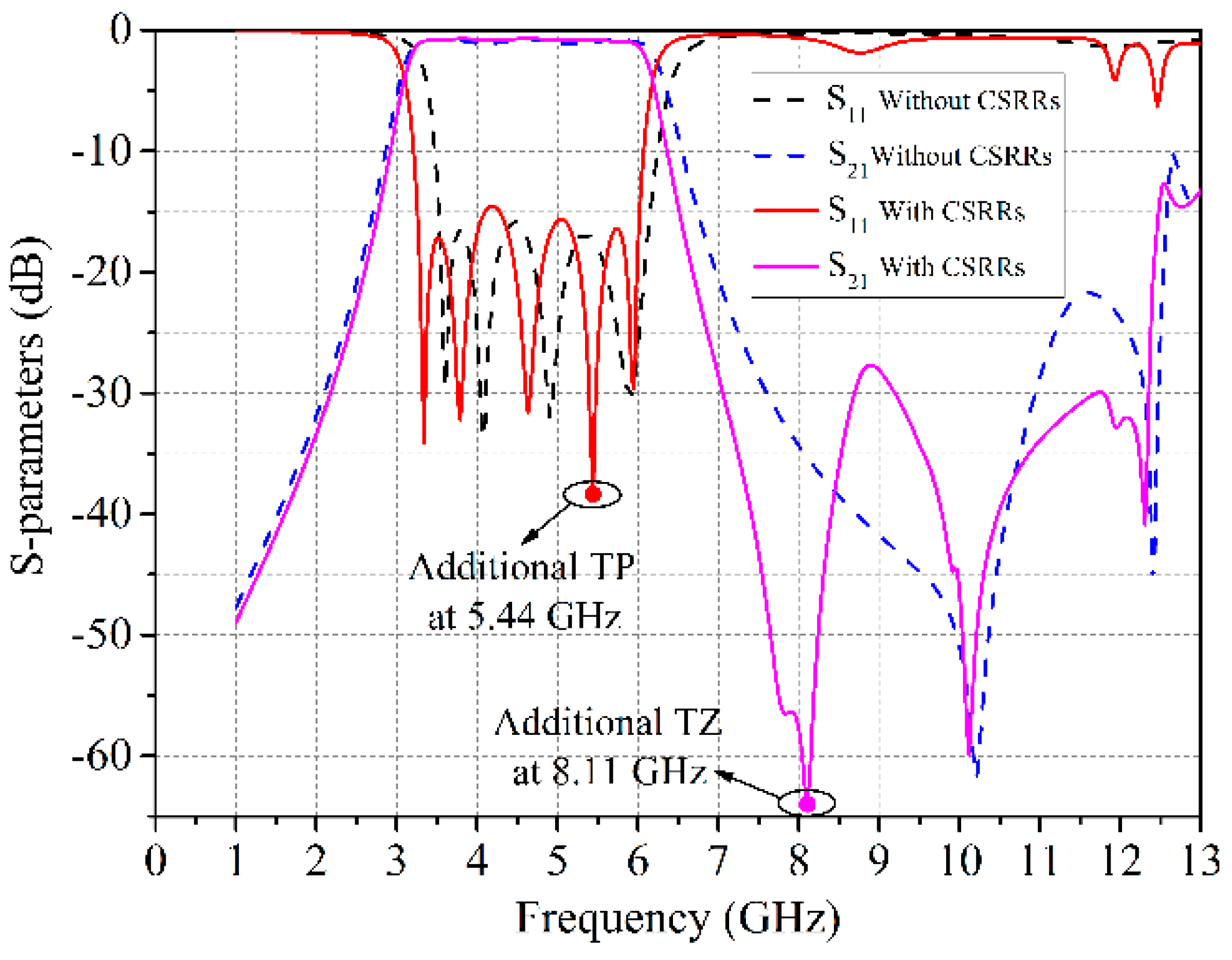
Figure 1, so that they can produce a transmission zero near the upper stopband. To take into account the passband and stopband in a balanced way, the finial geometrical parameters and the comparison of simulated frequency response results of the SIW BPF with and without the CSRRs are depicted in
Figure 5. This shows that an additional transmission zero at 8.11 GHz with −65 dB attenuation level is created by CSRRs, which leads to a steep upper side transition and greatly improves the selectivity of the wideband SIW BPF. In addition, the introduced CSRRs can also add a new transmission pole at 5.44 GHz, which improves the transmission characteristics of high frequency in the passband of the BPF.
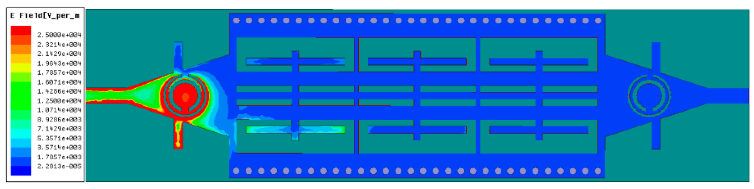
To better clarify the principle of CSRR generating TZ, the electric field magnitude distribution of the SIW BPF at 8.11 GHz is depicted in
Figure 6. As can be seen from the figure, the strong electric field distribution is mainly concentrated between the metal strip between the two slots and central conductive block of the CSRR at the input port. The electromagnetic wave with a frequency of 8.11 GHz cannot propagate to the output port, resulting in a transmission zero.
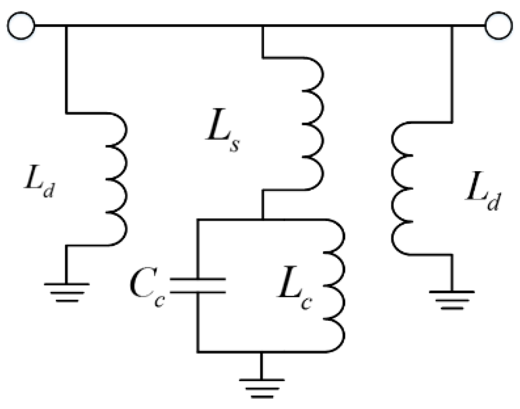
Figure 7 presents an equivalent circuit for the CSRRs-loaded SIW. In this lumped-element circuit model, the losses caused by the dielectric substrate is ignored. The SIW can be regarded as a common two-transmission line loaded with two rows of short-circuited vias which can be modeled as the inductance
. The CSRR is modeled by means of the shunt-connected resonant tank formed by the inductance
and the capacitance
.
represents the inductive connection mainly through the split of the outer ring between the tapered microstrip gradient lines and the ring resonators [
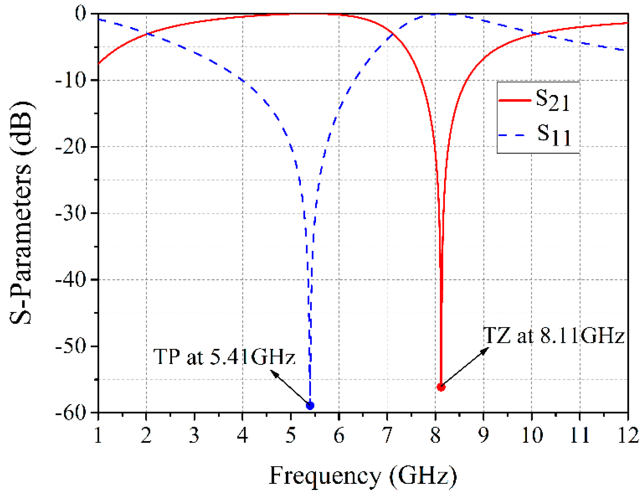
8]. In advance, the characteristics of the equivalent circuit for CSRR is analyzed using electronic design automation (EDA) software ADS (2016.01, Keysight Technologies, Santa Rosa, United States, 2015). Simulated results of the equivalent circuit are presented in
Figure 8. The reflection coefficient S
11 and the transmission coefficient S
21 are represented by the blue dashed line and red solid line, respectively. It is clearly seen that the equivalent circuit can generate a TZ and a TP, which are consistent with the results of the BPF with CSRRs simulated by HFSS. According to knowledge of microwave circuits, the equivalent circuit for the CSRRs-loaded SIW gives a transmission zero frequency at
The transmission pole frequency can be obtained as follows:
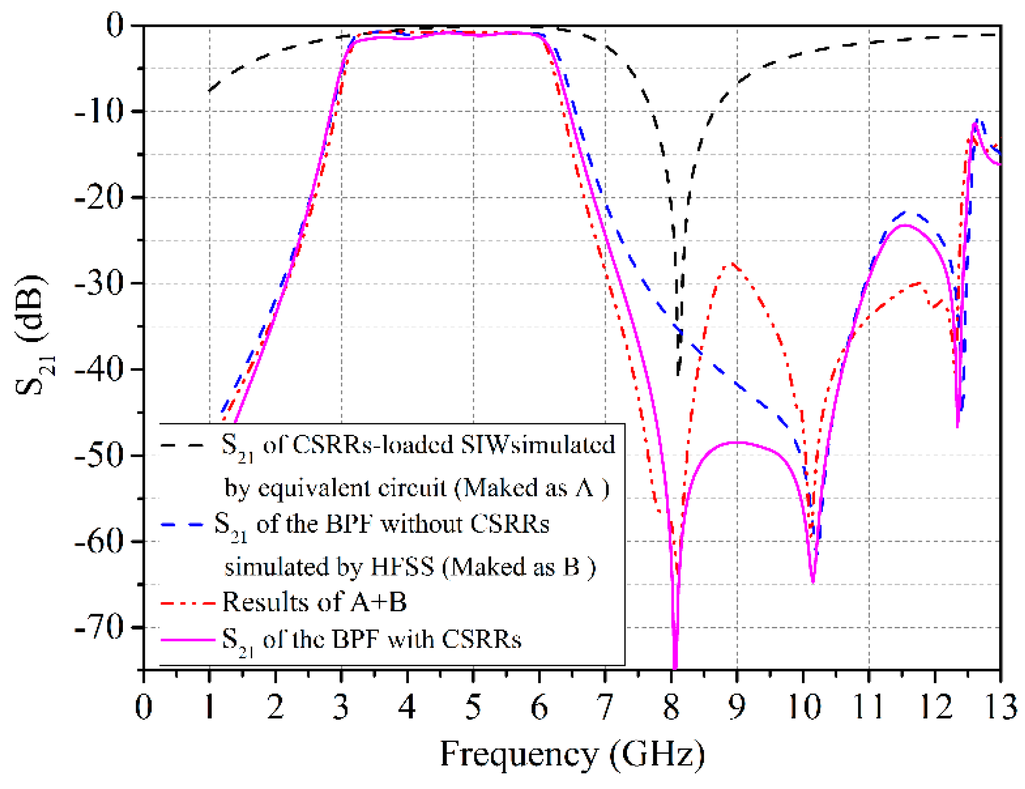
In order to prove the validity of the frequency response, which is generated by the equivalent circuit model, an extensive comparison including both the result simulated by equivalent circuit model (marked as A), the transmission coefficient S
21 of the BPF without CSRRs (marked as B) and the sum of A and B is presented in
Figure 9, which is compared with the simulated S
21 of the BPF with CSRRs. It is easy to find that the curve of A + B can fit the simulated S
21 of the BPF with CSRRs, which verifies our proposed equivalent circuit model.
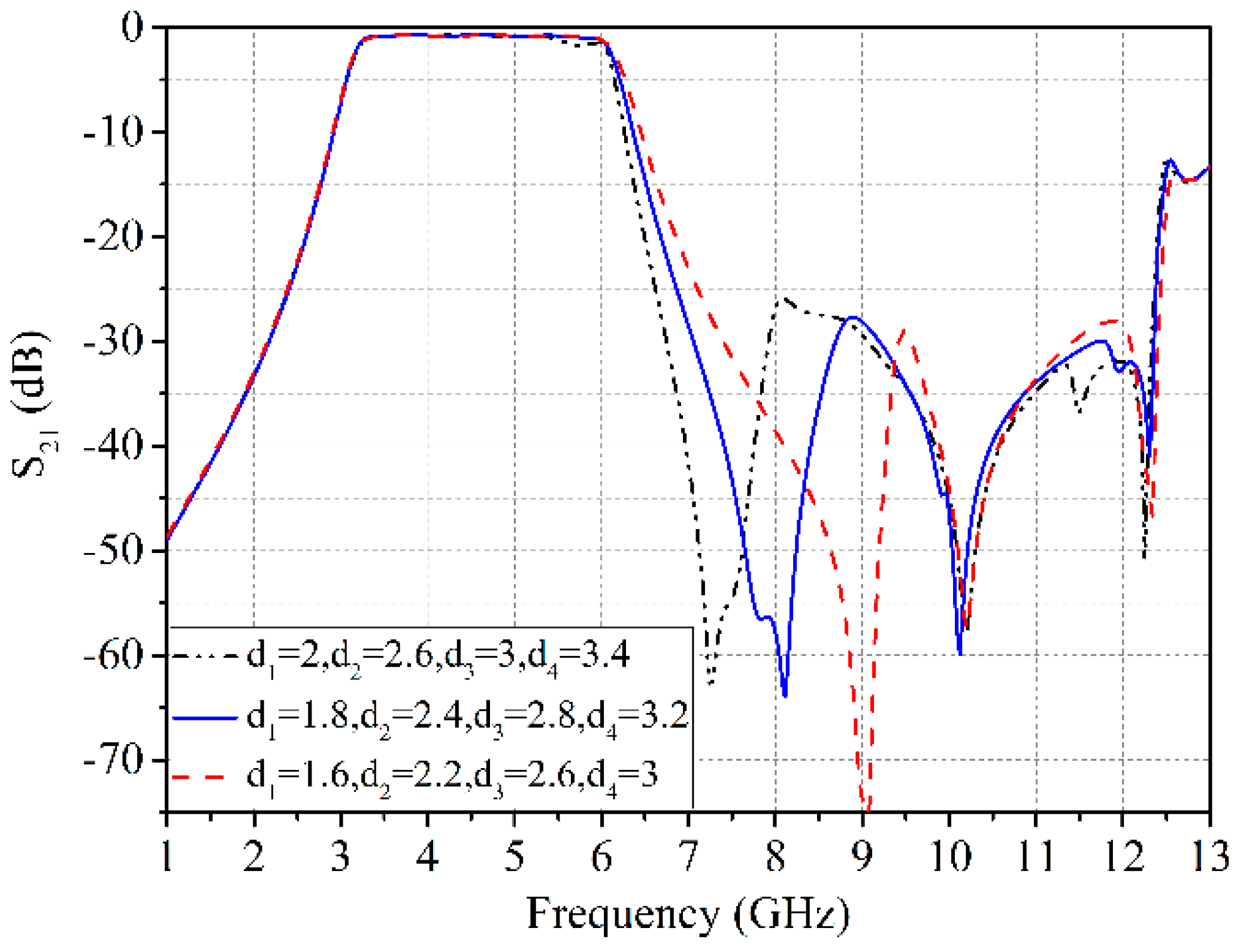
It should be noted that the additional TZ near the passband is mainly determined by the size of the CSRRs and it can be controlled independently. Changing the dimensions of the CSRRs and the different simulated frequency responses from full-wave simulator HFSS are shown in
Figure 10 Obviously, it can be confirmed that the frequency of the additional TZ can be controlled individually by appropriately adjusting the size of the CSRRs, and the change in the dimensions of the CSRRs hardly affect the transmission characteristics at other frequencies of the proposed filter.
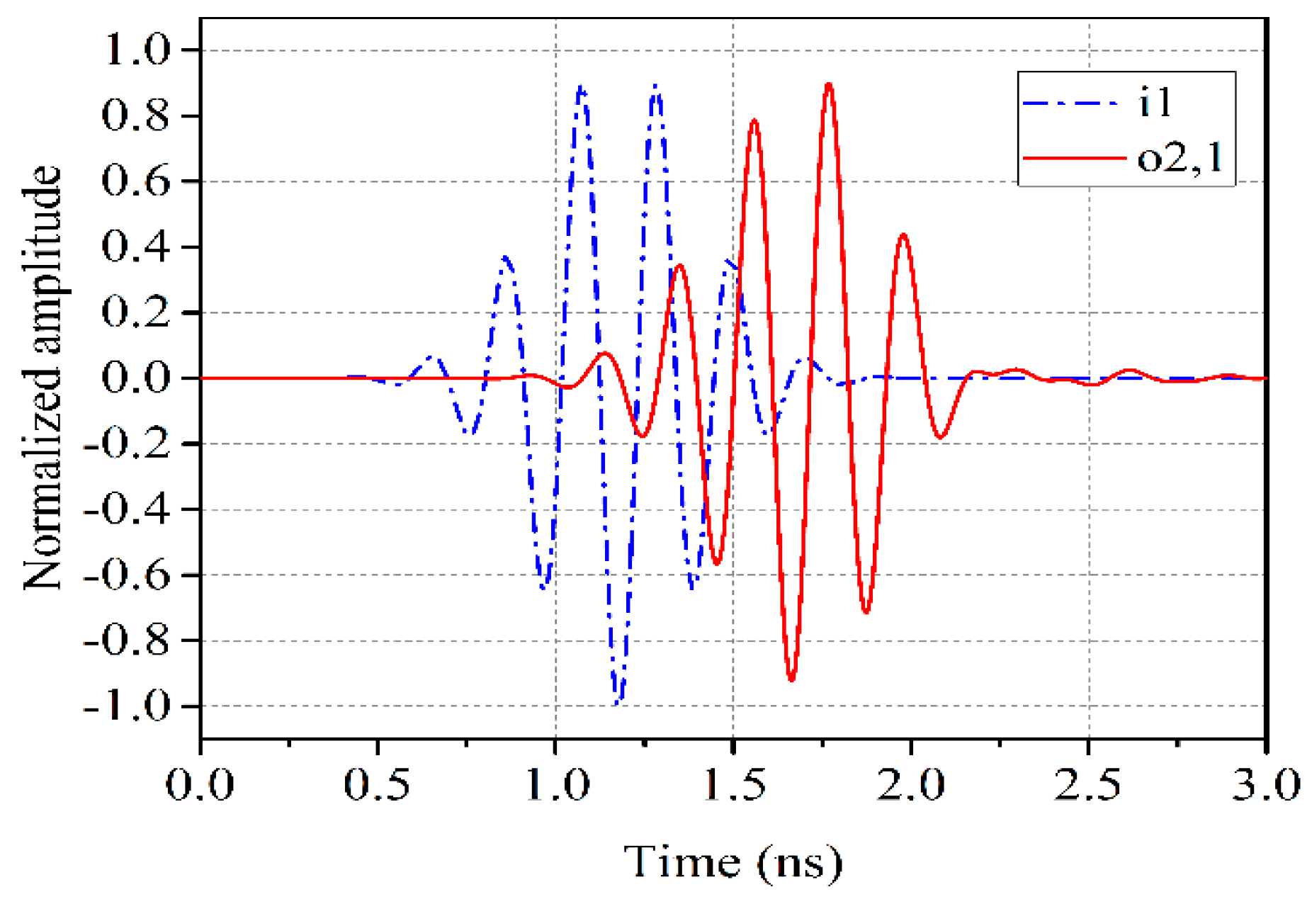
In wideband wireless communication applications, the filter is required to have a good signal fidelity capability, which cannot be obtained from its frequency-domain analysis. So an investigation of the filter time-domain behavior has to be performed. With the help of 3D electromagnetic simulator CST (2016.00, Computer Simulation Technology GmbH, Dumstadt, Germany, 2015), the filter is excited by a Gaussian pulse with a frequency of 3.16 GHz to 6.18 GHz. The as-simulated filter impulse response is plotted in
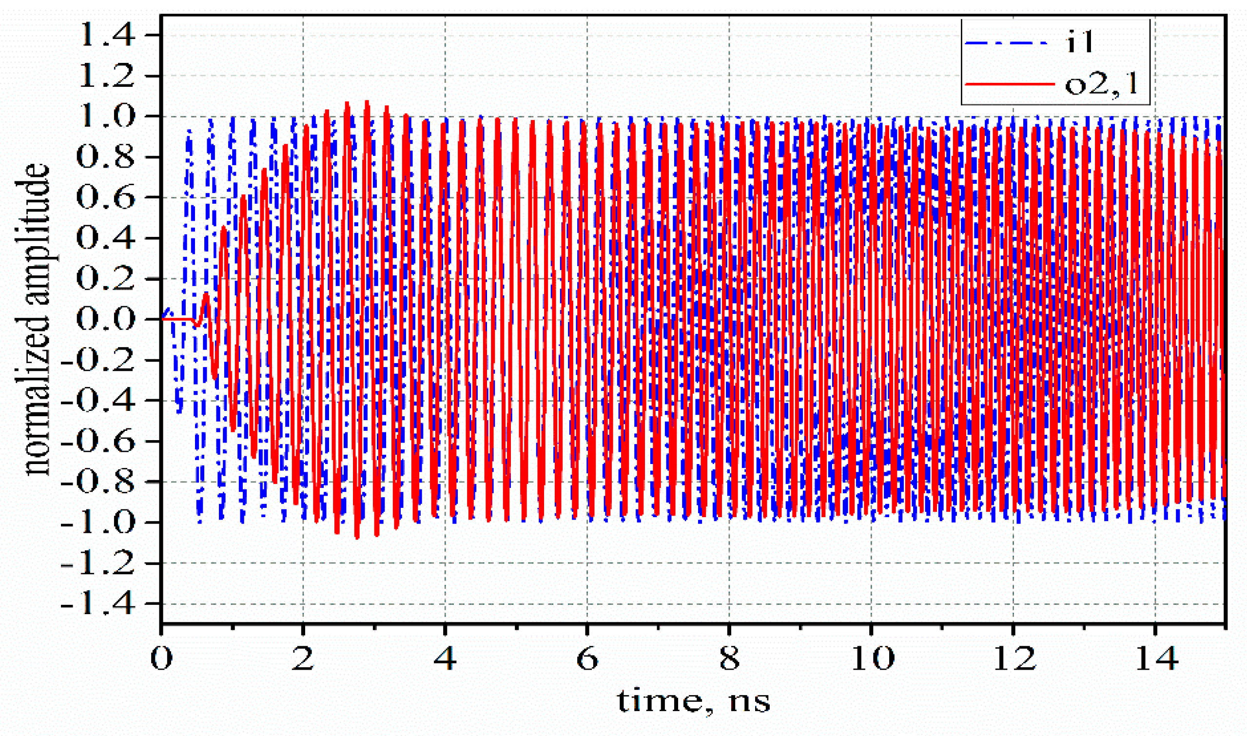
Figure 11. The Gaussian pulse is transmitted through the proposed BPF with only a delay in time, and there is hardly any change in its shape. As a verification, a sine step signal that varies from 3.16 GHz to 6.18 GHz is used to excite the filter, the response curve is shown
Figure 12. The same conclusion can be obtained. Hence, the filter has a perfect signal fidelity and a good time-domain behavior.
3. Measured Results and Discussion
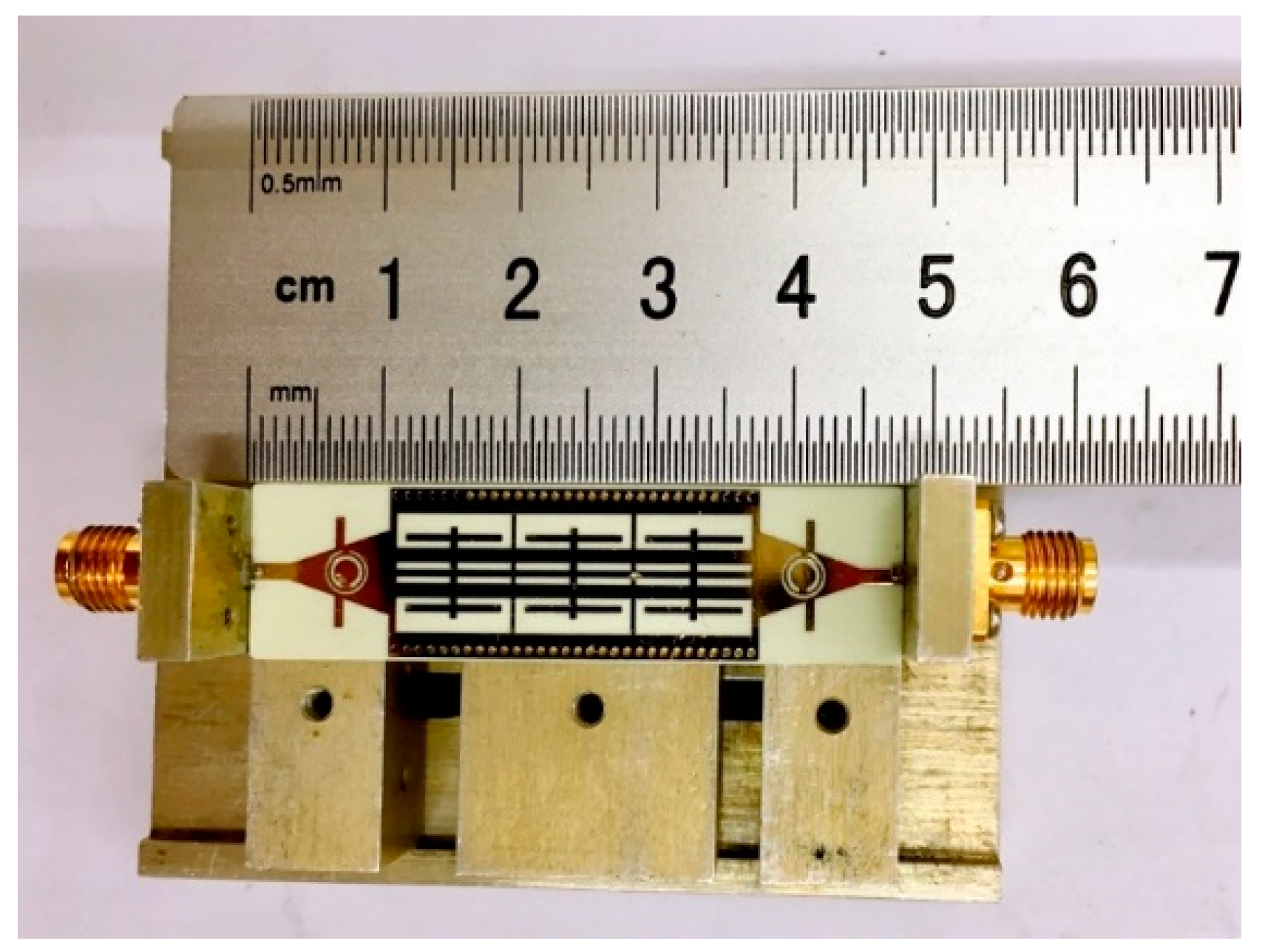
A compact wideband SIW BPF with wide stopband and high selectivity is designed and fabricated on a 0.508 mm-thick Rogers 4350 B substrate (
,
) using a standard single-side printed circuit board (PCB) process. Its photograph and the test fixture with flange joints are given in
Figure 13. The total circuit dimension excluding two 3 mm feeding lines is
, corresponding to
, where
is the guided wavelength in the substrate at center frequency of 4.67 GHz. To validate the above design approach, the fabricated BPF is measured on a vector network analyzer Agilent N5230 (Agilent Technologies, California, U.S.) series.
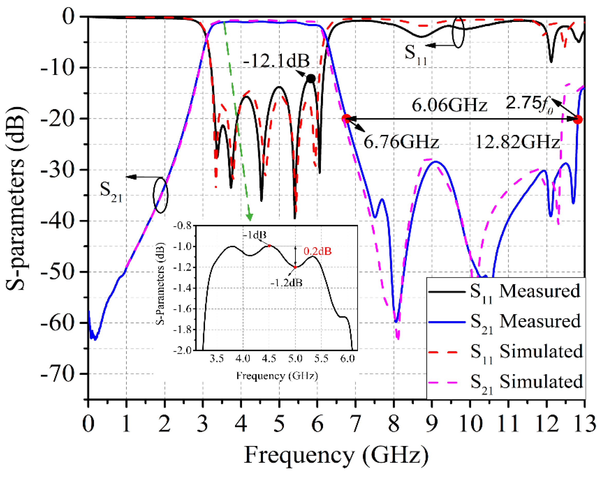
Figure 14 shows the simulated (dashed line) and measured (solid line) results. There are some slight differences between the measured and the simulated results due to machining errors and imperfect soldering processes. The measured 3 dB passband is from 3.16 GHz to 6.18 GHz with a fractional bandwidth of 64.7%. The measured in-band return loss is larger than 12.1 dB, while the minimum insertion loss is 1.0 dB. The in-band fluctuation as observed in the inset of
Figure 14 is less than 0.2 dB. It is worth mentioning that the measured S-parameters include two vertical transitions and sub-miniature-A (SMA) connectors welded on two ends of the designed BPF for connecting input/output ports. Hence, the minimum insertion loss of the filter is definitely lower than 1dB. Four transition zeroes are located at 8.05 GHz, 10.53 GHz, 12.12 GHz and 12.7 GHz, respectively, which improve the selectivity and also preserve a good upper stopband performance with attenuation level higher than 20 dB from 6.76 GHz to 12.82 GHz or 2.75
.
Table 1 depicts a comparison among the proposed BPF and some published BPFs with SIW structure. It is important to note that the parameter BW
20dB/BW
3dB represents the quality of selectivity. The smaller the value of BW
20dB/BW
3dB, the better the selectivity. As shown in
Table 1, the proposed SIW BPF exhibits better performance, including greater fractional bandwidth, better frequency selectivity, wider stopband, lower insertion loss, and smaller size. All in all, the filter proposed in this paper outperforms the quoted filters.


