Article

IoToF: A Long-Reach Fully Passive Low-Rate Upstream PHY for IoT over Fiber

1
Telecommunications Laboratory LABTEL, Electrical Engineering Department, Federal University of Espírito Santo, 29075-910 Espírito Santo, Brazil
2
Department of Physics and I3N, University of Aveiro, Campus Universitário de Santiago, 3810-193 Aveiro, Portugal
3
Instituto de Telecomunicações, Campus Universitário de Santiago, 3810-193 Aveiro, Portugal
4
Department of Electrical and Computer Engineering, Instituto Superior Técnico, University of Lisbon, 1049-001 Lisbon, Portugal
5
Department of Electronics, Telecommunications and Informatics, University of Aveiro, Campus Universitário de Santiago, 3810-193 Aveiro, Portugal
*
Authors to whom correspondence should be addressed.
Electronics 2019, 8(3), 359; https://doi.org/10.3390/electronics8030359
Submission received: 13 February 2019 / Revised: 22 March 2019 / Accepted: 22 March 2019 / Published: 25 March 2019

Abstract

:
Internet of things (IoT) devices heavily rely on wireless connectivity. There are intrinsic overlooked limitations such as reach, availability, security and safety vulnerabilities closely associated with wireless solutions. Wired connectivity is the alternative to tackle those issues, and optical fibers directly connecting IoT devices could provide them unique features such as huge bandwidth, long reach, signal integrity and high security grade for the transmitted information. Nevertheless, it can be prohibitive for IoT devices which are power hungry and have costly electrical-to-optical conversions. In this paper, first, a niche is identified for IoT over fiber (IoToF) based on fully passive optical solutions for long reach upstream of low data rate optical connectivity over dark fibers. Then, we proposed, implemented and characterized a prototype physical connectivity (PHY) based on fiber Bragg grating (FBG) low-cost acousto-optic modulation at IoT devices and respective optical edge-filtering as wavelength discriminator at the receiver. Finally, we performed an experimental demonstration of upstream data communication based on simple M-ary frequency-shift keying (FSK), with baud rate of 300 bps transmitted over 30 km range. In terms of data rate and reach for niche applications, IoToF can outperform traditional wireless technologies, such as Sigfox or LoRa. IoToF will enable monitoring urban areas with scarce and polluted spectrum, industrial areas requiring intrinsic safety, and upstreaming data from IoT devices in remote locations with unfavorable wireless propagation but with dark fibers available.

1. Introduction

The concept of the internet of things (IoT) is rapidly expanding its reach involving applications in different fields such as domotics, industry, healthcare, and smart cities [1,2,3,4]. The original IoT concept appeared more than three decades ago, being used to combine people, processes and devices with communication technology to remotely exchange data for processing and management [5]. The term IoT was originally attributed to Kevin Ashton in 1999. In his definition, “internet” refers to the global system of interconnected computer networks using the standard internet protocol suite (TCP/IP), which are linked by a broad array of electronic, wireless and optical networking technologies. The “things” term refers to real objects and living entities in the physical or material world. IoT can be considered as a global network, which allows the communication between human-to-human, human-to-things and things-to-things, each element with a unique identity [6]. Therefore, ubiquitous connectivity is an important challenge posed by IoT to communication infrastructures.
An unexplored IoT connectivity scenario involves wired networks based on optical fiber directly attached to IoT devices. This may be necessary to go around intrinsic wireless networks limitations. Passive optical networks (PONs) could be a candidate solution, offering both extended reach and high bit rates. But for some IoT devices, the power hungry [7] and costly electrical-to-optical conversions could be a severe limitation, and such physical connectivity (PHY) may be an overkill solution for most of IoT typical data rate requirements. Therefore, there is a gap to be bridged for low data-rate transported over long distances using fully passive optical solutions.
To the best of our knowledge, this is the first time that a fully passive optical architecture is proposed and demonstrated, where digital data modulation passively modulated over an optical signal, which is transmitted over ranges tens of kilometers, outperforming low data-rate long-reach wireless technologies such as LoRa and SigFox. In the current work, we proposed a cost-effective modulation scheme composed by a fiber Bragg grating (FBG) mechanically driven by an acoustic signal containing the IoT information. FBGs have been broadly used in the sensing field such as overhead transmission line wire sag monitoring [8], liquid level monitoring [9], temperature [10], strain [11], and acceleration [12]. In this approach, we focused on the use of the FBG not as a sensor but rather as a modulator, which allows encoding the IoT device’s information directly into wavelength shifting. The Internet of things over fiber (IoToF) proposal does not intend to replace the current wireless technologies nor conventional solutions for optical communications. The main idea of IoToF is to overcome the different limitations of current wireless and optical technologies for serving IoT. IoToF reinforces the concept of ubiquitous IoT by enabling such concept to reach, for instance, regions with very unfavorable wireless propagation environments and extremely limited energy availability.
The remainder of the paper is divided as follows. Section 2 discusses IoT connectivity, requirements for IoToF, concept and operation principle of IoToF architecture, and the implementation and characterization of a FBG-based IoToF prototype. In Section 3 the experimental results are reported. Finally, conclusions are drawn in Section 4.

2. Materials and Methods

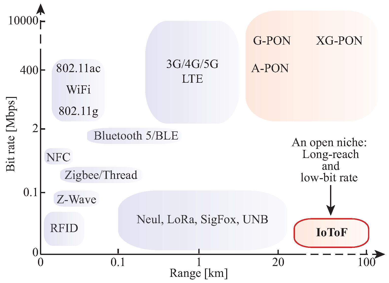
2.1. IoT Connectivity

Several wireless standards for IoT applications have been proposed during the last two decades [13]. For local and personal area networks, the Wi-Fi, Bluetooth low energy (BLE), Zigbee and thread standards [14], Z-wave protocol [15], radio-frequency identification (RFID) [16,17], and near field communication (NFC) [18] can be highlighted. For wide areas, the long-term evolution (LTE) [19], Neul’s ultra narrow-band (UNB), Sigfox and LoRa are broadly used [14,20].
Wireless is ‘de facto’ the connectivity technology for IoT. In part, this is because of its agility and scalability. There is virtually no cost and no waiting time for setting up and tearing down connectivity facilities for IoT elements. However, there are well known issues with wireless communications, especially for wide areas, which are only partially addressed by current technologies. Spectrum usage, propagation environments and topography are relevant factors that may severely degrade a signal’s quality. In addition, weather conditions and multipath fading effects may induce signal-to-noise fluctuations that might be incompatible with reliability requirements for providing connectivity for critical IoT applications. The broadcasting nature of wireless connectivity has evidently fundamental privacy and security vulnerabilities; and they may carry more weight than other aspects when deciding the right IoT connectivity solution. Finally, time delay is another drawback for wireless communication systems. Mazur et al. proposed a reconfigurable network model to find a trade-off between the security, performance and time delays for wireless network sensors. A developed smart grid model is used to identify the optimal positions of direct connections minimizing transmission delay, energy consumption and financial cost of sensors’ arrangement [21].

2.2. The Role of Optical Connectivity in IoT

An alternative to tackle IoT connectivity issues is to move, at least, a part of the IoT devices to wired links. In this case, optical fiber is a natural candidate, especially for IoT covering wide geographical areas. Fiber optics offer a huge bandwidth with very low attenuation, typically 0.2 dB/km for standard single mode fiber (SMF), allowing throughput and reach figures that are orders of magnitude superior to what wireless systems offer to IoT. The optical equivalent to frequency division multiplexing, used in wireless systems to create several channels, is the wavelength division multiplexing (WDM) in optical communications systems. This dramatically increases capacity (data rate) of a single fiber by using different wavelengths for different carriers [22].
Optical fibers are usually thought of as big pipes for transporting aggregated IoT traffic beyond IoT gateways [23]. The discussion here focuses on providing optical connectivity to IoT devices themselves. We call this modality the IoToF to express this direct physical connectivity (PHY) and to differentiate the other use of optical fibers in IoT. Fibers directly at IoT devices may initially seem an overkill solution, but this would be viable and applicable when availability, reliability, security and other limiting factors are handicapping physical connectivity solutions based on wireless and other wired technologies. Optical cables are easily found in metropolitan areas, industrial plants as well as alongside highways and remote rural roads, power transmission lines, and railways. Therefore, dark fibers availability (i.e., spare fibers in already deployed optical cables) may be key for IoT; not only for its unexploited broadband capability but also for providing very basic connectivity as proposed here by the IoToF concept.
For instance, IoToF can find niches in monitoring urban areas with crowded and/or polluted spectrum, power lines structure and environment monitoring, collecting data in gas and oil industry, and IoT wildfire monitoring in extremely remote locations, where dense forests in hilly regions may create very unfavorable wireless propagation environments. IoToF may be thought as an alternative to reduce both cost and latency in replacing the upstream side of satellite-based Internet of remote things (IoRT) [24].
Before exploiting optical fibers in this new context, there are fundamental mismatches between IoT requirements and the enablers factors from optical fiber communication systems to be addressed. In order to make IoToF viable, an alternative approach for optical communications should be sought. Note that a similar challenge has been faced before in access networks employing optical communications. Fiber strands were only able to physically reach the premises of individual domestic customers after the concept of passive optical networks (PON) has been developed to ease capital and operational expenses (CAPEX and OPEX, respectively) of optical solutions [25].

2.3. Requirements for IoT over Fiber (IoToF)

We are aiming to develop a niche solution to fill gaps from an IoT arena dominated by extremely low-cost and widespread wireless solutions. Therefore, one of the main challenges in IoToF systems are CAPEX and OPEX. But, it should be noted that optical solutions are costly because they involves electrical-to-optical (E/O) and optical-to-electrical (O/E) interfaces—and not for the optical fiber itself. In addition, such interfaces are usually power hungry circuits, whereas optical fibers are electrically passive elements. Energy is certainly a major constraint for IoT solutions and, therefore, E/O and O/E conversions need to be addressed in IoToF PHY architectures before benefiting from long-reach with reliability, privacy and other appealing features from optical fibers compared to wireless ones.
Table 1 highlights some matching factors between conventional optical communication connectivity and desired IoToF PHY architectures. Data throughput required by individual IoT devices is usually several orders of magnitude below the figures that optical interfaces can offer. The long reach and reliability from optical fibers is what IoToF seeks to bring to the IoT ecosystem. Installation and maintenance in conventional optical systems is costly, time-consuming, and expensive at E/O and O/E interfaces involving specialized splicing equipment and connectors, whereas the wireless counterpart operation is virtually effortless and costless. Therefore, IoToF should aim at extremely simple operations. In addition, conventional optical communication E/O and O/E are power consuming due to the need of biasing and cooling circuitry whereas IoToF would aim, if possible, at optical passive solutions at IoT devices. Spectral efficiency is not a major concern in optical systems as seen in the widespread use of on-off keying and direct detection to reduce cost [22]. In contrast, the extremely low-cost requirement from the IoT systems will push for IoToF solutions with limited end-to-end bandwidth, where spectral efficiency becomes an issue to be addressed.
In order to put IoToF into the IoT wireless connectivity context, we focus on two relevant parameters in Figure 1: throughput and reach. Higher-frequency bands offer more channels and bandwidth, allowing more data throughput, nevertheless lower transmission distance is achieved. Lower-frequency radio waves are less perturbed during the propagation than higher-frequency waves, reaching a higher operation range, with a reduced data throughput [14]. IoToF requirements should aim at ranges beyond conventional wireless solutions, without compromising minimal throughputs achieved. It is expected for IoToF, in Figure 1, to exceed a fundamental wireless limit: Radio horizon [27]. It is the furthest reach imposed by the earth’s curvature light-of-sight propagation, including atmosphere refraction effects [28]. The Radio horizon for a 30 m height gateway antenna and an end station at 1 m is around 20 km [27], which is within LoRa’s and SigFox’s experimentally reported ranges. Coincidently, this is also Gigabit PON (G-PON)’s maximum non extended reach [25,29]. 20 km makes up an important optical and wireless landmark for IoToF to surpass and find its own niche.
This paper puts forward the IoToF concept, suggesting a simple architecture and implements a prototype to demonstrate its feasibility. In Section 2.4, we argue that FBGs can be a key element for implementing solution to meet IoToF PHY requirements listed in Table 1. FBG can be used to inexpensively modulate information coming from IoT devices directly onto the optical signal in a passive way, enabling upstream transmissions over long distances satisfying the requirements outlined in Figure 1. In addition, different IoT devices can physically share a single optical fiber using FBGs tuned on different wavelengths. This provides a point-to-point (i.e., non-shared) upstream connectivity with a gateway exploiting the fiber bandwidth with wavelength division multiplexing to improve availability and privacy over IoToF for each IoT device.

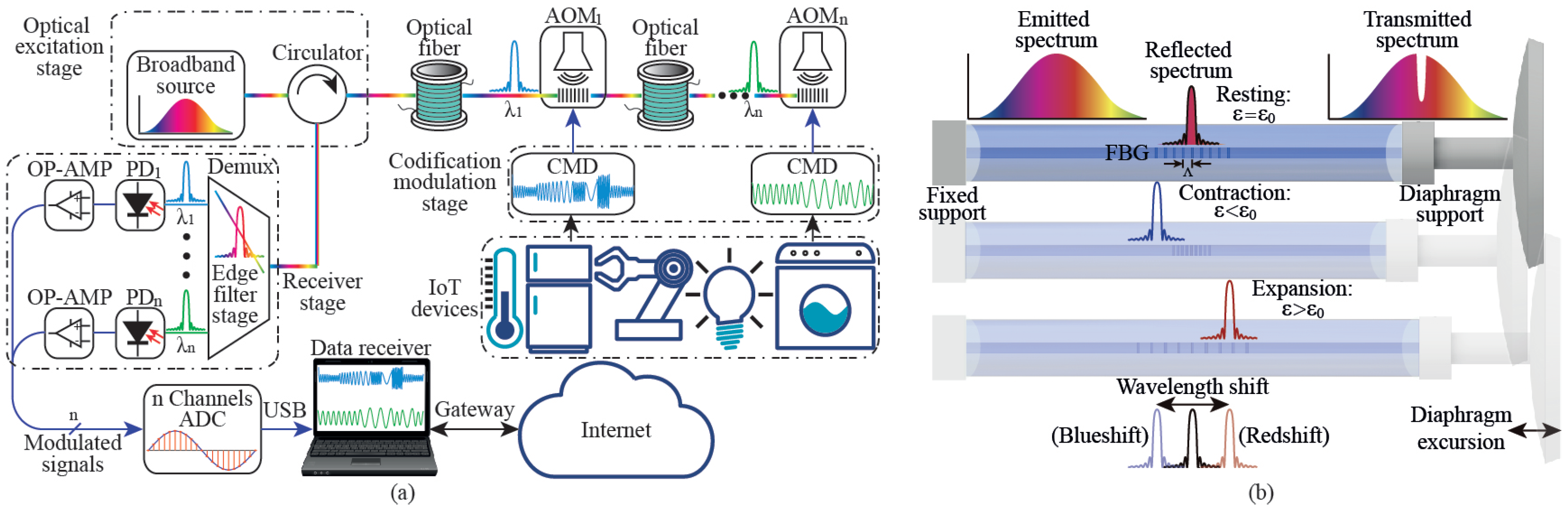
2.4. FBG-Based IoToF: A Fully Passive Optical Architecture

A FBG-based IoToF concept is presented in Figure 2a, which is composed of five main blocks. Starting from IoT devices, their information undergoes codification-modulation device (CMD) before reaching the acousto-optical modulators (AOMs) elements, which are composed of FBGs mechanically driven by an acoustic signal containing the IoT information. In other words, the CMD receives the information (analog or digital format) from the IoT devices and codifies this information into analog signals which fed the AOM. The data of IoT devices is translated from the electrical domain to the optical domain into wavelength codification. Provided that FBG are completely passive elements, the optical excitation stage sends a broadband signal, covering all the FBG individual backscattering peaks. An optical circulator enables the use of a single fiber to send the broadband signal, and simultaneously, collect the individual FBGs backscattered responses (i.e., Bragg wavelength which contends the IoT devices information) along the fiber to, in turn, feed the receiver module.
To better understand how our FBG-based AOMs work, Figure 2b illustrates a fiber grating changing its backscattered spectrum according to mechanical waves. A longitudinal movement imposes either a contraction ( ε < ε 0 ) or an expansion ( ε > ε 0 ) in the FBG when a mechanically attached transducer (e.g., buzzer or loudspeaker) is fed with an external electrical signal. Hence, launching an excitation optical broadband source in the fiber, a blueshift or redshift is observed in the Bragg wavelength of the FBG backscattered spectrum as function of the applied electric signal. Whether the transducer is not fed ( ε = ε 0 ), the Bragg wavelength shift depends mainly on temperature effects. Since the temperature variations occurs at very low frequency when compared with strain variations (which occurs from 100 Hz to 800 Hz in the current work), the temperature cross-sensitivity can be neglected or filtered by a high-pass filter [12].
In Figure 2a, the receiver stage performs the optical to electrical conversion task. Note that there are several FBG-based AOMs along the same optical fiber, being each one associated with a different Bragg wavelength ( λ 1 , λ 2 , , λ n ). A low-cost solution for optical spectrum monitoring is to employ edge-filtering [11]. A wavelength demultiplexing device is proposed here to act as such wavelength discriminator. It is necessary to guarantee that the Bragg wavelength is located in the edge of the corresponding channel from the demultiplexing element. In other words, it is possible to obtain a wavelength-to-amplitude conversion, allowing that the FBGs’ spectral shift are translated into an optical power variation, which in turn are converted into the electrical domain by the photodetectors (PD 1 , PD 2 ,…,PD n ).
Edge filtering processes can be performed with matched FBG-based filters [30], in-fiber Fabry–Perot micro-cavities [11], long period gratings [31], chirped-FBGs [32], tilted-FBGs [33], and a large length of fiber used to create the edge-filters such as Erbium doped fiber [34] or multimode fiber [35] based edge-filters. As presented by the authors in [11], the most equilibrated relation between visibility and dynamic range is achieved with the micro-cavities approach, which is also used in the current work. Since the proposed approach is based on edge-filtering, the number of AOMs is limited and pre-determined by the demultiplexer ports at the receiver stage. To optimize the bandwidth of each AOM, each CMD must integrate more than one IoT device. On the other hand, the technique of edge-filtering is vulnerable to optical power fluctuations. Therefore, parameters such as bandwidth and visibility of the filter, excursion of Bragg wavelength shift, and sensitivity of the receiver need to be into account to improve the signal to noise ratio [12].
In the electrical path of Figure 2a, signals are amplified by the operational amplifiers (OP-AMPs) in a transimpedance configuration and then acquired by a multichannel analog-to-digital converter (ADC) module to reach the data receiver. These signals are processed and demodulated in the data receiver to connect with the IoT gateway to share the information on the Internet.
The devices in Figure 2a can be also translated into PHY functional sub-layers depicted in Figure 3. First, the information layer converts information-to-electrical (I/E) pulses, which in turn undergo electrical-to-acoustic (E/A) conversion alongside an appropriate coding and modulation format to be sent through an acoustic channel. This represents the mechanical structure used to reach the acoustic-to-optical (A/O) conversion at FBGs, which only allows imprinting mechanical displacement into frequency modulation (FM). The optical channel transports the original information through long distances to finally reach the optical receiver. There, the received signal undergoes O/E conversion, which is performed directly without any intermediate optical-to-acoustic conversion, by photo-detecting amplitude modulated (AM) signals resulting from the edge-filtering FM optical signals. Finally, in the electrical domain, the signal is then digitalized with an ADC performing electrical-to-digital (E/D) followed by digital-to-information (D/I) conversion, i.e., demodulation and decision. Marks from M 1 to M 3 are inserted in Figure 3 to report piecewise characterization results from the IoToF prototype described in the next section.

2.5. IoToF Prototype Implementation

This section briefly describes constructive details of the main functional sub-layers, in Figure 3, of a proof-of-principle IoToF implementation with a single IoT device. The challenge here is to test if the requirements presented in Table 1 and in Figure 1 can be met with a simple and low-cost setup.

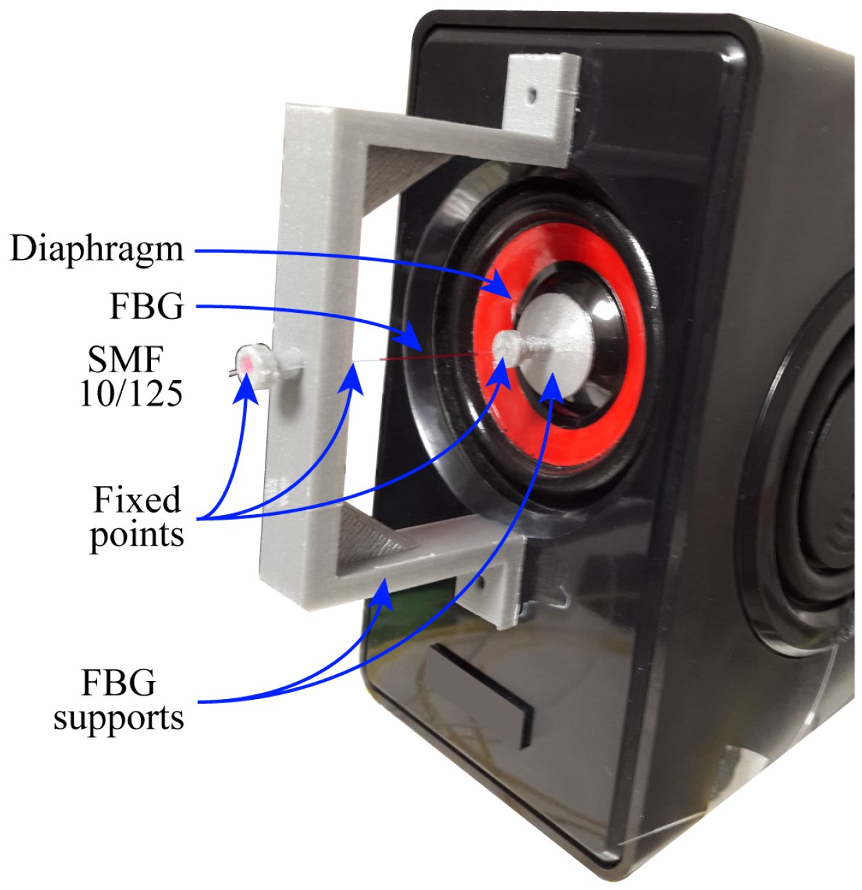
2.5.1. Acoustic-to-Optical Module

The AOM prototype depicted in Figure 4 is based on a FBG mechanically actuated by an off-the-shelf loudspeaker with 48 mm diameter membrane. As discussed before, the acousto-optical modulation was always translated into FM over a backscattered optical carrier. As presented in Figure 4, the right side of the fiber was glued on the diaphragm support, which in turn is glued over the speaker membrane. Following, the FBG was pre-stressed (strain, ε = ε 0 ) and glued on its left side to other anchorage point, after removing the fiber acrylate protection in order to improve its adhesion. The FBG was recorded with the same specification as reported in [12].

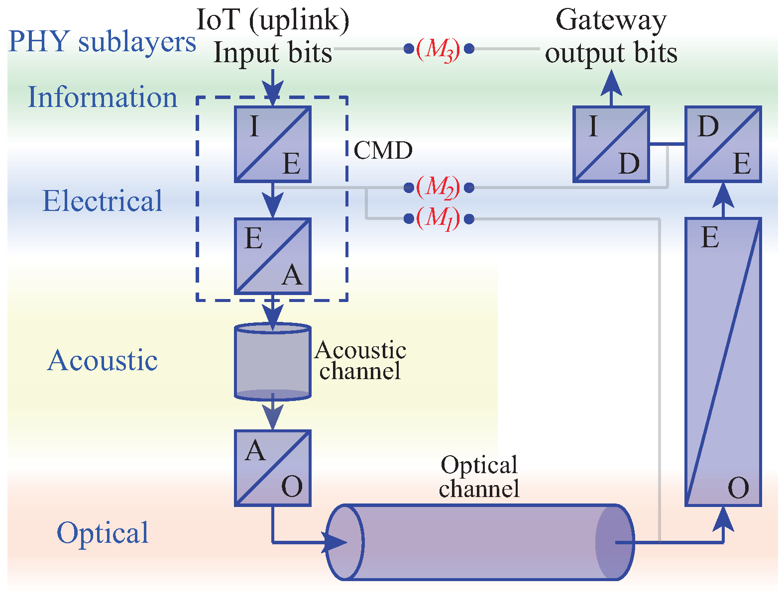
2.5.2. Electrical-to-Acoustic Module, Acoustic Channel, and Digital Modulation Strategy

Our E/A module was composed of the loudspeaker’s field coil to which the electrical signal is connected. Before reaching the A/O element (i.e., FBG) described above, there is a system (with complex dynamics) composed by an electro-magneto-mechanical system with considerable inertia, encompassing permanent magnet-field coil interactions, a diaphragm, an acoustic box structure, and a FBG supporting elements. As a result, inertia and resonances may create preferable frequency response bands. All these electro-magneto-mechanical dynamics are here considered as an acoustic channel. Its constraints will require proper line coding or modulation formats to be chosen at E/A conversion to best exploit this baseband channel, i.e., a communication channel that can transfer frequencies that are near zero.
Neither baseband amplitude on-off keying/amplitude-shift keying (OOK/ASK) nor narrow-band phase-based phase-shift keying (PSK) modulation are not supported by the E/A module. Dumping response of the whole system is considerably increased when strong amplitude changes are induced. In addition, the mechanical inertia is a handicap of this system to respond to phase changes. Among the digital scheme modulations, multiple frequency-shift keying (M-FSK) was selected to impress digital symbols onto the Bragg wavelength. M-FSK is a continuous-phase modulation which reduce the bandwidth spectral use and allows a smooth transition between bits/symbol. In addition, the FSK is a modulation scheme appropriate for channels that lack the phase stability required to perform carrier-phase estimation [36].

2.5.3. Optical-to-Electrical Module and Demodulation Strategy

There are several factors which improve the O/E conversion performance: (i) in the optical domain, the sensitivity is function of the edge filter slope inclination, and the dynamic range is function of the visibility and bandwidth of the filter; (ii) in the electrical domain, the OP-AMP bandwidth as well as the maximum ADC sample rate defines the end-to-end system bandwidth. The sensitivity is related with the ADC quantization, and for ADC with high resolution (16 bits or higher), this parameter is considerably improved. Our O/E module follows [12]. After passing the modulated signal through the transmission channel, a delayed and noisy version of the transmitted signal will be received at the demodulator (E/D module). In order to perform the demodulation (E/D) and decision processes (D/I), two different methods can be implemented. One is the phase-coherent demodulation and detection, where it is necessary to estimate the M carrier phases. This process is extremely complex and impractical for a large number of signals. The other solution neglects the carrier phase, simplifying the demodulation and detection processes. In this case, per each signal waveform, two basic correlation functions (quadrature carriers) are used, requiring 2 M correlators [36].

2.5.4. Experimental Setup and System Characterization

The implemented testbed, according to the IoToF architecture in Figure 2, comprised of a single AOM with remote excitation provided by a broadband source (ALS-CL-17-B-FA, Amonics). In the receiver stage, the edge filtering was performed by an in-line Fabry–Perot interferometer detailed in a previous work [12]. The CMD stage was emulated by an arbitrary waveform generator (AFG3021, Tektronix), which allows up to 1 GS/s arbitrary waveform with 14-bits DAC resolution, being the modulation signals generated by a script. Both the modulation CMD signal used to feed the speaker and the modulated signal measured at the receiver stage were monitored in real time at 5 kS/s and saved for posterior analysis. In order to validate the maximum distance between the AOM and the receiver, a variable optical attenuator was used to emulate the optical fiber loss (0.2 dB/km). Since the modulation bandwidth was reduced, the dispersion effect of the optical fiber can be neglected [37].
To characterize the AOM wavelength shift imposed by the diaphragm excursion (Figure 3, M 1 and M 2 in back to back configuration), the backscattered FBG spectrum was monitored using a spectrometer (I-MON 512E-USB, Ibsen) with a sampling rate of 945 S/s. A sinusoidal signal with unitary amplitude, and a frequency sweep from 10 Hz to 1000 Hz, in steps of 10 Hz, was used. The maximum measurable frequency was ∼300 Hz (limited by the optical spectrometer). This parameter allowed us to optimize the edge-filter bandwidth and slope. The system transfer function response was analyzed, under the same conditions that the characterization stage described above, just with the edge-filter receiver (Figure 3, M 2 in back to back configuration).
The system temporal response (pulse response) study was carried out in order to analyze the diaphragm dumping response (Figure 3, M 2 in back to back configuration). To obtain a smooth and continuous diaphragm movement, a filtered version of a square signal (Gaussian shape), applying a first order low-pass Butterworth filter with ∼500 Hz frequency cut-off, was used. The period of the injected signal was decreased from 100 ms to 10 ms, in steps of 10 ms, with a duty cycle of 10 %, which means a pulse width from 10 ms to 1 ms.
Finally, in order to validate both the maximum bit rate and transmission distance achieved with the proposed approach (Figure 3, M 3 input to output bits), M-ary FSK modulation was considered (2-, 4- and 8-FSK). To analyze the maximum bit rate, the selected values for f c and Δ f were both 100 Hz. The frequency separation value was selected in order to guarantee continuous phase modulation, with a minimum bit or symbol period of T = 1 / f c . Hence, the expected bit rates were 100 bps, 200 bps and 300 bps. This analysis was performed for different values of optical attenuation between the AOMs and the receiver stage. No acoustic isolation was provided to the prototype, which was subjected to typical background acoustic noise from a 60 m 2 optical lab with equipments running (∼80 dB).

3. Results

The results for the system characterization, based on the measurement points M 1 to M 3 depicted in Figure 3, are discussed below.

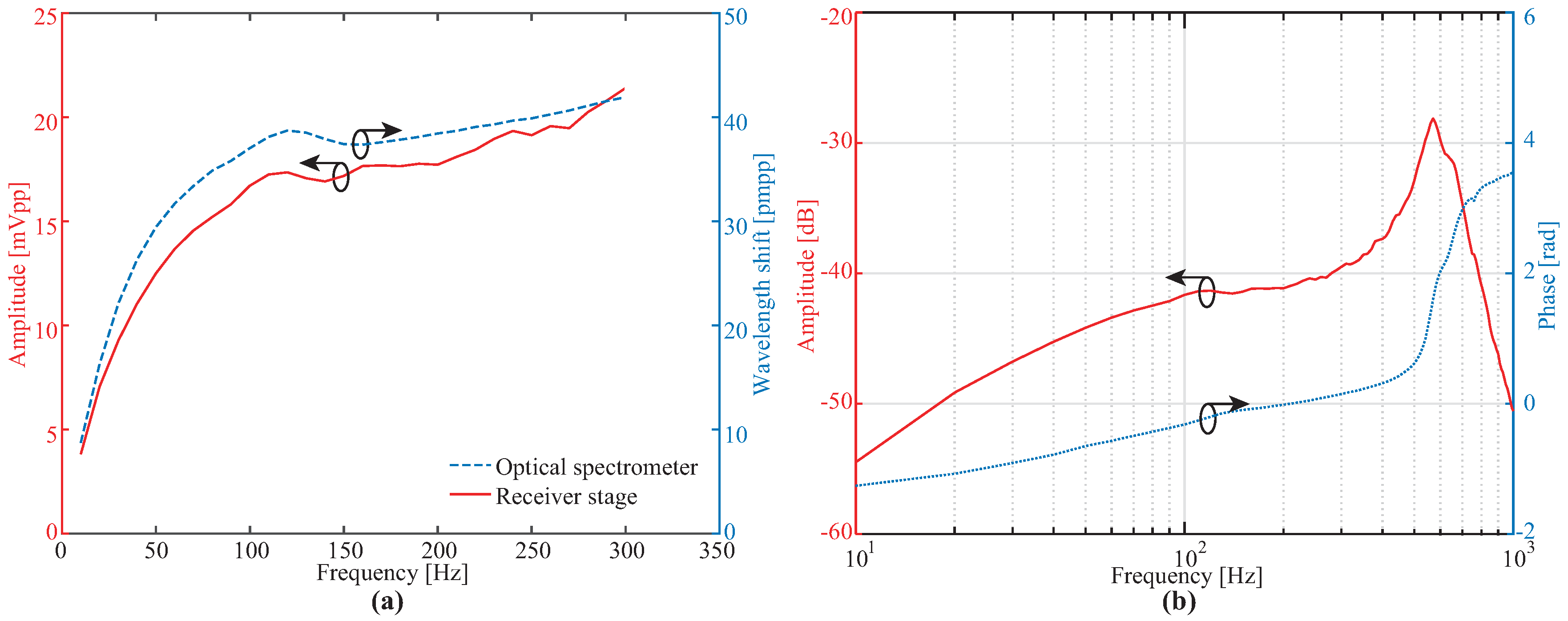
3.1. Edge-Filtering Optical-to-Electrical Characterization ( M 1 Vs. M 2 )

In order to see the role played by our edge-filtering proposal on the analog channel performance, the wavelength and amplitude shifts, as function of the modulation signal frequency for a constant amplitude of 2 Vpp, are presented in Figure 5a. As expected, the wavelength shift trend (acquired with the Ibsen spectrometer) shows a similar behavior for the electrical amplitude measured at the receiver. By assuming a linear relation between both curves, the discriminator and detector conversion factor is ∼2 pmpp/mVpp, for a frequency of 300 Hz. Based on this result, we can see that our low-cost O/E performs as well as costly fast FBG interrogation systems.

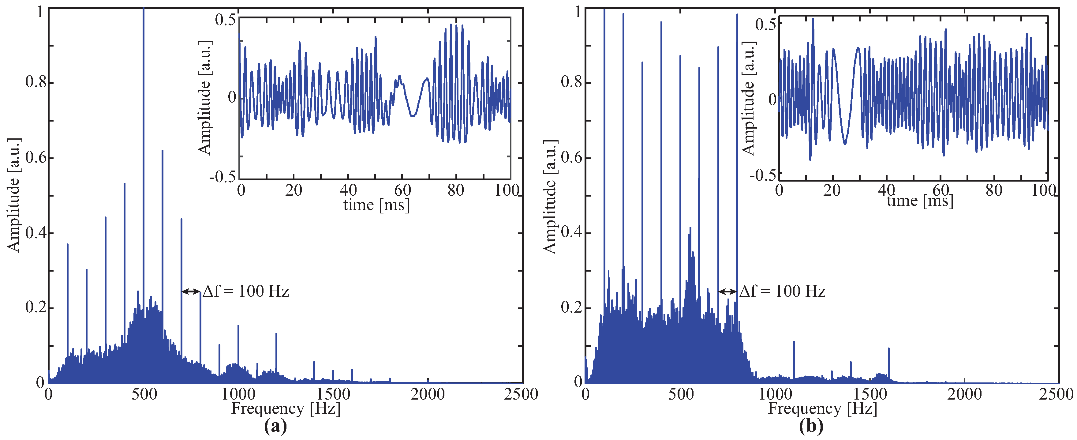
3.2. Analog Communication Channel Characterization ( M 2 )

Figure 5b depicts the frequency characterization of the AOM, in both amplitude and phase. As observed, the resonance frequency is ∼570 Hz. Additionally, it can be seen that for extreme frequencies, namely, values lower than 50 Hz and higher than 900 Hz, the amplitude is attenuated more than 45 dB, therefore limiting the effective bandwidth of this solution in ∼800 Hz. Finally, the delay is drastically increased for frequencies near the resonance frequency.

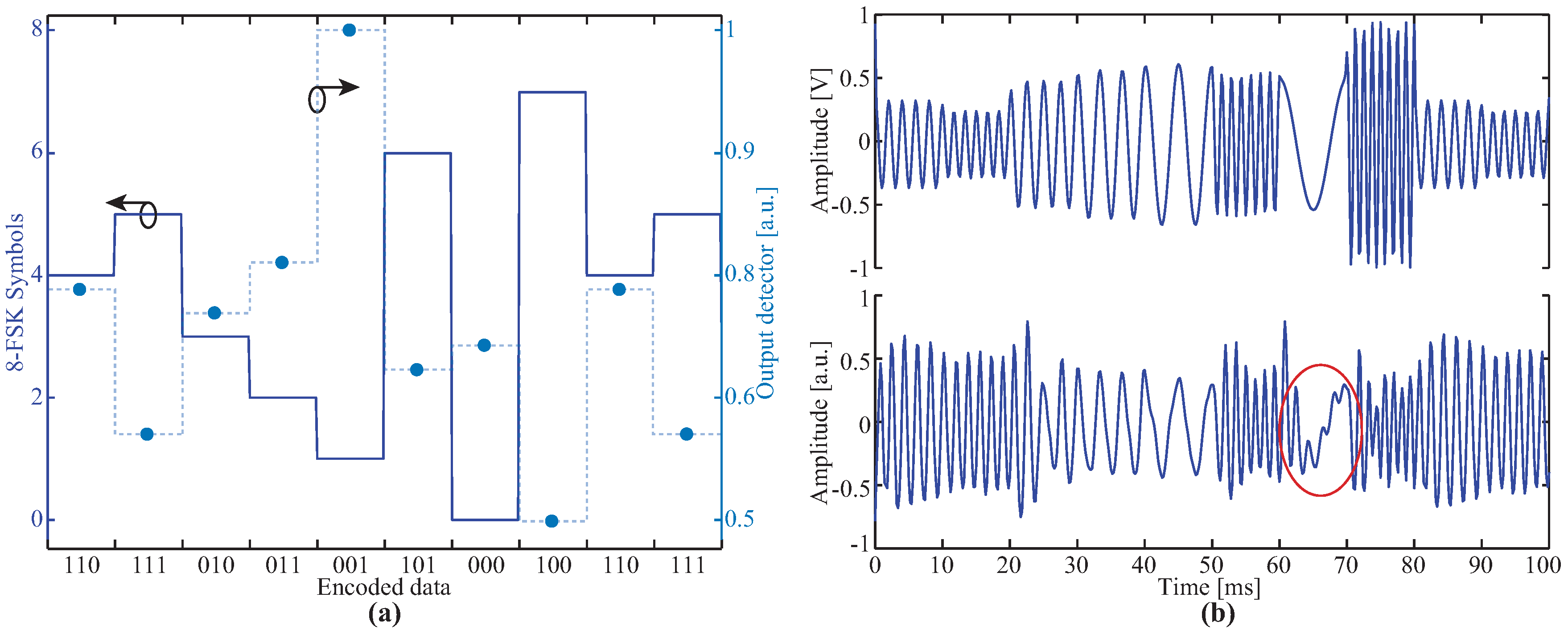
3.2.1. Interaction of Codification-Modulation Device with Communication Channel

Figure 6 shows the pulse response of the system and the modulation electric signal in solid and dashed lines, respectively. As it can be observed, for pulse periods lower than 2.5 ms, the underdamped response was increased. The resonance frequency of the system (570 Hz) was evidenced in the underdamped temporal response. Therefore, if either OOK or ASK modulation were used, the intersymbol interference (ISI) would be drastically increased when compared with FSK modulation, which is a good candidate for the proposed modulation scheme. Although, FSK does not guarantee total free ISI. This event was evidenced in the large transition from high to low frequencies of the sub–carriers (such as variations from 700 Hz to 100 Hz).
By using the system transfer function, it is possible to pre-emphasise the signal amplitude, phase, or both, in order to improve the demodulation process. Since the square-law detector was applied to demodulate the signal, the issue related with the phase component can be neglected [36]. For amplitude pre-emphasis, the modulation carrier was multiplied by the inverse function of the amplitude response, presented in Figure 5b.
Figure 7 displays the fast Fourier transform of the received signals for 8-FSK modulation in both cases: uncompensated (a) and applying pre-emphasis equalization (b), for an arbitrary symbols sequence with 3000 bits. The uncompensated spectrum response shows an unleveled amplitude of the carriers. On the other hand, the pre-emphasis spectrum response shows a subcarriers’ amplitude distribution which is more equalized, which simplifies the demodulation process and improves the overall system performance. The right corner inset of both figures depict the received signal temporal evolution for an arbitrary period, being evidenced the effect of the time-domain pre-emphasis.

3.2.2. Electrical-to-Digital and Digital-to-Information Conversion Issues

An example of the 8-FSK encoded data is shown in Figure 8a, where it is observed all the symbols (0 to 7), for three bits combination, that can be encoded. Gray’s codification was implemented in the CMD at I/E in order to reduce the impact of symbol error rate over bit error statistics. Superimposed to Figure 8a, it can be seen the normalized mean value of the square-law output detector for each of the 8-FSK symbols, presented in dots. The maximum correlation between the modulation and received signals is verified in the symbol 1 (200 Hz). This fact can be attributed to the zero phase delay for this frequency (see Figure 5b). On the other hand, the lowest correlation was achieved with the symbol 7 (800 Hz). Two factors contribute to this fact: first, for higher frequencies less samples were acquired, inducing errors in the envelope result; second, the phase delay reduces the amplitude output of the correlators. Figure 8b depicts the modulation and received signals for 8-FSK modulation, in the back-to-back connection. In this example, it can be seen, in the transition from higher to lower frequency sub-carriers (marked with a circle), that the 100 Hz wave has superimposed a harmonic component of the natural frequency. When the diaphragm undergoes a strong oscillation change, the underdamped response required around 12 ms to stabilize, which is higher than the minimum period of symbol. This effect can be considered as ISI and, in the opposite cases (lower to higher oscillation frequencies) or neighbor sub-carriers, it did not affect the wave shape.

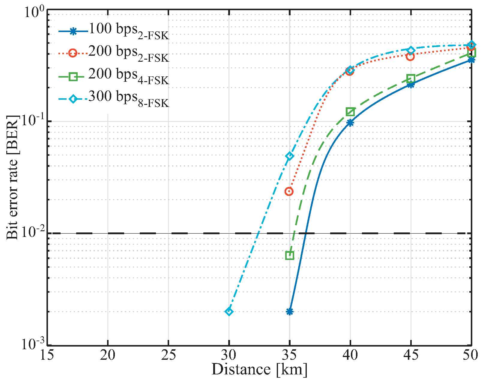
3.3. Digital Communication Channel Characterization ( M 3 )

In order to analyze the system performance in a field deployment, we tested the achieved BER as a function of the attenuation imposed by the transmission channel, illustrated in Figure 9 assuming 0.2 dB/km. As expected, for the highest baud rate (300 bps), FBG-based IoToF was less tolerant to link attenuation. The horizontal dashed line represents the reach of our FBG-based IoToF. This threshold value was based on the receiver sensitivity of narrowband wireless systems (usually defined at bit error rate (BER) of 1% [38,39]). Figure 9 shows that even at 300 bps, reach can exceed 30 km.
The requirements presented in Table 1 and in Figure 1 can be met by the developed simple and low-cost setup [11,12] (AOM ∼100 euros, commercial value of FBG). Actually, our PHY prototype for IoToF exceeds LoRa and Sigfox reach wide area transmission by providing 300 bps raw transmission for more than 30 km long links. There is plenty of room for improvements. More elaborated E/A structures would improve the acoustic channel. The use of forward error corrector and more powerful broadband source would extend reach beyond hundred of kilometers. More elaborated modulation and coding strategies, than elementary M-FSK, can boost IoToF spectral efficiency, improving the end-user bit rate.

4. Conclusions

This work made a case for IoToF focusing on niche applications which require low data rates along extended reach links. It presented an innovative low-cost FBG based acousto-optic modulation scheme suitable for IoT demands. A simple implementation with off-the-shelf components was able to upstream 300 bps with 8-FSK over links exceeded ∼30 km, which can unleash IoT applications beyond the limits of LoRa and Sigfox. The proposed scheme can be extended to multiple devices due to the multiplexing flexibility offered by the FBG technology. A proper short framing link layer solution over IoToF PHY should also be developed as future work. Another important parameter is the AOM’s power consumption, and IoToF device autonomy as a result. We envisage that distributed Raman amplification can be used to extend reach while its pump power recycling is used for power transmission over optical fiber as an ingenious solution that could be applicable for feeding IoToF devices [40]. In addition, an important challenge related with the receiver stage of the IoToF needs to be addressed. Despite the edge-filtering technique allows to interrogate FBGs with high frequency and low-cost, the channel multiplexing is a common issue among the proposed techniques in the state-of-the-art. Commercial devices such coarse or dense WDMs can be used as multichannel edge-filters, increasing the interrogation cost when compared with techniques proposed in the state of the art. Therefore, it is necessary to develop novel strategies or devices to perform the edge-filtering process keeping in mind the low-cost approach. In AOMs fabrication terms, it is necessary to propose more compact and sensitivity devices. In addition, to increase the bit rate is the main aim. Finally, a more realistic scenario with several AOMs and IoT devices need to be implemented to validate the overall performance of the IoToF approach. All underlying data used in this publication can be found [https://doi.org/10.5281/zenodo.2602184].

Author Contributions

P.F.C.A., P.S.A. and C.A.M. conceived and designed the experiments; C.A.R.D., C.L. and M.F.D. performed the experiments; T.R. and A.F. analyzed the data; M.J.P. and N.A. contributed materials/analysis tools/revised the paper; C.A.R.D. and M.R.N.R. wrote the paper.

Funding

This research received no external funding.

Acknowledgments

This work was partially supported by Petrobras S.A. 2017-00702/6, CAPES-financing code 001, CNPq-408480/2018-1, FAPES, in the scope of PVE/CNPq407093/2013-3, Instituto de Telecomunicações, Aveiro, and Institute of Nanostructures, Nanomodelling and Nanofabrication. This work was financed in the scope of programs UID/EEA/50008/2013, UID/ CTM/50025/2013 and UID/EEA/50008/2019, by the National Funds through the Fundação para a Ciência e a Tecnologia (FCT)/ Ministério da Educação e Ciência, and by the European Regional Development Fund under the PT2020 Partnership Agreement. This work is also funded by national funds (OE), through FCT, I.P., in the scope of the framework contract foreseen in the numbers 4, 5 and 6 of the article 23, of the Decree-Law 57/2016, of August 29, changed by Law 57/2017, of July 19. Nélia Alberto and M. Fátima Domingues thank the support received from the PREDICT (FCT-IT-LA) and REAct (FCT-IL-LA) scientific actions, respectively. FUTEBOL has received funding from the European Union’s Horizon 2020 for research, technological development, and demonstration under grant agreement No. 688941 (FUTEBOL), as well from the Brazilian Ministry of Science, Technology and Innovation (MCTI) through RNP and CTIC.

Conflicts of Interest

The authors declare no conflict of interest. The founding sponsors had no role in the design of the study; in the collection, analyses, or interpretation of data; in the writing of the manuscript, and in the decision to publish the results.

References

  1. Tokognon, C.A.; Gao, B.; Tian, G.Y.; Yan, Y. Structural Health Monitoring Framework Based on Internet of Things: A Survey. IEEE Internet Things J. 2017, 4, 619–635. [Google Scholar] [CrossRef]
  2. Catarinucci, L.; de Donno, D.; Mainetti, L.; Palano, L.; Patrono, L.; Stefanizzi, M.L.; Tarricone, L. An IoT-Aware Architecture for Smart Healthcare Systems. IEEE Internet Things J. 2015, 2, 515–526. [Google Scholar] [CrossRef]
  3. Kulkarni, A.; Sathe, S. Healthcare applications of the Internet of Things: A Review. Int. J. Comput. Sci. Inf. Technol. 2014, 5, 6229–6232. [Google Scholar]
  4. Zanella, A.; Bui, N.; Castellani, A.; Vangelista, L.; Zorzi, M. Internet of Things for Smart Cities. IEEE Internet Things J. 2014, 1, 22–32. [Google Scholar] [CrossRef]
  5. Lee, S. Communication Technology and Application of Internet of Things (IoT) in Smart Home Environment. Int. J. Comput. Appl. 2017, 10, 397–404. [Google Scholar] [CrossRef]
  6. Madakam, S.; Ramaswamy, R.; Tripathi, S. Internet of Things (IoT): A Literature Review. J. Comput. Commun. 2015, 3, 164–173. [Google Scholar] [CrossRef]
  7. Shang, Y. Vulnerability of networks: Fractional percolation on random graphs. Phys. Rev. E 2014, 89, 012813. [Google Scholar] [CrossRef] [PubMed]
  8. Wydra, M.; Kisala, P.; Harasim, D.; Kacejko, P. Overhead Transmission Line Sag Estimation Using a Simple Optomechanical System with Chirped Fiber Bragg Gratings. Part 1: Preliminary Measurements. Sensors 2018, 18, 309. [Google Scholar] [CrossRef] [PubMed]
  9. Díaz, C.A.R.; Leal-Junior, A.G.; Andrdé, P.S.B.; da Costa Antunes, P.F.; Pontes, M.J.; Frizera-Neto, A.; Ribeiro, M.R.N. Liquid Level Measurement Based on FBG-Embedded Diaphragms with Temperature Compensation. IEEE Sens. J. 2018, 18, 193–200. [Google Scholar] [CrossRef]
  10. da Silva Marques, R.; Prado, A.R.; da Costa Antunes, P.F.; de Brito André, P.S.; Ribeiro, M.; Frizera-Neto, A.; Pontes, M.J. Corrosion Resistant FBG-based quasi-distributed sensor for crude oil tank dynamic temperature profile monitoring. Sensors 2015, 15, 30693–30703. [Google Scholar] [CrossRef] [PubMed]
  11. Díaz, C.A.; Marques, C.A.; Domingues, M.F.F.; Ribeiro, M.R.; Frizera-Neto, A.; Pontes, M.J.; André, P.S.; Antunes, P.F. A cost-effective edge-filter based FBG interrogator using catastrophic fuse effect micro-cavity interferometers. Measurement 2018, 124, 486–493. [Google Scholar] [CrossRef]
  12. Díaz, C.A.R.; Leitão, C.; Marques, C.A.; Domingues, M.F.; Alberto, N.; Pontes, M.J.; Frizera, A.; Ribeiro, M.R.N.; André, P.S.B.; Antunes, P.F.C. Low-Cost Interrogation Technique for Dynamic Measurements with FBG-Based Devices. Sensors 2017, 17, 2414. [Google Scholar] [CrossRef] [PubMed]
  13. Al-Sarawi, S.; Anbar, M.; Alieyan, K.; Alzubaidi, M. Internet of Things (IoT) communication protocols: Review. In Proceedings of the 2017 8th International Conference on Information Technology (ICIT), Amman, Jordan, 17–18 May 2017; pp. 685–690. [Google Scholar]
  14. Lethaby, N. Wireless Connectivity for the Internet of Things: One Size Does Not Fit All; Technical Report; Texas Instruments: Dallas, TX, USA, 2017. [Google Scholar]
  15. Mainetti, L.; Patrono, L.; Vilei, A. Evolution of wireless sensor networks towards the Internet of Things: A survey. In Proceedings of the SoftCOM 2011, 19th International Conference on Software, Telecommunications and Computer Networks, Split, Croatia, 15–17 September 2011; pp. 1–6. [Google Scholar]
  16. Atzori, L.; Iera, A.; Morabito, G. The Internet of Things: A survey. Comput. Netw. 2010, 54, 2787–2805. [Google Scholar] [CrossRef]
  17. Li, B.; Yu, J. Research and Application on the Smart Home Based on Component Technologies and Internet of Things. Procedia Eng. 2011, 15, 2087–2092. [Google Scholar] [CrossRef] [Green Version]
  18. Borgia, E. The Internet of Things vision: Key features, applications and open issues. Comput. Commun. 2014, 54, 1–31. [Google Scholar] [CrossRef]
  19. Guibene, W.; Nolan, K.E.; Kelly, M.Y. Survey on Clean Slate Cellular-IoT Standard Proposals. In Proceedings of the 2015 IEEE International Conference on Computer and Information Technology; Ubiquitous Computing and Communications; Dependable, Autonomic and Secure Computing; Pervasive Intelligence and Computing, Liverpool, UK, 26–28 October 2015; pp. 1596–1599. [Google Scholar]
  20. Wydra, M.; Kubaczynski, P.; Mazur, K.; Ksiezopolski, B. Time-Aware Monitoring of Overhead Transmission Line Sag and Temperature with LoRa Communication. Energies 2019, 12, 505. [Google Scholar] [CrossRef]
  21. Mazur, K.; Wydra, M.; Ksiezopolski, B. Secure and Time-Aware Communication of Wireless Sensors Monitoring Overhead Transmission Lines. Sensors 2017, 17, 1610. [Google Scholar] [CrossRef] [PubMed]
  22. Senior, J.M. Optical Fiber Communications Principles and Practice, 3rd ed.; Pearson Education: London, UK, 2009. [Google Scholar]
  23. Ji, P.N.; Wang, T. Internet of things with optical connectivity, networking, and beyond. In Proceedings of the 2016 21st OptoElectronics and Communications Conference (OECC) Held Jointly with 2016 International Conference on Photonics in Switching (PS), Niigata, Japan, 3–7 July 2016; pp. 1–3. [Google Scholar]
  24. Sanctis, M.D.; Cianca, E.; Araniti, G.; Bisio, I.; Prasad, R. Satellite Communications Supporting Internet of Remote Things. IEEE Internet Things J. 2016, 3, 113–123. [Google Scholar] [CrossRef]
  25. Larsen, C.P.; Gavler, A.; Wang, K. Comparison of active and passive optical access networks. In Proceedings of the 2010 9th Conference of Telecommunication, Media and Internet, Ghent, Belgium, 7–9 June 2010; pp. 1–5. [Google Scholar]
  26. Vetter, P.; Suvakovic, D.; Chow, H.; Anthapadmanabhan, P.; Kanonakis, K.; Lee, K.L.; Saliou, F.; Yin, X.; Lannoo, B. Energy-efficiency improvements for optical access. IEEE Commun. Mag. 2014, 52, 136–144. [Google Scholar] [CrossRef] [Green Version]
  27. Haslett, C. Essentials of Radio Wave Propagation, 1st ed.; Cambridge University Press: Cambridge, UK, 2008. [Google Scholar]
  28. Winder, S.; Carr, J.J.; Davies, J. Newnes Radio and RF Engineering Pocket Book, 3rd ed.; Elsevier: Amsterdam, The Netherlands, 2002. [Google Scholar]
  29. Skubic, B.; de Betou, E.I.; Ayhan, T.; Dahlfort, S. Energy-efficient next-generation optical access networks. IEEE Commun. Mag. 2012, 50, 122–127. [Google Scholar] [CrossRef]
  30. Yan, L.; Wu, Z.; Zhang, Z.; Pan, W.; Luo, B.; Wang, P. High-Speed FBG-Based Fiber Sensor Networks for Semidistributed Strain Measurements. IEEE Photonics J. 2013, 5, 7200507. [Google Scholar]
  31. Pachava, V.R.; Kamineni, S.; Madhuvarasu, S.S.; Putha, K.; Mamidi, V.R. FBG based high sensitive pressure sensor and its low-cost interrogation system with enhanced resolution. Photonic Sens. 2015, 5, 321–329. [Google Scholar] [CrossRef] [Green Version]
  32. Srivastava, D.; Bhatnagar, R.; Kumar, A.; Parmar, V. Intensity modulation using chirped fiber bragg grating as an edge filter for temperature sensing. Microw. Opt. Technol. Lett. 2014, 56, 2913–2915. [Google Scholar] [CrossRef]
  33. Guo, T.; Tam, H.Y.; Albert, J. Chirped and tilted fiber Bragg grating edge filter for in-fiber sensor interrogation. In CLEO: Science and Innovations; Optical Society of America: Washington, DC, USA, 2011; p. CThL3. [Google Scholar]
  34. Tiwari, U.; Thyagarajan, K.; Shenoy, M.R.; Jain, S.C. EDF-Based Edge-Filter Interrogation Scheme for FBG Sensors. IEEE Sens. J. 2013, 13, 1315–1319. [Google Scholar] [CrossRef]
  35. Wei, L.; Khattak, A.; Martz, C.; Zhou, D.P. Tunable Multimode Fiber Based Filter and Its Application in Cost-Effective Interrogation of Fiber-Optic Temperature Sensors. IEEE Sens. J. 2017, 9, 1–8. [Google Scholar] [CrossRef] [Green Version]
  36. Proakis, J.G.; Salehi, M.; Bauch, G. Contemporary Communication Systems Using MATLAB, 3rd ed.; Nelson Education: Scarborough, ON, Canada, 2013. [Google Scholar]
  37. Peucheret, C.; Liu, F.; Pedersen, R.J.S. Measurement of small dispersion values in optical components [WDM networks]. Electron. Lett. 1999, 35, 409–411. [Google Scholar] [CrossRef]
  38. CC1120 High-Performance RF Transceiver for Narrowband Systems; Technical Report; Texas Instruments: Dallas, TX, USA, 2015.
  39. Hayashi, G.; Sawada, A.; Morie, T.; Matsuyama, K.; Kim, R.; Yoshida, S.; Matsumoto, A.; Hijikata, K.; Matsukawa, K.; Tamura, Y.; et al. A 10.8mA Single Chip Transceiver for 430MHz Narrowband Systems in 0.15/spl mu/m CMOS. In Proceedings of the 2006 IEEE International Solid State Circuits Conference—Digest of Technical Papers, San Francisco, CA, USA, 6–9 February 2006; pp. 1480–1489. [Google Scholar]
  40. André, P.; Lima, M.J.N.; Rocha, A.M.; Fernandes, N.; Granada, M.; Almeida, T.; Chang, J.; Lan, R.; Xin, X.-J. Raman amplified access networks with pump signal recycling for electrical power conversion. Microw. Opt. Technol. Lett. 2012, 54, 116–119. [Google Scholar] [CrossRef]
Figure 1. Relation between bandwidth and range for wireless IoT standards and passive optical networks (PONs)-based communication networks with the inclusion of the IoToF concept here proposed.
Electronics 08 00359 g001
Figure 2. (a) Schematic of the proposed IoToF approach used to interlink several IoT devices to a receiver and (b) scheme of the fiber Bragg grating (FBG) operation principle.
Electronics 08 00359 g002
Figure 3. Flowchart of the physical connectivity (PHY) sublayer communication. I/E: information-to-electrical, E/A: electrical-to-acoustic, A/O: acoustic-to-optical, O/E: optical-to-electrical, E/D: electrical-to-digital, and D/I: digital-to-information conversions. M 1 , M 2 , and M 3 , represent the measurement points used for the system characterization.
Electronics 08 00359 g003
Figure 4. A low-cost acousto-optical modulator (AOM) implementation with a FBG connected to a loudspeaker.
Electronics 08 00359 g004
Figure 5. (a) Peak to peak relation between wavelength shift and electrical amplitude as a function of the modulation frequency and (b) transfer function of the proposed AOM.
Electronics 08 00359 g005
Figure 6. AOM step response for different pulse width. Solid line is the measured response at the receiver and the dashed line is the applied electric signal.
Electronics 08 00359 g006
Figure 7. Spectra and temporal responses for 8-FSK: (a) uncompensated and (b) pre-emphasis equalization.
Electronics 08 00359 g007
Figure 8. (a) 8-FSK encoded data symbols, (b) modulation and received signal for 8-FSK in back to back configuration.
Electronics 08 00359 g008
Figure 9. Bit error rate (BER) as a function of the transmission distance.
Electronics 08 00359 g009
Table 1. The internet of things (IoT) requirements and conventional optical physical connectivity (PHY) at Optical network unit (ONU) and IoT over fiber (IoToF) optical PHY.
IoT RequirimentsConventional Optical
PHY @ ONU
(per Subscriber [26])
IoToF Optical
PHY
ThroughputUp to 2.5 GbpsAt least 100 bps
RangeUp to 20 kmAt least 20 km
Power ConsumptionAround 1 W0 W ( P a s s i v e )

