Article

LLC Resonant Converter for LEV (Light Electric Vehicle) Fast Chargers

1
School of Electrical Engineering, Pusan National University, Busandaehak-ro 63 beon-gil 2, Busan 46241, Korea
2
Technical Research Center, Taeyang Mechatronics Corporation, 40 Gwahaksandan 2-ro 3beon-gil Gangseo-Gu, Busan 46742, Korea
*
Author to whom correspondence should be addressed.
Electronics 2019, 8(3), 362; https://doi.org/10.3390/electronics8030362
Submission received: 22 February 2019 / Revised: 18 March 2019 / Accepted: 22 March 2019 / Published: 25 March 2019
(This article belongs to the Section Electrical and Autonomous Vehicles)

Abstract

:
This paper presents a Light Electric Vehicle (LEV) fast charger with a Lithium-Ion Battery (LIB) and Super-Capacitor (SC). The LEV fast charger consists of an AC/DC rectifier and LLC (Inductor-Inductor-Capacitor) resonant Full bridge converter. The LLC resonant converter has high-efficiency and low switching loss because of Zero Voltage Switching (ZVS). So, it is used widely in the industry. In general, the fast charger algorithm uses the Constant Current (CC) mode and Constant Voltage (CV). The CC mode starts at first and then the CV mode finishes. However, there is a big control value gap between the CC mode and CV mode. Therefore, when changing from CC to CV, the transient state occurs. To compensate for the transient state, we propose a new control algorithm. By means of this algorithm, we can achieve a higher level of safety and stability. The fast charger with LIB of 800 Wh and SC of 50 Wh is analyzed and verified, and we obtain a maximum efficiency of 96.4%. The discussions are validated using the LLC resonant full bridge converter prototype at the laboratory level.

1. Introduction

Nowadays, environmental pollution and air pollution are key global issues. Especially automobiles using gasoline and diesel fuel as they are the main cause of air and environmental pollution due to their exhaust gas. As a result, the demand for environmentally-friendly Electric Vehicles (EVs) and LEV is increasing and its market share is getting bigger day by day. LEVs are electric vehicles with 2 or 4 wheels driven by a fuel cell, battery, or are hybrid-powered, and normally weighing less than 100 kg, for example, electric bicycles, kickboards and wheelchairs. EVs and LEVs cause the air to be clean as they do not exhaust gas. In addition, EVs and LEVs have the advantage of requiring less maintenance and creating less noise compared to diesel or gasoline vehicles. However, they need very high periods of charging time. Therefore, it is necessary to develop EVs and LEVs with a short charging time. Recently, the technology for fast charging has been to increase the power (W). In other words, to increase the power (W) is to increase the voltage (V) or current (A). If the voltage is increased, a potential difference occurs between the battery and converter output voltages. Because of this, the charging current increases. In the case of the EV charging system, lots of research on high-efficiency converters and fast charging topologies are being conducted now. On the other hand, LEV charging system research is still rare compared to EV research [1,2,3,4,5].
Generally, LEV systems often use inexpensive lead-acid batteries. However, lead-acid batteries are environmentally harmful and have a low Current rate (C-rate). In addition, most fast chargers for LEV in public usage are designed and fabricated for lead-acid batteries. In the case of a fast charging system, high-frequency switching is required to reduce the system size with the ZVS and ZCS (Zero Current Switching) techniques which have switching loss reduction [6,7,8,9,10].
The LLC resonant full-bridge converter is used widely in different industries and applications due to some important features such as high-power density, high efficiency, and cost-effectiveness [11,12]. ZVS at the turn-on and low turn-off currents of the MOSFETs in this converter makes the switching loss negligible, so, the switching frequency can be increased to produce a lightweight power supply for a LEV fast-charging system.
A fast-charging system usually consists of CV, CC, and CC-CV mode algorithms. The CV is a method of controlling the constant voltage applied to the battery. If the voltage difference of the initial battery is large, a large current may flow, so a limiter that limits the current is needed. The CC is a method for controlling the constant current to be applied to the battery differently from the CV mode. The battery is charged with a constant current from the beginning of the charging cycle to the end of it. If the charging current and time are not controlled correctly, the battery is damaged by overcharging [13,14].
CC-CV starts at CC at the beginning of the charging cycle and changes into the CV state when it reaches a certain State of Charge (SOC). In the initial state, the charging starts the CC mode. The CC mode operates with a high control current. Therefore, it can rapidly reach a SOC of 80~90%. If the SOC approaches 80~90%, the CC mode is stopped and the CV mode is started. The SOC can reach 100% in the CV mode [15,16,17,18,19].
In conventional studies of the CC and CV methods, various solutions to solve the problem have been presented. However, many studies have attempted to adjust the hardware to meet the wide output current and voltage or optimal circuit parameters [19,20]. In other previous research, they tried to remove the transient state during the mode transfer with an additional circuit. However, this method is not good because of the complexes caused by surplus hardware [21,22].
We propose a fast charger prototype of a LEV with a LIB of 800 Wh and SC of 50 Wh. This fast charger prototype consists of an AC/DC rectifier and DC/DC stage. The DC/DC stage has a full bridge LLC resonant converter for soft switching and reducing the switching stress. In addition, it is controlled by a Pulse Frequency Modulation (PFM) and PI controller with an algorithm of CC-CV transformation.
The rest of this paper is organized as follows: an LLC resonant converter including the ZVS condition is demonstrated in Section 2. The proposed fast-charging system is tested in Section 3. The control algorithm of the proposed method is described in Section 4. Additionally, the experimental results are illustrated in Section 5. Finally, the conclusions are given in Section 6.

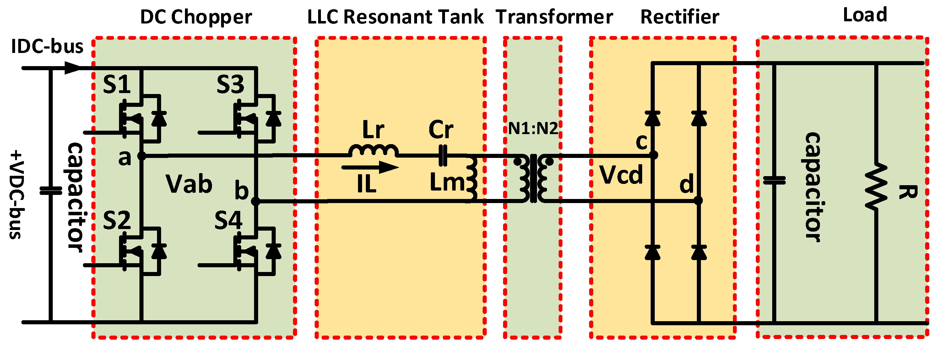
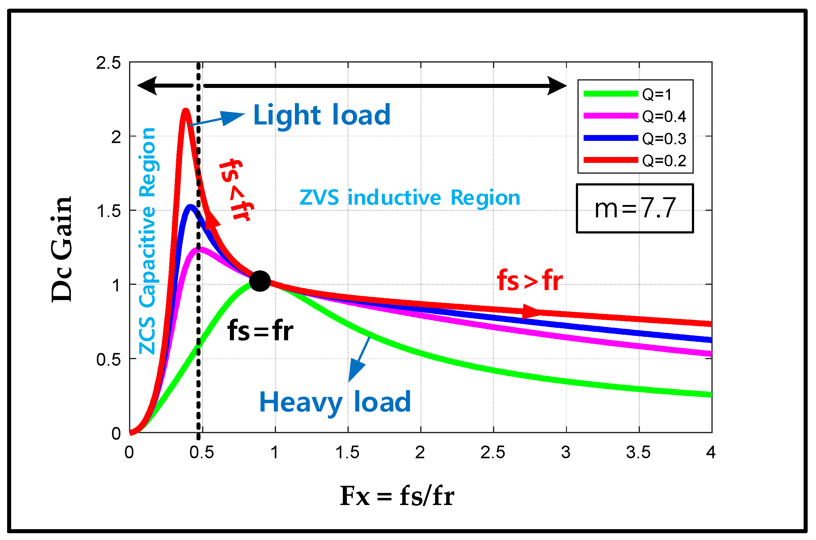
2. LLC Resonant Converter

The LLC resonant converter consists of two series-parallel inductors. Referring to Figure 1, it shows two inductors and one capacitor. It has the same shape as the series resonant converter using a transformer, but uses the magnetization inductance of the transformer as the resonant element. In addition, the problem of no-load control occurring in the series resonant converter due to the magnetizing current can be cleared.
As with other resonant converters, a square wave voltage Vab is formed due to the switching action, and acts as a filter for IL due to the series resonant inductor Lr and the resonant capacitor Cr. Additionally, the magnetizing current circulated through the magnetizing inductance Lm is also affected by the resonance capacitor Cr. Therefore, the LLC resonant converter has two resonant frequencies. The Lr and Cr elements form the high resonance frequency, and the Lm, Lr and Cr elements form a low resonance frequency.
The resonant tank gain can be derived by analyzing the equivalent resonant circuits shown in Figure 2. The resonant tank gain is the magnitude of its transfer function as in Equation (1).
| V o _ a c ( s ) V i n _ a c ( s ) | = F x 2 ( m 1 ) ( m · F x 2 1 ) 2 + F x 2 · ( F x 2 1 ) 2 · ( m 1 ) 2 · Q 2
where, Q (Quality factor) is expressed by Equation (2).
Q = L r / C r R a c
Equation (3) can be expressed by the ratio of total primary inductance to resonant inductance, Rac is the reflected load resistance, so, it can be expressed by Equation (4).
m = L r + L m L r
R a c = 8 π 2 · N p 2 N s 2 · R o
Fx is the normalized switching frequency. It can be expressed by Equation (5) and Equation (6) can be expressed by resonant frequency [19].
F x = f s f r
f r = 1 2 π L r · C r
Figure 3 shows the resonant tank voltage gain curve; these graphs express Equation (1). It is decided by the Q and m. Additionally, the graph is drawn by MATLAB, version 2017 (MathWorks, Boston, MA, USA). Firstly, the Q factor is selected by the load condition because the Q factor affects the voltage regulation. In the case of a high operating Q, this means a heavy load. A low operating Q refers to a light load. A fast charger needs a high current for rapid charging. Therefore, it needs a high Q and operates in the resonant tank gain of 0.8~1.3. By considering these two factors, Q should be picked as 0.4. If the Q is higher or lower than 0.4, it has a different resonant tank gain and can use a high current control or low current control. The next step is to select the m. If the m has a low value, it has a higher boost gain, a narrower frequency range and a flexible regulation. On the other hand, a high m needs a higher magnetizing inductance, lower magnetizing circulating current and higher efficiency. Therefore, to get a high efficiency, the m should be between 6 to 10. However, if the select is over 8, the gain is low. So, the m is selected as 7.7 and that m is reflected in Figure 3. In conclusion, the fast charger is designed with Q = 0.4 and m = 7.7.
Referring to Figure 3, we can define the inductive and capacitive operation regions as the direction of the arrow in the plot. The capacitive and inductive regions are operated in the ZCS and ZVS regions. Our system gain curve is the pink color line of Figure 3. So, in order to operate in the ZVS region, our system should be controlled from 30 to 100 kHz [23,24,25].

3. The Proposed Fast-Charging System

Figure 4 shows the structure of our fast charger system. The system consists of the AC/DC rectifier, Full bridge LLC resonant converter and LEV battery. The fast charger uses the DSP (TMS320F28335) for controlling and sensing the system voltage and current. The LLC converter’s switching component is the gate of the MOSFET. By using a soft start for decreasing the inrush current initial start can reduce the switching stress. The system is controlled by PFM (Pulse Frequency Modulation) and PI control. In the case of a LEV battery with LIB and SC, a different control method for reducing the charging time is needed. The input and output voltage of this system each are each around 250~300 VAC (Voltage Alternating Current) and 25.6~33.6 VDC (Voltage Direct Current). In the case of the SC, the output voltage is around 0~48 V. Additionally, the system control current is 30 A.
Table 1 shows the specification of the fast charger. It shows each LIB and SC charging range.

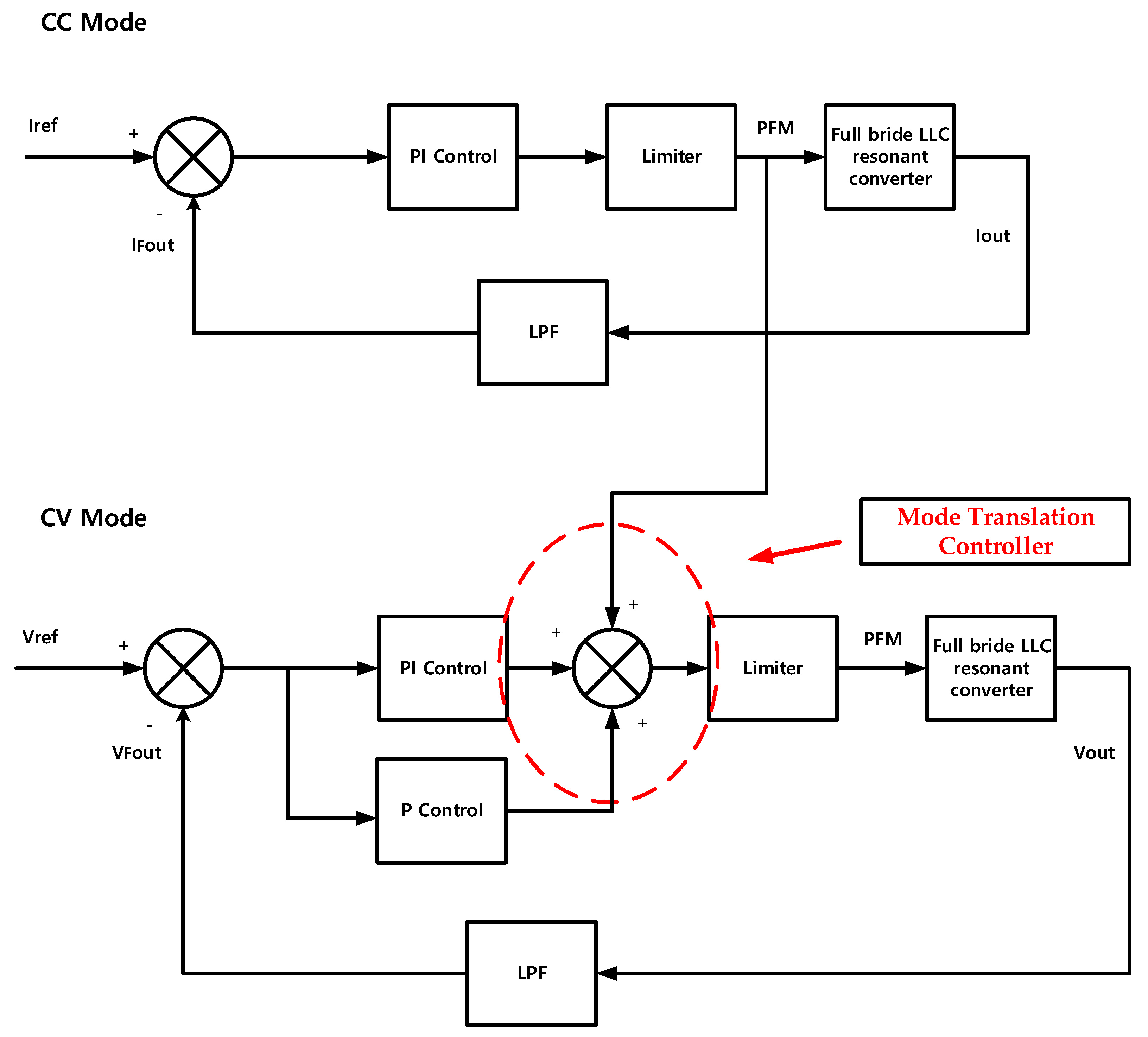
4. Control Algorithm of the Proposed Method

The EV and LEV Charger has a CC-CV mode. Initially, the method starts in the CC mode and then if it reaches a certain SOC, it changes to the CV mode. Figure 5 shows the characteristic curve of the CC-CV mode. The general method and the basic charging method of fast charging are almost the same. However, in the case of fast charging, a rated power of 10 times or more is required and larger current is also required [26,27].
Figure 6a shows the transient section of the fast charger. When changing from constant current to constant voltage, the transient section appears. In the case of a fast charger, a high current control is needed for the CC mode. So, the mode control changing gap is bigger. To solve this problem, we propose a new control algorithm and method.
The fast-charging devices use different control algorithms depending on the battery type. The CC-CV charging algorithm is applied for the LIB and the CC charging algorithm is applied for the SC. SC has different charging characteristics compared to LIB. By using the CC charging algorithm, we can charge more rapidly.
Firstly, the CC-CV charging algorithm for LIB can be divided into a series type and parallel type according to the controller structure. In the case of the series type, the voltage controller and the current controller are constructed in series. In this case, the current is not constant but gradually decreases while charging at a constant current, and the voltage is converted from a constant current to a constant voltage state. This method can perform charging in a stable manner, but takes a long time to charge. In the parallel type, the voltage controller and the current controller are configured in parallel and when the battery voltage rises from a set SOC after charging the battery to a constant current state, the voltage changes to the constant voltage state. In this method, the battery can be charged quickly at a constant current. However, the output of the controller should be applied when the charge state changes. Additionally, it does not reflect the output of the conventional controller [28,29].
We propose the CC-CV charging block diagram in Figure 7, which is supplemented with a compensation algorithm to solve the transient problem and achieve stable fast charging. Referring to Figure 7, the figure consists of the Proportional Integral (PI) control, Limiter, Proportional (P) control and Low Pass Filter (LPF). By using the LPF, the digital controller of the Analog-to-digital converter (ADC) quality is increased. The LPF can remove the noise. By using a PI controller in the CC mode which has been operating in the past, the CV mode can be compensated. The CV mode also starts with the same control value. So, initially, the CV mode can be started with the CC mode current. After using the P controller, the compensation value can be reduced. Finally, the CV control can be operated stably. From Figure 6a, it can be seen that the control value changes abruptly when the mode is changed in the state before applying the algorithm. On the other hand, from Figure 6b, it can be seen that the transient section decreases sharply after application [30].
Figure 8 shows the SC algorithm block diagram. It shows the CC Mode charging control. This consists of a PI control, Limiter and LPF. The SC has a small variation in the charging voltage during charging and completion of charging. Considering these characteristics, charging in the CC mode makes the charging time much faster [31].
Figure 9 shows the LIB charging algorithm. It uses DSP (TMS320F28335, Texas Instruments, Dallas, TX, USA) for controlling the fast charger. Initially, the controller receives the input/output voltage and input/output current data.
The power stage is protected by blocking the switching signals when overvoltage and overcurrent are checked. If it does not have any problems, the soft start function is started. If the duty ratio is 0.5 or the output current is over the 10 A, the soft start is finished.
When the LIB voltage is less than 33 V, the CC mode is started by the PI controller. Using the PI controller, we can change the PFM value. When CC the mode is operating, the PI controller tracks the 30 A current. When over 33 V, the CV mode is started by the PI controller. The charging task is terminated when the voltage finally reaches 33.6 V.
Figure 10 shows the SC charging algorithm. It also uses the DSP for charging control. Before the PI controller starts, its function is almost the same as that of the LIB controller. If this controller has a voltage less than 48 V, the CC mode is started. Additionally, charging is terminated at the moment the voltage reaches 48 V.
Both controllers track the 30 A. If we need to decrease the system charging time, it is possible to change the CC mode current. However, if the battery specification does not support a high current, we cannot apply this algorithm.
The experimental results and the efficiency using this algorithm are described in Section 5.

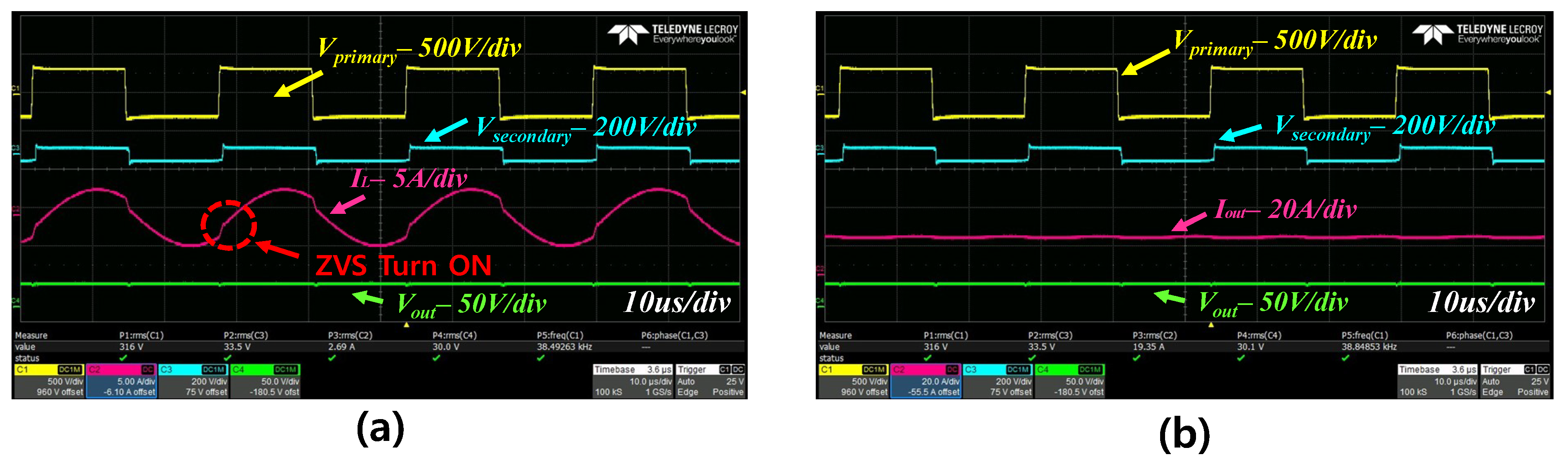
5. Experimental Results

A prototype of the full bridge LLC resonant converter was used for the experiments, as shown in Figure 11. Refer to Appendix A, it can check the detail of the battery.
Figure 12a,b show the LIB CC mode waveform of the LLC converter. The CC mode is controlled by PFM. The system keeps changing the frequency value for tracking the Iout. Through Figure 12b, the constant current can be confirmed. This mode almost has the same frequency as the resonant tank. The IL wave appears to be a sinusoidal waveform similar to that of the LLC converter characteristics. This mode can change rapidly due to the high current control. If the CC mode has a long time, this can reduce the charging time. However, if it does not have the CV mode, the LIB is not safe. As mentioned in Section 4, the frequency is operated in the ZVS region. We can confirm this from Figure 12a. By operating in the ZVS region, we can get a good soft-switching quality.
Figure 13a,b show the LIB CV mode waveform of the LLC converter. The CV mode is also controlled by PFM. The system keeps on changing the frequency for tracking the Vout. Through Figure 13b, we can check the frequency and Iout. They are different from the CC mode. This mode has a high frequency compared with that of the resonant tank. Therefore, the IL wave appears in a non-sinusoidal waveform which is similar to the LLC converter characteristics. This mode operates gradually with decreasing current and increasing Vout. Through this operation, a fast charger can be worked safely. This frequency operates in the ZVS region. This can be confirmed from Figure 13a. By operating in the ZVS region, it can also have soft-switching characteristics.
Figure 14 shows the CC mode charging waveform of the SC. In the case of LIB, it has the CC-CV controller. However, the SC only has the CC mode because it has low voltage regulation. The Iout tracks the reference value. Through Figure 14b, we can confirm that Iout is a constant current. Figure 14a shows the ZVS operation through the IL and Vprimary.
Compared with LIB and SC, they have the same Iout. However, they have different switching frequencies. Because LIB has a high load and SC has a low load, SC has low voltage regulation and it is possible to charge it to a much higher current.
Figure 15a is adapted without a compensator. Following this, Vout can be confirmed, switching the frequency and Iout. During the change from the CC mode to the CV mode, three factors abruptly change. These abrupt changes mean that the switching component has stresses. Figure 15b shows the improved CC-CV mode charging waveform. By compensating for the CV Mode, the transient effect does not appear.
Figure 16 shows the efficiency with the charging current at (a), (b), (c). All of the modes have different control values. In the case of Figure 16a, the maximum efficiency is 96.4% at 30 A. This was the closest region to the resonant frequency. In the case of Figure 16b, the maximum efficiency is 96.2% at 25 A. The CV mode has a resonant frequency of 25 A. In the case of Figure 16c, it is a light load. Therefore, the resonant region is at 50 A and the maximum efficiency is 96.4%.

6. Conclusions

In this paper, we proposed a fast-charging device using an LLC resonant converter with soft switching characteristics in the ZVS region. In the case of lead-acid batteries used in the past, their frequent usage is being reduced due to the air and environmental pollution. Therefore, we propose this new LEV system that has a fast-charging scheme with a LIB of 800 Wh and SC of 50 Wh. The previous LIB charging device has a long charging time of more than 2 h. This proposed fast-charging LIB system has the charging time of about 1 h. Additionally, this proposed fast-charging SC system has a charging time of about 20 min. In the case of LIB, the compensation algorithm is implemented by reducing the transient period during the conversion from the CC mode to the CV mode. Finally, the maximum conversion efficiency of the output current of 30 A in the CC mode is 96.4%.

Author Contributions

D.-H.K., H.-J.K. conceptualized the idea of this research project. D.-H.K., C.-H.K. designed the structure and components of LLC resonant converter. D.-H.K., M.-S.K. and S.H.N. designed a PCB board. D.-H.K. and M.-S.K. developed the control algorithm and DSP program of LLC converter. D.-H.K. made an experimental setup and did experiment. The data was analyzed by the authors and the paper was written by D.-H.K. and H.-J.K.

Funding

This research was supported by Brain Korea 21 Center for Creative Human Resource Development Program for IT Convergence of Pusan National University. And supported by Korea Industrial Complex Corporation of Ministry of Trade, Industry and Energy [RBS18002].

Acknowledgments

This research was supported by Brain Korea 21 Center for Creative Human Resource Development Program for IT Convergence of Pusan National University. And supported by Korea Industrial Complex Corporation of Ministry of Trade, Industry and Energy [RBS18002].

Conflicts of Interest

The authors declare no conflict of interest.

Appendix A

Table A1. LIB and SC Specification.
ListLi-ion (800 Wh)Super Capacitor (50 Wh)
Nominal Voltage29.2 V48 V
Charge Voltage33.6 V51 V
Max. Discharge Current30 A1900 A
Stored Energy800 Wh53 Wh

References

  1. Fu, Y.; Jia, C.; Huang, Y.; Ren, W. Influence of electric vehicles on reliability of power system containing wind power. In Proceedings of the 2017 IEEE Transportation Electrification Conference and Expo, Asia-Pacific (ITEC Asia-Pacific), Harbin, China, 7–10 August 2017; pp. 1–5. [Google Scholar]
  2. Bangalore, P.; Bertling, L. Extension of test system for distribution system reliability analysis with integration of Electric Vehicles in distribution system. In Proceedings of the 2011 2nd IEEE PES International Conference and Exhibition on Innovative Smart Grid Technologies, Manchester, UK, 5–7 December 2011; pp. 1–7. [Google Scholar]
  3. Gjelaj, M.; Træholt, C.; Hashemi, S.; Andersen, P.B. Cost-benefit analysis of a novel DC fast-charging station with a local battery storage for EVs. In Proceedings of the 2017 52nd International Universities Power Engineering Conference (UPEC), Heraklion, Greece, 28–31 August 2017; pp. 1–6. [Google Scholar]
  4. Sarker, M.R.; Pandzic, H.; Ortega-Vazquez, M.A. Optimal operation and services scheduling for an electric vehicle battery swapping station. IEEE Trans. Power Syst. 2015, 30, 901–910. [Google Scholar] [CrossRef]
  5. Zhou, M.; Wei, L.; Wen, J. The Parameters Matching and Simulation of Pure Electric Vehicle Composite Power Supply Based on CRUISE. Appl. Mech. Mater. 2014, 602, 2836–2839. [Google Scholar] [CrossRef]
  6. Chen, Z.; Ji, B.; Ji, F.; Shi, L. Analysis and Design Considerations of an Improved ZVS Full-Bridge DC-DC Converter. In Proceedings of the 2010 Twenty-Fifth Annual IEEE Applied Power Electronics Conference and Exposition (APEC), Palm Springs, CA, USA, 21–25 February 2010; pp. 1471–1476. [Google Scholar]
  7. Lee, I.O.; Moon, G.W. Analysis and design of phase-shifted dual H-bridge converter with a wide ZVS range and reduced output filter. IEEE Trans. Ind. Electron. 2013, 60, 4415–4426. [Google Scholar] [CrossRef]
  8. Chen, Z.; Liu, N.; Xiao, X.; Zhang, J. Energy exchange model of PV-based battery switch stations based on battery swap service and power distribution. In Proceedings of the 2013 IEEE Energy tech, Cleveland, OH, USA, 21–23 May 2013; pp. 1–6. [Google Scholar]
  9. Liu, C.; Gu, B.; Lai, J.S.; Wang, M.Y.; Ji, Y.C.; Cai, G.W.; Zhao, Z.; Chen, C.L.; Zheng, C.; Sun, P.W. High-efficiency hybrid full-bridge-half-bridge converter with shared ZVS lagging leg and dual outputs in series. IEEE Trans. Power Electron. 2013, 28, 849–861. [Google Scholar] [CrossRef]
  10. Pahlevaninezhad, M.; Das, P.; Drobnik, J.; Jain, P.K.; Bakhshai, A. A Novel ZVZCS full-bridge DC/DC converter used for electric vehicles. IEEE Trans. Power Electron. 2012, 27, 2752–2769. [Google Scholar]
  11. Senthamil, L.S.; Ponvasanth, P.; Rajasekaran, V. Design and implementation of LLC resonant half bridge converter. In Proceedings of the 2012 International Conference on Advances in Engineering, Science and Management (ICAESM), Nagapattinam, India, 30–31 March 2012; pp. 84–87. [Google Scholar]
  12. Park, H.P.; Choi, H.J.; Jung, J.H. Design and implementation of high switching frequency LLC resonant converter for high power density. In Proceedings of the 2015 9th International Conference on Power, Seoul, Korea, 1–5 June 2015. [Google Scholar]
  13. Fisher, T.M.; Farley, K.B.; Gao, Y.; Bai, H.; Tse, Z.T.H. Electric vehicle wireless charging technology: A state-of-the-art review of magnetic coupling systems. Wirel. Power Transf. 2014, 1, 87–96. [Google Scholar] [CrossRef]
  14. Bao, K.; Li, S.; Zheng, H. Battery charge and discharge control for energy management in EV and utility integration. In Proceedings of the 2012 IEEE Power and Energy Society General Meeting, San Diego, CA, USA, 22–26 July 2012. [Google Scholar]
  15. Huang, S.J.; Huang, B.G.; Pai, F.S. Fast charge strategy based on the characterization and evaluation of LiFePO4 batteries. IEEE Trans. Power Electron. 2013, 28, 1555–1562. [Google Scholar] [CrossRef]
  16. Hannan, M.A. Lithium-Ion battery charge equalization algorithm for electric vehicle applications. IEEE Trans. Ind. Appl. 2016, 53, 2541–2549. [Google Scholar] [CrossRef]
  17. Yilmaz, M.; Krein, P.T. Review of battery charger topologies, charging power levels, and infrastructure for plug-in electric and hybrid vehicles. IEEE Trans. Power Electron. 2013, 28, 2151–2169. [Google Scholar] [CrossRef]
  18. Xiao, C.; Cheng, D.; Wei, K. An LCC-C compensated wireless charging system for implantable cardiac pacemakers: Theory, experiment and safety evaluation. IEEE Trans. Power Electron. 2017, 33, 4894–4905. [Google Scholar]
  19. Musavi, F.; Craciun, M.; Gautam, D.S.; Eberle, W.; Dunford, W.G. An LLC Resonant DC–DC Converter for Wide Output Voltage Range Battery Charging Applications. IEEE Trans. Power Electron. 2013, 28, 5437–5445. [Google Scholar] [CrossRef]
  20. Deng, J.; Li, S.; Hu, S.; Mi, C.C.; Ma, R. Design methodology of LLC resonant converters for electric vehicle battery chargers. IEEE Trans. Veh. Technol. 2014, 63, 1581–1592. [Google Scholar] [CrossRef]
  21. Yang, S.H.; Liu, J.W.; Wang, C.C. A single-chip 60-V bulk charger for series Li-ion batteries with smooth charge-mode transition. IEEE Trans. Circuits Syst. I Regul. Pap. 2012, 59, 1588–1597. [Google Scholar] [CrossRef]
  22. Chen, M.; Rincon-Mora, G.A. Accurate, compact, and power-efficient Li-ion battery charger circuit. IEEE Trans. Circuits Syst. II Express Briefs 2006, 53, 1180–1184. [Google Scholar] [CrossRef]
  23. Shen, Y.; Zhao, W.; Chen, Z.; Cai, C. Full-bridge LLC Resonant Converter with Series-parallel Connected Transformers for Electric Vehicle On-board Charger. IEEE Access 2018, 6, 13490–13500. [Google Scholar] [CrossRef]
  24. Sun, W.; Xing, Y.; Wu, H.; Ding, J. Modified High-efficiency LLC Converters with Two Split Resonant Branches for Wide Input-Voltage Range Applications. IEEE Trans. Power Electron. 2017, 33, 7867–7879. [Google Scholar]
  25. Dai, H.F.; Wei, X.Z.; Sun, Z.C.; Wang, J.Y.; Gu, W.J. Online cell SOC estimation of Li-ion battery packs using a dual time-scale Kalman filtering for EV applications. Appl. Energy 2012, 95, 227–237. [Google Scholar] [CrossRef]
  26. Partovibakhsh, M.; Liu, G.J. An adaptive unscented Kalman filtering approach for online estimation of model parameters and state-of-charge of Lithium-ion batteries for autonomous mobile robots. IEEE Trans. Control Syst. Technol. 2015, 23, 357–363. [Google Scholar] [CrossRef]
  27. Bhowmik, S.; Tomsovic, K.; Bose, A. Communication Models for Third Party Load Frequency Control. IEEE Trans. Power Syst. 2004, 19, 543–548. [Google Scholar] [CrossRef] [Green Version]
  28. Kim, J.H.; Kim, C.E.; Kim, J.K.; Li, J.-B.; Moon, G.-W. Analysis on Load-Adaptive Phase-Shift Control for High Efficiency Full-Bridge LLC Resonant Converter under Light-Load Conditions. IEEE Trans. Power Electron. 2016, 31, 4942–4955. [Google Scholar]
  29. Czarkowski, D.; Kazimierczuk, M.K. Phase-controlled series-parallel resonant converter. IEEE Trans. Power Electron. 1993, 8, 309–319. [Google Scholar] [CrossRef] [Green Version]
  30. Gu, B.; Lai, J.S.; Kees, N.; Zheng, C. Hybrid-switching full-bridge DC-DC converter with minimal voltage stress of bridge rectifier, reduced circulating losses, and filter requirement for electric vehicle battery chargers. IEEE Trans. Power Electron. 2013, 28, 1132–1144. [Google Scholar] [CrossRef]
  31. Lee, J.B.; Kim, J.K.; Baek, J.I.; Moon, G.-W. Resonant Capacitor on/off Control of Half-Bridge LLC Converter for High-Efficiency Server Power Supply. IEEE Trans. Ind. Electron. 2016, 63, 5410–5415. [Google Scholar] [CrossRef]
Figure 1. The full bridge LLC resonant converter.
Electronics 08 00362 g001
Figure 2. The equivalent resonant circuit.
Electronics 08 00362 g002
Figure 3. The resonant tank voltage gain curve.
Electronics 08 00362 g003
Figure 4. The fast charger for LEV.
Electronics 08 00362 g004
Figure 5. The characteristic of the CC-CV mode curve.
Electronics 08 00362 g005
Figure 6. The algorithm application (before (a) and after (b)).
Electronics 08 00362 g006
Figure 7. The proposed block diagram of the CC-CV (LIB).
Electronics 08 00362 g007
Figure 8. The proposed block diagram of CC (the SC case).
Electronics 08 00362 g008
Figure 9. The proposed algorithm of LIB (Lithium-Ion Battery).
Electronics 08 00362 g009
Figure 10. The proposed algorithm of SC (Super-Capacitor).
Electronics 08 00362 g010
Figure 11. The prototype of the full bridge LLC resonant converter.
Electronics 08 00362 g011
Figure 12. LIB CC (Constant Current) mode charging waveform; (a) Vprimary, Vsecondary, IL, Vout; (b) Vprimary, Vsecondary, Iout, Vout.
Electronics 08 00362 g012
Figure 13. The LIB CV (Constant Voltage) mode charging waveform; (a) Vprimary, Vsecondary, IL, Vout; (b) Vprimary, Vsecondary, Iout, Vout.
Electronics 08 00362 g013
Figure 14. Super Capacitor CC mode charging waveform; (a) Vprimary, Vsecondary, IL, Vout; (b) Vprimary, Vsecondary, Iout, Vout.
Electronics 08 00362 g014
Figure 15. (a) The CC-CV mode charging waveform without the compensator; (b) the improved CC-CV mode charging waveform.
Electronics 08 00362 g015
Figure 16. The efficiency based on the charging current: (a) the CC Mode (LI); (b) the CV Mode (LI); (c) the CC Mode (SC).
Electronics 08 00362 g016
Table 1. The design specifications of the Fast Charger.
ListLIB (800 Wh)SC (50 Wh)
Input Voltage250~310 V250~310 V
Output Voltage25.6~33.6 V20~48 V
Power1 kW1.5 kW
Switching Frequency30~100 kHz30~100 kHz
First resonant Frequency37 kHz37 kHz
Secondary resonant Frequency13 kHz13 kHz
Quality Factor (Q)0.40.4
Resonant Capacitor0.1 uF0.1 uF
Resonant Inductor0.18 mH0.18 mH
Magnetization Inductor1.2 mH1.2 mH
Turn Ratio18:218:2
Line regulation (%)9 %9 %

