Article

An Inner- and Outer-Fed Dual-Arm Archimedean Spiral Antenna for Generating Multiple Orbital Angular Momentum Modes

1
School of Instrument Science and Opto-Electronics Engineering, Hefei University of Technology, Hefei 230009, China
2
School of Computer and Information, Hefei University of Technology, Hefei 230009, China
*
Authors to whom correspondence should be addressed.
Electronics 2019, 8(2), 251; https://doi.org/10.3390/electronics8020251
Submission received: 12 January 2019 / Revised: 1 February 2019 / Accepted: 6 February 2019 / Published: 22 February 2019
(This article belongs to the Section Microwave and Wireless Communications)

Abstract

:
Orbital angular momentum (OAM) beams have attracted great attention owing to their excellent performances in imaging and communication. In this paper, a dual-arm Archimedean spiral antenna (DASA) is proposed to generate multiple OAM states with positive and negative values by feeding at the inner and outer ends, respectively. The topological charge of radiated vortex waves is reconfigurable by tuning the operating frequency. Dual-mode OAM states are generated at different working frequencies (l = ±1 at 3 GHz, l = ±2 at 4 GHz, and l = ±3 at 4.8 GHz). Both the simulation and measurement results demonstrate that OAM beams can be generated effectively by the DASA. In addition, a conical cavity is used to increase the gain of the proposed DASA for more than 5 dBi in comparison to the traditional cylindrical cavity. Furthermore, the qualities of the generated OAM modes by the proposed DASA have been evaluated at different operating frequencies of 3 GHz, 4 GHz, and 4.8 GHz, respectively. The OAM modes purities of l = −1, −2, −3, 1, 2, and 3 are predominate with the proportion of about 81%, 70%, 74%, 78%, 77%, and 75%, respectively. Our results demonstrate that the proposed DASA has great potentials in OAM multiplexing communication systems.

1. Introduction

Since orbital angular momentum (OAM)characteristics of the optical vortex beam was proposed by Allen et al. in 1992, OAM has been substantially studied [1,2,3,4], which has been also expanded from optical regions to low-frequency radio domain [5,6]. The wavefront of an electromagnetic (EM) wave carrying OAM rotates around the transmission axis. Hence, this vortex beam is also called a “twisted radio wave” and possesses a helical transverse phase structure of eilφ, in which l is the OAM state number (also called a topological charge) and φ is the transverse azimuthal angle. Theoretically, the OAM vortex beam has infinite different OAM states, which are mutually orthogonal. Therefore, OAM holds promise to provide significant advances in high-capacity optical communications [7,8] and in improving imaging resolution [9].
To utilize the vortex beams in OAM applications, their generation is the first and most important step. Recently, great efforts have been made toward to generating vortex waves in the radio domain. There are several typical methods, such as the spiral phase plate (SPP) [10,11], the parabolic antenna [12], the circular polarized (CP) patch antenna [13,14], the circular travelling-wave antenna [15], and phase-controlled antenna arrays [16,17,18,19]. However, it is still a challenge to generate multiple OAM modes using a single designed antenna. The existing structures have certain limitations in generating multiple OAM modes. The SPP structure [10] and parabolic antenna [12] may only generate a single OAM mode, and the intrinsic loss and reflection of SPP structure restricts application in the radio frequency (RF) domain. The CP patch antenna and the circular travelling-wave antenna can generate an EM wave carrying multiple OAM modes, but they were just working in a narrow band. To extend the bandwidth, helical antennas have been designed to radiate vortex radio waves with multiple OAM states owing to their travelling wave current characteristics [20]. However, it is very costly to fabricate the proposed helical antennas due to their three-dimensional configuration. Recently, the Archimedean spiral and other structures have attracted a great deal of attention due to their broad bandwidth [21,22,23,24,25]. In addition, another broadband method for generating multiple OAM modes has been proposed in the radio frequency region based on the Archimedean spiral antenna [26], but it only radiates positive OAM modes that are determined by the direction of spiral winding. Meanwhile, the radiation pattern of a single-arm Archimedean spiral antenna becomes asymmetric as the frequency increases [27]. Overall, a single antenna structure for generating multiple OAM modes is highly desirable for improving information capacity in communication technology.
In this paper, a dual-arm Archimedean spiral antenna (DASA) is proposed to generate multiple OAM states by feeding at the inner and outer ends, respectively. It is demonstrated that the topological charges of the generated OAM waves are reconfigurable by changing the operating frequency. In addition, the antenna structure is optimized with the aid of cavity resonance to the planar DASA. The radiation mechanisms of the proposed DASA with different topological charges are theoretically analyzed and validated by experimental results. At last, the spectrum of OAM is performed, and the purity of each OAM mode is investigated.

2. Antenna Design and Discussion
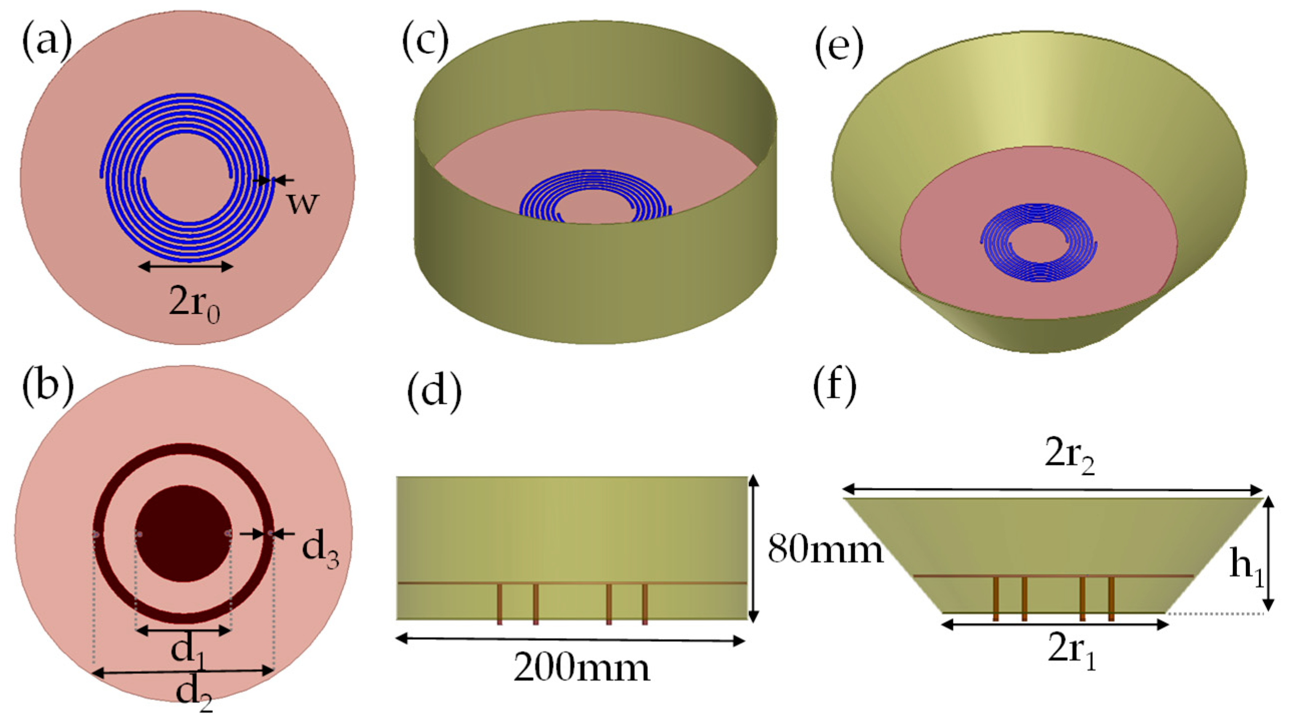
2.1. DASA Design

We designed a DASA to generate vortex EM waves carrying multiple OAM states. Figure 1a,b show the top and bottom views of the antenna, respectively. The antenna consists of a dual-arm Archimedean spiral on the top, two different disks at the bottom, and four 50 Ω coaxial feeding ports. The spiral antenna is printed on a 0.762 mm thick Rogers 4350 B substrate with a relative permittivity of 3.48 and a dielectric loss tangent of 0.0031. The inner radius of the spiral curve is r0 = 20 mm, and the arm width is w = 1.5 mm. The arm growth rate of the spiral is a = 0.93 mm/rad, and the number of turns is N = 3.5. The diameters of discs are d1 = 23 mm and d2 = 43 mm, respectively, and the width of the outer disk is d3 = 5 mm. Two discs, which are printed at the bottom of the substrate, are used for impedance matching. The inner and outer conductors of four coaxial cables are connected to the spiral and discs, respectively. The proposed antenna is modeled and analyzed using a home-built EM simulation program based on the finite element method.
The radiation of the DASA was analyzed using the theoretical model of a two-wire transmission line [28]. In the ideal case, the amplitude and phase of the current along the transmission line are constant and continuously changing, respectively. Radiation may take place in an annular ring where the currents in the adjacent arms are in-phase. In comparison to the traveling-wave circular loop antenna, the spiral antenna has a wide impedance bandwidth since its radiation region moves with a change in operating frequency [26]. In addition, the positive and negative OAM states will exist when the spiral is excited at the inner and outer ends, respectively, since the current flows in the two cases travel in opposite directions. Therefore, the dual-feeding method may generate the dual-mode OAM states with positive and negative topological charges at a single frequency, while a traditional spiral with single-feeding only generate one OAM mode at a single frequency. That is to say, the proposed antenna has potential applications in the RF OAM multiplexing system. Note that vortex waves can only be produced when the spiral antenna works at orders greater than one [26].
According to the theory [29], the radiation may take place in the annular ring, of which the radius is r, when the radius r satisfies
r = c ( | l | + 1 ) 2 π f
where c is the light speed, f is the working frequency, and l is the topological charge of the OAM mode to be generated. In our design, the inner and outer radii of the spiral are 20 and 40 mm, respectively. For f = 3 GHz, 4 GHz, and 4.8 GHz, it can be calculated that the antenna will radiate vortex beams with topological charges of |l| = 1, |l| = 2, and |l| = 3. The sign are positive and negative for feeding at the inner and outer ends, respectively.
To investigate the characteristics of the designed DASA, the phase distributions and intensities of the radiated electric field can be obtained in simulations. As shown in Figure 2a–c when fed at inner ends, the DASA radiates vortex beams with positive OAM states of l = 1, 2, and 3 at working frequencies of f = 3 GHz, 4 GHz, and 4.8 GHz, respectively. As shown in Figure 2d–f, feeding at outer ends, the DASA radiates vortex beams with negative OAM states of l = −1, −2, and −3 at f = 3 GHz, 4 GHz, and 4.8 GHz, respectively. It is apparent that the phase patterns have an anticlockwise and clockwise rotations with a 2π, 4π, and 6π phase changes at f = 3 GHz, 4 GHz, and 4.8 GHz, respectively. In addition, the intensities of the electric field exhibit doughnut shapes with nulls in the center. From these results, we can see the important characteristics of the vortex beams with different OAM states.

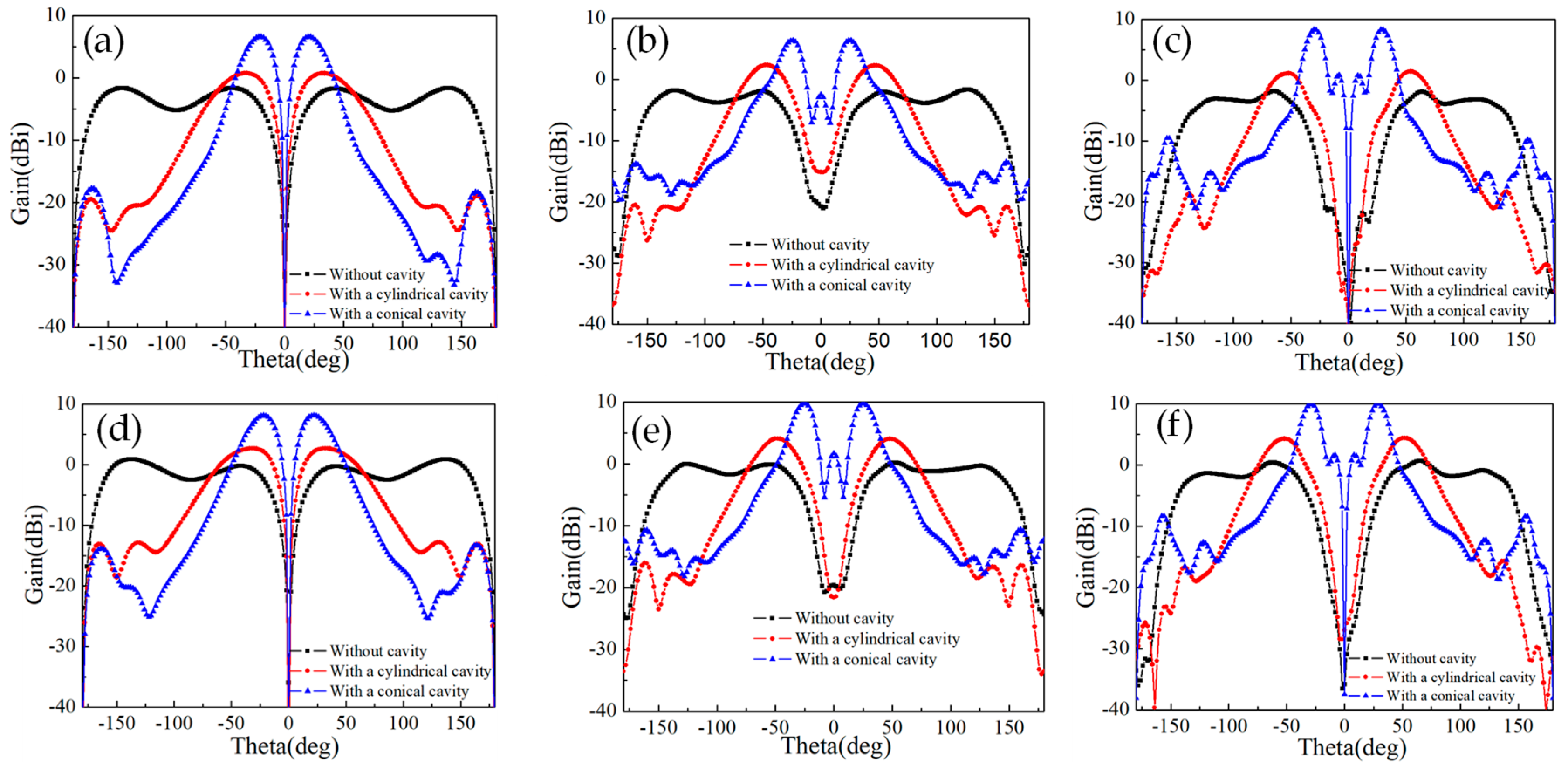
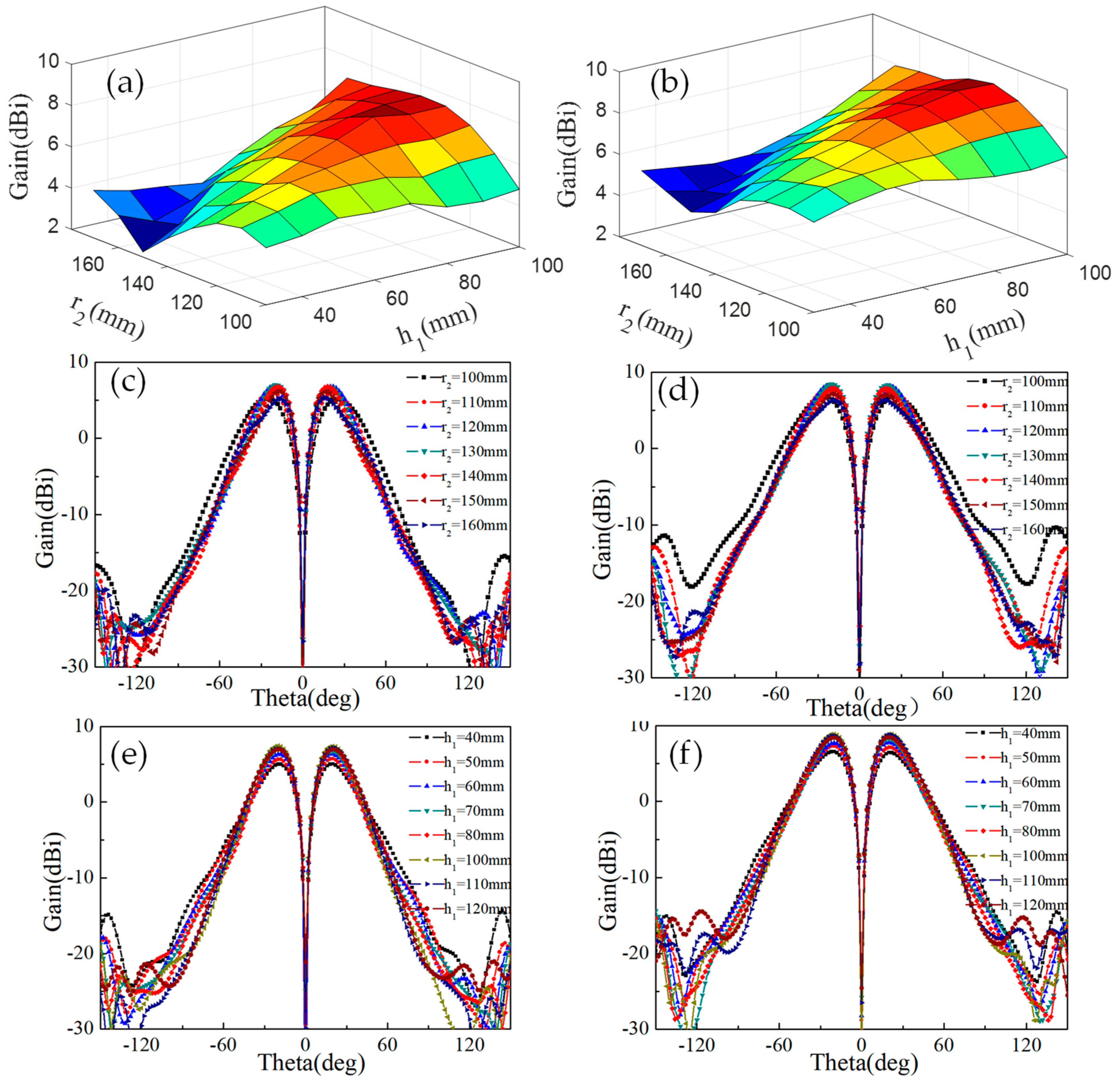
2.2. Optimization of DASA

Usually, the gains of planar antennas are relatively low, hindering their real applications. The black lines in Figure 3 plot the radiation patterns of the proposed plane DASA in the E plane at various topological charges of l = −1, −2, −3, +1, +2, and +3, presenting the characteristic of low gain. Therefore, a cavity could be added to the planar DASA to increase the gain due to the cavity resonance.
For enhancing the gains, a traditional cylindrical cavity is used, as shown in Figure 1c,d. The structure of the cylindrical cavity is optimized with a height of 80 mm and a radius of 100 mm. As a result, the gain of the DASA is enhanced by more than 2.5 dBi owing to the cavity resonance, as plotted by the red lines in Figure 3. However, the gains are not high enough, and the cavity needs to be optimized further.
Instead, a conical cavity is considered to be used outside the DASA, because EM waves are more effectively radiated by the tapered cavity to improve the directionality of the antenna. Figure 1e,f show the schematics of the DASA with a conical cavity from the 3D and cross-sectional views, respectively. To demonstrate the effectiveness, we calculate the radiation patterns of the corresponding vortex beam generated from the DASA with a conical cavity at each OAM mode. As shown by the blue lines in Figure 3, the gain of each OAM mode is significantly increased by more than 5 dBi when using a conical cavity in comparison to the cylindrical cavity case. In addition, divergence angles of the OAM beams also decrease for the DASA with a conical cavity. In the end, gains of the DASA are increased by the conical cavity almost equally for the same working frequency when fed at the inner and outer ends, demonstrating further the good performance of the proposed DASA to generate multiple OAM states.
To achieve a better performance of DASA, the radius r2 of the top aperture and the height h1 of this cavity are considered as optimized parameters. For brevity, we just present gain patterns at 3 GHz corresponding to l = ±1. As shown in Figure 4a,b, gains greatly vary with the different radii (r2) of the top aperture and height (h1) of this cavity. To obtain further details of the radiation patterns, comparison results of two sets of optimized parameters are presented in Figure 4c–f. Figure 4c,d show the effects of various radii r2 of the top aperture on the radiation patterns when the height h1 of the conical cavity is 70 mm. With an increasing r2, the gain increases and the direction angle θ of the main lobe decreases, which can be attributed to the enlarged radiation aperture with increasing r2, thereby improving the directionality of the proposed antenna. However, the gain decreases when r2 increases to 140 mm due to the increase of the side lobe by overlarge aperture. Figure 4e,f show the effects of various heights (h1) of the conical cavity on radiation patterns when the radius of top aperture is r2 = 130 mm. When h1 increases, the gain increases and the direction angle θ of the main lobe remains almost the same at l = ±1. Meanwhile, the gain decreases when h1 increases to 110 mm. This indicates that a higher height of the conical cavity in a certain range is more beneficial for focusing the EM power forward. In addition, the cases at l = ±2 and l = ±3 are similar to the case at l = ±1 except that the gain decreases when r2 increases to 130 mm at l = ±3.
To make the gain of each OAM mode as high as possible, based on the optimization above, the radii of the bottom and top aperture were set to r1 = 80 mm and r2 = 130 mm, respectively. Meanwhile, the height h1 of the cavity was chosen to be 80 mm by taking into account the enhanced gains at l = −1 and l = 1. Figure 5a plots the two-dimensional (2D) radiation patterns at l = −1, −2, and −3. The 2D radiation patterns at l = 1, 2, and 3 are presented as well in Figure 5b. The direction of the main lobe is off the boresight axis for all generated OAM modes and the direction angle increases with the increasing |l|, which are the radiation features of OAM beams. The maximum gain and direction of the main lobe are summarized in Table 1. Simulated reflection coefficients of four input ports of the proposed spiral antenna are shown in Figure 6. The values of reflection coefficients of four input ports are lower than −15 dB, indicating that the proposed antenna has good impedance performances when excited at both the inner and outer ends.
Table 1 summarizes the gains and direction angles of the main lobes corresponding to OAM states with topological charges of l = −1, −2, −3, 1, 2, and 3 radiated from the proposed DASA with a conical cavity. OAM beams are generated with gains and direction angles of the main lobes of 7.19 dBi, 20° at l = −1, 6.74 dBi, 24° at l = −2, 8.06 dBi, 26° at l = −3, 8.63 dBi, 20° at l = 1, 10 dBi, 24° at l = 2, and 9.81 dBi, 27° at l = 3, respectively. The gains are high enough, allowing the proposed antenna to work normally in practice at each mode.
As shown in Figure 7, the simulated radiation efficiencies are more than 70% from 2.5 to 5 GHz when the proposed antenna are excited at the inner and outer ends of the spiral, respectively. At the key working frequencies of 3 GHz, 4 GHz, and 4.8 GHz, the efficiencies are 83.2%, 83.75%, and 86.16%, respectively, for the inner excitation case, and 84.41%, 84.33%, and 86.32%, respectively, for the outer excitation case. In addition, it can be seen that the efficiencies for two feeding cases almost remain the same in the range of 2.5–5 GHz, which indicates that the proposed DASA can effectively generate multiple OAM states.

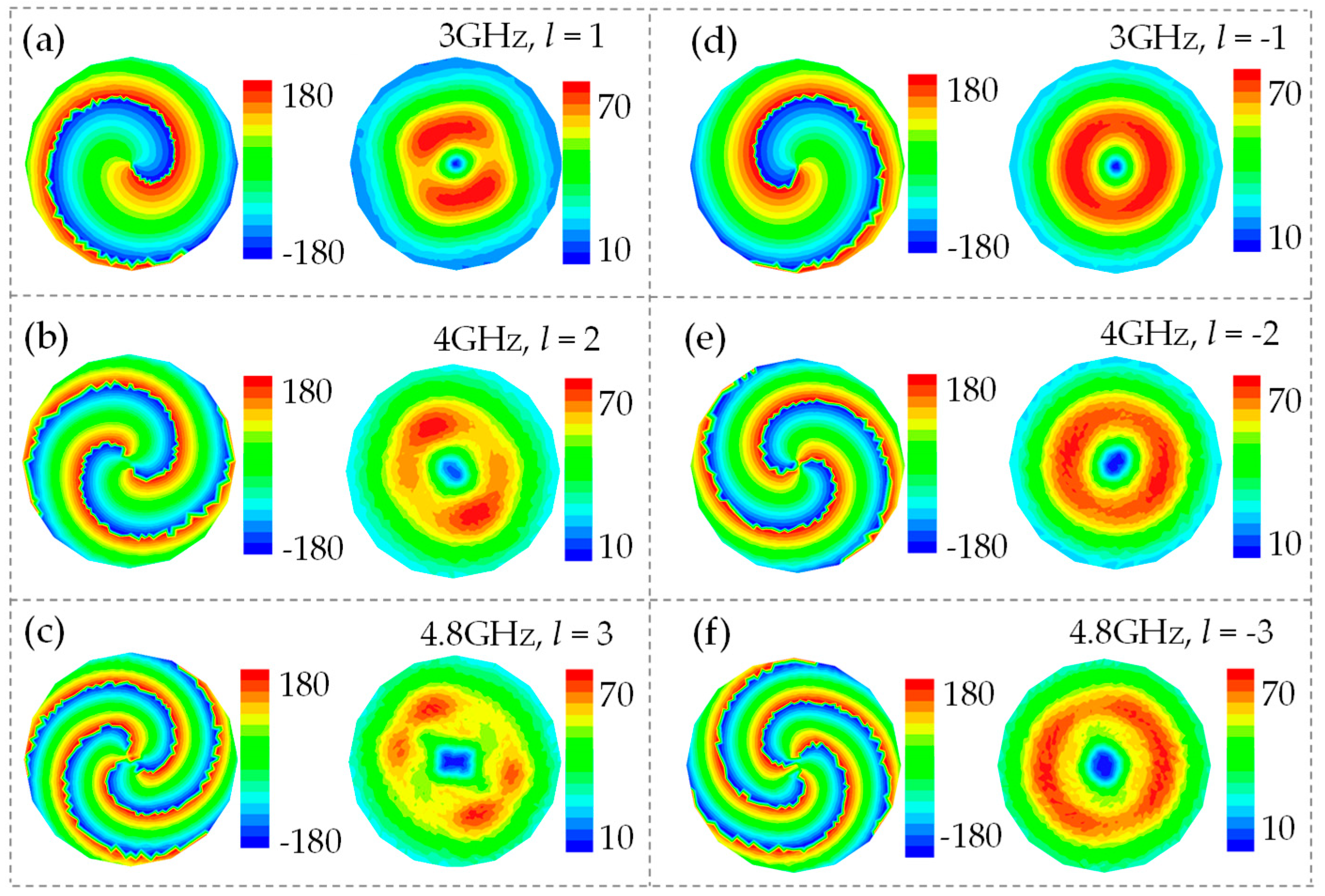
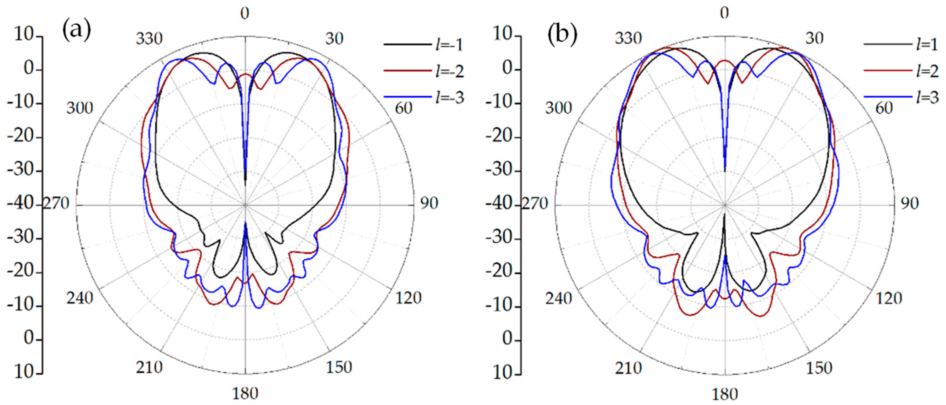
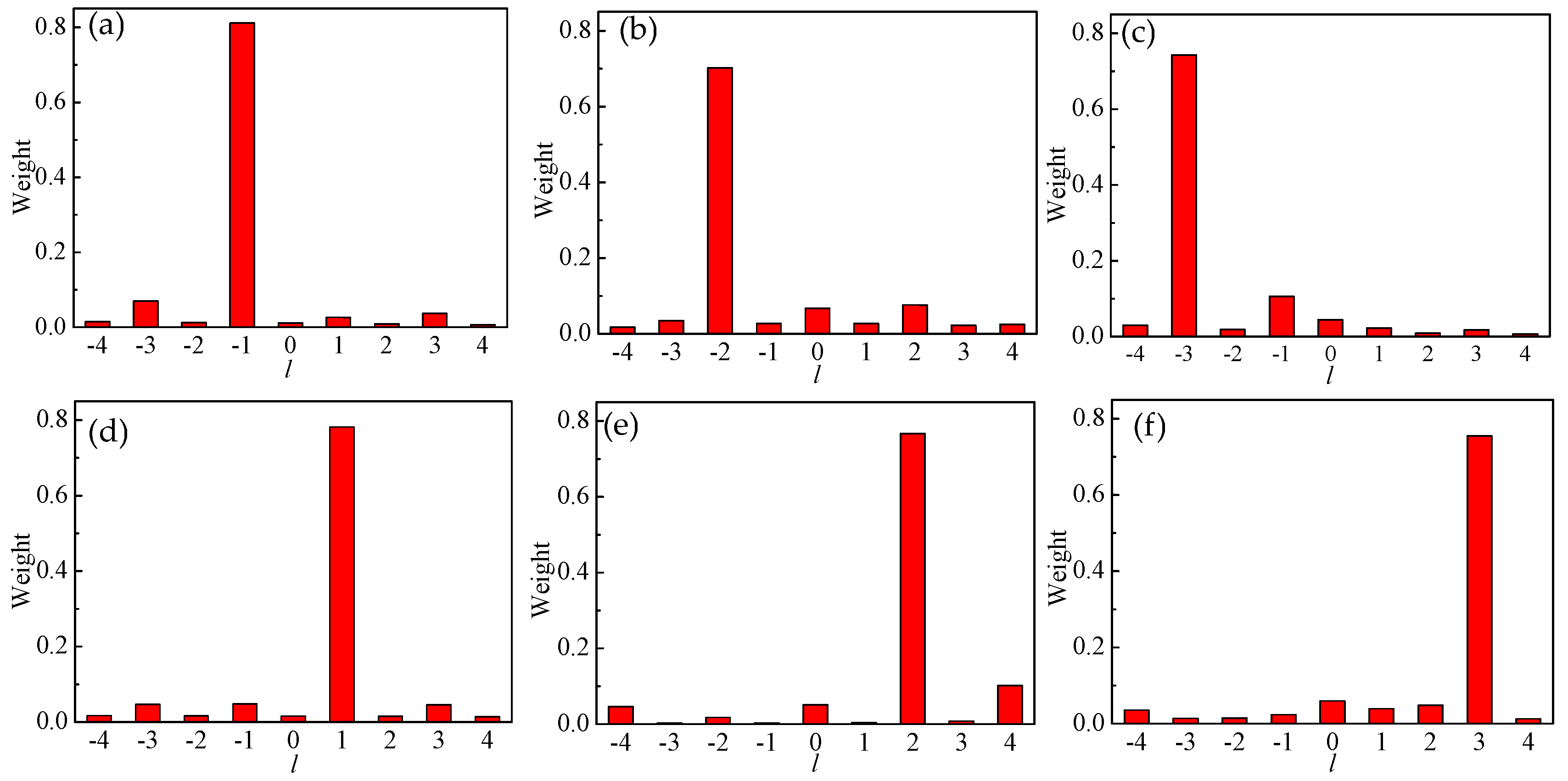
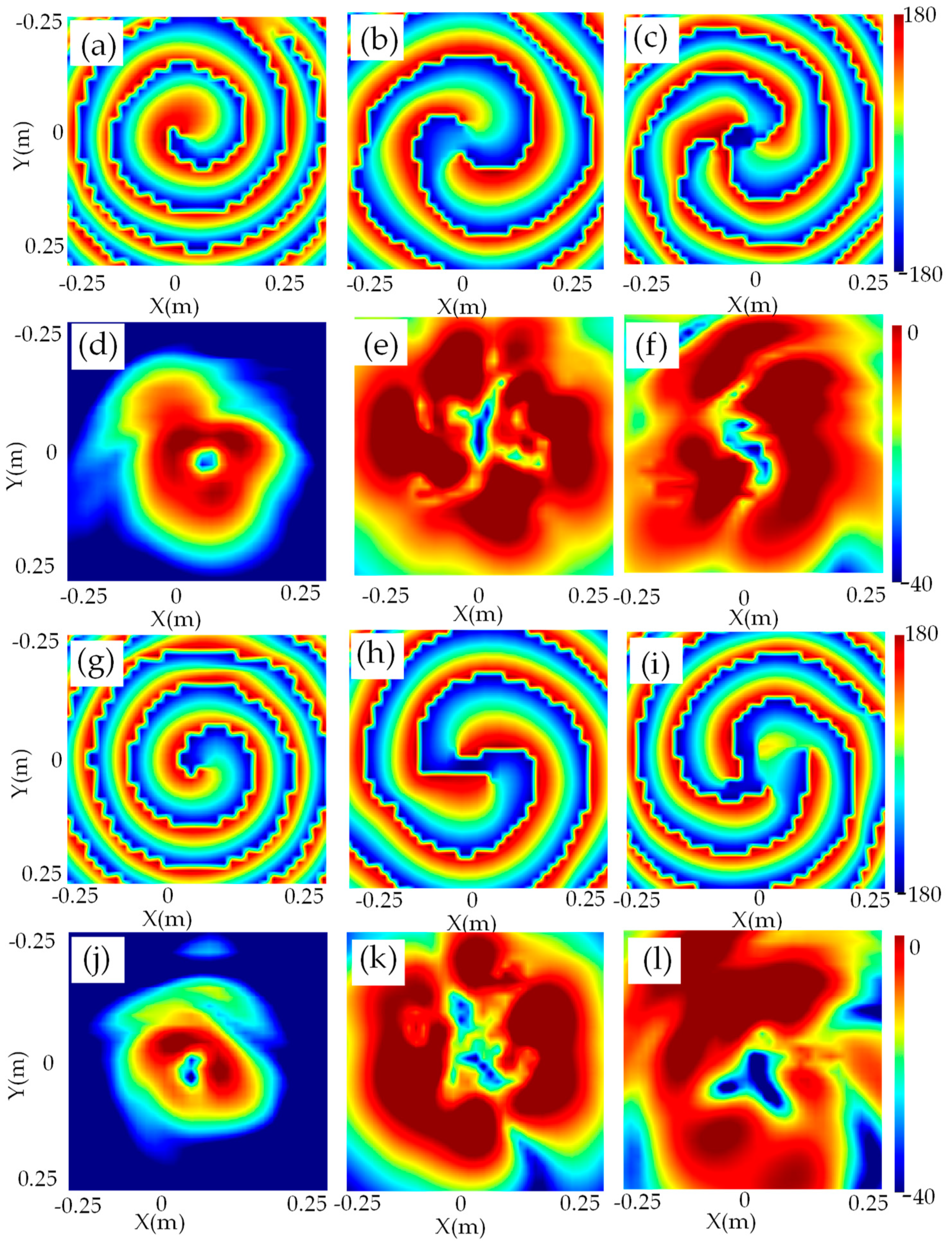
2.3. Purity Analysis

It is necessary to evaluate the quality of the radiated OAM beams since the distortion during generation and propagation of OAM beams may extend the OAM states to different topological charges. As is well known, the radiation field ψ is a function of radial angle θ and azimuthal angle φ. To analyze the purity of the OAM mode, ψ can be decomposed into the azimuth Fourier series:
ψ = l = A l e j l φ .
Al represents the weight of the lth OAM mode and can be obtained by integrating ψ with eilφ around φ:
A l = 1 2 π π π ψ ( φ ) e i l φ d φ .
Herein, the intensities and phases of the ring covered by the main lobe are extracted from the simulation results to calculate the OAM spectrum weight of each mode. The radiation field ψ is obtained on a ring where the intensities reach a maximum of the whole circle. The OAM modes are decomposed at frequencies of 3 GHz, 4 GHz, and 4.8 GHz. In these cases, the propagation distance of OAM beams is set to 140 mm, and the radius of observation surface is 200 mm. As shown in Figure 8a–f, although several side topological charges exist, the OAM spectrum weights of l = −1, −2, −3, 1, 2, and 3 are calculated to be 81%, 70%, 74%, 78%, 77%, and 75%, respectively. In other words, the targeted OAM modes dominate the spectrum. Thus, the proposed antenna radiates OAM beams with good mode purity characteristics.

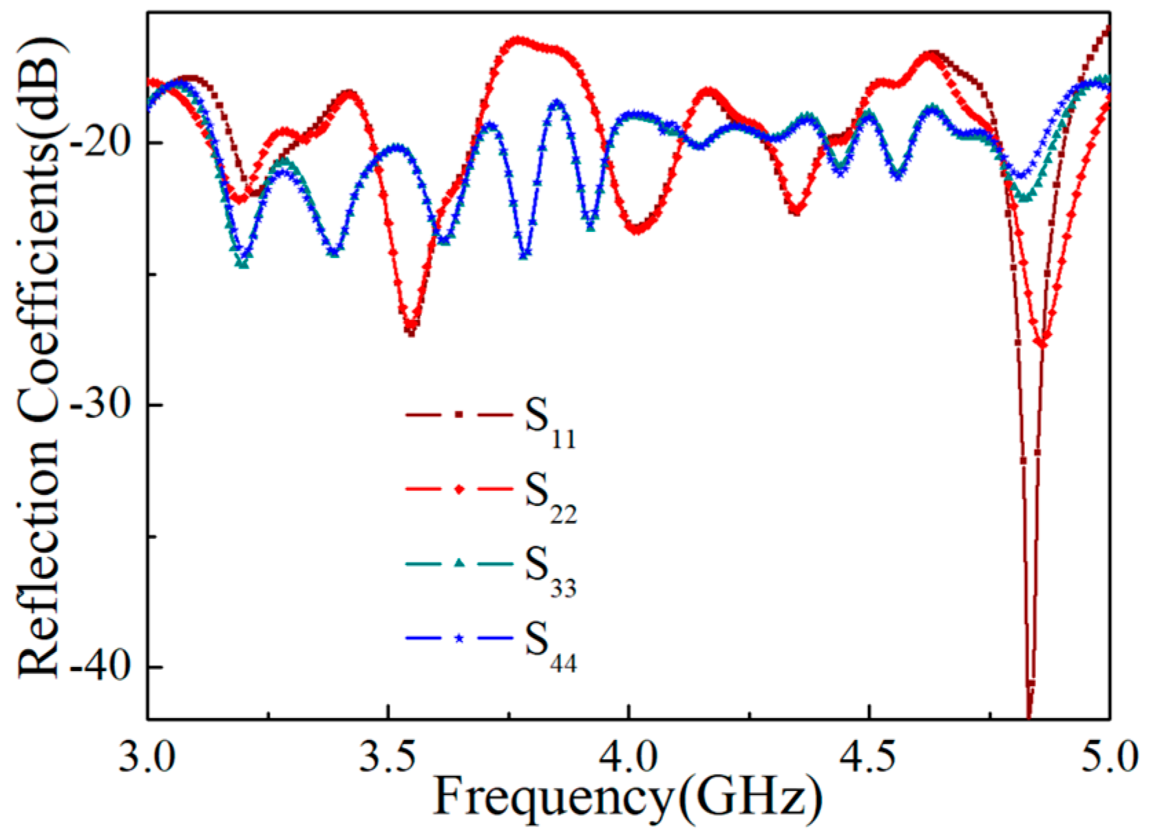
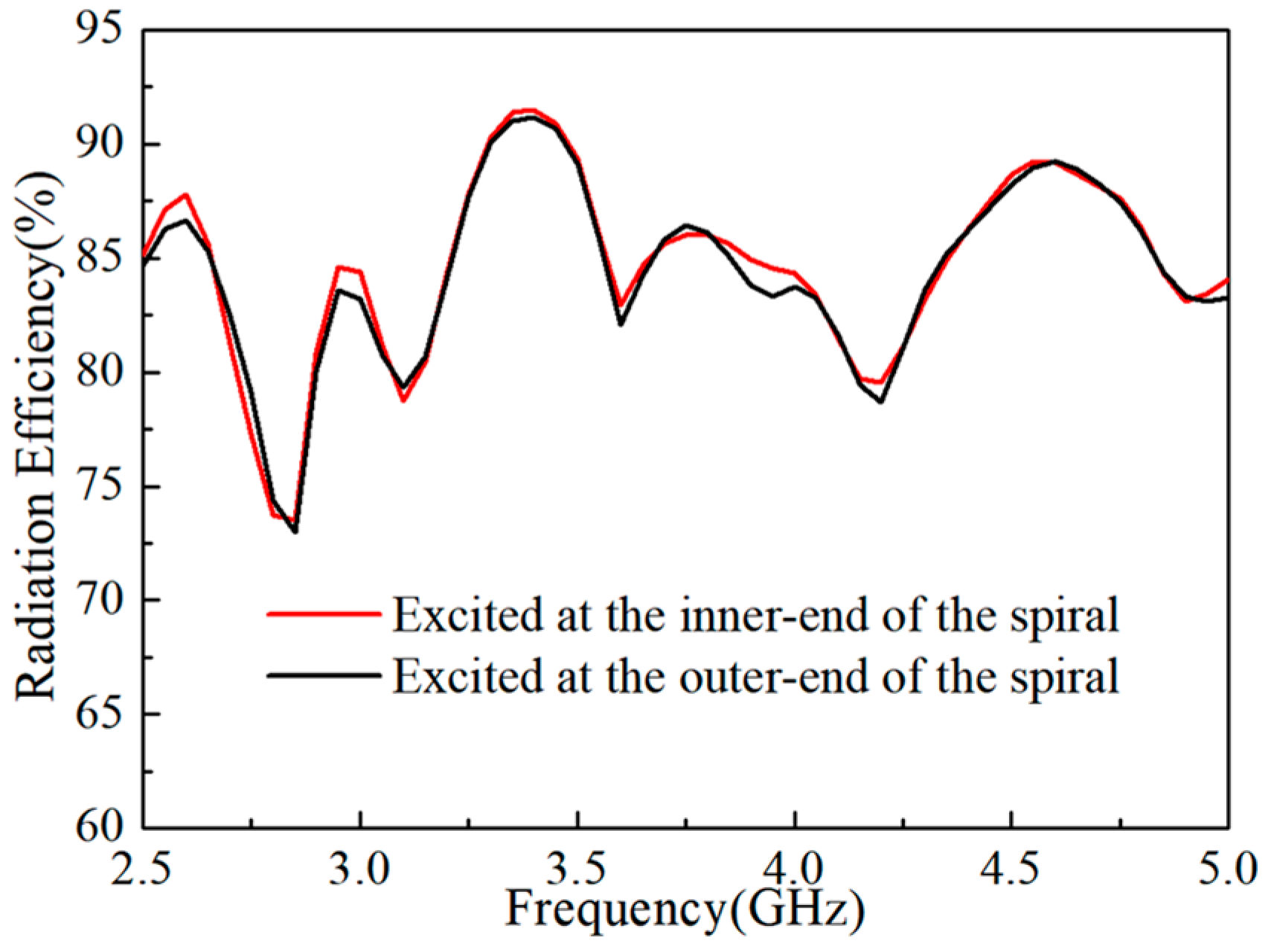
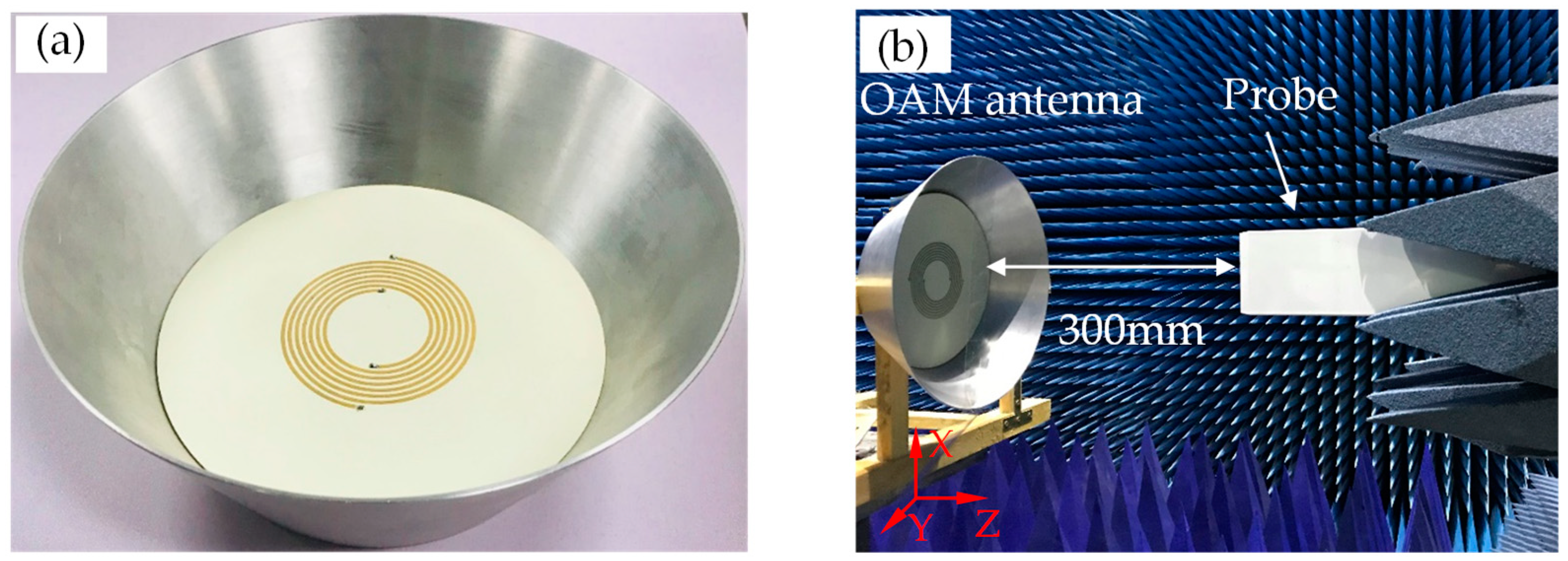
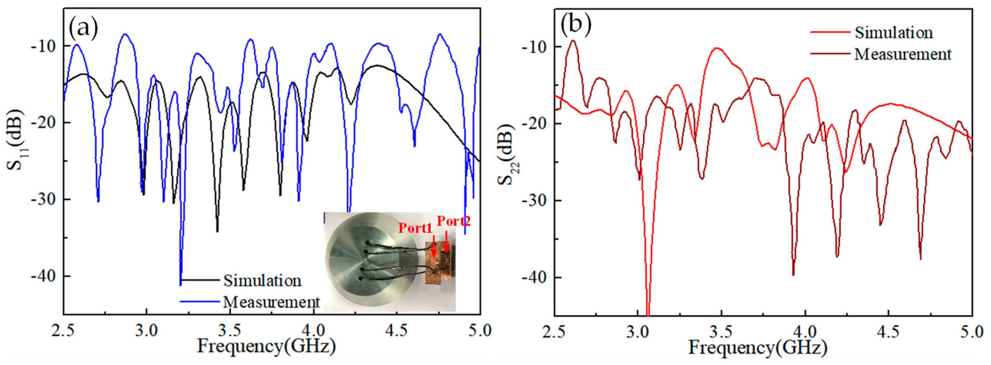
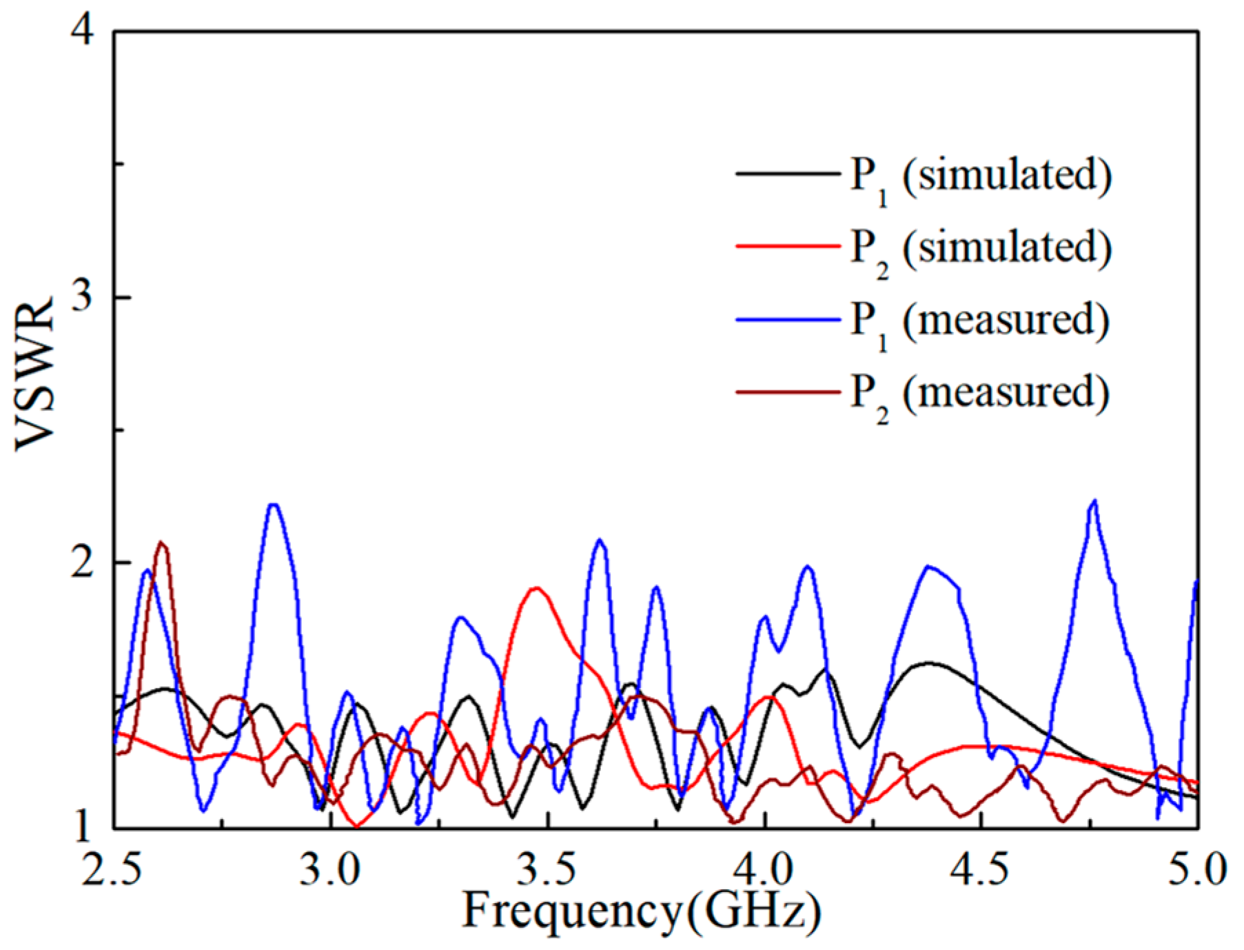
3. Fabrication and Measurement of the DASA

To verify the theoretical and simulated results of the proposed antenna, the antenna was fabricated and measured accordingly. The 3D view of the fabricated antenna is shown in Figure 9a. In order to measure the performance of the designed antenna further, the feeding ports of the inner end of the spiral are connected to the outputs of a two-way power divider whose amplitude and phase for the two outputs are the same. The feeding ports of the outer end of the spiral are connected to the outputs of two-way power splitters with a phase difference of 180 degrees between two outputs, which are shown in the inset of Figure 10a. The measurements were carried out with a vector network analyzer (VNA, Rohde & Schwarz, ZVA 40). Figure 11 shows that the measured and the simulated Voltage Standing Wave Ratio (VSWR) of the two ports were almost below 2 in the range of 2.5–5 GHz, which illustrates that the measured results are consistent with the simulated results as a whole. Figure 10a,b show that the simulated and measured reflection coefficients S11 of Port 1 and S22 of Port 2, respectively. The results show that the proposed antenna can almost cover a 2.5–5 GHz band. The deviation between the simulated and measured results can be attributed to the fabrication error and the measurement environment.
The electric field distributions were measured in an anechoic chamber and are presented in Figure 9b. In the experiment, the open waveguide is used as the near-field measurement detecting probe, as shown in Figure 9b. The main planes of the detecting probe and OAM antenna are parallel in the x–y plane with a distance of 300 mm along the z-axis. The size of the sampling plane is 500 × 500 mm, and the number of the sampling points is 36 × 36. As shown in Figure 12a–l, the normalized intensities and phase distributions of the electric field are measured in the sampling plane. The doughnut-shaped intensities and helical phase distributions can be observed at each OAM mode. The results demonstrate that the proposed antenna can radiate OAM vortex beams with l = ±1 at 3 GHz, l = ±2 at 4 GHz, and l = ±3 at 4.8 GHz, in which l = +1, +2, and +3 can be generated with the feeding point at the inner end as depicted in Figure 12a–f, and l = −1, −2, and −3 can be generated with the feeding point at the outer end as depicted in Figure 12g–l.
2D far field radiation patterns of the antenna are measured at 3 GHz for the mode of l = 1 (Figure 13a), 4 GHz for the mode l = 2 (Figure 13b), and 4.8 GHz for the mode l = 3 (Figure 13c). The measured and simulated results are in good agreement, which indicates that the proposed antenna has a superior radiation performance.
Table 2 presents a performance comparison of the proposed antenna with other recently reported OAM antennas. The antenna structure, center frequency, bandwidth, OAM modes, and gains are given. It is clear that the proposed antenna achieves multiple generated OAM modes over the wider bandwidth of 66.6%. Meanwhile, in comparison to array antennas [16,17,18,19], a single antenna to generate OAM modes is easier to design. In addition, the gain of the proposed antenna is higher than of that in [15] in terms of the single antenna structure for generating OAM vortex waves.

4. Conclusions

In conclusion, a DASA for the generation of multiple OAM modes is presented. To demonstrate, the DASA generates the OAM modes with topological charges of l = ±1, ±2, and ±3 at frequencies of 3 GHz, 4 GHz, and 4.8 GHz, respectively. In addition, a conical cavity is used to increase the gain of the DASA more than 5 dBi. The measured results show that the antenna can cover a 2.5–5 GHz band and multiple OAM modes can be generated effectively. Furthermore, OAM modes of the proposed DASA are decomposed at 3 GHz, 4 GHz, and 4.8 GHz. Each of the OAM mode purities is more than 70%, which is much dominant than those of other mode components. The numerical and experimental results show that the proposed antenna is a good candidate for applications in OAM communications and imaging techniques with the wide impedance bandwidth and high gain.

Author Contributions

Conceptualization, L.W.; methodology, K.G.; software, F.S.; formal analysis, L.W.; writing—original draft preparation, H.C.; writing—review and editing, Z.G.; supervision, Z.G.; funding acquisition, Z.G.

Funding

This research received no external funding.

Acknowledgments

This work was supported by the National Natural Science Foundation of China (61775050, 11804073, 61701159) and by the Fundamental Research Funds for the Central Universities (JZ2018HGBZ0309, JZ2018HGTB0240, JZ2018HGTB0236).

Conflicts of Interest

The authors declare no conflict of interest.

References

  1. Allen, L.; Beijersbergen, M.W.; Spreeuw, R.J.C.; Woerdman, J.P. Orbital angular momentum of light and the transformation of Laguerre-Gaussian laser modes. Phys. Rev. A 1992, 45, 8185. [Google Scholar] [CrossRef] [PubMed]
  2. Zhu, L.; Guo, Z.; Xu, Q.; Zhang, J.; Zhang, A.; Wang, W.; Liu, Y.; Li, Y.; Wang, X.; Qu, S. Calculating the torque of the optical vortex tweezer to the ellipsoidal micro-particles. Opt. Commun. 2015, 354, 34–39. [Google Scholar] [CrossRef]
  3. Kai, C.; Feng, Z.; Dedo, M.I.; Huang, P.; Guo, K.; Shen, F.; Gao, J.; Guo, Z. The performances of different OAM encoding systems. Opt. Commun. 2019, 430, 151–157. [Google Scholar] [CrossRef]
  4. Guo, Z.; Zhu, L.; Guo, K.; Shen, F.; Yin, Z. High-Order Dielectric Metasurfaces for High-Efficiency Polarization Beam Splitters and Optical Vortex Generators. Nanoscale Res. Lett. 2017, 12, 512. [Google Scholar] [CrossRef] [PubMed]
  5. Thidé, B.; Then, H.; Sjöholm, J.; Palmer, K.; Bergman, J.; Carozzi, T.D.; Istomin, Y.N.; Ibragimov, N.H.; Khamitova, R. Utilization of photon orbital angular momentum in the low-frequency radio domain. Phys. Rev. Lett. 2007, 99, 087701. [Google Scholar] [CrossRef] [PubMed]
  6. Zhang, D.; Cao, X.; Yang, H.; Gao, J. Radiation performance synthesis for OAM vortex wave generated by reflective metasurface. IEEE Access 2018, 6, 28691–28701. [Google Scholar] [CrossRef]
  7. Kai, C.; Huang, P.; Shen, F.; Zhou, H.; Guo, Z. Orbital Angular Momentum Shift Keying Based Optical Communication System. IEEE Photonics J. 2017, 9, 1–10. [Google Scholar] [CrossRef]
  8. Gaffoglio, R.; Cagliero, A.; Vecchi, G.; Andriulli, F.P. Vortex Waves and Channel Capacity: Hopes and Reality. IEEE Access 2018, 6, 19814–19822. [Google Scholar] [CrossRef] [Green Version]
  9. Yuan, T.; Wang, H.; Cheng, Y.; Qin, Y. Electromagnetic Vortex-Based Radar Imaging Using a Single Receiving Antenna: Theory and Experimental Results. Sensors 2017, 17, 630. [Google Scholar] [CrossRef]
  10. Turnbull, G.A.; Robertson, D.A.; Smith, G.M.; Allen, L.; Padgett, M.J. The generation of free-space Laguerre-Gaussian modes at millimetre-wave frequencies by use of a spiral phase plate. Opt. Commun. 1996, 127, 183–188. [Google Scholar] [CrossRef]
  11. Hui, X.; Zheng, S.; Hu, Y.; Xu, C.; Jin, X.; Chi, H.; Zhang, X. Ultralow reflectivity spiral phase plate for generation of millimeter-wave OAM beam. IEEE Antennas Wirel. Propag. Lett. 2015, 14, 966–969. [Google Scholar] [CrossRef]
  12. Tamburini, F.; Mari, E.; Sponselli, A.; Romanato, F.; Bo, T.; Bianchini, A.; Palmieri, L.; Someda, C.G. Encoding many channels in the same frequency through radio vorticity: first experimental test. New J. Phys. 2012, 14, 78001–78004. [Google Scholar]
  13. Barbuto, M.; Trotta, F.; Bilotti, F.; Toscano, A. Circular Polarized Patch Antenna Generating Orbital Angular Momentum. Prog. Electromagn. Res. 2014, 148, 23–30. [Google Scholar] [CrossRef]
  14. Zhang, Z.; Xiao, S.; Li, Y.; Wang, B.Z. A Circularly Polarized Multimode Patch Antenna for the Generation of Multiple Orbital Angular Momentum Modes. IEEE Antennas Wirel. Propag. Lett. 2017, 16, 521–524. [Google Scholar] [CrossRef]
  15. Zhang, Z.; Zheng, S.; Jin, X.; Chi, H.; Zhang, X. Generation of plane spiral OAM waves using traveling-wave circular slot antenna. IEEE Antennas Wirel. Propag. Lett. 2017, 16, 8–11. [Google Scholar] [CrossRef]
  16. Bai, X.D.; Liang, X.L.; Sun, Y.T.; Hu, P.C.; Yao, Y.; Wang, K.; Geng, J.P.; Jin, R.H. Experimental Array for Generating Dual Circularly-Polarized Dual-Mode OAM Radio Beams. Sci. Rep. 2017, 7, 40099. [Google Scholar] [CrossRef] [PubMed] [Green Version]
  17. Li, H.; Kang, L.; Wei, F.; Cai, Y.M.; Yin, Y.Z. A low-profile dual-polarized microstrip antenna array for dual-mode OAM applications. IEEE Antennas Wirel. Propag. Lett. 2017, 16, 3022–3025. [Google Scholar] [CrossRef]
  18. Liu, B.Y.; Cui, Y.H.; Li, R. A Broadband Dual-Polarized Dual-OAM-Mode Antenna Array for OAM Communication. IEEE Antennas Wirel. Propag. Lett. 2017, 16, 744–747. [Google Scholar] [CrossRef]
  19. Li, L.; Zhou, X. Mechanically Reconfigurable Single-Arm Spiral Antenna Array for Generation of Broadband Circularly Polarized Orbital Angular Momentum Vortex Waves. Sci. Rep. 2018, 8, 5128. [Google Scholar] [CrossRef]
  20. Wei, D.J.; Li, J.Y.; Yang, J.J. The vortical radio waves realized by helical antennas. In Proceedings of the 2017 IEEE International Symposium on Antennas and Propagation and Usnc/ursi National Radio Science Meeting, San Diego, CA, USA, 9–14 July 2017; pp. 175–176. [Google Scholar]
  21. Zhang, J.; Guo, Z.; Li, R.; Wang, W.; Zhang, A.; Liu, J.; Qu, S.; Gao, J. Circular polarization analyzer based on the combined coaxial Archimedes’ spiral structure. Plasmonics 2015, 10, 1255–1261. [Google Scholar] [CrossRef]
  22. Zhang, J.; Guo, Z.; Zhou, K.; Ran, L.; Zhu, L.; Wang, W.; Sun, Y.; Shen, F.; Gao, J.; Liu, S. Circular polarization analyzer based on an Archimedean nano-pinholes array. Opt. Express. 2015, 23, 30523–30531. [Google Scholar] [CrossRef] [PubMed]
  23. Guo, Z.; Li, Z.; Zhang, J.; Guo, K.; Shen, F.; Zhou, Q.; Zhou, H. Review of the functions of Archimedes’ spiral metallic nanostructures. Nanomaterials 2017, 7, 405. [Google Scholar]
  24. Rahman, M.; NaghshvarianJahromi, M.; Mirjavadi, S.; Hamouda, A. Bandwidth Enhancement and Frequency Scanning Array Antenna Using Novel UWB Filter Integration Technique for OFDM UWB Radar Applications in Wireless Vital Signs Monitoring. Sensors 2018, 18, 3155. [Google Scholar] [CrossRef] [PubMed]
  25. Rahman, M.; NaghshvarianJahromi, M.; Mirjavadi, S.; Hamouda, A. Resonator Based Switching Technique between Ultra Wide Band (UWB) and Single/Dual Continuously Tunable-Notch Behaviors in UWB Radar for Wireless Vital Signs Monitoring. Sensors 2018, 18, 3330. [Google Scholar] [CrossRef] [PubMed]
  26. Mao, F.; Huang, M.; Li, T.; Zhang, J.; Yang, C. Broadband generation of orbital angular momentum carrying beams in RF regimes. Prog. Electromagn. Res. 2017, 160, 19–27. [Google Scholar] [CrossRef]
  27. Nakano, H.; Satake, R.; Yamauchi, J. Extremely Low-Profile, Single-Arm, Wideband Spiral Antenna Radiating a Circularly Polarized Wave. IEEE Trans. Antennas Propag. 2010, 58, 1511–1520. [Google Scholar] [CrossRef]
  28. Kaiser, J. The Archimedean two-wire spiral antenna. IEEE Trans. Antennas Propag. 1960, 8, 312–323. [Google Scholar] [CrossRef]
  29. Johnson, R.C.; Jasik, H. Frequency-Independent Antennas. In Antenna Engineering Handbook, 3rd ed.; McGraw-Hill Book Company: New York, NY, USA, 1993; pp. 1–10. [Google Scholar]
Figure 1. Configuration of the proposed dual-arm Archimedean spiral antenna (DASA). (a) Top and (b) bottom views of the planar DASA; (c) 3D and (d) cross-sectional view of the proposed DASA with a cylindrical cavity; (e) 3D and (f) cross-sectional view of the proposed DASA with a conical cavity.
Electronics 08 00251 g001
Figure 2. Simulated results of phase distributions and intensities of the electric field: (ac) with topological charges of l = 1 at 3 GHz, l =2 at 4 GHz, and l = 3 at 4.8 GHz, respectively, when fed at inner arm ends; (df) with topological charges of l = −1 at 3 GHz, l = −2 at 4GHz, and l = −3 at 4.8 GHz, respectively, when fed at outer arm ends.
Electronics 08 00251 g002
Figure 3. Comparison results of radiation patterns in the E plane without cavity, with a cylindrical cavity, and with a conical cavity at (a) l = −1, (b) l = −2, (c) l = −3, (d) l = 1, (e) l = 2, and (f) l = 3.
Electronics 08 00251 g003
Figure 4. Comparison results of gains at (a) l = −1 and (b) l = 1 with various r2 and h1. Gain patterns in the E plane at (c) l = −1 and (d) l = 1 with different r2, (e) l = −1 and (f) l = 1 with different h1.
Electronics 08 00251 g004
Figure 5. Far-field radiation patterns at (a) l = −1, −2, and −3 and (b) l = 1, 2, and 3.
Electronics 08 00251 g005
Figure 6. The reflection coefficients of the proposed antenna.
Electronics 08 00251 g006
Figure 7. The radiation efficiencies of the proposed antenna.
Electronics 08 00251 g007
Figure 8. Histograms of orbital angular momentum (OAM) spectrum weight. (a) l = −1, (b) l = −2, (c) l = −3, (d) l = 1, (e) l = 2, and (f) l = 3.
Electronics 08 00251 g008
Figure 9. (a) The 3D view of the fabricated antenna; (b) the experiment system configuration.
Electronics 08 00251 g009
Figure 10. The simulated and measured (a) S11 and (b) S22 of the proposed antenna.
Electronics 08 00251 g010
Figure 11. The simulated and measured Voltage Standing Wave Ratio (VSWR) of the proposed antenna.
Electronics 08 00251 g011
Figure 12. Measured phases (ac) and intensities (df) distributions of generated OAM electric field with topological charges of l = 1 at 3 GHz, l = 2 at 4 GHz, and l = 3 at 4.8 GHz, respectively, when fed at the inner end; and the phases (gi) and intensities (jl) distributions generated topological charges of l = −1 at 3 GHz, l = −2 at 4 GHz, and l = −3 at 4.8 GHz, respectively, when fed at the outer end.
Electronics 08 00251 g012
Figure 13. The simulated and measured radiation patterns of the proposed antenna at (a) 3 GHz, (b) 4 GHz, and (c) 4.8 GHz
Electronics 08 00251 g013
Table 1. The gain and direction angle of the main lobe with a conical cavity. OAM: orbital angular momentum.
OAM ModeGain (dBi)Direction Angle (deg)
−17.1920
−26.7424
−38.0626
18.6320
21024
39.8127
Table 2. Performance comparison with reported OAM antennas.
ReferencesAntenna Structuref0 (GHz)BandwidthOAM ModesGain (dBi)
[14]Concentric patches5.65Narrow1,−2N.A
[15]Cavity+ slot+ Horn10Narrow2,3,43.71
[16]Stacked MP 4 array4.830%1,−19
[17]* MP 4 array5.5Narrow1,−19.5,10.2
[18]* MP 4 array2.425%1,−1N.A
[19]* MP 8 array4.0525%1,2,3N.A
Proposed antenna* MP + cavity3.7566.6%1,2,3,−1,−2,−36.7–10
* MP: microstrip-patch.

