Article

Robust Control of Heterogeneous Vehicular Platoon with Non-Ideal Communication

1
School of Automotive Engineering, Chongqing University, Chongqing 400044, China
2
Mechanical Engineering, University of Michigan, Ann Arbor, MI 48109, USA
*
Author to whom correspondence should be addressed.
Electronics 2019, 8(2), 207; https://doi.org/10.3390/electronics8020207
Submission received: 5 November 2018 / Revised: 21 January 2019 / Accepted: 29 January 2019 / Published: 12 February 2019

Abstract

:
The application of wireless communication to platooning brings such challenges as information delay and varieties of interaction topologies. To compensate for the information delay, a state predictor based control strategy is proposed, which transmits the future information of nodes instead of current values. Based on the closed loop dynamics of platoon with state predictor and feedback controller, a decoupling strategy is presented to analysis and design the platoon control system with lower order by adopting the eigenvalue decomposition of topological matrix. A numerical method based on LMI (Linear Matrix Inequality) is provided to find the required robust performance controller. Moreover, the influence of information delay on performance is studied theoretically and it is found that the tolerable maximum delay is determined by the maximum topological eigenvalue. The effectiveness of the proposed strategy is validated by several comparative simulations under various conditions with other methods.

1. Introduction

The problem of traffic congestion, safety and pollution is getting increasingly serious [1]. Worldwide researchers, companies and governments are devoted to solving these issues and one of these technologies is called platooning, that is, a coordinated motion of a group of vehicles with the same destination and speed (referring to the leader) [2,3]. By this way, the air drag is reduced greatly, meanwhile the traffic flow is increased due to the smaller car-following distance. Many demo projects have already been carried out, for example, the Konvoi project in Germany [4], the founding of the California Partners for Advanced Transit and Highways program in USA [5], the Energy Intelligent Transport Systems project in Japan [6]. With these efforts, many challenges on practical application have been studied and overcome, such as vehicle dynamic control [7,8], vehicle-to-vehicle (V2V) communication [9,10], platoon controller design [11,12] and spacing policies [13].
Over the past 30 years, wireless communication has experienced rapid development, meanwhile lots of new V2V technologies appear, for example, vehicular ad-hoc network and dedicated short range communication [14,15]. Besides such assistance systems as collision warning at intersection, V2V has also been applied to platooning, which brings the benefit of better performances but leads to varieties of information topologies, for example, the bidirectional type (BD), two-predecessors following type (TPF), predecessor-leader following type (PLF) and so forth. [11,12]. Moreover compared with earlier radar-based system, V2V inevitably introduces other issues like information delay, packet dropout and so forth. From the previous studies, it is known that delay will cause platoon to be degraded and even string instable [16].
To achieve better performances, many advanced control approaches have been applied, such as linear state feedback control [17], optimal control [18], sliding mode control [19] and model predictive control, which require the information topology to be known in advance and unchanged [20]. When V2V is adopted, the topology becomes uncertain because of the environmental degradation of communication, which combined with information delay poses great challenges on platoon control system design. One way is to consider the behavior of platoon as a multi-agent system and the varieties of topologies is uniformly described by the graph theory. In particular, it is known that the consensus control performance is influenced by the Laplacian matrix [21,22]. Based on this approach, Zheng et al. studied the stability of homogeneous platoon based on the Routh–Hurwitz theory [23]. Moreover to deal with the uniform delay, Peters et al. provided a general linear control method [24] and Gong et al. established a newly sampled-data control method [25]. Both of them guarantee the string stability of homogeneous platoon with PLF. Gao et al. further presented an H control method for heterogeneous platoon to ensure robust stability, string stability and tracking ability simultaneously [26]. Considering heterogeneous delay, Bernardo et al. designed a distributed controller by treating it as a consensus issue [27]. This strategy maintains a stable platoon but the referenced velocity is constant and only PLF is applicable. Besides these advanced methods dealing with communication delay, some new wireless communication technologies, such as future 5G and LTE-V2X, have been studied and demonstrated to enhance communication itself [28,29]. These new technologies reduce the delay to a negligible level but today IEEE 802.11p and its related standard are already available [30].
The aforementioned work mostly focuses on one of the difficulties caused by V2V, that is, the topological uncertainties and heterogeneous communication delay. Consequently, the primary objective and main contribution of this paper are: 1) To deal with heterogeneous communication delay, a state predictor is designed to transmit future information of next sampling so that the negative effect of delay is compensated for. 2) Considering the topological uncertainty, eigenvalue decomposition of topological matrix and linear transformation are applied to decouple the platoon into multiple systems with lower order. 3) Based on the Lyapunov stability theory, a numerical way is presented to numerically solve a robust state feedback controller by LMI (Linear Matrix Inequality).
The reminder of paper is organized as follows: Section 2 introduces the studied problems and the closed-loop dynamics of the vehicular platoon is established in Section 3. Section 4 presents the decoupling design strategy and the theoretical analysis is conducted in Section 5. Comparative simulations are demonstrated in Section 6 and Section 7 concludes the paper.

2. Problem Description

2.1. Notations and Definitions

Let m × n be the set composed of real matrix with dimension m × n , 0 denote the matrix with all entries being zero, I N N × N be the identity matrix and 1 N N be the vector with all entries being 1. Notion · 2 is the L 2 norm of signal and its induced norm is · , the superscript “ T ” represents the transposition of matrix, “*” denotes the symmetric part in one matrix, “ ” represent the Kronecker product,   σ ( X ) is the singular value of X , among which σ ¯ ( X ) and σ _ ( X ) are the maximum and minimum one respectively.

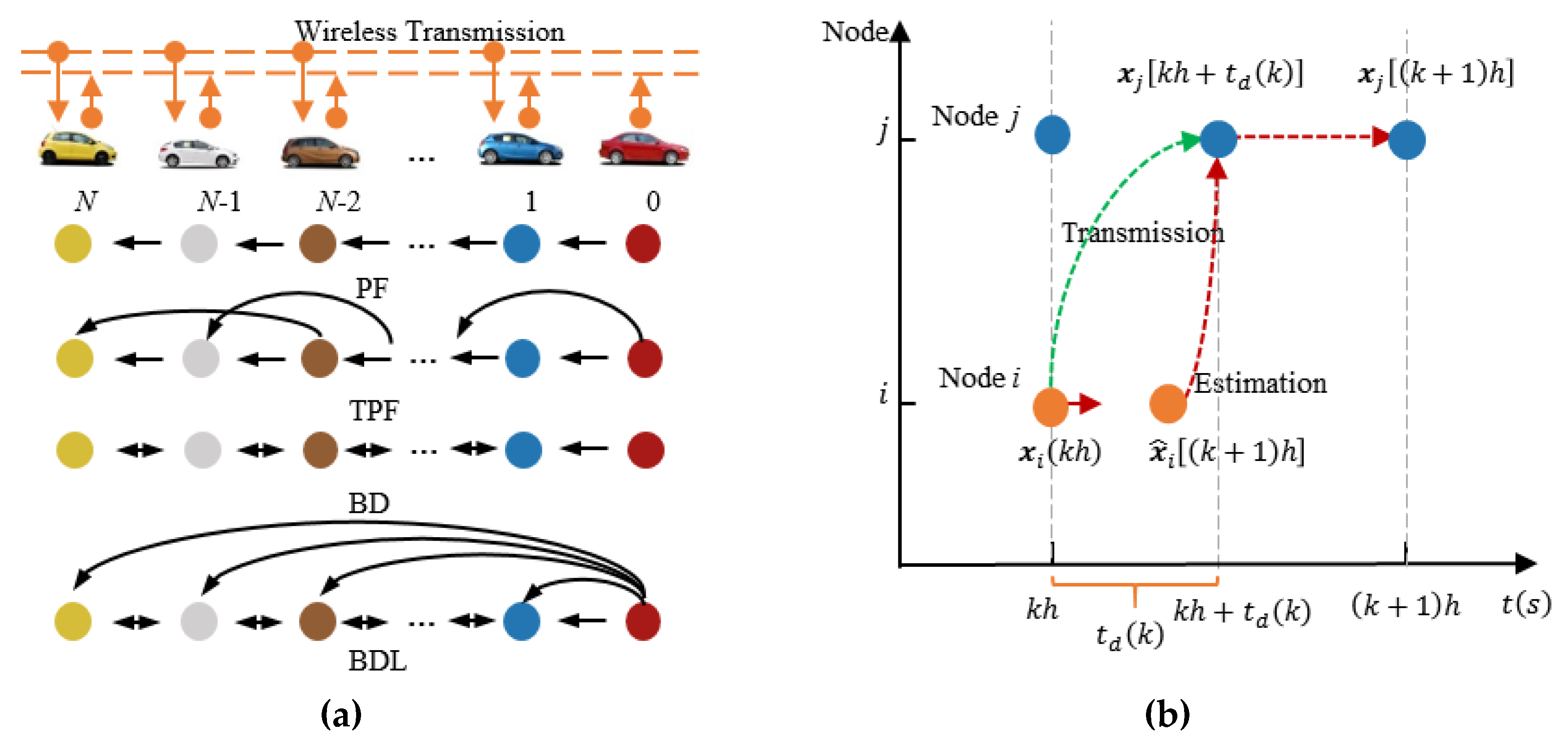
2.2. Problem Analysis Caused by V2V

As shown in Figure 1a, the studied platoon consists of N + 1 heterogeneous vehicles, that is, N followers (Indexed by 1 , , N ) and one leader (Indexed by 0) sharing their state by V2V.
Because of the degradation of V2V, two issues arise naturally: (1) Uncertainties of topology caused by change of communication range and so forth. (See Figure 1a); (2) Information delay influenced by environments and distances. Figure 1b gives an example of the delay between two nodes, where node j is assumed to receive the state x i ( k h ) of node i , h is the sampling period and the delay is t d ( k ) . At the ( k + 1 ) -th sample, node j calculates its control with the state x i ( k h ) at k -th sampling of node i , which introduces a time delay in the closed loop dynamics and is bad to control performances. As indicated by red line in Figure 1b, if all nodes transmit their predicted state at the future, such information delay can be reduced and even eliminated completely when the sampling time is known. Motivated by this idea and considering the fact that such global clock as GPS (Global Position System) can be used to synchronize the control period of platoon [16], a state predictor based platoon control system is proposed as shown in Figure 2, where K is the state feedback to be designed in Section 4.2. With this control strategy, all nodes transmit their predicted state at next sampling and control themselves by a predefined control cycle to compensate for the information delay. The topology uncertainty will be dealt with in Section 4 based on the closed loop dynamics of this predictor based platoon control system.

3. Closed-Loop Dynamical Model of Platoon

3.1. Vehicle Dynamical Model

Though the original vehicle dynamics is nonlinear, referring to [11,23,26] the following linear format is used to describe the dynamics of vehicle node, whose nonlinearities and environmental disturbances are compensated for by a lower dynamical controller [8]:
x i ( k + 1 ) = A i x i ( k ) + B i u i ( k ) ,       i = 0 , , N ,
where A i and B i are the state and control matrices respectively, k denotes the sampling time, u i ( k )   is the control input, x i ( k ) = [ p i ( k ) v i ( k ) a i ( k ) ] T where p i ( k ) ,     v i ( k ) and a i ( k ) are the position, velocity and acceleration of node i . Note that the studied platoon is heterogeneous, that is, A 0 A N and B 0 B N but each vehicle known its own parameters. According to the control strategy shown by Figure 2 and (1), the state predictor is designed to be
  x ^ i ( k + 1 ) = A i x i ( k ) + B i u i ( k ) ,   i = 0 , , N ,
where x ^ i ( k ) is the predicted state. Note that being different from followers controlled by the designed state-feedback controller, leader receives the command from others, such as driver or traffic management system whose dynamical characteristics are unknown.

3.2. Topology of Information Flow

To generate a unified description of varieties of topologies, the graph theory is used to model as a directed graph G = ( V , E ) , where V = { 1 , , N } denotes the set of nodes and E V × V indicates the set of edges [23]. The adjacency matrix Z = [ z i j ] N × N indicates the connections among followers:
{ z i j = 1 ,       i f   { j , i } E z i j = 0 ,       i f   { j , i } E       i , j = 1 , , N ,
where { j , i } E means there exists a directional edge from node j to i , that is, vehicle i can receive information from j and there is no self-loop, that is, z i i = 0 . Base on Z , the Laplacian matrix L = [ l i j ] N × N associated with G is
l i j = { j = 1 N z i j ,                   i = j z i j ,                       i j ,
The connectivity between leader and followers is described by the pinning matrix P = diag { p 1 , p 2 , , p N } , where p i = 1 if node i receives information from leader, otherwise p i = 0 . Combined the above definitions, the topological matrix for information flow is G = L + P . Note that to keep the formation each follower has a direct or indirect connection with leader, which makes all eigenvalues of G be greater than zero [26].

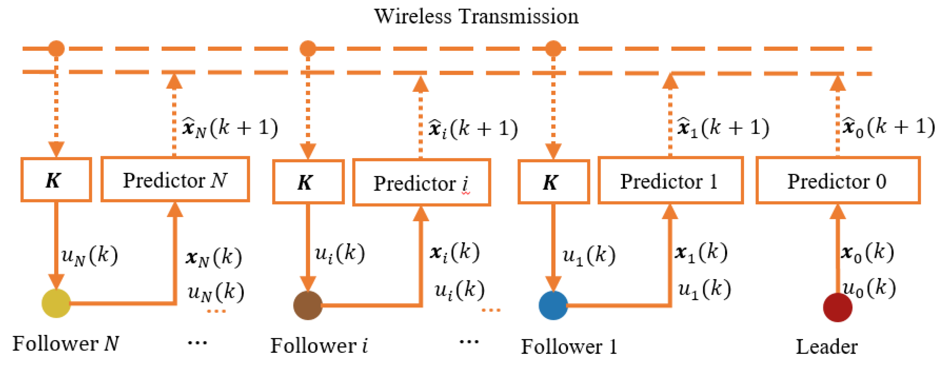
3.3. Closed-Loop Dynamical Function of Platoon

Considering the control objective, that is, all followers track leader with predefined constant space, the following state feedback control logic with the predicted state as feedback is used [23,26,31]:
u i ( k ) = K { j = 1 N l i j [ x i ( k ) x ^ j ( k ) d i j ] + p i [ x i ( k ) x ^ 0 ( k ) d i 0 ] } ,   i = 1 , , N ,
where d i j = [ ( i j ) d 0 0 ] T and d is the desired clearance between neighboring vehicles, K 3 is the distributed state feedback. Furthermore, the dynamical function of control error is obtained from (1):
e i ( k + 1 ) = A i e i ( k ) + B i u i ( k ) + A i x 0 ( k ) + B d ρ i ( k ) , i = 1 , , N ,
where e i ( k ) = x i ( k ) x 0 ( k ) d i 0 is the tracking control error, B d = [ A 0 B 0 ] and ρ i ( k ) = [ x 0 ( k ) u 0 ( k ) ] . The uncertain closed loop dynamics of platoon control system is formulated by substituting (2) and (5) to (6):
E ( k + 1 ) = ( I N A ) [ E ( k ) + X 0 ( k ) ] + ( I N H ) W ( k ) + [ G ( B K ) ] E ^ ( k ) + ( I N B d ) Γ ( k ) , W ( k ) = F Z ( k ) ,     Z ( k ) = ( I N H 1 ) [ E ( k ) + X 0 ( k ) ] + [ G ( H 2 K ) ] E ^ ( k ) ,
where E ( k ) = [ e 1 ( k ) e N ( k ) ] , Γ ( k ) = [ ρ 1 ( k ) ρ N ( k ) ] , E ^ ( k ) = [ x ^ 1 ( k ) x ^ 0 ( k ) d 10 x ^ N ( k ) x ^ 0 ( k ) d N 0 ] , X 0 ( k ) = 1 N x 0 ( k ) , the matrix H 1 ,   H 2 and H are used to normalize the platoon heterogeneity to a uniform uncertain format as the following:
A i = H F i H 1 ,       B i = H F i H 2 ,       i = 1 , , N , F = diag { F 1 , , F N } , F 1
where F i denotes the normalized heterogeneity of platoon.
Compared with the standard uncertain format used in robust control, (7) has the following differences: (a) An extra predicted tracking error E ^ ( k ) is in the closed loop; (b) The dimension, structure and entity of G all change with running because of the degradation of communication performance, cut in/off of adjacent vehicles and so forth. To overcome these problems, a topological decoupling strategy is proposed in Section 4.

4. Synthesis of Robust Control System for Platooning

Before presenting the decoupling synthesis approach, the following lemma about matrix decomposition is introduced:
Lemma 1
([23]). Any matrix P N × N has the following eigenvalue decomposition:
P = X Λ X 1 , X = X ˜ D ,
where Λ = diag ( Λ 1 , , Λ n ) N × N is composed of the eigenvalues λ i of P and   i = 1 n r a n k ( Λ i ) = N , X ˜ N × N is composed of the unit generalized eigenvectors of P , D N × N is a diagonal matrix to convert the unit eigenvector to general one and obviously X is also composed of the generalized eigenvectors of P . The diagonal block Λ i of Λ has four possibilities:
(a) Λ i = λ i if λ i and has only one linearly independent eigenvector;
(b) The Jordan format Λ i = [ λ i 1 1 λ i ] if λ i is a m -repeated eigenvalue and only has one linearly independent eigenvector;
(c) Λ i = [ α β β α ] if λ i = α + β j is a complex and has a pair of conjugate eigenvectors;
(d) Λ i = [ [ α β β α ] I 2 I 2 [ α β β α ] ] 2 m × 2 m if λ i = α + β j is a m -repeated eigenvalue and only has one pair of conjugate eigenvectors.

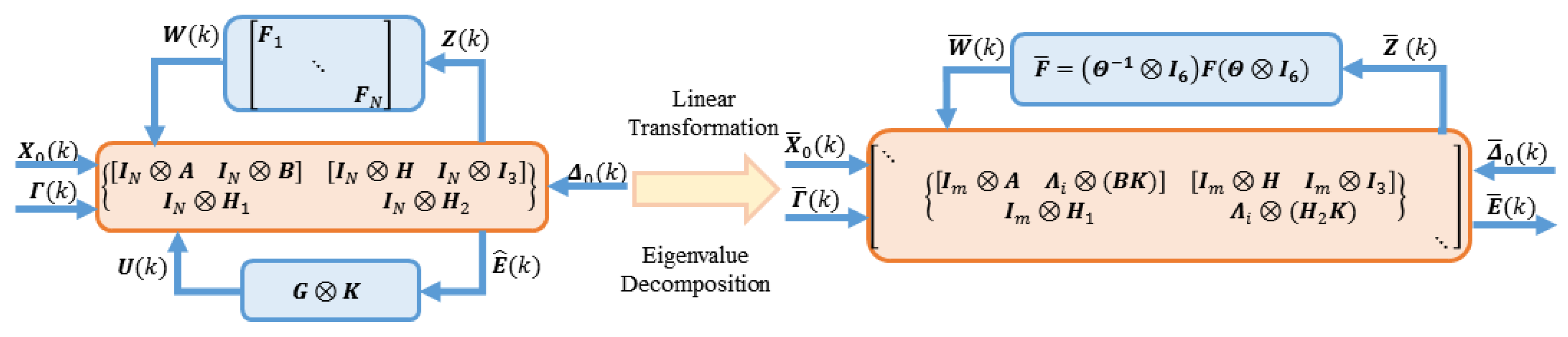
4.1. Topological Decoupling of Closed-Loop Platoon System

The fundamental of decoupling synthesis strategy is depicted in Figure 3.
According to Lemma 1, G has the following eigenvalue decomposition:
G = Θ Λ Θ 1 , Θ = Θ ˜ D ,
where Θ N × N is made up of the generalized eigenvectors of G , Λ = diag ( Λ 1 , , Λ n ) N × N and r a n k ( Λ i ) = m   . Substituting (10) to (7) and the decoupled format is obtained by linear transformation as shown in Figure 3:
E ¯ ( k + 1 ) = ( I N A ) [ E ¯ ( k ) + X ¯ 0 ( k ) ] + ( I N H ) W ¯ ( k ) + [ Λ ( B K ) ] [ E ¯ ( k ) Δ ¯ 0 ( k ) ] + Γ ¯ 0 ( k ) , Z ¯ ( k ) = ( I N H 1 ) E ¯ ( k ) + [ Λ ( H 2 K ) ] [ E ¯ ( k ) Δ ¯ 0 ( k ) ] ,
where E ¯ ( k ) = ( Θ 1 I 3 ) E ( k ) , W ¯ ( k ) = F ¯ Z ¯ ( k ) , X ¯ 0 = ( Θ 1 I 3 ) X 0 ( k ) , Γ ¯ 0 ( k ) = ( Θ 1 I 3 ) Γ 0 ( k ) , F ¯ = ( Θ 1 I 6 ) F ( Θ I 6 ) , Δ ¯ 0 ( k ) = ( Θ 1 I 3 ) Δ 0 ( k ) and Δ 0 ( k ) = 1 N u 0 ( k ) .
By this way, the coupling of G is partly transferred into F ¯ , whose uncertain degree is related to the design of robust controller directly. For an undirected graph, G is symmetrical and F ¯ = F [11,12]. Otherwise if G is asymmetric, F ¯ may be enlarged by the linear transformation, whose bound can be estimated by:
F ¯ σ ¯ ( Θ I 6 ) / σ _ ( Θ I 6 ) = σ ¯ ( Θ ) / σ _ ( Θ ) = ρ .
Such conversion can be reduced by optimizing D with such method as singular value analysis. Base on (11), the original platoon system with higher dimension and uncertain interaction is considered as multiple independent subsystems with lower order:
E ¯ i ( k + 1 ) = [ I m A + Λ i ( B K ) ] E ¯ i ( k ) + ( I m H ) W ¯ i ( k ) [ Λ i ( B K ) ] Δ ¯ 0 i ( k ) + [ I m B d ] Γ ¯ 0 i ( k ) , Z ¯ i ( k ) = ( I m H 1 ) E ¯ i ( k ) + [ Λ i ( H 2 K ) ] [ E ¯ i ( k ) Δ ¯ 0 i ( k ) ] ,       i = 1 , , n .
where E ¯ i ( k ) , W ¯ i ( k ) , Δ ¯ 0 i ( k ) , Γ ¯ 0 i ( k ) , Z ¯ i ( k ) are the corresponding parts in (11). The following theorem establishes the performance relationship between the platoon system before and after decoupling, which is the basis to numerically solve the state feedback using the decoupled format.
Theorem 1.
For the platoon described by (7), if there exist positive constants α 1 , β 1 , α 2 , β 2 such that all decoupled subsystems in (13) satisfy
Z ¯ i 2 2 α 1 W ¯ i 2 2 + β 1 ( Γ ¯ 0 i 2 2 + Δ ¯ 0 i 2 2 ) , ( I m Q ) E ¯ i 2 2 α 2 W ¯ i 2 2 + β 2 ( Γ ¯ 0 i 2 2 + Δ ¯ 0 i 2 2 ) , i = 1 , , n .
then the original system has robust performance with the weighting matrix Q :
( I N Q ) E 2 μ Γ ˜ 2 ,
where Γ ˜ = [ Γ Δ 0 ] and μ = ρ β 2 + α 2 β 1 ρ 2 1 α 1 ρ 2 .
Proof. 
From (11) and the second inequality in (14), we have
( I N Q ) E 2 2 σ ¯ 2 ( Θ ) [ α 2 W ¯ 2 2 + β 2 ( Γ ¯ 2 2 + Δ ¯ 0 2 2 ) ] , Z ¯ 2 2 α 1 W ¯ i 2 2 + β 1 ( Γ ¯ 2 2 + Δ ¯ 0 2 2 ) ,             W ¯ 2 2 F ¯ 2 · Z ¯ 2 2 ρ 2 Z ¯ 2 2 .
Substituting F ¯ ρ to (16) yields (17), which is equivalent to (15) and the conclusion is proved.
( I N Q ) E 2 ρ β 2 + α 2 β 1 ρ 2 1 α 1 ρ 2 Γ ˜ 2 .
Theorem 1 converts the performance requirements of platoon system into that of its decoupled format, whose dimension is much smaller and the unknown interactions can be evaluated by certain information, that is, eigenvalues and decomposition formats of G .

4.2. Numerical Design of State Feedback Controller

The following theorem provides a numerical way to solve the required distributed state feedback using LMI, which ensures robust stability, tracking performance and disturbance attenuation ability.
Theorem 2.
If there exist matrices Σ = Σ T > 0 3 × 3 , W 1 × 3 and constants α 1 , α 2 ,     β 1 ,     β 2 > 0 , such that the following LMIs establish:
[ S 11 S 12 S 22 ] < 0 , [ S 33 S 34 S 44 ] < 0   ,     S 11 = [ I m Σ 0 I 6 m ] , S 12 = [ I m ( A Σ ) + Λ i ( B W ) I m H I m B d Λ i ( B W ) I m ( H 1 Σ ) + Λ i ( H 2 W ) 0 0 Λ i ( H 2 W ) ] S 22 = diag ( I m Σ , α 1 I 6 m , β 1 I 12 m , β 1 I m Σ 2   ) ,   S 44 = [ α 2 I 6 m 0 0 β 2 I 12 m 0 β 2 I m Σ 2 ] ,   S 33 = [ I m Σ I m ( A Σ ) + Λ i ( B W ) I m ( Σ Q T Q Σ Σ ) ] , S 34 = [ I m H I m B d Λ i ( B W ) 0 0 0 ] ,     i = 1 , , n ,
then with the distributed state feedback K = W Σ 1 , the platoon is asymptotic stable and with the weighting matrix Q ϵ 3 × 3 , the disturbance   Γ ˜ ( k ) is attenuated by
( I N Q ) E 2 μ Γ ˜ 2 .
Proof. 
Left and right multiplying the left side of the first inequality in (18) with diag { I 3 m , I 6 m , I m Σ 1 , I 6 m , I 12 m , I m Σ 1 } and substituting K = W Σ 1 to it, we get:
[ S 11 S ¯ 12 S ¯ 22 ] < 0 ,   S ¯ 12 = [ I m A + Λ i ( B K ) I m H I m B d Λ i ( B K ) I m H 1 + Λ i ( H 2 K ) 0 0 Λ i ( H 2 K ) ] , S ¯ 22 = diag ( I m Σ 1 , α 1 I 6 m , β 1 I 12 m , β 1 β 1 I 3 m   ) .
Applying the Schur Supplement Theorem on (20) yields [32]:
S ¯ 22 S ¯ 12 T S 11 1 S ¯ 12 < 0 .
From (21), the following inequality establishes:
[ I m A + Λ i ( B K ) ] T ( I m Σ 1 ) [ I m A + Λ i ( B K ) ] < I m Σ 1 < 0 .
Therefore (13) is asymptotic stable according to the Lyapunov stability theory and the corresponding Lyapunov function is V i ( k ) = E ¯ i T ( k ) ( I m Σ 1 ) E ¯ i ( k ) . And so the platoon system is also asymptotic stable because linear transformation will not change the stability of linear system.
Furthermore defining new Lyapunov function V i ( k ) = e ¯ i T ( k ) Σ 1 e ¯ i ( k ) , Δ V i ( k ) = V i ( k + 1 ) V i ( k ) and
L 1 i ( k ) = Z ¯ i ( k ) 2 2 α 1 W ¯ i ( k ) 2 2 β 1 ( Γ ¯ 0 i 2 2 + Δ ¯ 0 i 2 2 ) , L 2 i ( k ) = ( I m Q ) E ¯ i 2 2 α 2 W ¯ i ( k ) 2 2 β 2 ( Γ ¯ 0 i 2 2 + Δ ¯ 0 i 2 2 ) , i = 1 , , n .
The first equation in (23) is re-written by substituting (13) to it:
L 1 i ( k ) = [ E ¯ i ( k ) W ¯ i ( k ) Γ ¯ 0 i ( k ) Δ ¯ 0 i ( k ) ] T ( S ¯ 22 S ¯ 12 T S 11 1 S ¯ 12 ) [ E ¯ i ( k ) W ¯ i ( k ) Γ ¯ 0 i ( k ) Δ ¯ 0 i ( k ) ] Δ V i ( k ) ,   i = 1 , , n .
Then we have L 1 i ( k ) < Δ V i ( k ) , that is,
Z ¯ i ( k ) 2 2 < α 1 W ¯ i ( k ) 2 2 β 1 ( Γ ¯ 0 i 2 2 + Δ ¯ 0 i 2 2 ) Δ V i ( k ) ,       i = 1 , , n .
The initial state is assumed to be zero and V i ( 0 ) = 0 and the following inequality is derived by summarizing all sampling time from k = 0 , , N ¯ together:
k = 0 N ¯ Z ¯ i ( k ) 2 2 < k = 0 N ¯ [ α 1 W ¯ i ( k ) 2 2 β 1 ( Γ ¯ 0 i 2 2 + Δ ¯ 0 i 2 2 ) ] V i ( N ¯ + 1 ) .
Since the platoon is asymptotic stable, lim N   V i ( N ) = 0 and substituting it to (26) yields
Z ¯ i 2 2 α 1 W ¯ i 2 2 + β 1 ( Γ ¯ 0 i 2 2 + Δ ¯ 0 i 2 2 ) , i = 1 , , n .
Similar to the analysis of (20)–(27), the following inequality also establishes:
( I m Q ) E ¯ i 2 2 α 2 W ¯ i 2 2 + β 2 ( Γ ¯ 0 i 2 2 + Δ ¯ 0 i 2 2 ) , i = 1 , , n .
Equation (19) is obtained from Theorem 1 by combining (27) and (28) and Theorem 2 is proved.

5. Closed Loop Performance Analysis

5.1. Internal Stability

This section focuses on the analysis of delay on closed loop stability. To simplify the theoretical analysis, it is assumed that the time constant of vehicle drive dynamics is the same, that is, τ i = τ , i = 0 , 1 , , N and there is no Jordan format in the eigenvalue decomposition of G . Then the dynamics of vehicle node becomes [11,23]:
x 0 ( k + 1 ) = A ¯ x i ( k ) + B ¯ u i ( k ) , i = 0 , 1 , , N .
where A ¯ = [ 1 h τ 2 ϖ + τ h 0 1 τ ϖ 0 0 ϖ + 1 ] , B ¯ = [ τ 2 ϖ τ h + 1 2 h 2 τ ϖ + h ϖ ] , ϖ = e h τ 1 and h is the sample period.
Note that there are two types of stability for platoon, that is, internal stability [17] and string stability [5]. The following analysis focuses on the influence of delay on internal stability of platoon controlled by the distributed state feedback which is pre-designed in Section 4.2. The internal stability is defined as following.
Internal stability. A linear and time-invariant platoon is said to be asymptotic stable, if and only if all the eigenvalues of its discrete closed-loop system are located in the union disk of complex plane, that is, the magnitude of all eigenvalues is less than 1.
It is known from the previous studies that the internal stability criterion is not compact enough to get the parameter range directly, because Jury Criterion uses roots of equations [33]. The following Lemma gives a sufficient and necessary condition of internal stability, which is the basis to study the influence of delay and topology on platoon internal stability.
Lemma 2
([33]). Given a characteristic polynomial of third-order discrete system:
D ( z ) = z 3 + c 2 z 2 + c 1 z + c 0 ,
where c 0 , c 1 and c 2 are coefficients and the system is stable if and only if the following inequalities establish:
{       D ( 1 ) > 0 , D ( 1 ) > 0 ,                 1 > | c 0 | ,                     1 c 0 2 > | c 1 c 2 c 0 | .
Similar to the analysis process of heterogeneous platoon, the characteristic polynomial of studied homogeneous platoon system in this section is obtained by combing (29) with pre-designed state feedback K = [ k p k v k a ] in Section 4.2:
D ( z ) = | z I ( G + λ ϕ K ) | = z 3 + c 2 z 2 + c 1 z + c 0 ,
where c 0 = y T A ¯ 0 y + B ¯ 0 y 1 , c 1 = y T A ¯ 1 y + B ¯ 1 y + 3 and c 2 y T A ¯ 2 y + B ¯ 2 y 3 are the coefficients whose variables are calculated by
A ¯ 0 = [ k p λ 2 λ ( k p τ + k v ) 2 k p λ 4 2 τ λ ( k v k p τ ) k p τ λ 0 ] , A ¯ 1 = [ 0 λ ( k p τ + k v ) 2 k p λ 4 2 τ λ ( k v k p τ ) 0 0 ] , A ¯ 2 = [ k p λ 2 0 0 0 0 0 ] , B ¯ 0 = [ ( k p τ k v ) λ ( k p τ + k v ) τ λ + k a λ 1 ( k p λ + k v ) τ ] , B ¯ 1 = [ 2 ( k v k p τ ) λ 2 ( k p τ k v ) τ λ 2 k a λ + 2 ( k p τ + k v ) λ ] ,       y = [ h ϖ h ϖ ] T , B ¯ 2 = [ ( k a τ k v ) λ ( k p τ + k v ) τ λ + k a λ 1 0 ] .
The sufficient and necessary condition ensuring internal stability is derived from Lemma 2 as:
{ f 1 ( y ) = y T ( A ¯ 0 + A ¯ 1 + A ¯ 2 ) y + ( B ¯ 0 + B ¯ 1 + B ¯ 2 )   y > 0 f 2 ( y ) = y T ( A ¯ 0 + A ¯ 1 + A ¯ 2 ) y + ( B ¯ 0 + B ¯ 1 + B ¯ 2 ) y + 8 > 0 f 3 ( y ) = 1 | y T A ¯ 0 y + B ¯ 0 y 1 | > 0 f 4 ( y ) = 1 c 0 2 | c 1 c 2 c 0 | > 0 .

5.2. Numerical Analysis

In this section the influence of topology and delay on platoon internal stability is studied numerically based on the sufficient and necessary condition (34), from which the platoon internal stability can be measured by index f m i n = min i = 1 , , 4 f i ( y ) . Moreover, considering the fact that linear transformation does not change the system stability and the decoupling synthesis strategy in Section 4.1, the influence of topology is expressed by its eigenvalues. During the numerical analysis, τ = 0.5 , h = 0.1 and the state feedback is K = [ 5.75 5.05 1.03 ] designed by Theorem 1. The numerical analysis results are shown in Figure 4.
From (34), it is known that the platoon is internal stable if and only if f m i n > 0 . Then from Figure 4a, it is found that with the increasing of both of delay and eigenvalue, the platoon tends to be instable. The former phenomenon is consistent with the common sense while the latter is different from the previous conclusions without considering delay in Reference [23]. The previous studies show that both of the stability region and scalability of platoon is limited by the minimum eigenvalue of G . When considering the time delay, the internal stability is also affected by the maximum eigenvalue as shown in Figure 4b and the allowable delay decreases with the increase of it. From the decoupled format of platoon in (13), the topological eigenvalue equivalently acts on the open loop gain of control system. And from the stability theory of delay system, it is known that a higher gain is bad for the stability. According to our discovery and the communication delay is unavoidable in practical, the maximum topological eigenvalue also need to be considered when synthesizing a platoon control system.

6. Simulation and Discussion

To validate the effectiveness and further analysis of the proposed decoupling synthesis strategy, numerical simulations are conducted in this section. The simulated heterogeneous platoon includes 1 leader and 5 followers. During simulation, v 0 ( 0 ) = = v N ( 0 ) = 5   m / s , d = 10   m , K = [ 5.75 5.05 1.03 ] , h = 0.1   s except where noted, the platoon heterogeneity is reflected by τ i pre-selected in [ 0.3   s ,   0.7   s ] randomly. A statistical model is used to describe the communication delay, which is a function of the distance two communicated nodes [26]. The acceleration and velocity profiles of leader are shown in Figure 5, which are from the naturalistic driving data.

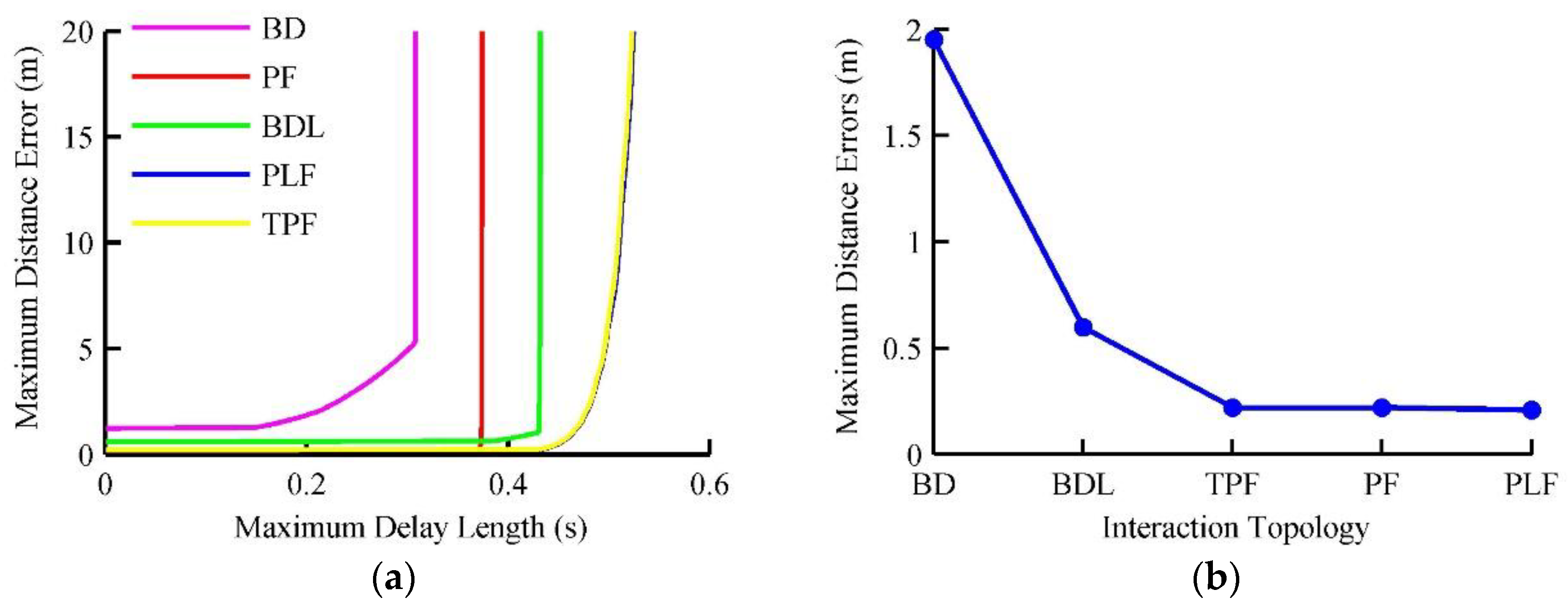
6.1. Delay Bound under Different Topologies

Note that the condition in Theorem 1 is sufficient but not necessary, which implies that the designed controller still may be applicable even if LMIs in (18) are infeasible. And so in this section, we further study the actual maximum delay under different topologies. During this simulation, the maximum allowable delay is increased gradually and the maximum distance tracking error under different topologies is shown in Figure 6.
As shown in Figure 6a, the maximum distance tracking error, that is, the maximum one of all followers, monotonically increases with the delay. The maximum error of BD is smaller than 2m when the delay is smaller than 0.15 s. Then it increases slowly to 5 m with the delay increases to 0.3s, after which increases sharply and even collision occurs. The maximum distance errors of other topologies agree with the trend of BD. When designing the controller, the sample period is set to 0.1s, which is large enough compared with the end-to-end communication delay of IEEE 802.11p (about 0.01s) [30]. It is found from Figure 6a that the control performance is still stable even the delay exceeds 0.1s. This shows that LMIs in (18) only are sufficient conditions and the solved controller still can control platoon acceptably even the system runs out of the designed constraints.
To show the influence of topology on distance tracking performance more clearly, the tracking error profile under the condition that the maximum delay is 0.1s is extracted shown in Figure 6b. The maximum errors of BD, BDL, TPF, PF and PLF are 1.95 m, 0.6 m, 0.22 m, 0.22 m, 0.21 m respectively. And maximum eigenvalues of these normalized topologies are 1.9511, 1.6236, 1, 1, 1 accordingly. It agrees with the results of numerical analysis in Section 5.2 that the performance is also affected by the maximum topological eigenvalue.

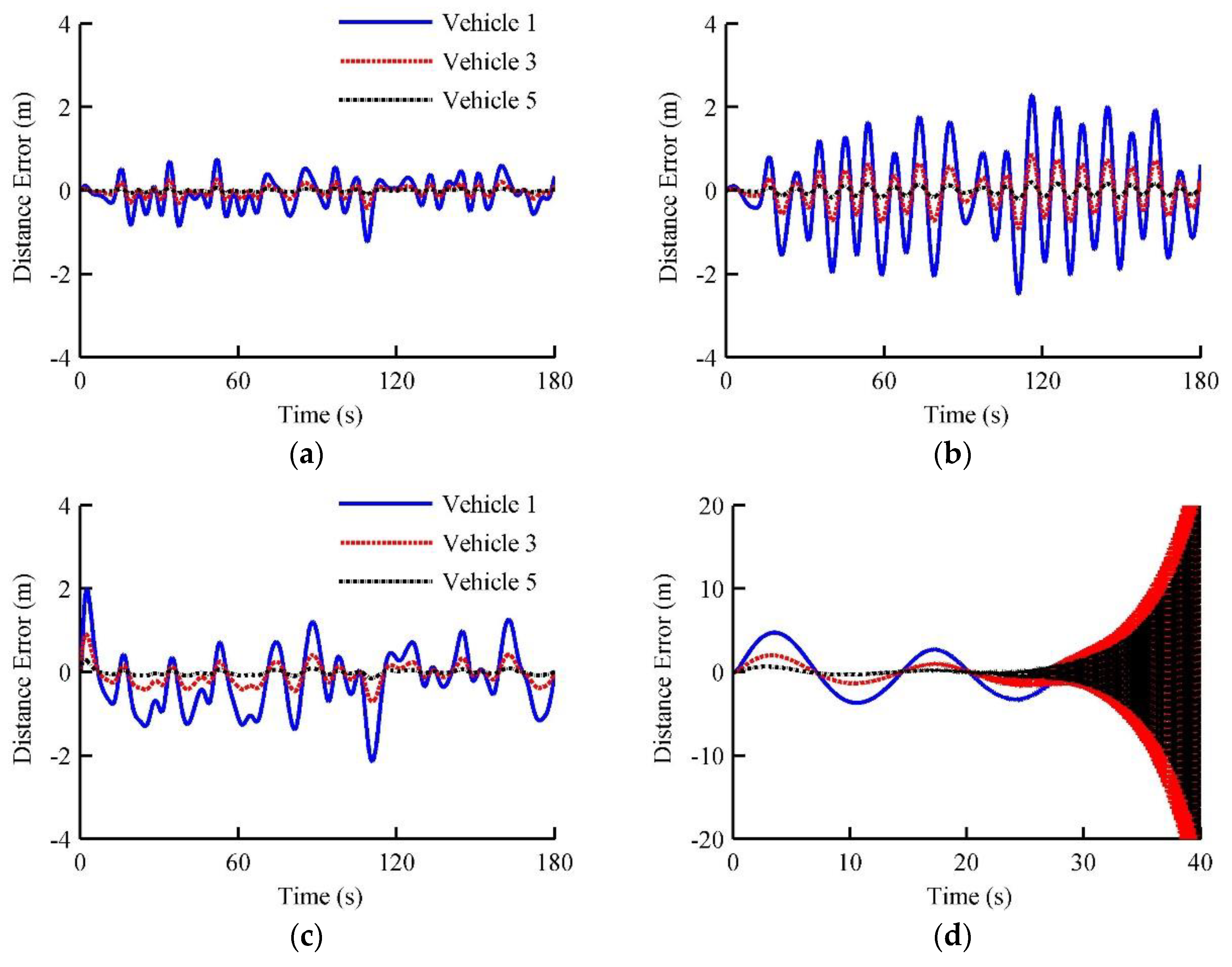
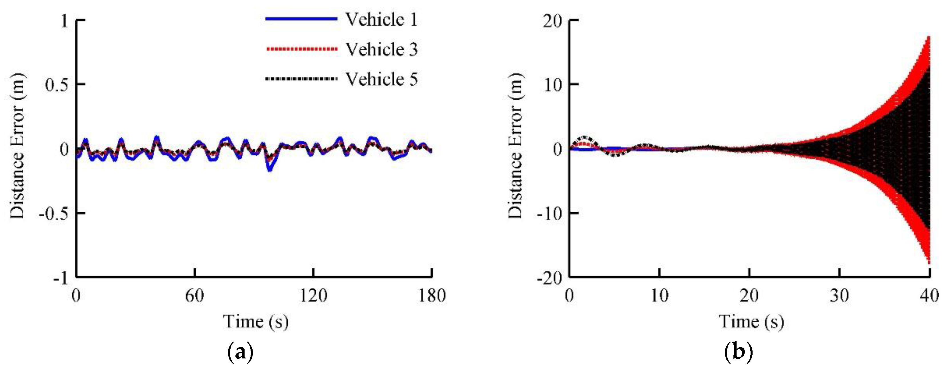
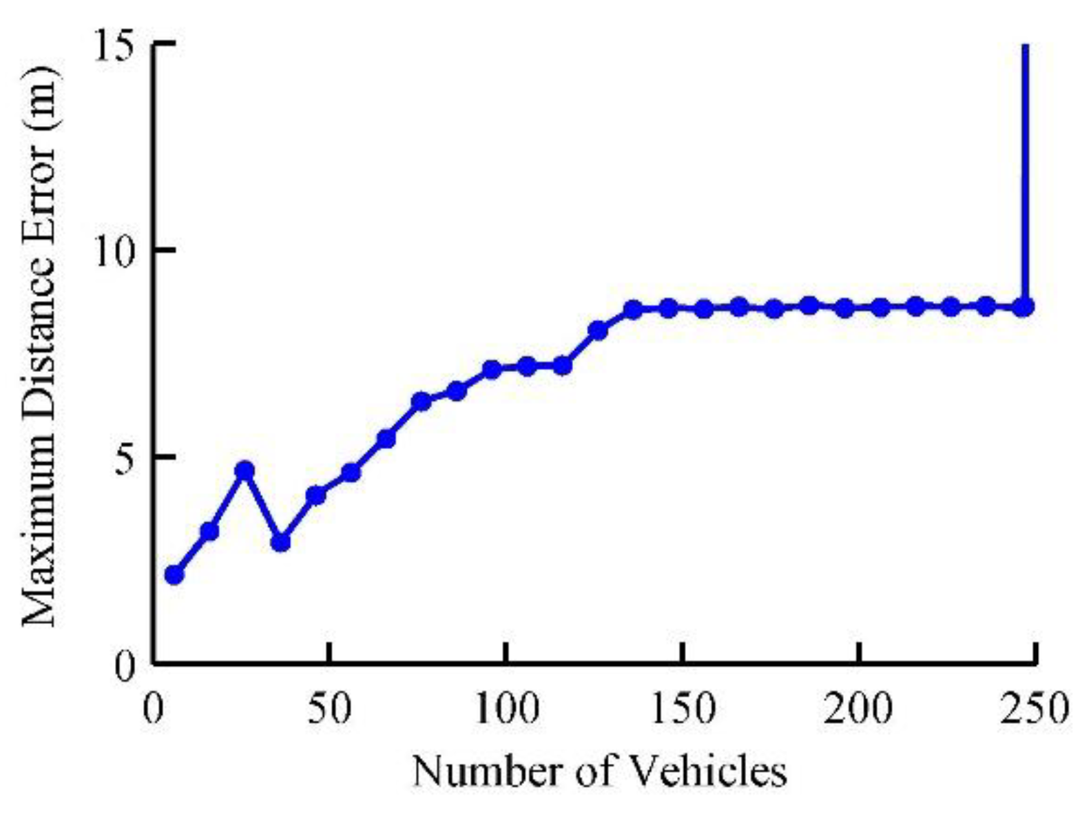
6.2. Comparison of Stability Performance

To show the necessity of considering information delay, a comparison simulation between the proposed method (denoted by method 1) and an existing one (denoted by method 2) without considering delay [11] is conducted in this section. During simulation, the topology is BD having the worst performance in Section 6.1 and the maximum delay is set to 0.001s and 0.08s respectively. The former delay is negligible compared with the control period and the latter is a typical value of general V2V [30]. The compared simulation results are shown in Figure 7.
It can be found from Figure 7a,b that the maximum distance errors of method 1 and 2 are 1.1   m and 2.5   m respectively, which both are less than the desired spacing and a stable dynamics of platoon is guaranteed when the delay is negligible. If the delay increases to 0.08s, the maximum error of method 1 is 2.2m the platoon runs stably, while the platoon controlled by method 2 becomes unstable as shown in Figure 7c,d. Moreover, the compared control results of platoon interacted by the optimal one in Section 6.1, that is, PF is shown in Figure 8. The maximum delay is set to 0.1   s and method 1 achieves a much better one than BD while method 2 still cannot ensure the platoon stability.
Note that the eigenvalue varies with platoon length for some topologies such as BD. Figure 9 shows this further results of the influence of platoon length on control performance with the maximum information delay 0.08s and BD topology. As shown in Figure 9, the maximum error increases with the platoon length gradually when the vehicle number is smaller than about 140, after which the maximum error reaches about 9m and keeps almost unchanged. After the vehicle number reaches 248, the platoon become unstable. The reason is that both the minimum and maximum eigenvalues change with the dimension of BD, which affect the closed loop dynamics of platoon.

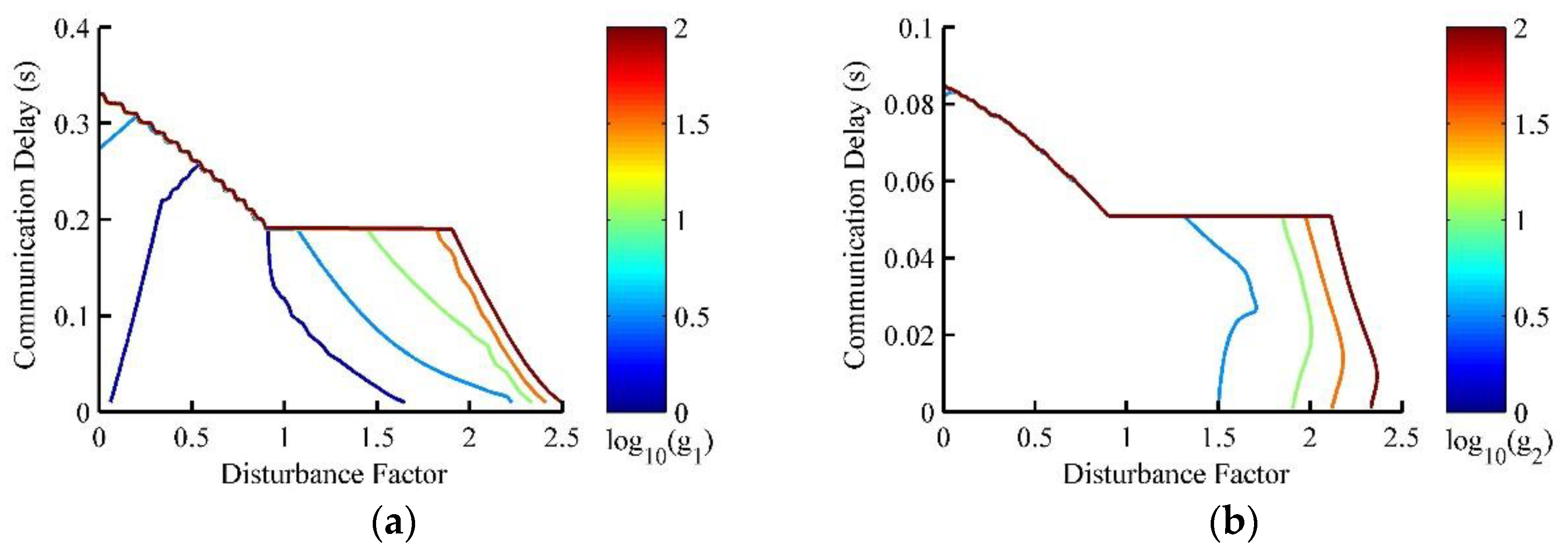
6.3. Robustness Performance Analysis

The robust performance considering both delay and parametric uncertainty is studied by comparative simulations in this section to further validate the effectiveness of the proposed method. During the simulation, the platoon is interacted by BD, the platoon heterogeneity evaluated by τ i (0 means a homogeneous platoon) and the maximum delay are increased gradually and the robust performance is measured by the maximum distance tracking error among all followers. The comparative results of robust performance are shown in Figure 10, where g 1 and g 2 represent the maximum distance errors of method 1 and method 2 respectively. When there is no information delay, the allowable disturbances of method 1 and method 2 are 2.3 and 1.8 respectively, which implies that two methods have the similar robust performance and both can attenuate the platoon heterogeneity efficiently. Furthermore, the robust performances of platoon controlled by both two methods are deteriorated with the increase of information delay but the stability region of method 1 is much wider than that of method 2 (denoted by green line). Under the condition that the maximum delay reaches 0.08 s, the allowable disturbance of method 1 is 2.2 but that of method 2 is only 0.2. This shows that method 1 has much better robustness than method 2.

7. Conclusions

This paper presents a state predictor based control strategy for heterogeneous vehicular platoon connected by non-ideal wireless communication. From the theoretical analysis and simulation results, we have the following conclusions:
  • Both information delay and topological uncertainty caused by non-ideal wireless communication are critical to the stability and tracking performances of platoon, which need to be dealt with when synthesizing a platoon control system;
  • When considering the information delay, besides the minimum topological eigenvalue the maximum one also affects the closed loop performance of platoon. And comparatively, the influence of minimum one can be ignored if only stability is taken into account.
  • The proposed state predictor based control strategy can compensate for the information delay and the numerical approach based on LMI can find the required state feedback controller ensuring robust performance of platoon.

Author Contributions

B.L. and F.G. took the theoretical analysis and wrote the paper; Y.H. and C.W. performed the numerical simulation and data analysis.

Acknowledgments

This work was supported by National key research and development program under grant 2016YFB0100900 and 2016YFB0101104, Open Fund of State Key Laboratory of Vehicle NVH and Safety (NVHSKL-201705), Industrial Base Enhancement Project (2016ZXFB06002).

Conflicts of Interest

The authors declare no conflict of interest.

References

  1. Banister, D.; Anderton, K.; Bonilla, D.; Givoni, M.; Schwanen, T. Transportation and the Environment. Soc. Sci. Elect. Pub. 2011, 36, 9–12. [Google Scholar] [CrossRef]
  2. Li, S.; Li, R.; Wang, J.; Hu, X.; Cheng, B.; Li, K. Stabilizing Periodic Control of Automated Vehicle Platoon with Minimized Fuel Consumption. IEEE Trans. Transp. Electr. 2017, 3, 259–271. [Google Scholar] [CrossRef]
  3. Swaroop, D.; Hedrick, J.K.; Choi, S.B. Direct adaptive longitudinal control of vehicle platoons. IEEE Trans. Veh. Technol. 2001, 50, 150–161. [Google Scholar] [CrossRef]
  4. Kunze, R.; Ramakers, R.; Henning, K.; Jeschke, S. Organization and Operation of Electronically Coupled Truck Platoons on German Motorways. In Proceedings of the International Conference on Intelligent Robotics and Applications (ICIRA 2009), Singapore, 16–18 December 2009; pp. 135–146. [Google Scholar]
  5. Shladover, S.E.; Desoer, C.A.; Hedrick, J.K.; Tomizuka, M.; Walrand, J.; Zhang, W.B.; Mckeown, N. Automated vehicle control developments in the PATH program. IEEE Trans. Veh. Technol. 2002, 40, 114–130. [Google Scholar] [CrossRef]
  6. Tsugawa, S.; Kato, S.; Aoki, K. An automated truck platoon for energy saving. In Proceedings of the IEEE/RSJ International Conference on Intelligent Robots and Systems, San Francisco, CA, USA, 25–30 September 2011; pp. 4109–4114. [Google Scholar]
  7. Kim, D.J.; Park, K.H.; Bien, Z. Hierarchical Longitudinal Controller for Rear-End Collision Avoidance. IEEE Trans. Ind. Elect. 2007, 54, 805–817. [Google Scholar] [CrossRef]
  8. Li, S.B.; Gao, F.; Cao, D.; Li, K. Multiple-model switching control of vehicle longitudinal dynamics for platoon level automation. IEEE Trans. Veh. Technol. 2016, 65, 4480–4492. [Google Scholar] [CrossRef]
  9. Caravani, P.; Santis, E.D.; Graziosi, F.; Panizzi, E. Communication Control and Driving Assistance to a Platoon of Vehicles in Heavy Traffic and Scarce Visibility. IEEE Trans. Intell. Transp. 2006, 7, 448–460. [Google Scholar] [CrossRef]
  10. Liu, B.; Jia, D.; Lu, K.; Dong, N.; Wang, J.; Wu, L. A Joint Control-Communication Design for Reliable Vehicle Platooning in Hybrid Traffic. IEEE Trans. Veh. Technol. 2017, 66, 9394–9409. [Google Scholar] [CrossRef]
  11. Zheng, Y.; Li, S.E.; Li, K.; Wang, L.Y. Stability Margin Improvement of Vehicular Platoon Considering Undirected Topology and Asymmetric Control. IEEE Trans. Control Syst. Technol. 2016, 24, 1253–1265. [Google Scholar] [CrossRef]
  12. Xia, Q.; Gao, F.; Duan, J.; He, Y. Decoupled H-inf Control of Automated Vehicular Platoons with Complex Interaction Topologies. IET Intell. Transp. Syst. 2017, 11, 92–101. [Google Scholar] [CrossRef]
  13. Rödönyi, G. An Adaptive Spacing Policy Guaranteeing String Stability in Multi-Brand Ad Hoc Platoons. IEEE Trans. Intell. Transp. 2017, 19, 1902–1912. [Google Scholar] [CrossRef]
  14. Sakoda, K. Wireless communication apparatus, communication system, wireless communication apparatus control method and program. Commun. Mag. 2017, 97, 1–9. [Google Scholar]
  15. Yang, N.; Wang, L.; Geraci, G.; Elkashlan, M. Safeguarding 5G wireless communication networks using physical layer security. Commun. Magaz. 2015, 53, 20–27. [Google Scholar] [CrossRef]
  16. Liu, X.; Goldsmith, A.; Mahal, S.S.; Hedrick, J.K. Effects of communication delay on string stability in vehicle platoons. In Proceedings of the Intelligent Transportation Systems, Oakland, CA, USA, 25–29 August 2001; pp. 625–630. [Google Scholar]
  17. Ghasemi, A.; Kazemi, R.; Azadi, S. Stable Decentralized Control of a Platoon of Vehicles with Heterogeneous Information Feedback. IEEE Trans. Veh. Technol. 2013, 62, 4299–4308. [Google Scholar] [CrossRef]
  18. Alam, A.; Gattami, A.; Johansson, K.H.; Tomlin, C.J. Guaranteeing safety for heavy duty vehicle platooning: Safe set computations and experimental evaluations. Control Eng. Pract. 2014, 24, 33–41. [Google Scholar] [CrossRef]
  19. Gao, F.; Hu, X.; Li, S.B.; Li, K.; Sun, Q. Distributed adaptive sliding mode control of vehicular platoon with uncertain interaction topology. IEEE Trans. Ind. Electron. 2018, 65, 6352–6361. [Google Scholar] [CrossRef]
  20. Dunbar, W.B.; Caveney, D.S. Distributed Receding Horizon Control of Vehicle Platoons: Stability and String Stability. IEEE Trans. Autom. Control 2012, 57, 620–633. [Google Scholar] [CrossRef]
  21. Lestas, I.; Vinnicombe, G. Scalable Robustness for Consensus Protocols with Heterogeneous Dynamics. IFAC Proc. Vol. 2005, 38, 185–190. [Google Scholar] [CrossRef]
  22. Young, G.F.; Scardovi, L.; Leonard, N.E. Robustness of noisy consensus dynamics with directed communication. In Proceedings of the American Control Conference, Baltimore, MD, USA, 30 June–2 July 2010; pp. 6312–6317. [Google Scholar]
  23. Zheng, Y.; Li, S.E.; Wang, J.; Cao, D.; Li, K. Stability and Scalability of Homogeneous Vehicular Platoon: Study on the Influence of Information Flow Topologies. IEEE Trans. Intell. Transp. 2015, 17, 14–26. [Google Scholar] [CrossRef]
  24. Peters, A.A.; Middleton, R.H.; Mason, O. Leader tracking in homogeneous vehicle platoons with broadcast delays. Automatica 2014, 50, 64–74. [Google Scholar] [CrossRef]
  25. Gong, J.; Zhao, Y.; Lu, Z. Sampled-data vehicular platoon control with communication delay. Syst. Control Eng. 2017, 232, 39–49. [Google Scholar] [CrossRef]
  26. Gao, F.; Li, S.E.; Zheng, Y.; Kum, D. Robust control of heterogeneous vehicular platoon with uncertain dynamics and communication delay. IET Intel. Transp. Syst. 2016, 10, 503–513. [Google Scholar] [CrossRef]
  27. Bernardo, M.D.; Salvi, A.; Santini, S. Distributed Consensus Strategy for Platooning of Vehicles in the Presence of Time-Varying Heterogeneous Communication Delays. IEEE Trans. Intell. Transp. 2015, 16, 102–112. [Google Scholar] [CrossRef]
  28. Narasimha, M.; Desai, V.; Calcev, G.; Xiao, W.; Sartori, P.; Soong, A. Performance Analysis of Vehicle Platooning Using a Cellular Network. In Proceedings of the Vehicular Technology Conference, Toronto, ON, Canada, 24–27 September 2017. [Google Scholar]
  29. Campolo, C.; Molinaro, A.; Araniti, G.; Berthet, A. Better Platooning Control Toward Autonomous Driving: An LTE Device-to-Device Communications Strategy That Meets Ultralow Latency Requirements. IEEE Veh. Technol. Mag. 2017, 12, 30–38. [Google Scholar] [CrossRef]
  30. Masini, B.; Bazzi, A.; Zanella, A. A Survey on the Roadmap to Mandate on Board Connectivity and Enable V2V-Based Vehicular Sensor Networks. Sensors 2018, 18. [Google Scholar] [CrossRef] [PubMed]
  31. Li, K.; Gao, F.; Li, S.B.; Zheng, Y.; Gao, H. Robust cooperation of connected vehicle systems with eigenvalue-bounded interaction topologies in the presence of uncertain dynamics. Front. Mech. Eng. 2018, 13, 354–367. [Google Scholar] [CrossRef]
  32. Gao, F.; Li, S.E.; Kum, D.; Zhang, H. Synthesis of multiple model switching controllers using H theory for systems with large uncertainties. Neurocomputing 2015, 157, 118–124. [Google Scholar] [CrossRef]
  33. Jury, E.I. A Simplified Stability Criterion for Linear Discrete Systems. Proc. IRE 1962, 50, 1493–1500. [Google Scholar] [CrossRef]
Figure 1. Problems arising from V2V. (a) Varieties of information flow topologies. (b) Fundamental of state predictor.
Electronics 08 00207 g001
Figure 2. State predictor based platoon control system.
Electronics 08 00207 g002
Figure 3. Fundamental of platoon decoupling.
Electronics 08 00207 g003
Figure 4. Influence of delay and topology on internal stability. (a) Results of f m i n . (b) Allowable communication delay.
Electronics 08 00207 g004
Figure 5. Profiles of leader state. (a) Leader Acceleration. (b) Leader velocity.
Electronics 08 00207 g005
Figure 6. The upper limit of communication delay under different topologies. (a) Maximum delay of different topologies. (b) Maximum distance errors under different topologies.
Electronics 08 00207 g006
Figure 7. Compared results of different control methods. (a) Method 1 (Maximum delay is 0.001   s ). (b) Method 2 (Maximum delay is 0.001   s ). (c) Method 1 (Maximum delay is 0.08   s ). (d) Method 2 (Maximum delay is 0.08   s ).
Electronics 08 00207 g007
Figure 8. Stability performance of platoon interacted by PF. (a) Method 1 (Maximum delay is 0.1   s ). (b) Method 2 (Maximum delay is 0.1   s ).
Electronics 08 00207 g008
Figure 9. Influence analysis of platoon length.
Electronics 08 00207 g009
Figure 10. Robustness performance of platoon interacted by BD. (a) Maximum distance error of method 1. (b) Maximum distance error of method 2.
Electronics 08 00207 g010

