Abstract
This paper proposes the use of a control algorithm that can yield soft switching both at turn-on and turn-off of the inverter of series resonance converter (SRC) gas metal arc welding (GMAW) machines. The technique takes advantage of the band-pass filter characteristics of the SRC and controls the power by using switching frequencies that are subharmonics of the resonance frequency. The design and the experimental results for a 5 kW prototype system are given to prove that the algorithm can be used in GMAW systems.
1. Introduction
Flexibility, high speed, and capability of employing different types and thicknesses of materials make gas metal arc welding (GMAW) one of the most widely used processes in industrial and manufacturing operations. Commercial arc welders can be made in smaller sizes with the same capability by reducing the volume of the passive components such as transformers and filter inductors, and cooling parts such as heatsinks [1,2,3]. This can be achieved by increasing the switching frequency and utilizing soft switching techniques to decrease the losses. The power level in traditional welders is usually up to several kilowatts and they are more likely to use Insulated Gate Bipolar Transistor (IGBT) devices. The high current IGBTs usually can be switched at about 20 kHz [4] with a hard switching method. Resonant converters such as the LLC and the series resonant converter (SRC) achieve soft switching-like lossless switching transitions, pushing the switching frequency and efficiency to higher values and reducing the electromagnetic interference (EMI). They also have a wide operating frequency range and thus do not need filter inductors so that the volume and weight are comparatively reduced. On the other hand, resonant converters produce higher RMS current values than their square waveform counterparts, causing increased conduction losses [5].
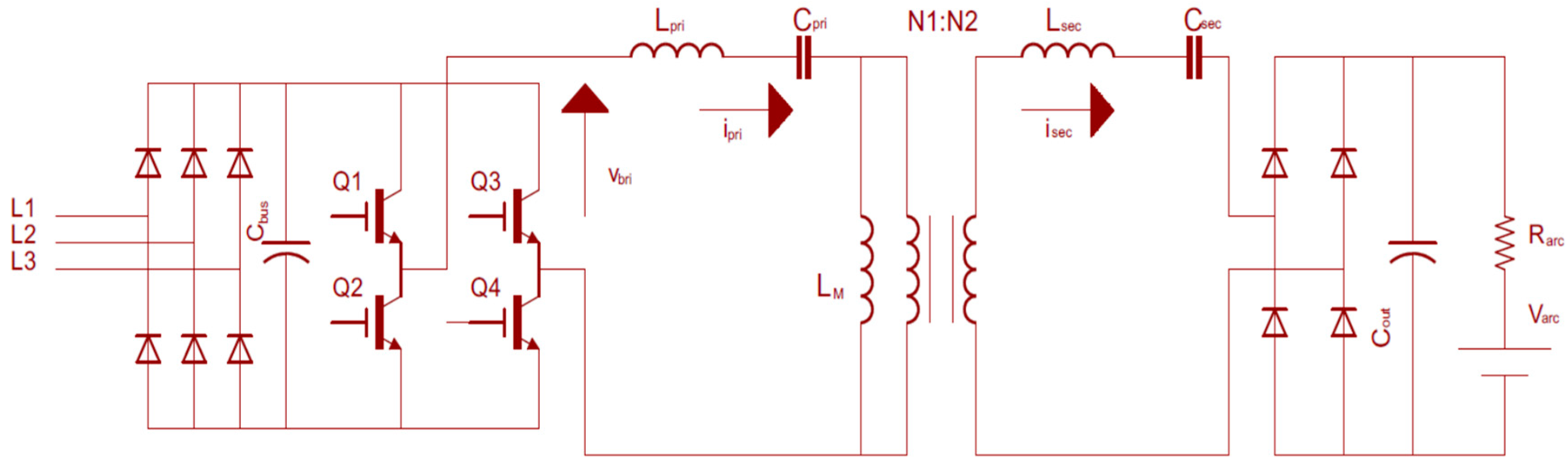
The frequency response of the SRC is that of the band-pass filters in that it allows only the resonant frequency component of the current to pass through while significantly attenuating the other order harmonics [4,6]. Figure 1 shows the circuit diagram of a welding machine including a full-bridge SRC. The welding arc is modeled with a series connected resistor and voltage source [5]. The three-phase rectifier converts the AC power from grid to DC voltage, which is then converted to high-frequency ac voltage by an H-bridge inverter, feeding a resonant network. The resonant frequency of the system is determined by and . The other components make up the band-pass filter. These passive components can be optimized with simple equations.
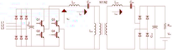
Figure 1.
Schematic diagram of a series resonant converter (SRC).
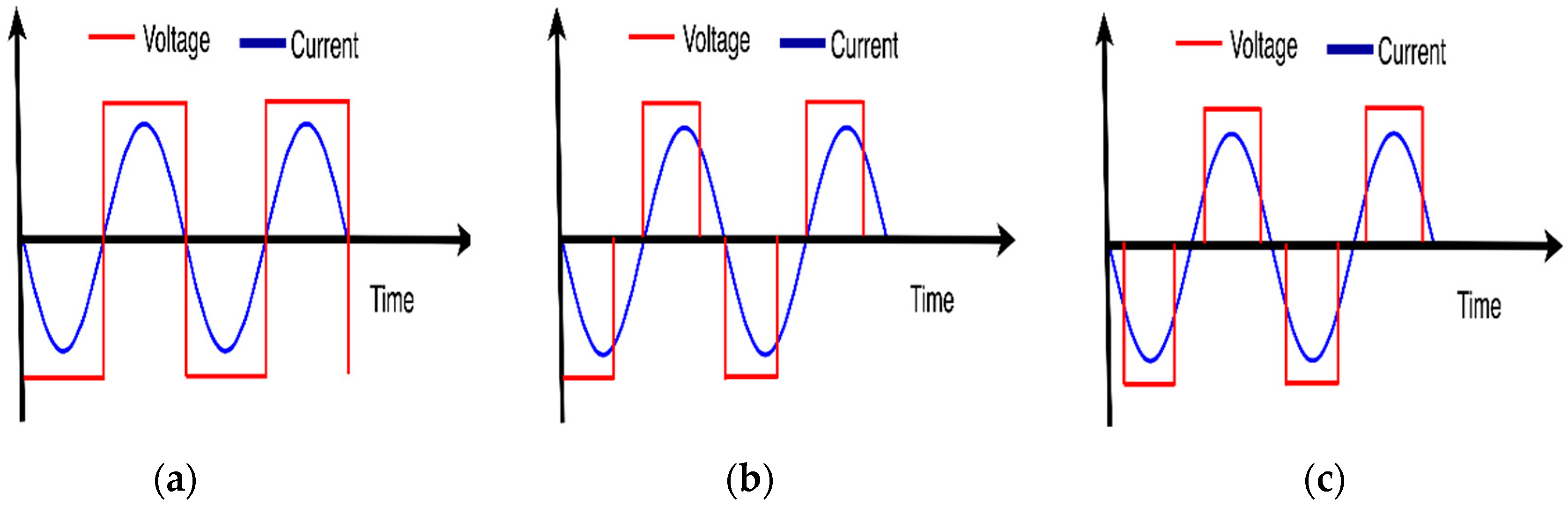
Although the efficiency of the SRC is high around full load conditions, it deteriorates at light loads for which the switching frequency needs to be increased above the resonance frequency, increasing the switching losses. Many methods have been proposed to achieve higher efficiency at low load conditions [7,8]. However, all these methods suffer from a similar problem: losing the soft switching property at turn-on, or at turn-off, or both, nullifies the advantages of soft switching. These cases are illustrated in Figure 2. When the converter operates at full load (Figure 2a) voltage transitions and current transitions occur at the same time leading to soft switching. When the converter operates at partial load, the turn-on may use zero-current switching but turn-off may use hard switching as shown in Figure 2b, or both turn-on and turn-off may use hard switching as shown in Figure 2c.
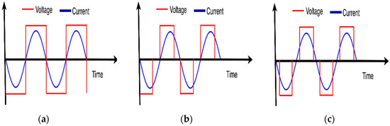
Figure 2.
Simplified SRC switching waveforms. (a) Operation at full load, (b) soft switching at turn-on, hard switching at turn-off, and (c) hard switching at both turn-on and turn-off.
Power transfer via harmonic currents is a technique that utilizes different current harmonics such as 3rd, 5th, 7th, 9th, etc., successively at one period to regulate output power to achieve soft switching. In [4,6] this technique was proposed for electrical vehicle charging systems as an application of wireless power transfer with an efficiency of 83% for a 1 kW system. A similar concept called burst mode or bang-bang control was used to improve the efficiency of the resonance converter at light load [9,10,11]. However, they do not present results for a wide load range.
This paper presents the design and application of a 5 kW SRC GMAW welding machine utilizing the harmonic currents technique for power transfer. The soft switching is achieved both at turn-on and turn-off for a wide range of load. It has been observed that the efficiency of the machine has been improved and the size has been reduced.
The remainder of the paper is structured as follows. In the next section the GMAW system is explained and its model is presented. In Section 3 the full bridge SRC and its band-pass filter behavior are discussed. Then, the proposed method is explained in Section 4. Section 5 is about the design of the converter and its controller. Results obtained at the prototype set-up are presented in Section 6.
2. Load Behavior of the GMAW System
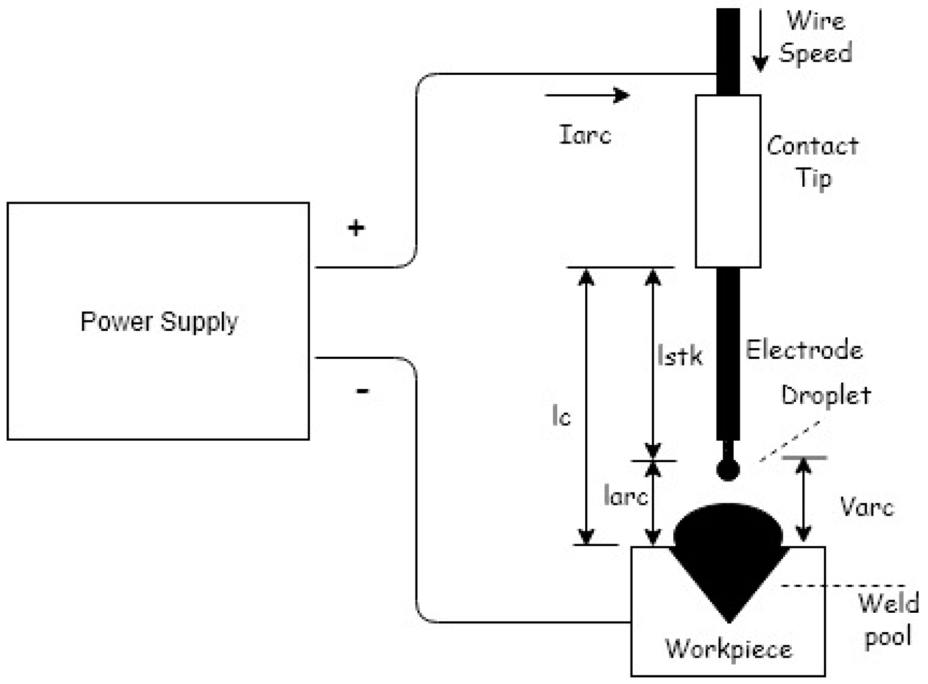
GMAW is one of several types of welding methods. It is highly efficient and it can be used to weld any material of any thickness in any position with the possibility of automatic implementation. GMAW nowadays is considered the most popular type of arc welding process [3,12,13]. Figure 3 shows a schematic that represents the GMAW process.
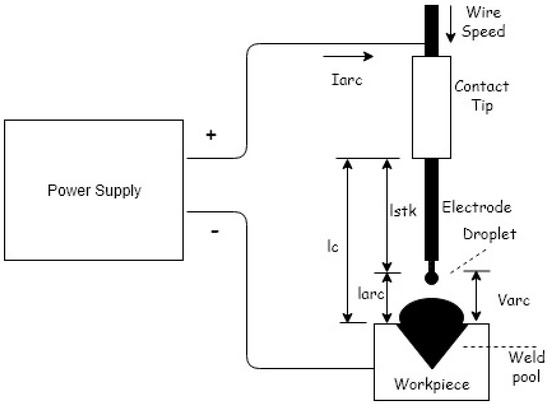
Figure 3.
Electrical model of the gas metal arc welding (GMAW) process.
2.1. Modeling of the GMAW Process
The welding machine for GMAW includes a DC power source. The positive terminal of this power source is connected to the welding electrode while the negative one is connected to the workpiece or vice versa. At the steady state when the arc current and the arc length ( are positive, the arc voltage () and arc power functions that generate arc energy for making a metal joint can be expressed as follows [3,12,13,14]:
The power arc () can be expressed as:
The four distinct parameters of an arc are the constant charge zone voltage (), which is the sum of cathode and anode drop voltages that are considered constant, the arc length (), the arc length factor (), and the arc resistance (). The distance between the contact tube and base plate () is the sum of the arc length () and stick out distance () as shown in Figure 3.
To define the load voltage and power of the system the electrode resistivity () needs to be known. The load voltage () and load power () are given as follows [12,14]:
To define the wire feed speed (), the electrode melting rate () and the rate of change of electrode stick out should be known.
where is quantity of heat needed to melt one gram of weld metal, is the density, is the dimeter of the wire, and is the heat transfer efficiency of the process. Equation (6) can be re-written as:
where and are constant for a specific operating set up.
2.2. Conventional Load Regulation
In general, there are two types of regulations in welding machines: constant voltage (CV) and constant current (CC) mode regulations. In CC mode machines the current affects the melt-off rate or consumption rate of the electrode, whether it is a stick electrode or wire electrode. The higher the current level, the faster the electrode melts or the higher the melt-off rate. In CV mode machines, the voltage controls the length of the welding arc, and the resulting width and volume of the arc cone. As the voltage increases, the arc length gets longer. Table 1 summarizes the recommended output types by welding process [12,15].

Table 1.
Recommended power source output type by arc welding process [15].
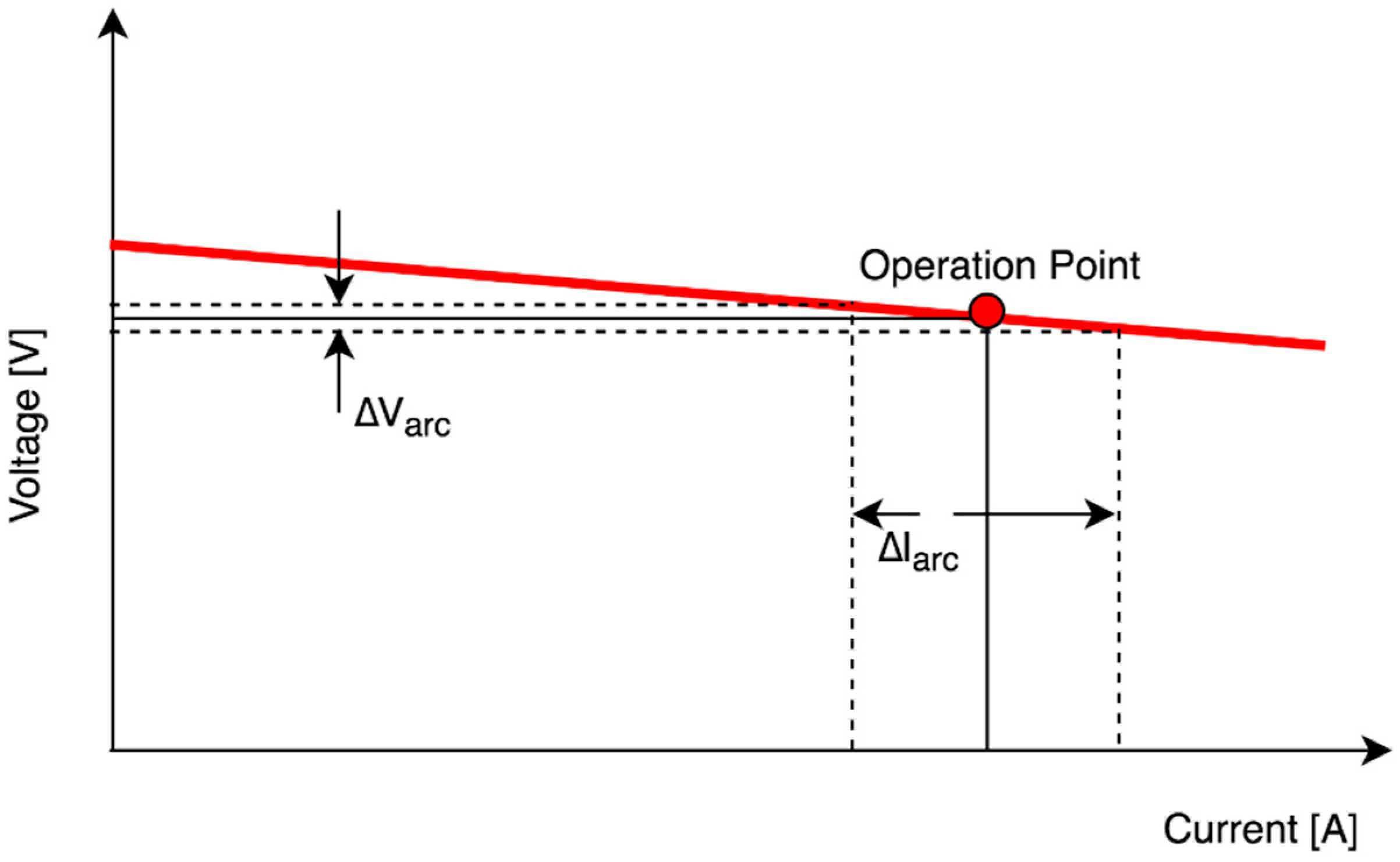
Figure 4 shows the typical output curves of a CV GMAW which is chosen in this work. The voltage stays in a narrow band although the current may vary by a large range.

Figure 4.
GMAW constant voltage curve.
3. Basic Operation Principles of a Series Resonant Circuit
3.1. Band-Pass Filter Characteristic of the SRC
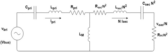
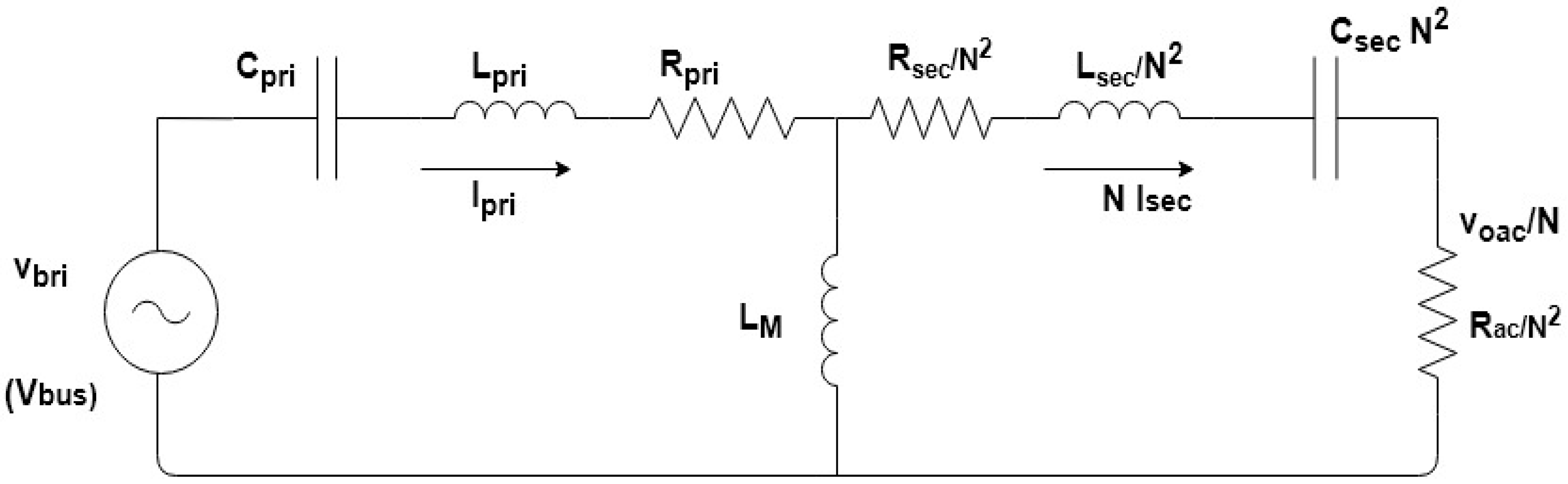
Figure 5.
Equivalent circuit of the SCR full bridge welding machine.
In this equivalent circuit the input AC voltage source () represents the output voltage of the full bridge and is the equivalent AC resistance of the load () seen from the input side of the output rectifier, and it is given as follows:
is the turns ratio of the transformer, is the primary coil AC resistance, and is the secondary coil AC resistance. and are assumed in this analysis. and are the compensation capacitances that determine the resonant frequency by compensating for the leakage inductance. All parameters on the secondary side of the transformer are reflected in the primary. The analysis of the SRC can be performed using this equivalent circuit [16].
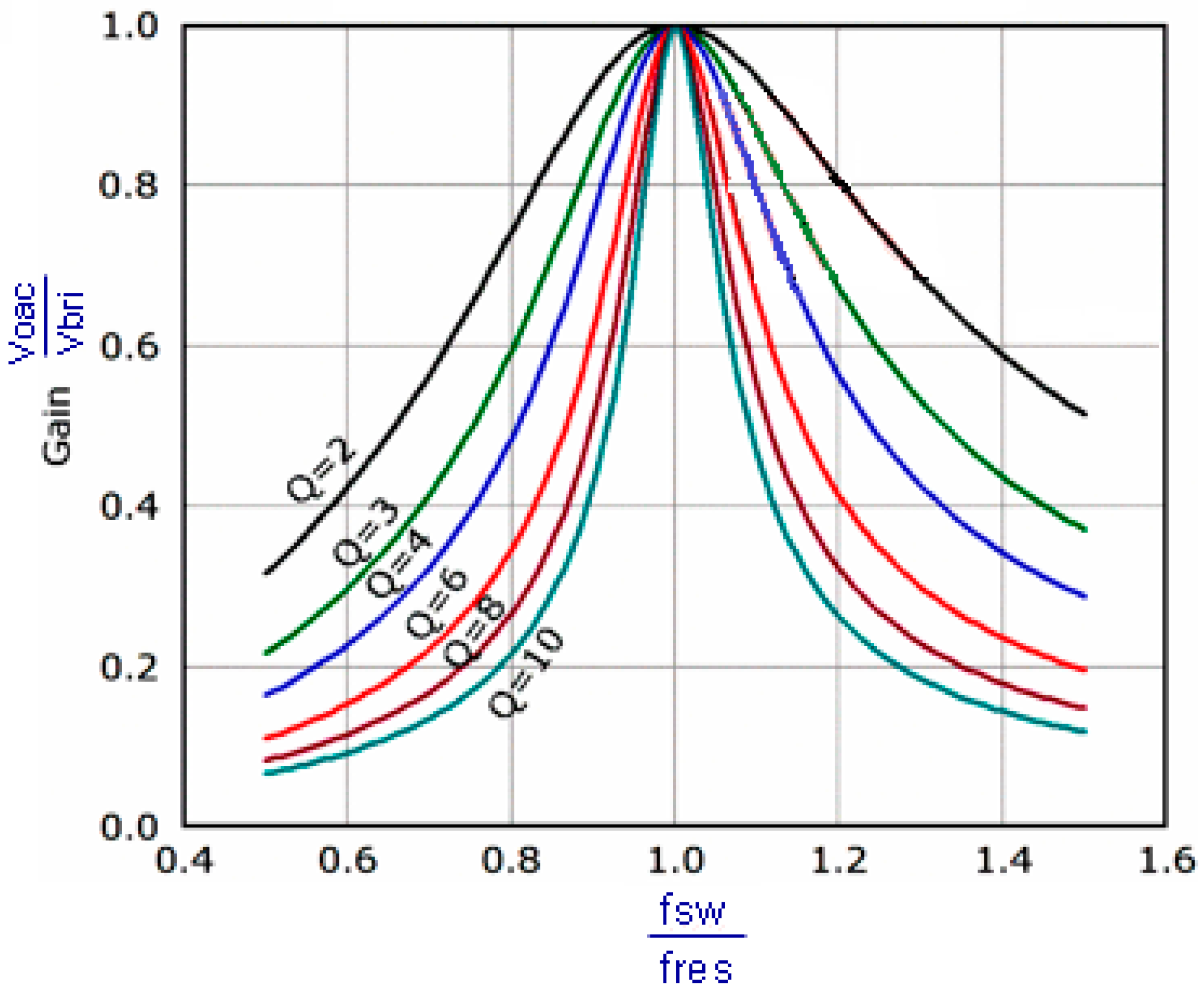
The maximum transfer gain is achieved when the input switching frequency () is equal to the resonant frequency () where the voltage appears across the load (). The voltage gain then can be defined in terms of the RMS voltages of the output and input as:
In this equation, is the quality factor and is defined as:
For the SRC this equation can be written as follows:
where .
Figure 6 shows the voltage gain frequency variation with the quality factor used as a parameter [16,17].

Figure 6.
Band-pass filter characteristic and gain curve.
3.2. Control of Power Through Harmonic Components
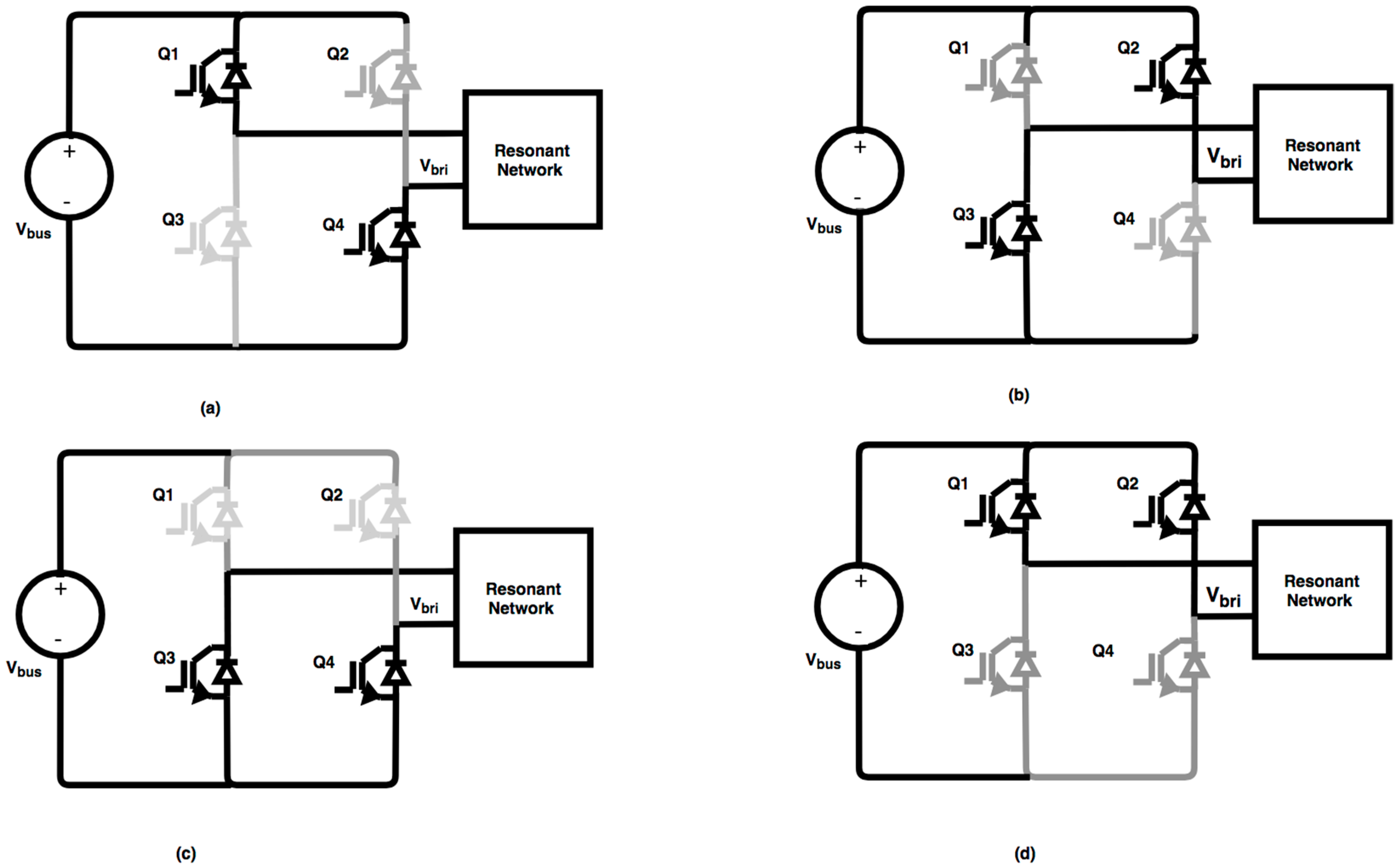
As shown in Figure 7, the H-bridge inverter has three modes of operation: it generates positive voltage () when Q1 and Q4 are on, negative voltage () when Q2 and Q3 are on, and zero voltage () when either Q1 and Q3 or Q2 and Q4 pairs are on. The last two modes can be called the circulation modes. The first two modes are initiated when diagonal switches are turned on creating a resonant pulse train. At the end of the first pulses these modes end, and circulation modes start. In circulation modes pulses continue to flow through the load [18].
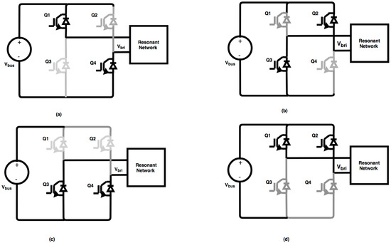
Figure 7.
Switching modes of the SCR full bridge (a) and (b) active modes, (c) and (d) zero states.
Figure 8 shows the output voltage waveforms of the H-bridge () and its harmonic components. D is the duty cycle defined as the ratio of the on time switches to the half period (D). The phase shift between the two legs controls the RMS output voltage of . Fourier series expansion of this voltage is given as [1]:
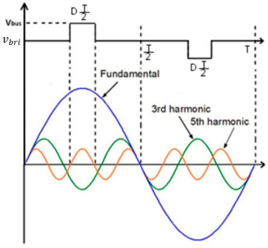
Figure 8.
Output waveforms from the H-bridge and the harmonic component.
Due to the band-pass filter feature of the resonant network, only the resonant frequency component of can pass to the secondary side of the converter, with all other frequency components filtered out by the large impedance.
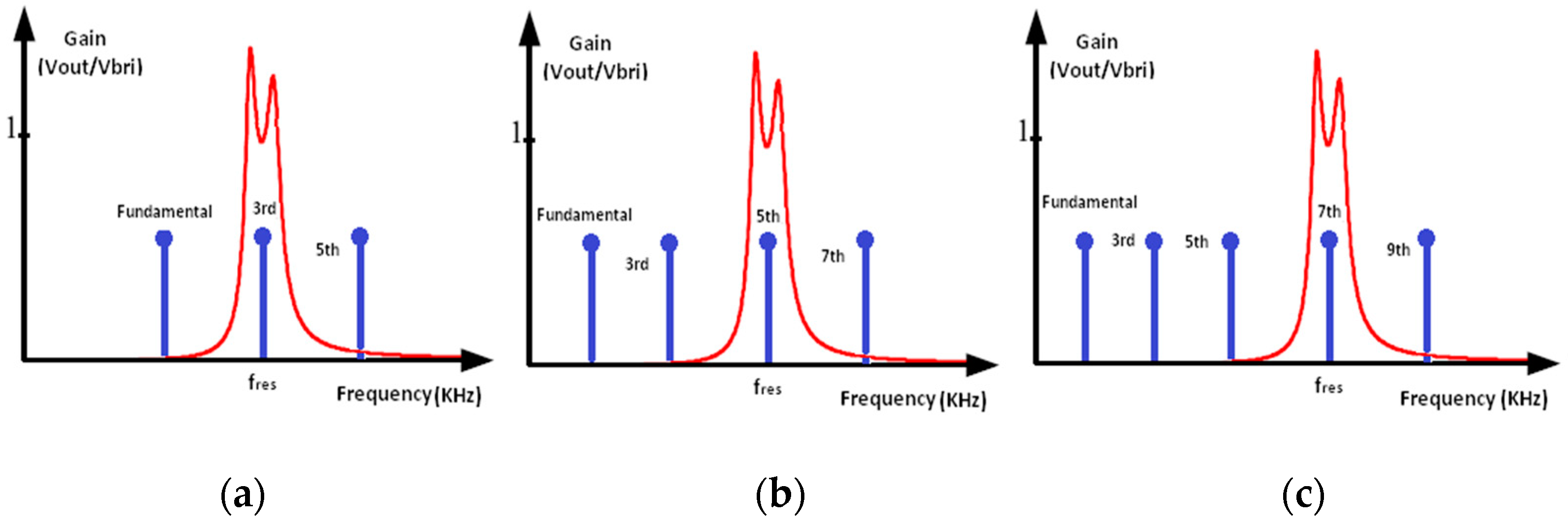
The power control in this circuit is achieved by changing the switching frequency of the SRC in such a way that it is equal to , , etc. If the required power is low, the switching frequency is adjusted to a lower value so that a very high order of harmonic is at the resonant frequency. In this case, the value of the voltage harmonic at the resonance frequency is low, generating low power. For full power, the highest possible switching frequency () is selected. In this case, the third harmonic of the voltage determines the power. This concept is depicted in Figure 9 for a system using three different switching frequencies for three specific power levels. Figure 9a shows the case for the highest power for which the switching frequency is equal to 1/3rd of the resonant frequency. In Figure 9b, a lower power is required and switching at 1/5th of the resonant frequency produces a 5th harmonic voltage whose RMS value is 1/5th of that of the fundamental. Figure 9c shows the case when the power demand is the lowest. Switching at 1/7th of the resonant frequency produces a 7th harmonic voltage whose RMS value is 1/7th of that of the fundamental.
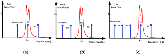
Figure 9.
The principle of power control by harmonic components.
If a power level between the specific levels is required, then switching frequencies corresponding to the two neighboring levels are alternately used for a calculated length of time. For example, for a power level between the medium power and the full power, a number of pulses is applied for and a number of pulses is applied for . The required numbers should be calculated by the controller.
For fine power control, the number of switching frequencies can be increased and much lower switching frequencies can be used.
4. Design of the SRC Converter and its Controller
Nowadays GMAW welding machines have new technology called “smart MIG (Metal Inert Gas)”. With smart MIG technology, users choose variables such as material thickness, material type, welding wire diameter, isolated gas used, and the value of arc voltage (), arc current, and the speed of wire feeding () are determined automatically by using a look-up table.
A 5 kW GMAW welder utilizing an SRC converter has been designed for this work. The input is a 380 Vrms, 50 Hz AC source. The output voltage can be adjusted between 18 and 30 V. Technical specifications of the designed system are given in Table 2.
Table 2.
Parameters of the designed GMAW machine.
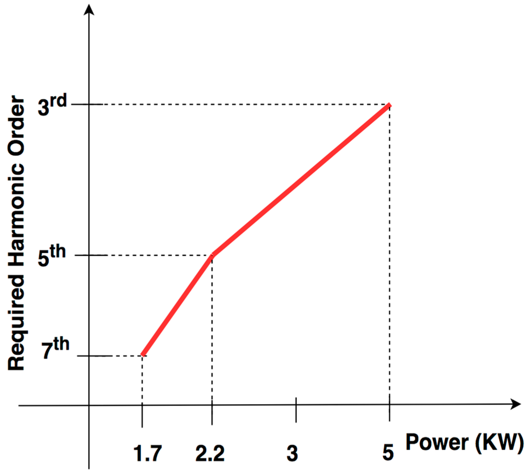
The control circuit of the system was designed to achieve constant voltage by charging the output capacitor Cout by using the harmonics-based control method. Figure 10 shows which harmonic order is used for which required power level.
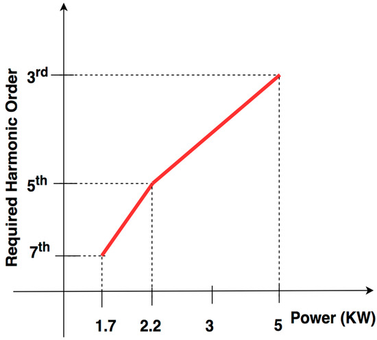
Figure 10.
Harmonic order–power level match for the designed system.
5. Simulation Results
Simulations have been carried out in PSIM to see the operation of the system. Table 3 shows the parameters of the welding components used in the system modeling.
Table 3.
Parameters and some variables of the GMAW process model used in the simulations for carbon steel [13].
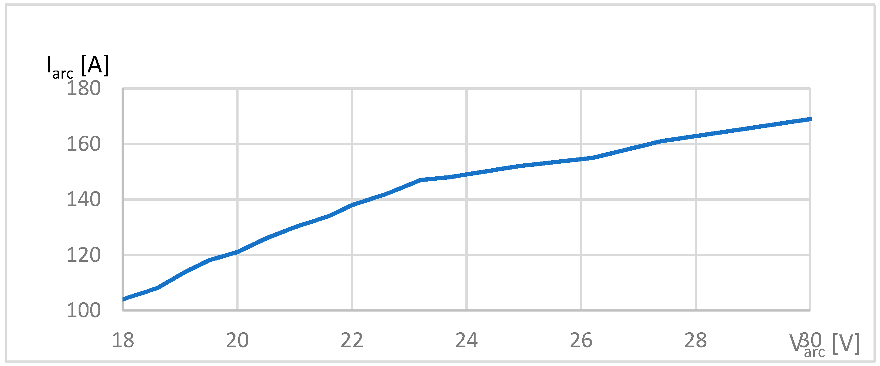
The arc current–arc voltage relationship has been obtained for these parameters as shown in Figure 11. As seen in the graph the variation is linear in the designed operation range.
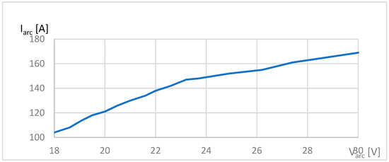
Figure 11.
Arc voltage–arc current relationship for the designed machine.
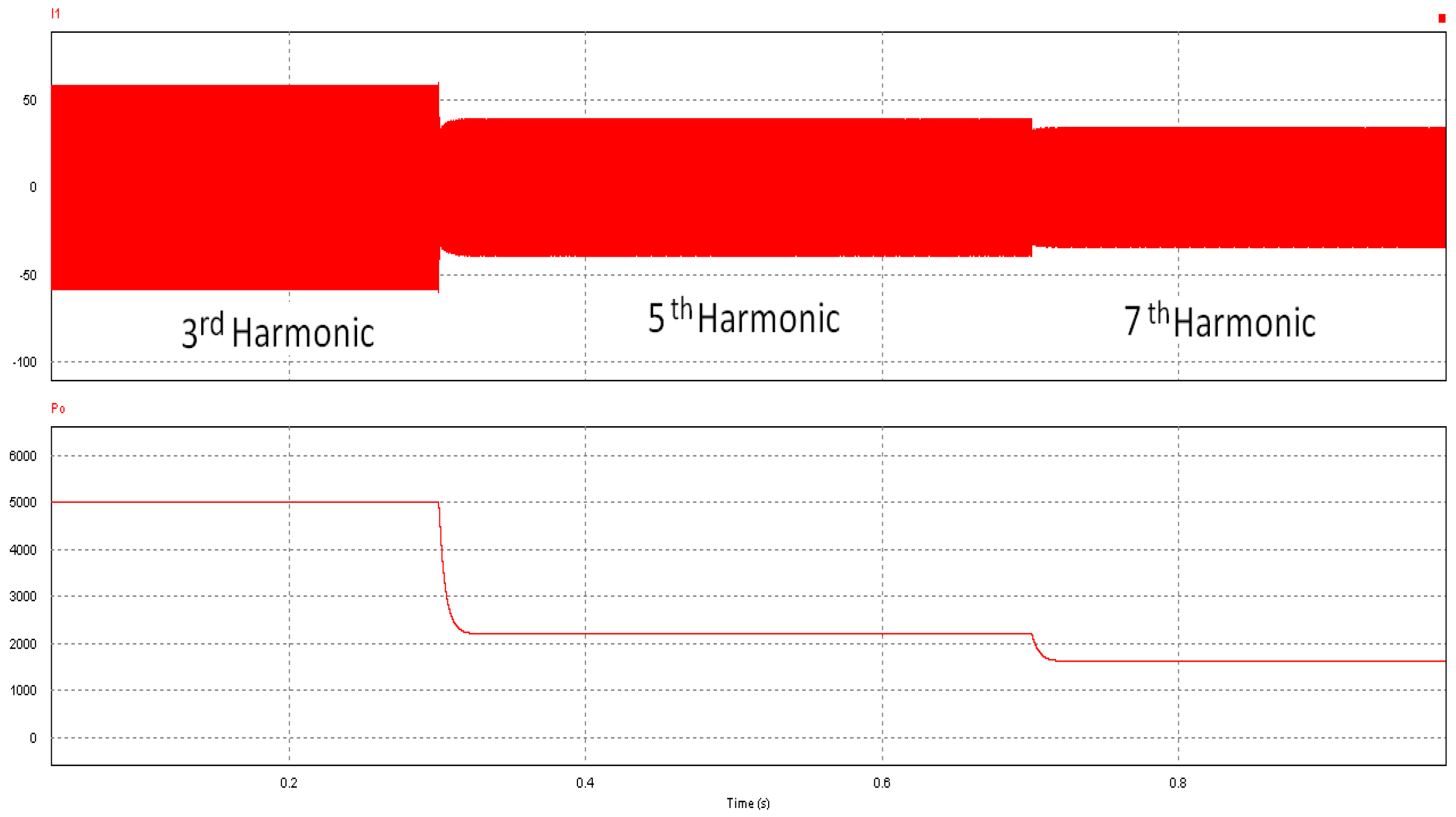
The system has been designed to have the harmonic order–power profile as shown in Figure 12. For full power the third harmonics (5 kW), for medium power (2.2 kW) the fifth harmonics, and for low power (1.7 kW) the seventh harmonics are used.
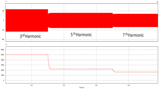
Figure 12.
Harmonic order–power relationship for the designed system: Primary current (upper trace), load power (lower trace).
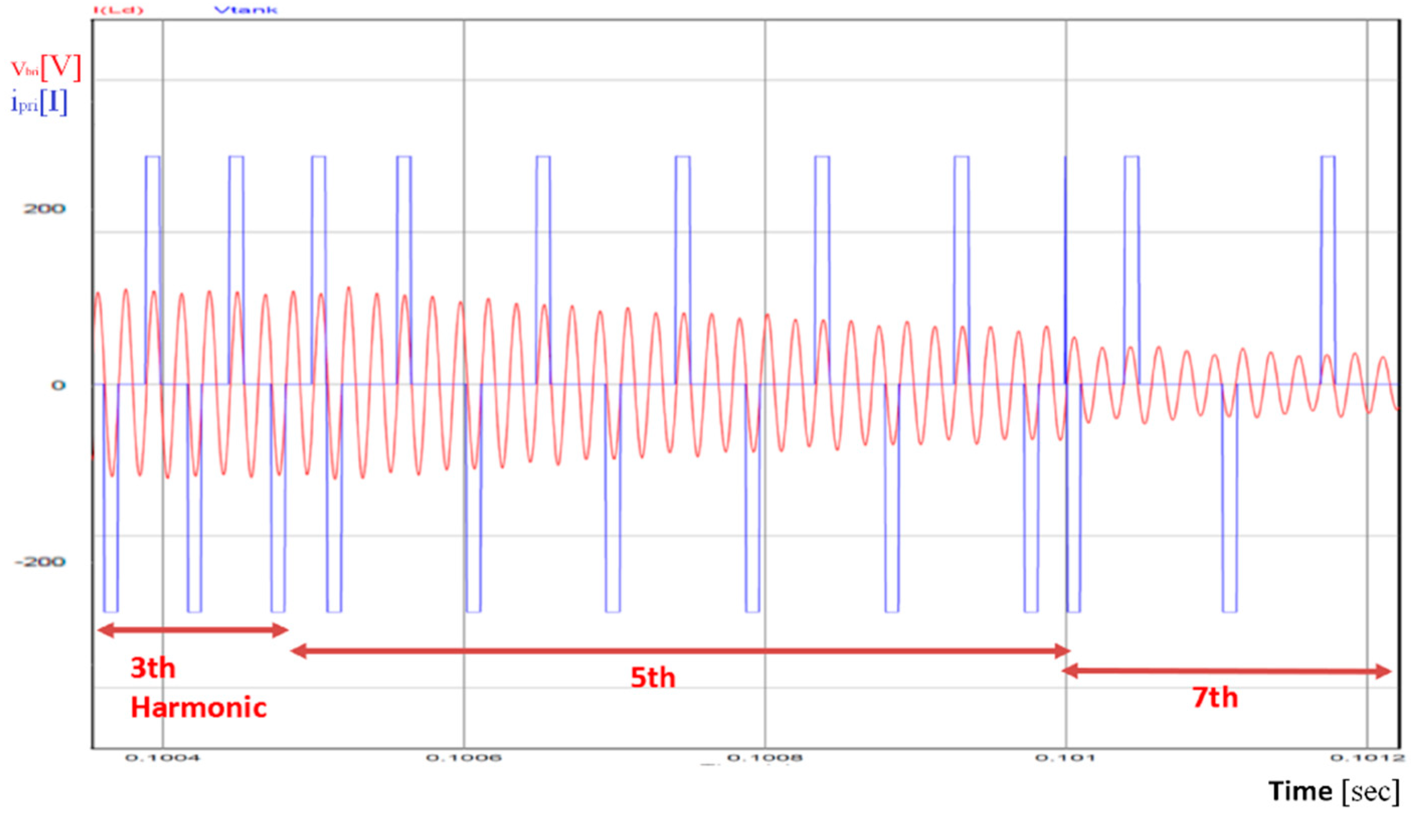
Figure 13 shows the bridge output voltage and current pulses. First, the switching frequency is 1/3rd of the resonant frequency and therefore the 3rd harmonic current passes through. Then 1/5th and 1/7th of resonant frequency are used for switching, respectively, yielding the 5th and 7th harmonic currents to transfer the power. Soft switching is achieved at each turn-on and turn-off.
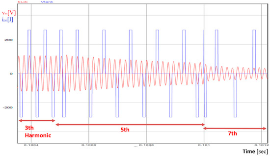
Figure 13.
Bridge output voltage and primary current.
The resonant frequency depends on the value of the passive components. The time that needs to return to zero is half of the resonant period (). In order to achieve soft switching, the switch on time condition has to be met. This is adjusted by the duty cycle of the switch as the switching frequency is changed.
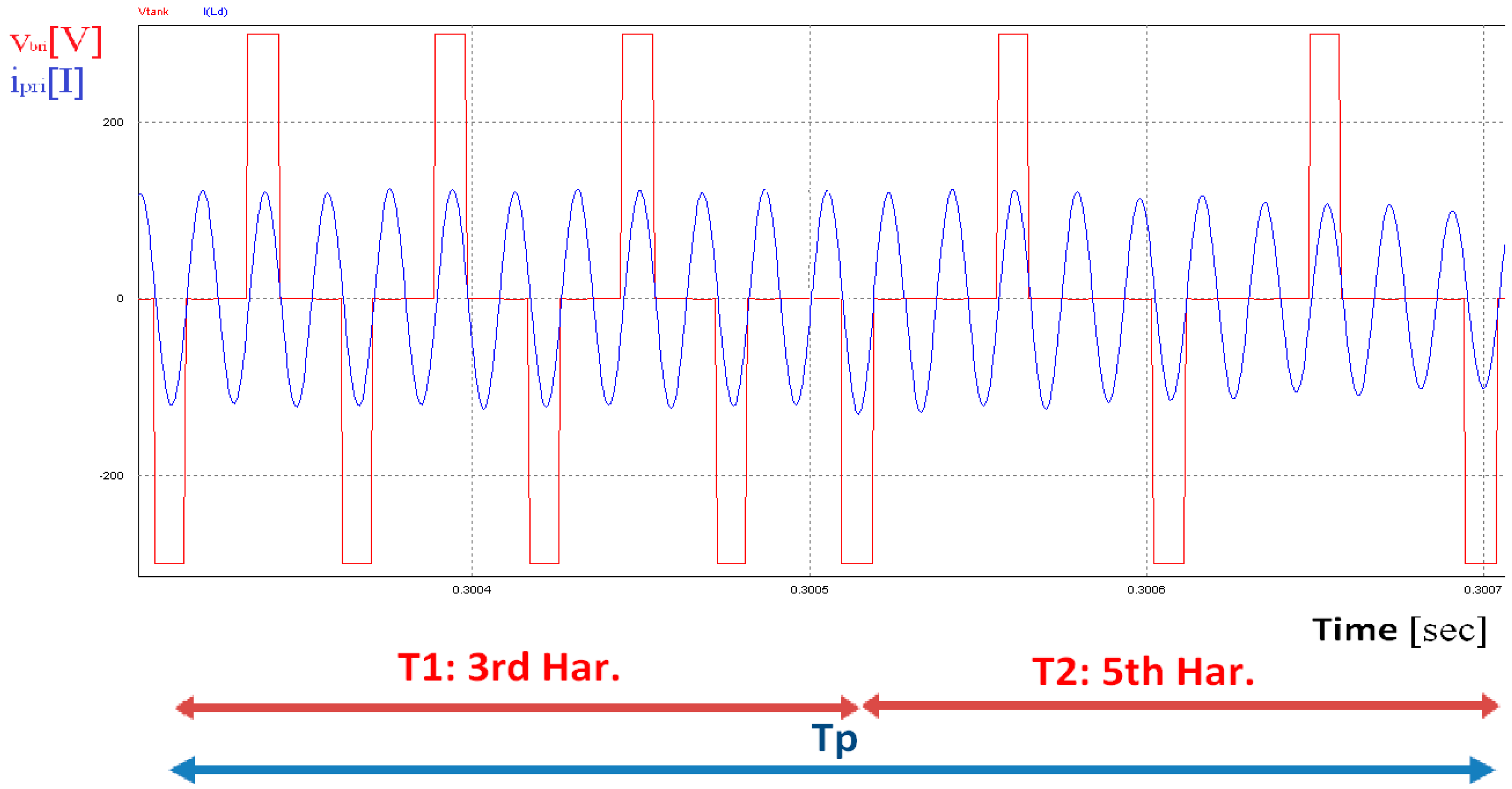
Figure 14 shows how the power is regulated. If a power level other than the specified levels is required, two different switching frequencies are used alternately in a period of regulation () where and are the corresponding application times of each frequency generating the desired harmonics at the resonant frequency. should be significantly larger than the switching frequency, and smaller than the system response frequency. In this figure, the 3rd harmonic and 5th harmonic currents are generated to obtain the required power.
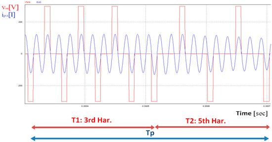
Figure 14.
Example of power period Tp (PSIM simulation program was used).
6. Loss Analysis
6.1. Transformer Loss Calculations
There are two kinds of losses in the magnetic components like the inductors and the transformers: core losses () and copper losses (). The total losses for a transformer can be calculated as [19,20]:
6.1.1. Copper Losses
If the primary and secondary currents are known copper losses can be calculated using the following equation:
As the load becomes lighter the copper losses decrease.
6.1.2. Core Losses
The Steinmetz equation is used to determine the core losses of magnetic components [19,20].
is the peak flux density and , , and are material parameters. In this work a ferrite EE80 core is used and the material parameters are taken from the manufacturer’s material specifications.
The parameters for the magnetic components of the system are given in Table 4.
Table 4.
Parameters of the magnetic components.
It should be mentioned that as the core losses depend on the applied voltage, they are almost constant at constant-voltage, constant-frequency applications. However, in the application described in this paper, as the load becomes lighter, the switching frequency is reduced leading to lower voltages across the transformer. While the frequency is constant at the resonance frequency, the reduced voltage leads to reduced flux and therefore core losses are lower at light load.
6.2. Semiconductor Losses
The semiconductor losses can be calculated by using the technical information given in manufacturers datasheets. The designed circuit in the primary stage has six line-rectifier diodes and four inverter IGBTs. The secondary stage has four high frequency rectifier diodes.
There are two types of losses in an IGBT: conduction losses () and switching losses (). The total loss equation is given in (16).
where is the voltage across the device at the off state, is the current level at the on state, is the voltage across the device at the on state, is the rise time of the current, is the fall time of the current, and is the duty cycle ratio of the switch. If the inverter is operating at resonance conditions, the switching losses can be ignored.
Primary diodes rectify at 50 Hz, and therefore reverse recovery losses can be ignored. Total loss from primary diodes can be calculated as:
Secondary side rectification diodes rectify at high frequency so reverse recovery losses are dominant.
In this equation is the diode reverse recovery time.
The device parameters are listed in Table 5.
Table 5.
Parameters of the semiconductor devices.
It should be mentioned that while the switching losses are reduced as the load becomes lighter at constant-voltage, constant-frequency applications, they are almost ignorable in this application due to near zero-voltage-switching (ZVS) switching as well as reduced switching frequency.
6.3. Other Losses
Other parasitic losses exist within the system, like capacitor equivalent series resistor (ESR), particularly for high current systems. Capacitors are important for maintaining waveform quality and reducing voltage spikes and ripples and ESR losses can become significant when the current is large.
Another type of loss that is difficult to estimate is due to the parasitic inductance of cables, wires, etc. Parasitic inductance can cause excessive voltage spikes during switching. Switching the waveforms affected will result in larger losses in addition to higher voltage stress. Termination and mechanical connections are another major parasitic loss, especially for high current situations.
7. Experimental Results
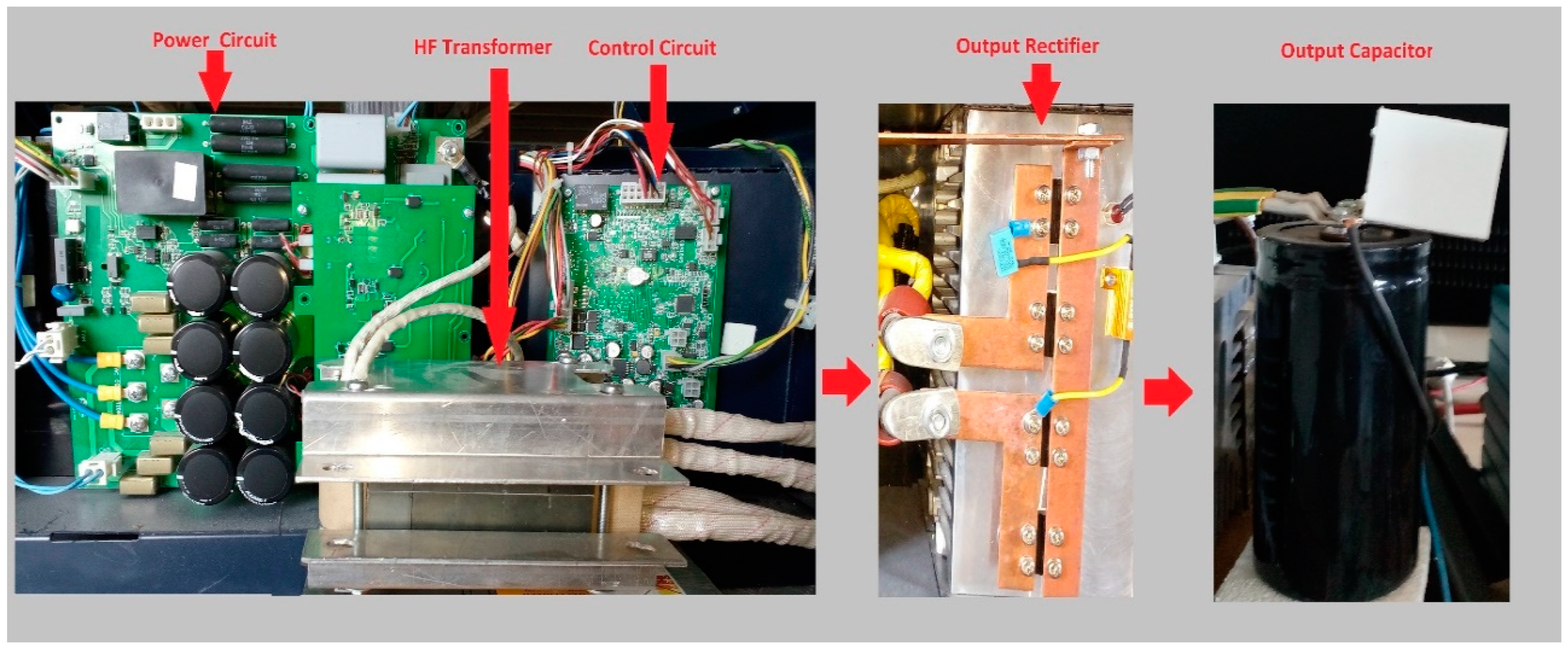
The designed system has been built and tested. The experimental 5 kW set-up is shown in Figure 15. DSPIC33EP128GS806 has been used as the core of the control circuit. The full-bridge is composed of four IGBTs (Semikron SKM200GB125D) that work with the resonant converter up to 100 kHz, and a Ferroxcube E80/38/20 (3C94) ferrite core for high frequency transformers and the two resonant inductors.

Figure 15.
Experimental circuit of the SRC GMAW welding machine.
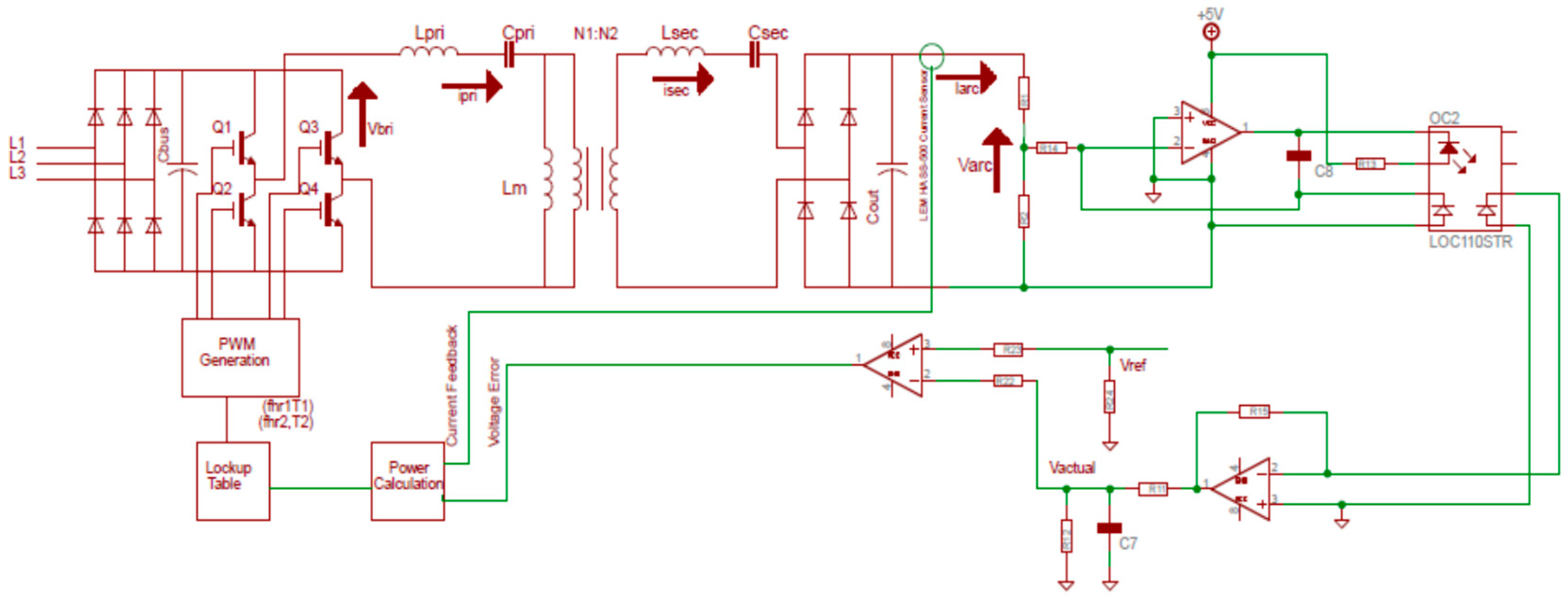
Figure 16 shows the complete control diagram of the resonant welding machine. The output voltage is fed back by using an isolated voltage sensor. is the value of the arc voltage that is set by users according to the welding parameters between 18 V and 30 V. The look-up table data is calculated offline and every value of power has harmonics data (frequencies, time of harmonics).
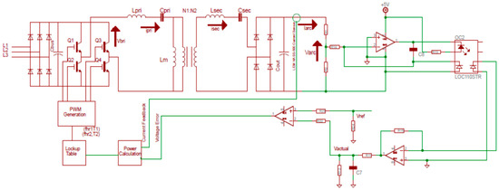
Figure 16.
Control circuit of the SCR GMAW converter.
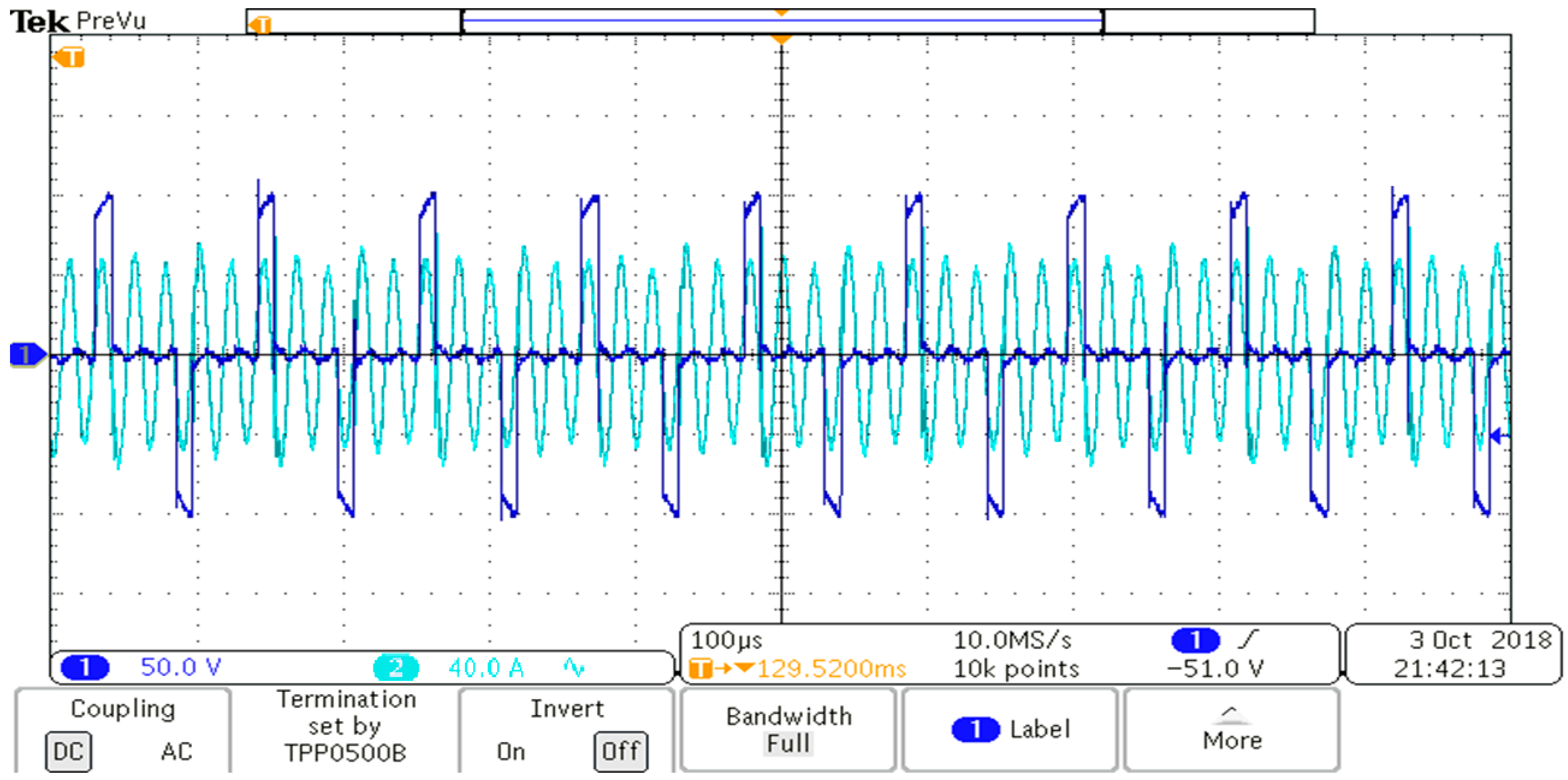
Figure 17 shows the output voltage of the bridge and primary resonant current waveforms when the converter is controlled by the harmonic current at full load. Soft switching is obvious at both turn-ons and turn-offs. The output voltage is constant at 30V ± 1V and the current is around 165 A.
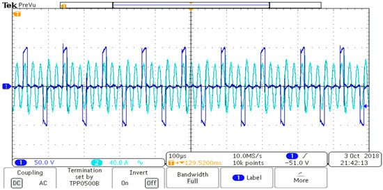
Figure 17.
Full load operation (3rd harmonic control) signals (Ch.1: bridge voltage () and Ch.2: primary current ()).
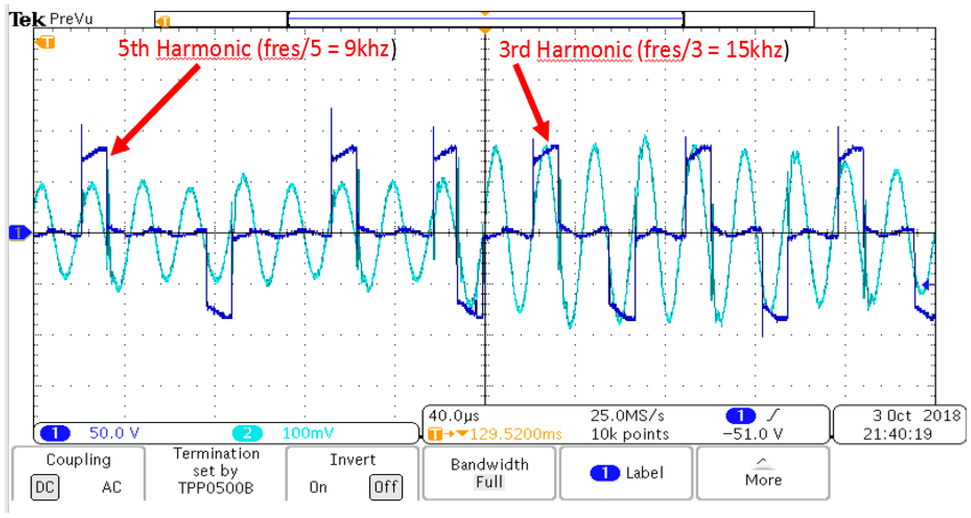
Figure 18 shows the output voltage of the bridge and primary resonant current waveforms at 60% load. Waveforms have the 3rd and 5th harmonics as expected. The power is estimated by the feedback of the current and voltage and the required percentages of each harmonic (switching frequency) for one full period () is determined by using the look-up table.
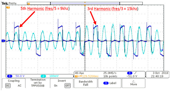
Figure 18.
Third and 5th current harmonics signals at 60% load (Ch.1: voltage () and Ch.2: current ()).
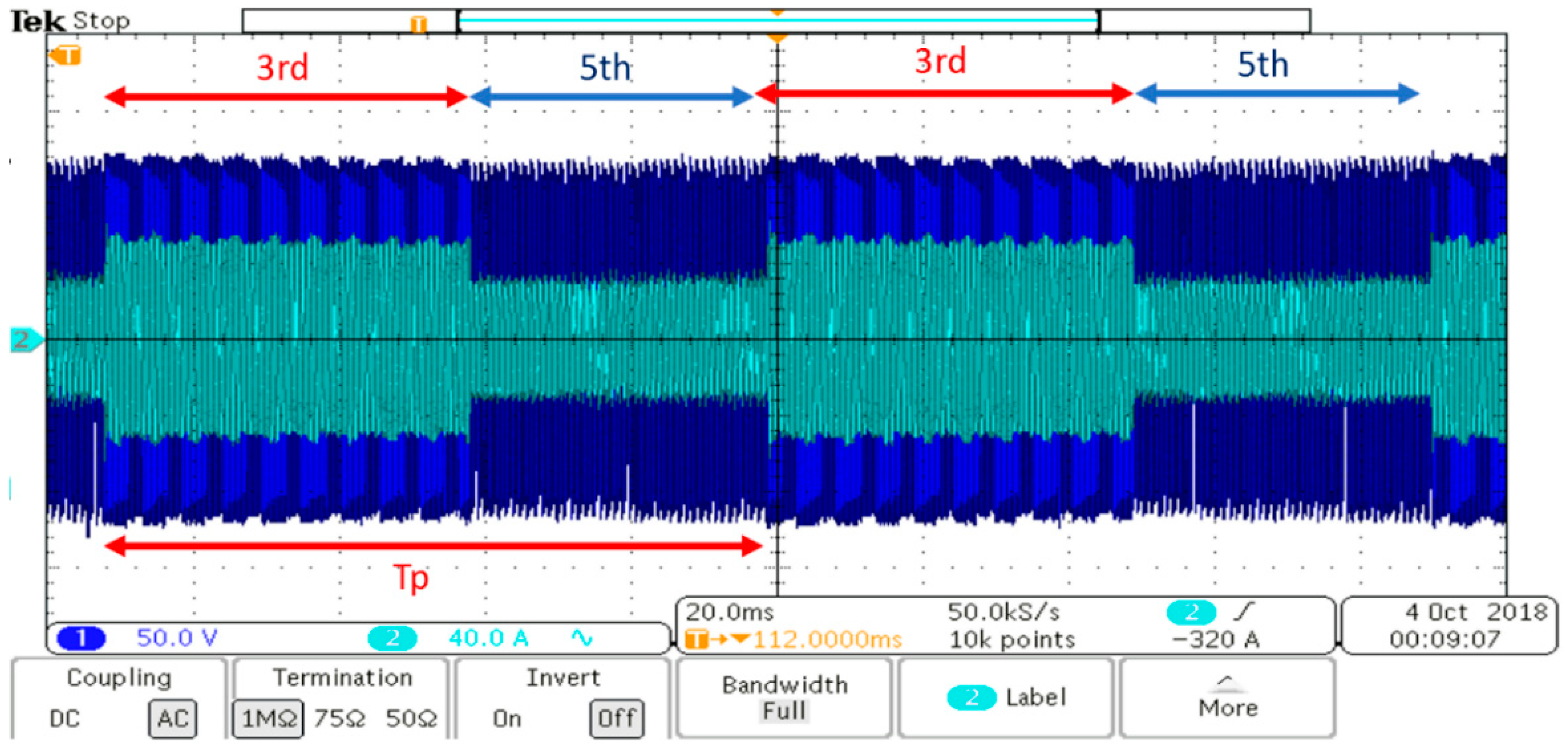
Figure 19 shows operation at 60% load for the full period for the waveforms in Figure 18. A combination of the 3rd and 5th harmonics is used to meet this load demand. The percentage of each harmonic changes as the load demand changes. Figure 20 shows the operation at 40% load for which a combination of the 5th and 7th harmonics is used.
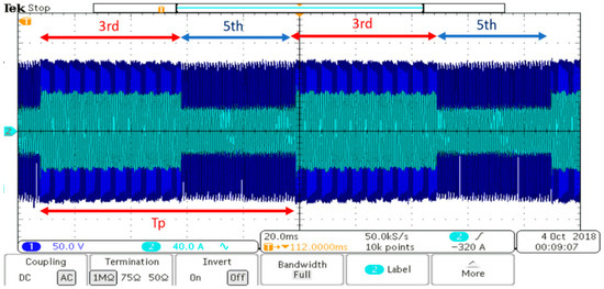
Figure 19.
Operation at 60% load with a combination of the 3rd and 5th current harmonics (Ch.1: voltage () and Ch.2: current ()).
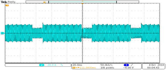
Figure 20.
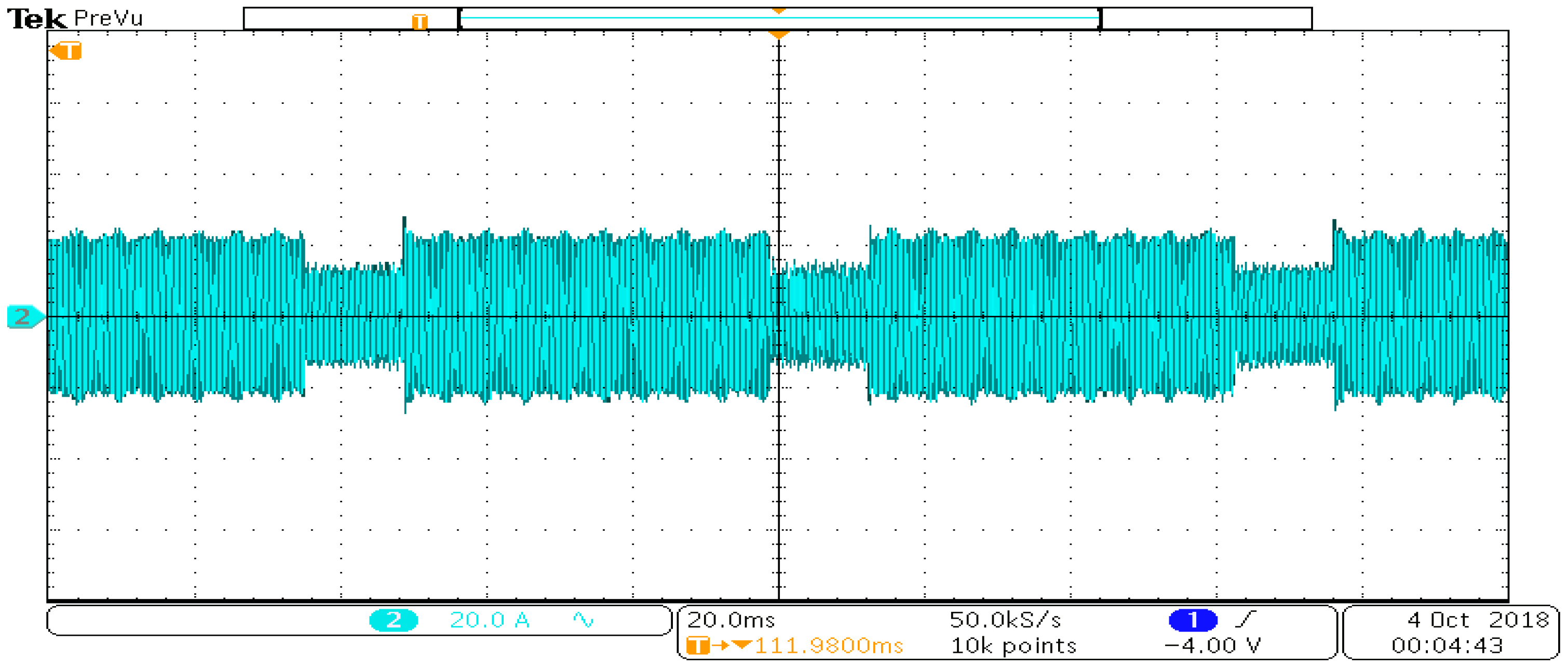
Operation at 40% load with a combination of the 5th and 7th current harmonics (Ch.2: current ()).
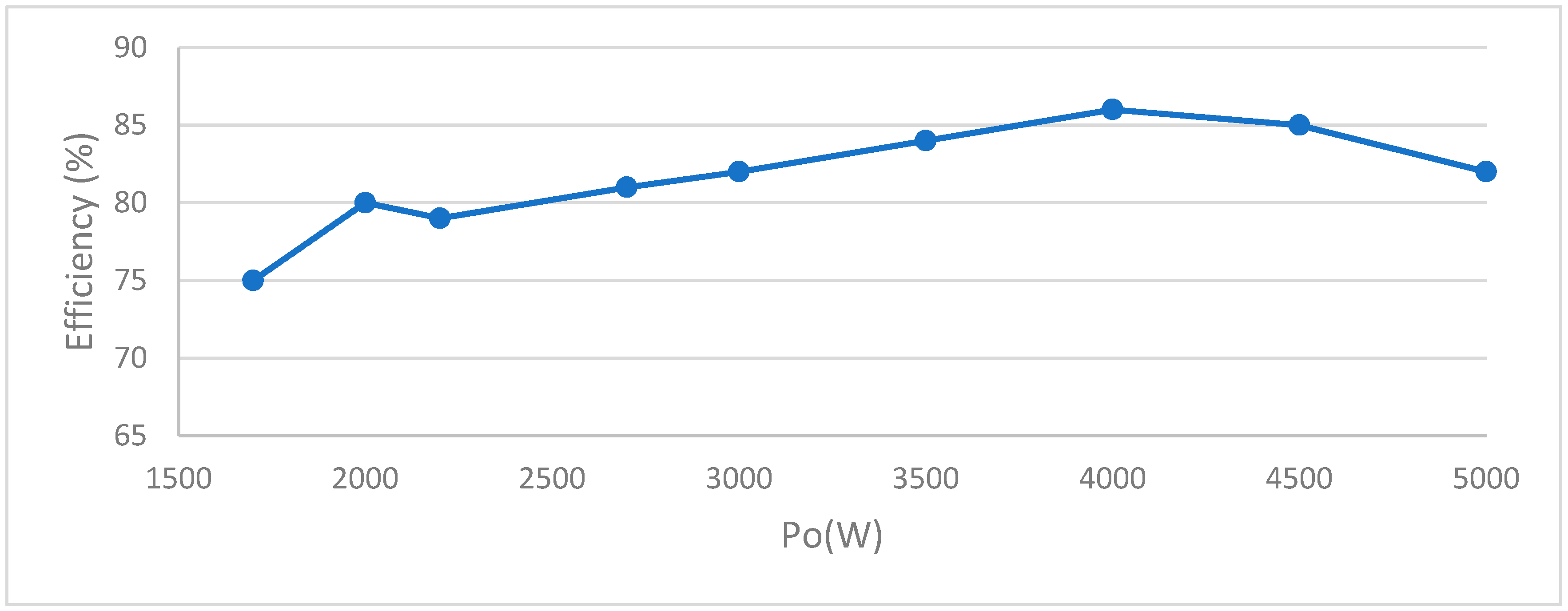
The efficiency of the designed system of the SRC converter welding machine with the proposed control technique was measured practically by a three phase power quality analyzer (Fluke 435) at different values of the output power. The maximum efficiency was obtained at 80% to approximately 86% load as shown in Figure 21. Table 6 shows the measured losses as well as the calculated ones. For welding machine efficiencies, around 80% is acceptable in industry applications [21,22].
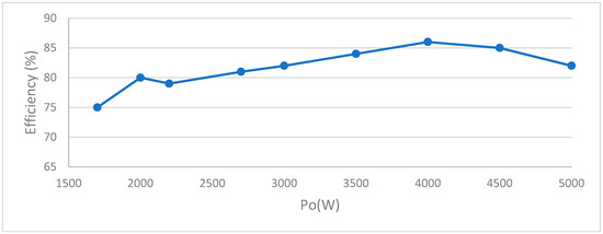
Figure 21.
Experimental result of efficiency for output power between 1.7 kW and 5 kW.
Table 6.
Losses cause by system at 86% efficiency.
Compared to the constant switching frequency of hard switched cases, the advantages of this technique come from two different areas: (a) soft switching at both turn-on and turn-off, and (b) reduced core losses at light load as the switching frequency has to be reduced. However, the efficiency can be improved further by optimizing the remaining system, especially the transformer. Thermal losses especially at parts that handle high current like secondary diodes need to be handled better. Since this paper focuses on the control technique, the system was not optimized yet.
8. Conclusions
GMAW welding machines are very commonly used in industry. Reducing the size and weight of these machines requires high switching frequencies. However, the switching frequency is limited by the losses of the devices used in the inverter. This paper proposes a control algorithm that can be used in GMAW machines along with series resonance converters. The technique takes advantage of the band-pass filter-like nature of the converter and uses switching frequencies that are 1/3rd, 1/5th, 1/7th, etc., of the resonance frequency. The switching frequency varies between these discrete values to meet the load demand.
Author Contributions
Writing—review and editing, N.S.A., A.U., and M.T.A.
Funding
This research received no external funding.
Conflicts of Interest
The authors declare no conflict of interest.
References
- Khatamianfar, A.; Fateh, M.M.; Farahani, S.S. On sliding mode control of the manual gas metal arc welding process. In Proceedings of the 2008 IEEE International Conference on Systems, Man and Cybernetics, Singapore, 12–15 October 2008; pp. 3570–3575. [Google Scholar]
- Bazargan-Lari, Y.; Eghtesad, M.; Assadsangabi, B. Study of Internal Dynamics Stability and Regulation of Globular- Spray Mode of GMAW Process via MIMO Feedback-linearization Scheme. In Proceedings of the 2008 International Conference on Intelligent Engineering Systems, Miami, FL, USA, 25–29 February 2008; pp. 31–36. [Google Scholar]
- Anzehaee, M.M.; Haeri, M.; Tipi, A.R.D. Gas Metal Arc Welding process control based on arc length and arc voltage. In Proceedings of the ICCAS 2010, Gyeonggi-do, South Korea, 27–30 October 2010; pp. 280–285. [Google Scholar]
- Zeng, H.; Yang, S.; Peng, F.Z. Design Consideration and Comparison of Wireless Power Transfer via Harmonic Current for PHEV and EV Wireless Charging. IEEE Trans. Power Electron. 2017, 32, 5943–5952. [Google Scholar] [CrossRef]
- Brañas, C.; Casanueva, R.; Azcondo, F.J. Unfolded resonant converter with current doubler structure module for welding applications. In Proceedings of the 2017 11th IEEE International Conference on Compatibility, Power Electronics and Power Engineering (CPE-POWERENG), Cadiz, Spain, 4–6 April 2017; pp. 288–293. [Google Scholar]
- Zeng, H.; Yang, S.; Peng, F. Wireless power transfer via harmonic current for electric vehicles application. In Proceedings of the 2015 IEEE Applied Power Electronics Conference and Exposition (APEC), Charlotte, NC, USA, 15–19 March 2015; pp. 592–596. [Google Scholar]
- Hou, J.; Chen, Q.; Yan, K.; Ren, X.; Wong, S.; Tse, C.K. Analysis and control of S/SP compensation contactless resonant converter with constant voltage gain. In Proceedings of the 2013 IEEE Energy Conversion Congress and Exposition, Denver, CO, USA, 15–19 September 2013; pp. 2552–2558. [Google Scholar]
- Ryu, S.; Kim, D.; Kim, M.; Kim, J.; Lee, B. Adjustable Frequency–Duty-Cycle Hybrid Control Strategy for Full-Bridge Series Resonant Converters in Electric Vehicle Chargers. IEEE Trans. Ind. Electron. 2014, 61, 5354–5362. [Google Scholar] [CrossRef]
- Zhang, X.; Yao, C.; Guo, F.; Wang, J. Optimal operation and burst-mode control for improving the efficiency of the quasi-switched-capacitor resonant converter. In Proceedings of the 2014 IEEE Energy Conversion Congress and Exposition (ECCE), Pittsburgh, PA, USA, 14–18 September 2014; pp. 5444–5450. [Google Scholar]
- Feng, W.; Lee, F.C.; Mattavelli, P.; Huang, D.; Prasantanakorn, C. LLC resonant converter burst mode control with constant burst time and optimal switching pattern. In Proceedings of the 2011 Twenty-Sixth Annual IEEE Applied Power Electronics Conference and Exposition (APEC), Fort Worth, TX, USA, 6–11 March 2011; pp. 6–12. [Google Scholar]
- Hu, Z.; Liu, Y.; Sen, P.C. Bang-Bang Charge Control for LLC Resonant Converters. IEEE Trans. Power Electron. 2015, 30, 1093–1108. [Google Scholar] [CrossRef]
- Paul, A.K. Capability, Flexibility, and Legacy of PI Hinder Market Penetration Prospect of SOSM for Control of GMAW Process. IEEE Trans. Ind. Appl. 2016, 52, 384–394. [Google Scholar] [CrossRef]
- Anzehaee, M.M.; Haeri, M. Welding current and arc voltage control in a GMAW process using ARMarkov based MPC. Control Eng. Pract. 2011, 19, 1408–1422. [Google Scholar] [CrossRef]
- Marjan, G. Integrated Models of a Gas Metal ARC Welding Process and Inverter based Power Supply for Process Control Simulation Studies. Elektronika ir Elektrotechnika 2014, 20, 3–6. [Google Scholar]
- O’Brien, A. Welding Handbook, 9th ed.; American Welding Society: Miami, FL, USA, 2004; Volume II, pp. 147–204. [Google Scholar]
- Nagarajan, C.; Madhswaran, M. Analysis and simulation of LCL series Resonant Full Bridge Converter using PWM technique with load independent operation. In Proceedings of the 2007 IET-UK International Conference on Information and Communication Technology in Electrical Sciences (ICTES 2007), Tamil Nadu, India, 20–22 December 2007; pp. 190–195. [Google Scholar]
- Omar, M.F.; Seroji, M.N.; Hamzah, M.K. Analysis and simulation of three-phase AC/DC full-bridge current injection series resonant converter. In Proceedings of the 2010 IEEE Symposium on Industrial Electronics and Applications (ISIEA), Penang, Malaysia, 3–5 October 2010; pp. 159–164. [Google Scholar]
- Wang, T.; Liu, X.; Jin, N.; Tang, H.; Yang, X.; Ali, M. Wireless Power Transfer for Battery Powering System. Electronics 2018, 7, 178. [Google Scholar] [CrossRef]
- Choi, G.; Yoon, S.; Baek, S.; Kim, Y. Power Loss Calculation of High Frequency Transformers. J. Elect. Eng. Technol. 2006, 1, 338–342. [Google Scholar] [CrossRef]
- Mühlethaler, J.; Biela, J.; Kolar, J.W.; Ecklebe, A. Improved Core-Loss Calculation for Magnetic Components Employed in Power Electronic Systems. IEEE Trans. Power Electron. 2012, 27, 964–973. [Google Scholar] [CrossRef]
- Everlast IGBT Inverter Technology. Available online: https://www.everlastgenerators.com/welding-guide-power-efficiency (accessed on 1 February 2019).
- Miller Electric Mfg. LLC. Available online: https://www.millerwelds.com/resources/article-library/welding-guide-to-power-efficiency (accessed on 1 February 2019).

© 2019 by the authors. Licensee MDPI, Basel, Switzerland. This article is an open access article distributed under the terms and conditions of the Creative Commons Attribution (CC BY) license (http://creativecommons.org/licenses/by/4.0/).