Article

Optimized Design of Wind Turbine Blade Receptors Based on Electrostatic Field Theory

1
Meteorological Disaster Prevention Technology Center of Heilongjiang Province, Harbin 150030, China
2
School of Instrumentation Science and Engineering, Harbin Institute of Technology, Harbin 150001, China
3
China Meteorological Administration High Latitudes Laboratory for Lightning Research, Harbin 150030, China
4
Lightning High Voltage Research Laboratory, Nanjing University of Information Science & Technology, Nanjing 210044, China
*
Author to whom correspondence should be addressed.
Electronics 2019, 8(12), 1418; https://doi.org/10.3390/electronics8121418
Submission received: 14 October 2019 / Revised: 12 November 2019 / Accepted: 25 November 2019 / Published: 28 November 2019
(This article belongs to the Section Power Electronics)

Abstract

:
Lightning protection for blades is one of the most important factors for the safe operation of wind turbines. In view of the differences in the designs of blade receptors, a full-scale blade receptor model was constructed on the basis of the scaling experiment of the wind turbine and electrostatic field theory. By combining the electromagnetic finite element analysis with leader discharge theory, this study analyzed and discussed the influence of the protruding height of receptors and the design of receptor types on the lightning receiving effect of the blade, and the optimum design scheme of blade receptors was proposed. According to the results of this study, the field intensity distribution on the surface of the receptor was a high-boundary and low-middle structure. The receptor easily produced an upward connection leader as the lighting junction. The electric field intensity around the receptor was substantially distorted after 4 mm protrusion, which was approximately twice the electric field intensity of a flat right-angle receptor. The convex chamfer had multiple centralized lightning stroke points compared with the convex right-angle design, thereby exhibiting better solidification and reliability at the lightning stroke area, which are conducive to protecting the blade from lightning damage. The electric field intensity of the convex fillet was similar to the chamfer, but the radius of the electric field intensity of the convex fillet was small, and the attenuation of the electric field intensity with the radius was evident. This study provides a reference for further optimization design of blade receptors.

1. Introduction

In the 21st century, the shortage of fossil energy has become a prominent global issue. Vigorously developing wind power, a renewable energy source, contributes to alleviating the shortage of fossil energy while protecting the ecological environment and implementing sustainable development [1,2]. As the capacity of wind turbines has increased gradually, their blade length has increased from 20 m to 80 m and the hub heights from 90 m to 150 m, reaching a total height of 150 m to 200 m, thereby increasing the risk of lightning stroke on wind turbines [3]. On the basis of relevant statistics, 80% of shutdown accidents caused by the lightning striking on offshore wind turbines in Japan can be attributes to blade damage [4,5]. In German wind farms, the annual lightning accident rate of every 100 wind turbines is approximately 10%, among which the main damaged parts are blades [6]. The blade maintenance process, which requires high altitude operation and has a high maintenance cost, is complex [7,8]. Therefore, the lightning protection capability of the blade lightning protection system is of great significance.
The lightning damage rate of a blade is related to its lightning protection capability. Presently, the design of the blade lightning stroke system is mainly based on the electrical geometrical and leader propagation models [9,10]. These two models are well validated in the lightning protection of buildings and the power system. However, the lightning protection system of a propeller blade has particularities. Its lightning protection design includes tip and blade lightning connectors. Qibin Zhou et al. [11] studied the correlations among the number, position, size, and interception efficiency of blade receptors. Their results showed that increasing the number and size of receptors has a limited effect on the interception efficiency. Blade receptors should be installed near the blade tip. Lu Qu et al. [12] found that the tip breakdown voltage increases with the blade speed. In addition, the larger the curvature radius of the tip receptor, the better effect of lightning can be received. Chaoying Fang et al. [13] determined that the smaller the grounding resistance of wind turbines, the better the lightning reception effect of blades can be. The accurate lightning connection of wind turbine blades is related to whether the lightning connector forms a stable connection leader. Abd-Elhady A M et al. [14] used a full-scale blade tip model to conduct an experimental study on the characteristics of lightning attachment and designed a new system with high lightning protection efficiency. Yufei Ma et al. [15] simulated the critical length of the leader to produce a stable connection. Their results showed that the critical length is independent of the lightning current parameters, blade length, and receptor radius, but is related to the air’s relative density, humidity, and altitude. Many countries have conducted studies on blade lightning stroke theory, location, and size [16,17,18,19,20,21,22]. However, no definite conclusion on the height and shape of the blade receptors designed by domestic mainstream blade manufacturers has been drawn. Domestic studies on the optimization and improvement of receptors have been rarely reported. The actual production or installation standards of blade receptors are mostly based on “experience.” Thus, this paper will systematically analyze and discuss the difference between the overall effect of blade lightning and the design of the protrusion height and type of the receptor by combining theory, experiment, and finite element simulation, thereby providing a reference for improving the lightning protection effect of blades.

2. Experiment

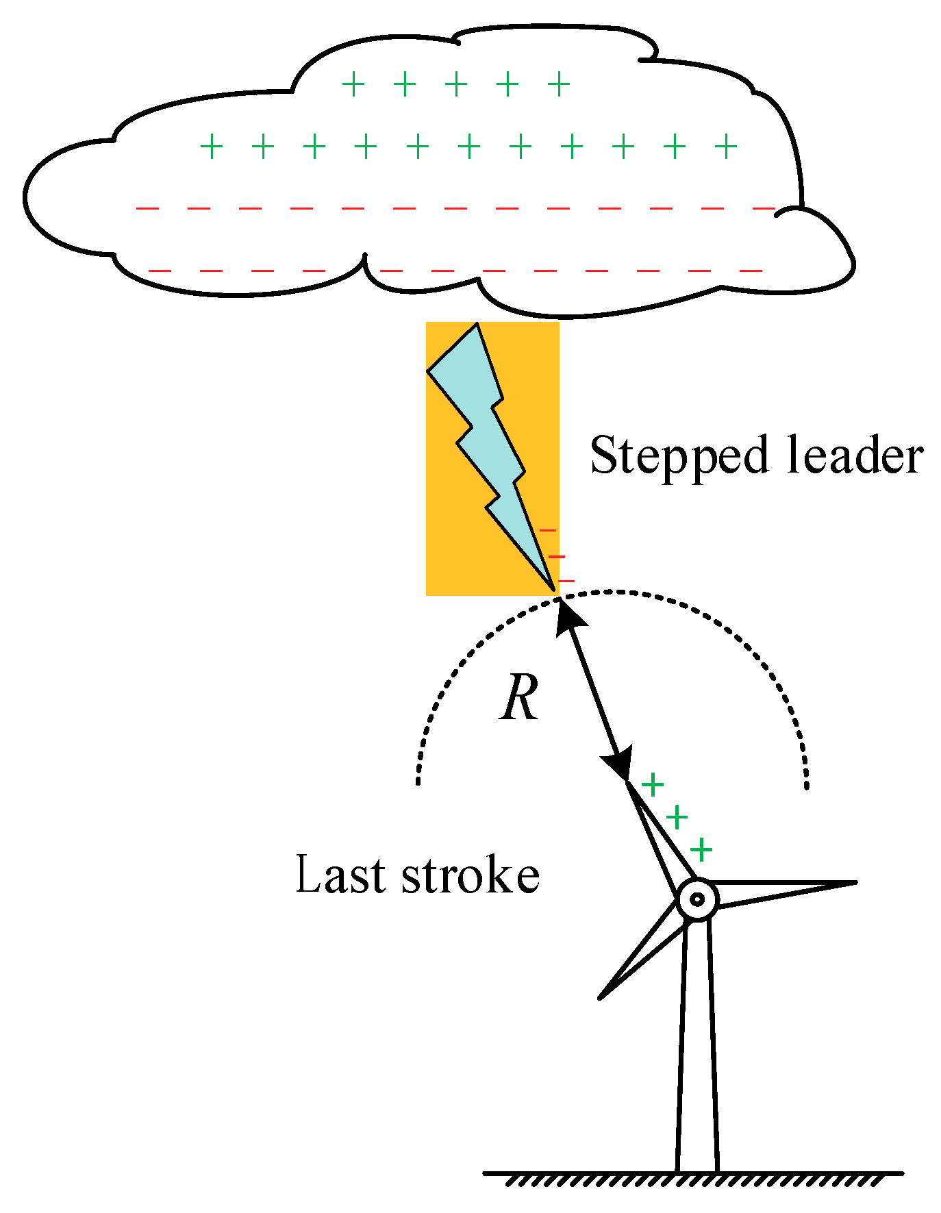
2.1. Lightning Leading Development Mechanism

Thunderstorm charges in thunderstorm clouds produce an average field strength of 2–3 kV/cm thunderstorm electric field in the atmosphere. When the electric field strength reaches an air breakdown strength of 25–30 kV/cm, the air is broken down and forms a stepped leader. The downward stepped leaders strike the wind turbine in two stages [23,24,25].
The first stage is the downward development process of a downward stepped leader. In this development process, the step length is approximately 50 m, the speed is 104 km/s, and the interval time between the steps ranges from 5 μs to 50 μs. However, the randomness of the downward development of lightning at this stage does not play a decisive role in the location of the lightning attachment point [26,27]. When the stepped leader reaches the top of the wind turbine, it enters the second stage.
The second stage is the “last stroke” process of lightning [28,29]. This process determines the final lightning attachment point. When the leader arrives at the second stage, the strong electric field around the wind turbine leads to a connection between the upward and downward leaders. At this time, the lightning stroke point of the wind turbine is determined. The blade is the most vulnerable to lightning strikes because it is the highest component of a wind turbine.
In Figure 1, for the wind turbine “last stroke” model, R represents the distance of the last stroke, which is determined by the lightning current amplitude.

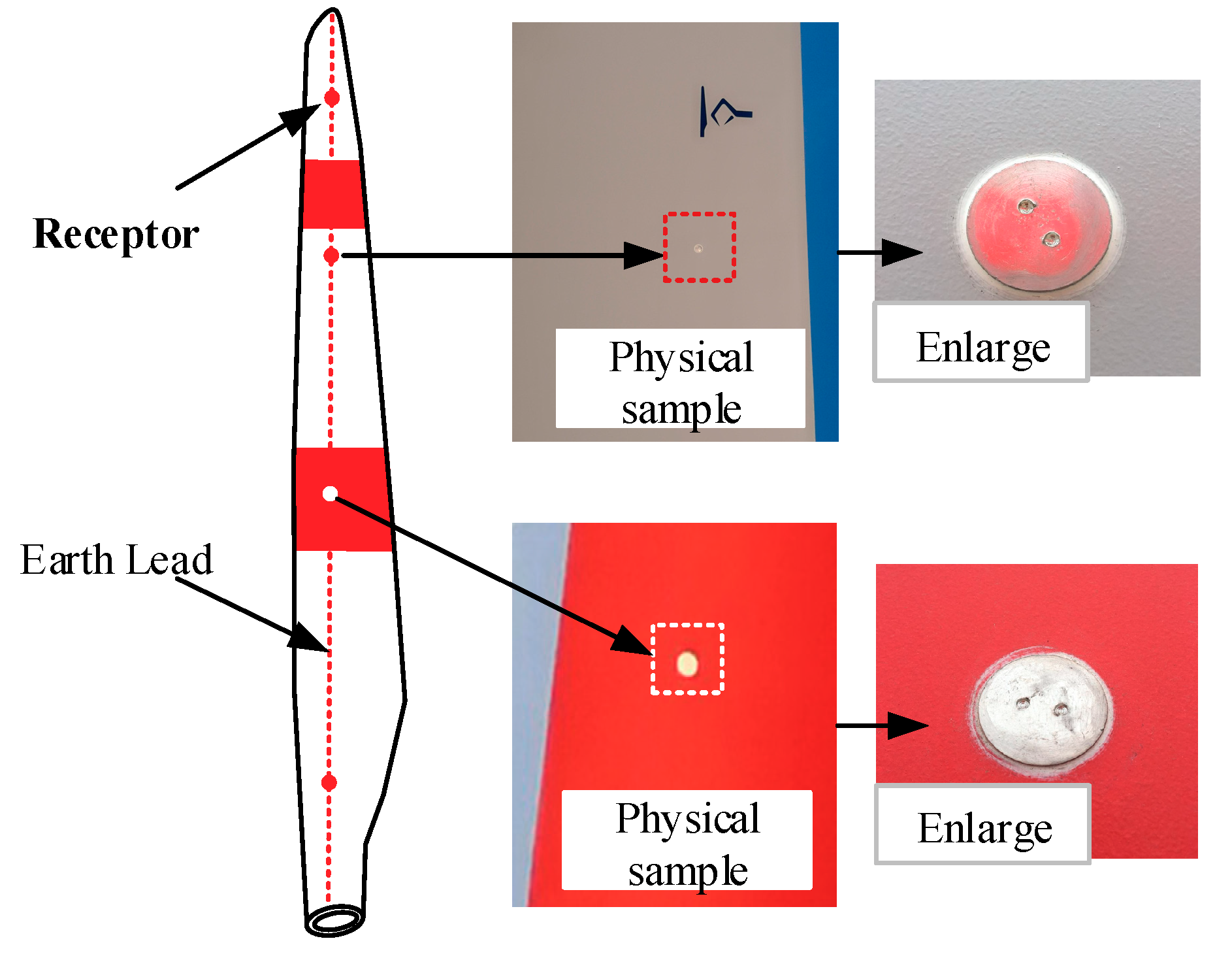
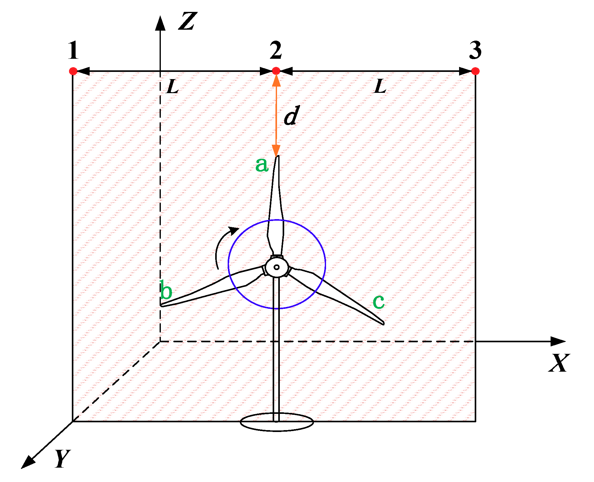
2.2. Design of Lightning Test Model for Wind Turbine

Figure 2a shows the rotating process of the wind turbine. The adjacent angles of the three blades are 120° and reset alternately at a 120° interval; thus, the angle of the wind turbine must be considered within 120° only. As shown in Figure 2b, the 120° angle is divided into four equal parts by 30° units. During the clockwise rotation from A-side to C-side, the contact height of the a-blade and b-blade changes in the reverse direction. When the A-side reaches the C-side position, the a-blade and b-blade are the same height, and their lightning effects tend to be the same in the model. During the C-side turning to E-side, the a-blade is gradually replaced by c-blade. Therefore, the a-blade was selected as the main analysis object, and the angle changes were mainly 0°, 30°, and 60°.
During preliminary research, the simulation and experiment were combined. In the simulation, the variable control method was used to calculate the average electric field intensity distribution of wind turbine blade when the lightning leader is in different positions during rotor rotation to three typical angles. Three different locations of lightning leaders are shown in Figure 3.
The scale model of a 2 MW wind turbine was built in the lightning stroke experiment at 1:100. Figure 4 displays the experimental circuit. The combined waveform (Umax = 2400 kV, 1.2/50 μs) was used as the simulated lightning impulse voltage source. Lightning experiments were conducted at the three different locations shown in Figure 3 by using rod discharge electrodes.
Figure 4 presents a diagram of the circuit and test module system in the experimental process. The high-definition fast recording device mainly recorded the attachment points in the instantaneous discharge process by using the exposure mode of a digital camera (exposure time: 10 s). The lightning receiving efficiency of blade receptors is denoted as Pr, and the overall lightning receiving efficiency of the blade is Pt. They describe the striking probability of the high-voltage pulse on the blade receptor and the striking probability of the entire blade (including the blade receptors), respectively. The formulas are as follows [1]:
P r = n a + n b + n c N ,
P t = n a + n b + n c + n o N .
In the formula, na, nb, and nc are the lightning attachment times of the three blade receptors in the scaled model. no is the number of lightning attachments on the blades, except the receptors, and N is the total number of tests.
Figure 5 shows the experimental results. During the change in rotation angle of the a-blade from 0° to 60°, the linear distance between the vertex of a-blade and the three lightning leader locations changed nonlinearly. These will lead to the change in electric field at the point of the a-blade. The electric field change of location 3 first rose and then fell, and the electric field changes of location 2 and location 1 generally presented downward trends of different rates. When the wind turbine blades are at different angles, the main attachment points are the blade receptors, with Pr ≥ 70% and Pt ≥ 80%. The receptor has a certain lightning protection function, but a considerable part of the lightning stroke process still exhibits “sideslip”, and reducing the probability of lightning “sideslip” under the existing conditions is highlighted. The lightning receptors installed in scale on the basis of the experimental model cannot satisfactorily represent the lightning attachment in a real situation because the single-value condition in the similarity criteria [30] of the wind turbine scale model is difficult to replicate and all similar parameters are not identical. For example, natural lightning stroke is often a multi-pulse process that depends on the reliability of the (MV level) high-voltage pulse source and scaled metal materials. In addition, the last stroke effect after the optimization of the blade receptor is difficult to reflect due to the influence of scaling. Therefore, the optimization and improvement of wind turbine blade receptors based on theory and simulation can effectively solve the problems.

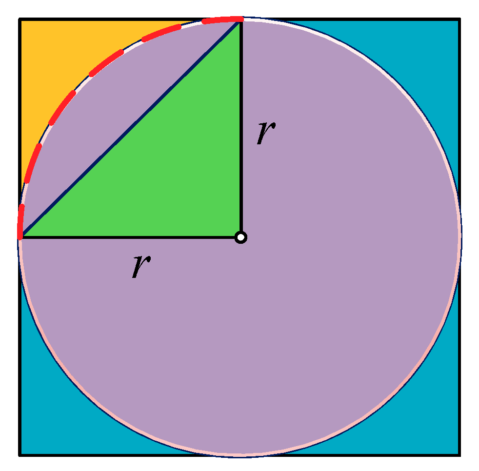
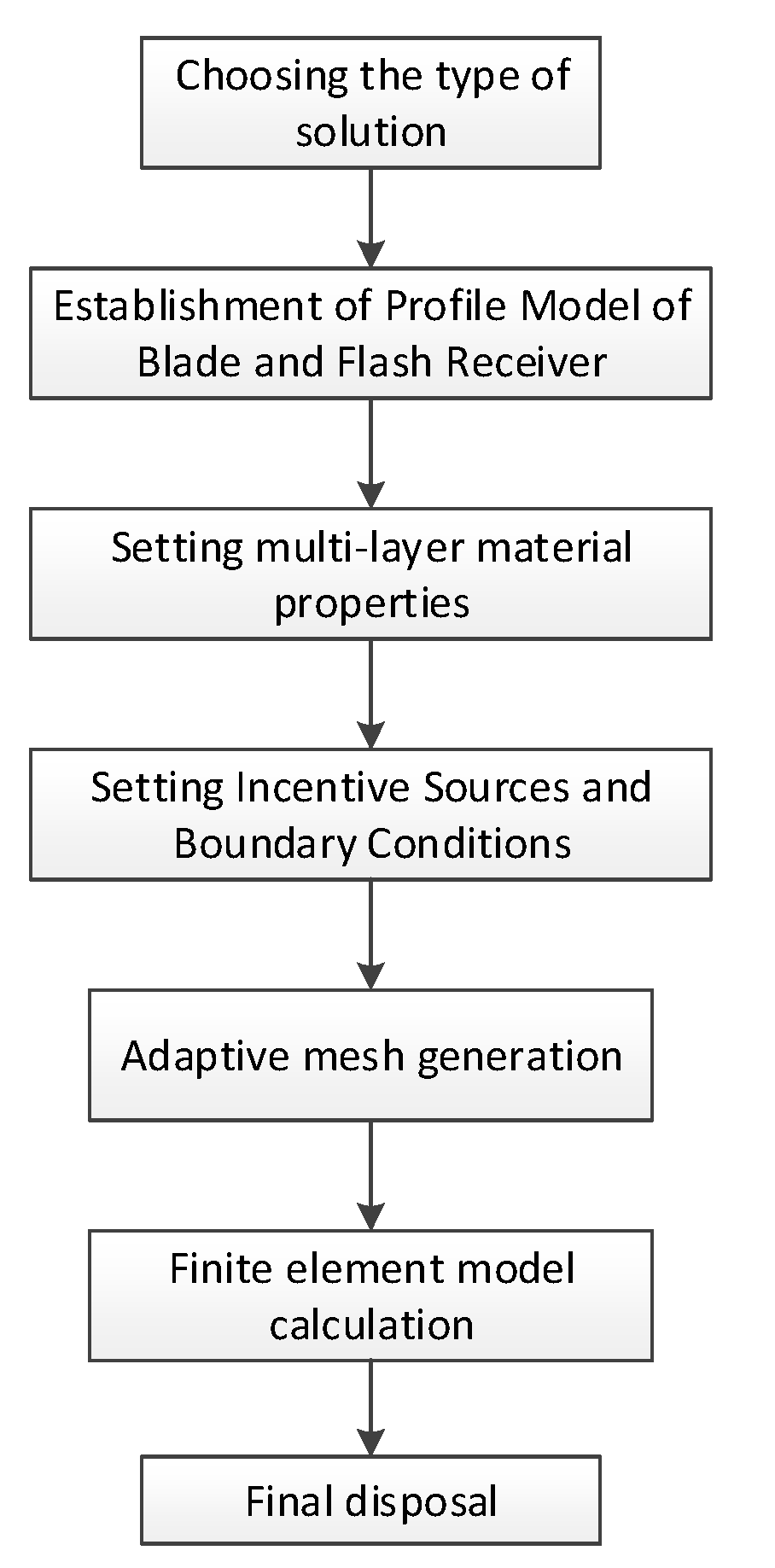
2.3. Solution of Electric Field Equation of Lightning Discharge

The development of the lightning stepped leader can be equivalent to a high-voltage electrode. On the basis of the Maxwell and Poisson equations and the boundary conditions, the distorted electric field around the blade can be solved [11,23]. Equation (3) is the differential form of the basic equation of electrostatic field:
{ × E = 0 D = ρ .
In the formula, E is the electric field intensity, V/m; D is the electric displacement vector, C/m2; and ρ is the charge density, C/m3. E can be expressed as follows:
E = φ .
In the formula, φ is the potential function of the electrostatic field, V.
In addition, the relationship between E and D is as follows:
D = ε E .
In the formula, ε is the dielectric constant.
The Poisson equation of the electrostatic field can be obtained by substituting Equations (5) and (4) into Equation (3):
2 φ = ρ / ε .
The COMSOL Multiphysics simulation software is based on the finite element method for solving electromagnetic field. On the basis of discrete mathematics, the finite element method divides the model into several sub-elements by applying meshing generation theory. The higher the number of sub-elements, the more accurate the results are. Then, the parameters of the sub-elements are solved. Finally, the results of all sub-elements are combined to obtain the parameters of the entire model. Figure 6 shows the flowchart of finite element software COMSOL.
The specific steps of the solution are as follows:
(1)
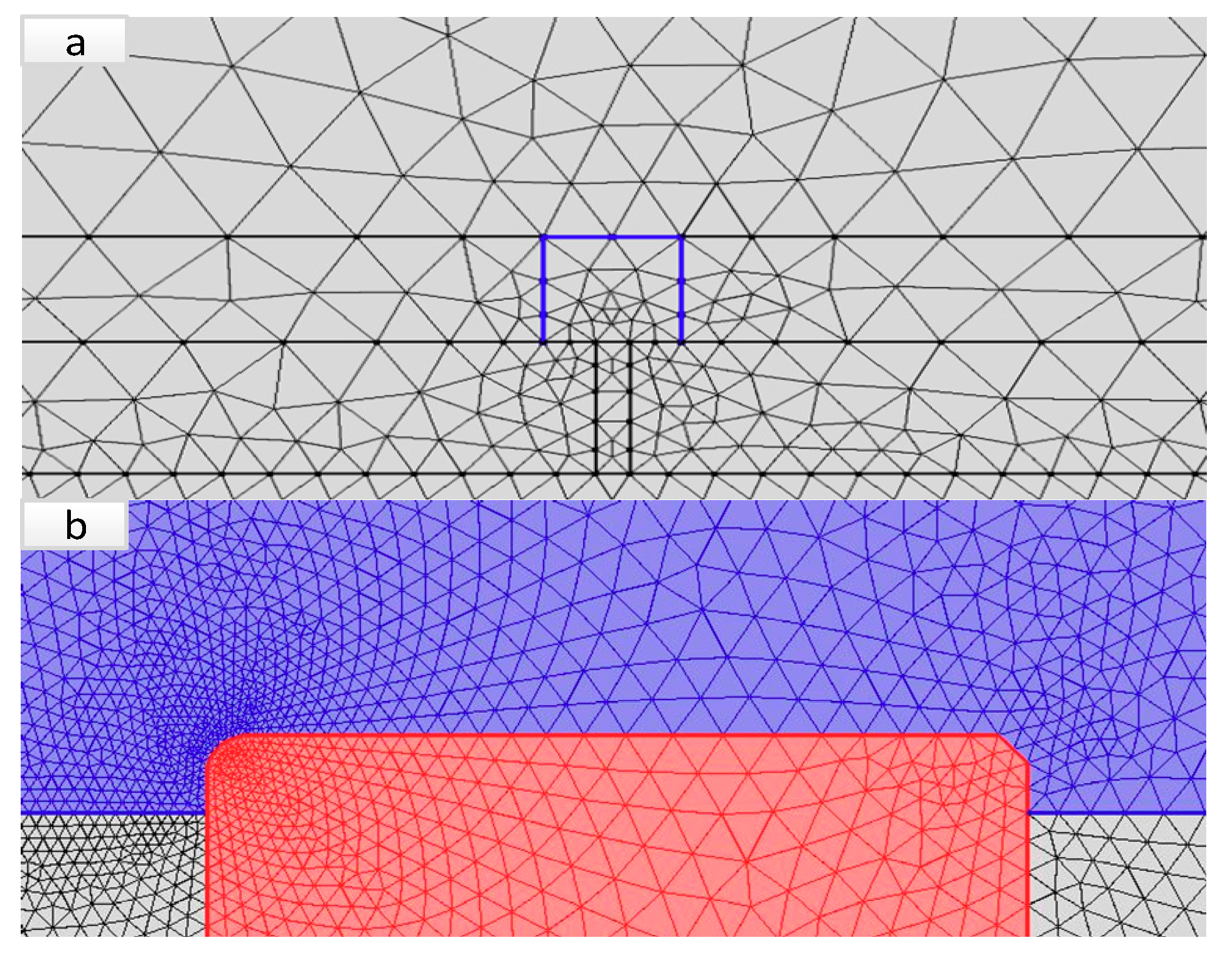
The calculation area is simplified, a reasonable solution area is selected, and the field is divided into several analytical units;
(2)
The electric field energy coefficient matrices of some elements are solved;
(3)
The total field energy coefficient matrices of some elements are solved;
(4)
The potential of each node is solved on the basis of the finite element equation, [K] [ φ ] = [B]-[P]. In the formula, [ φ ] is the inner node potential column vector, [K] is the coefficient matrix of order n × n, [B] is the column vector of free term, and [P] is the second boundary value column vector;
(5)
The other quantities of the electric field are calculated on the basis of the potential of each node.

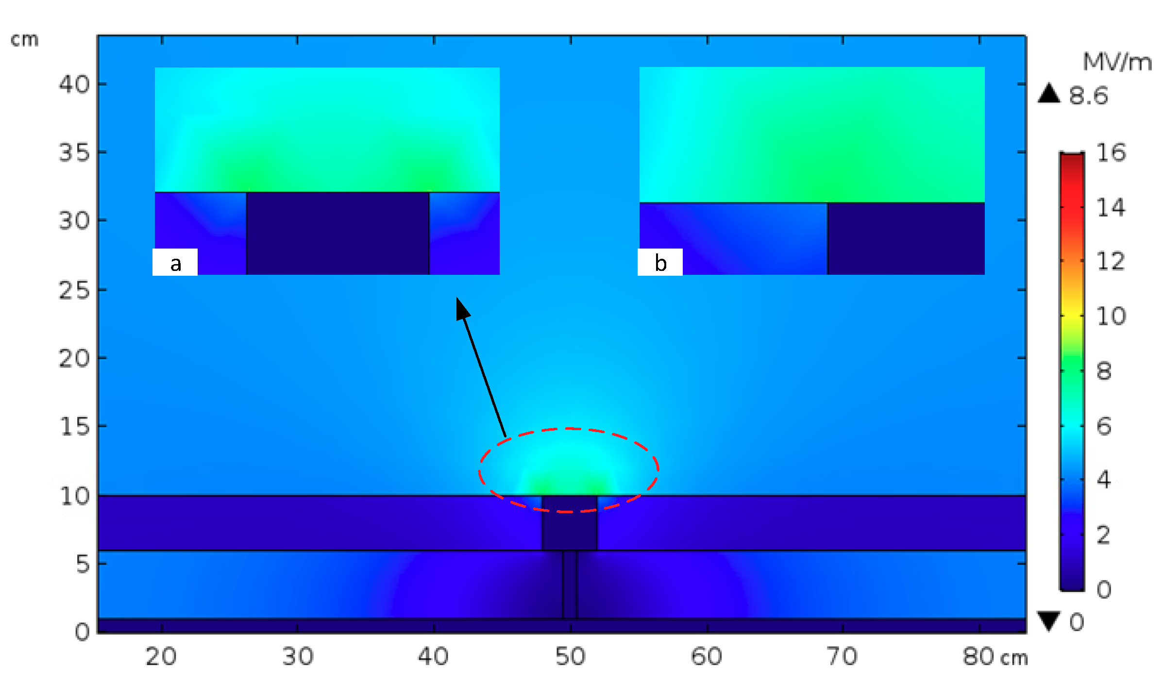
2.4. Establishment of Simulation Model for Blade Receptors

The outer layer of the blade around the receptors was a three-layer structure [24,25], which was made of fiberglass cloth inside and outside and polyvinyl chloride (PVC), polyethylene terephthalate (PET), or balsa wood in the middle. The raw material of the inner and outer fiberglass cloths was fiberglass, and its dielectric constant value was considerably greater than that of the middle layer of PVC/PET/balsa wood [31,32]. To compare the design differences of the different blade receptors, the outer layer of the blade was simplified as a single-layer fiberglass cloth structure. Figure 7 presents the simplified equivalent model of typical blade receptors.
Two types of blade products, namely, A-type and B-type, were selected as the basic modeling objects in this study. Their blade receptor diameters were 56 and 19 mm, respectively.
According to the literature [33], increasing the cross-sectional area of the receptor cannot substantially improve the interception effect of the lightning stroke. In accordance with the material and size requirements of the IEC 61400-24:2010 Standard Lightning Protection System [25], some basic parameters in this experiment were determined as follows: the diameter of the copper receptors was 40 mm, the dielectric constant of the glass fiber cloth was 4, the conductivity of copper was 5.8 × 10⁷ s/m, and the dielectric constant of background air was 1. The distance from the protruding blade surface of the receptor was 4 mm [11]. The triangular mesh fractal form was selected, and the adaptive fine mesh refinement was activated.
Primary mesh was performed on the solution domain, as shown in Figure 8a. The mesh around the blade receptors was further divided finely, as shown in Figure 8b, because the electric field distribution around the blade receptors required close observation.

3. Results and Discussion

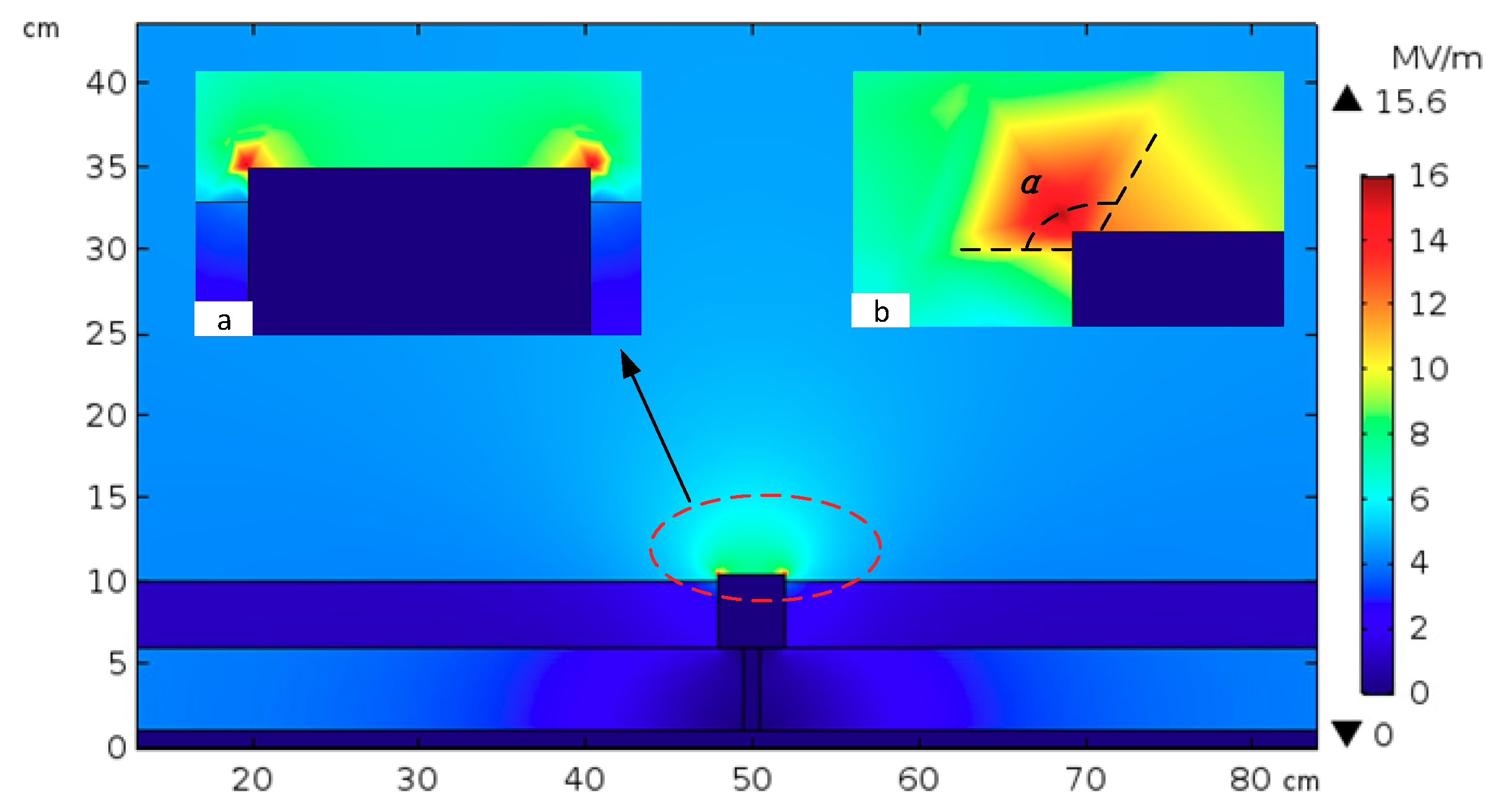
Analysis of Simulation Results

The A-type blade receptor was flat with a blade surface; it was tentatively designated as the flat right-angle receptor. The B-type blade receptor protruded by approximately 4 mm from the outer surface; it was tentatively designated as the convex right-angle receptor. To verify the difference between these types of blade receptors, the field distribution around them was solved via electromagnetic field simulation analysis.
Figure 9 shows the field intensity distribution of the (A-type blade) flat right-angle receptor. The electric field around the receptor was distorted to varying degrees after adding the receptor. The most serious distortion of the electric field was 8.6 MV/m, which appeared at the outer surface boundary of the receptor. During the lightning downward leader development, the upward leader is initially generated at the maximum field strength and connected to the downward leader of lightning to form the connection point. Therefore, the contact boundary between the blade and receptor will be damaged when the receptor boundary initially becomes the lightning connection point. In wind turbine accidents, the blade surface around the receptors often suffers lightning damage in a certain area.
Figure 10 shows the field intensity distribution of the (B-type blade) convex right-angle receptor. After the blade receptors protruded, the maximum field intensity remained around the contacting surface of the receptors with air. The maximum field strength reached 15.6 MV/m. Given the 4 mm projection relative to the blade surface, the highest point of the field intensity was projected, and the field intensity angle was greater than 90° after the first lightning stroke at the outer surface boundary of the blade.
A comparison of Figure 9 and Figure 10 shows that when the blade receptor was 4 mm higher than the blade surface under the same condition, the boundary field intensity of the external surface of the receptor changed significantly from 8.6 MV/m to 15.6 MV/m, exhibiting an increase of 81.40%. The results show that the electric field strength of the blade receptor increased significantly when the blade surface protruded, thereby enhancing the physical condition of the upward leader of the receptor.
The electric field intensity decreased exponentially at the edge around the blade receptor. In comparison with the (A-type) flat right-angle blade receptor, the (B-type) convex right-angle receptor could reduce the probability of damage caused by lightning to the blade surface to a certain extent. The analysis of the lightning stroke mechanism of blade receptors showed that with the increase in projection height of the receptor and blade surface on the outer surface, the concentration of induced charge ions increased at the moment of lightning stroke, which reduces the possibility of ion channel direction change from the pull of lightning leader due to the rotating blades. However, the blade receptor cannot indefinitely increase the protrusion height. Given that centrifugal force and wind resistance always exist in the blades of the wind turbines rotating under natural conditions, excessive protrusion will affect the aerodynamic function of the blades. Meanwhile, the protruding metal of the blade easily falls off or produces annoying noise [34,35].
In the case of limited receptor protrusion height, the receptor robustness against lightning in space must be ensured while reducing the probability of lightning damage to the wind turbines. In this study, the trapezoidal chamfering design of blade receptors was applied to optimize the shape of the (C-type) convex chamfer angle receptor. As shown in Figure 11, after the trapezoidal chamfering design, the maximum field strength was 14.3 MV/m under the same conditions. Although this value decreased by approximately 9% compared with the maximum field strength of the (B-type) convex right-angle receptor in Figure 10, the trapezoidal chamfering design of the blade flash connector could produce exactly two high field strength regions, namely, β1 and β2. Theoretical analysis showed that the development process of the front streamer before the formation of the connection leader is uncertain, and the lightning connection leader may be dragged by the blade. In this case, the high-value region of the multiple-field strength enhanced reliability for the formation of the lightning connection leader. That is, multiple centralized points are beneficial to the lightning protection of blades and can effectively reduce irreversible damage to the blade surface caused by lightning current dragging.
The chamfer structure was smoothed and optimized into fillet corners, as shown in Figure 12. The red dashed line part is the outer boundary of the convex fillet corner, and the blue solid line part is the outer boundary of the convex chamfered corner.
In the same environment, the minimum element value for constructing trihedral mesh via adaptive refinement and encryption is 0.002 cm. Figure 13 illustrates the electric field intensity. The simulation results showed that the maximum field intensity of the (D-type) convex fillet was 16.8 MV/m, and that of the (C-type) convex chamfer was 17.2 MV/m, with only a difference of 2.32%. However, the field intensity radius (Ra) of the (D-type) convex fillet was smaller than that (Rb) of the (C-type) convex chamfer, and the field intensity decreased substantially with the radius. Therefore, the (C-type) convex chamfering design has considerable advantages in theory. Figure 14 presents the (C-type) convex chamfering physical design.

4. Conclusions and Discussions

In this study, the experiment and simulation were conducted to systematically investigate and discuss the difference between the overall effect of blade lightning and the design of the protrusion height and type of the receptor. The field intensity distribution on the surface of a blade receptor is a high-boundary and low-middle structure that easily produces an upward connection leader at the edge. When the lightning struck the (A-type) flat right-angle receptor, the rotating blade “dragged” the lightning leader, which easily causes damage to the blade surface adjacent to the receptor. When the blade receptor protruded by 4 mm, it became a (B-type) convex receptor, and the distortion of the simulated electric field around it increased substantially. Under the same conditions, in comparison with the (A-type) flat right-angle receptor, the distortion electric field intensity of the (B-type) convex receptor increased by 81.40%, this is beneficial to improving the lightning receiving efficiency. Under the effects of wind noise, natural corrosion, and process reliability, the protrusion height of the receptor is limited. In the unilateral section structure, the (C-type) convex chamfer receptor had two evident electric field distortion points, compared with the (B-type) convex right-angle receptor, which had better reliability in terms of forming a lightning leader connection theoretically. Under the same conditions, the maximum electric field strength of the (D-type) convex fillet was similar to that of the (C-type) convex chamfer. However, the effective electric field radius of the (D-type) convex fillet was smaller and the attenuation of electric field intensity with radius was more evident than those of the (C-type) convex chamfer. Therefore, from a comprehensive point of view, the (C-type) convex chamfer receptor is more acceptable than the (D-type) convex fillet.
In addition, the height range of the blade receptor protruding, the reliability of the receptor in the natural environment, the damage assessment of the blade caused by the lightning stroke, the actual lightning receiving efficiency of the receptor after the high-voltage electrode is lower than the top of the blade, and how to observe the impact of lightning on the wind turbine synergistically with the actual multivariables, all need to be deeply considered and studied. In addition, theoretical simulation research plays an active role in understanding and optimizing the receptor of wind turbines, but data were not fully validated under actual conditions. Specifically, whether the scaled model can reflect the actual receptor effect after optimization must be verified, and subsequent optimization of the experimental conditions and in-depth research are still required.

Author Contributions

Data curation, H.C.; Investigation, P.L. and C.L; Methodology, D.L. and X.Y.; Writing—original draft, P.L. and C.L.

Funding

A Project Funded by the Priority Academic Program Development of Jiangsu Higher Education Institutions (PAPD) and the APC was funded by Heilongjiang Provincial Meteorological Bureau Innovation Team Fund, HQZD2018002 and supported by Heilongjiang Provincial Natural Science Foundation of China, LH2019E120.

Acknowledgments

The authors are thankful to the anonymous reviewers for their valuable comments.

Conflicts of Interest

The authors declare no conflict of interest.

References

  1. Wang, Y.; Wang, J.; Zhou, M.; Liu, Y.; Cai, L.; Xue, J. Lightning Attachment Characteristic of Wind Turbine Blade with Two-receptors. Proc. CSEE 2018, 38, 5307–5308. [Google Scholar]
  2. Hong, W.P.; Jin, M.L.; Niu, G.Q. Research on shell-side resistance characteristics of small-scale shell-and-tube heat exchangers. Chem. Mach. 2014, 41, 680–682. [Google Scholar]
  3. Birkl, J.; Diendorfer, G.; Thern, S.; Kolb, J.; Shulzhenko, E.; Rock, M. Initial investigation of influence of wind farms to lightning events. In Proceedings of the IEEE 33rd International Conference on Lightning Protection, Estoril, Portugal, 25–30 September 2016; pp. 25–30. [Google Scholar]
  4. Yokoyama, S.; Yasuda, Y.; Minowa, M.; Sekioka, S.; Yamamoto, K.; Honjo, N.; Sato, T. Clarification of the mechanism of wind turbine blade damage taking lightning characteristics into consideration and relevant research project. In Proceedings of the International Conference on Lightning Protection, ICLP, Vienna, Austria, 2–7 September 2012. [Google Scholar]
  5. Minowa, M.; Kunimatsu, T.; Yoda, M. Observation of lightning discharge to a wind power station at Hokuriku areas in 2013 winter season. In Proceedings of the Asia-Pacific International Conference on Lightning, APL, Nagoya, Japan, 23–27 June 2015; pp. 1–3. [Google Scholar]
  6. Garolera, A.C.; Madsen, S.F.; Nissim, M.; Myers, J.D.; Holboell, J. Lightning damage to wind turbine blades from wind farms in USA. IEEE Trans. Power Deliv. 2016, 31, 1043–1049. [Google Scholar] [CrossRef]
  7. Huang, J. The lightning system analysis and design of high-power wind turbine blades. Wind Power 2012, 5, 82–85. [Google Scholar]
  8. Xiang, X.; Xiaoqing, Z.; Cong, L. Simulation analysis on overvoltage in wind turbines by lightning stroke. Trans. China Electrotech. Soc. 2015, 30, 237–244. [Google Scholar]
  9. DNV. Design of Offshore Wind Turbine Structures; Offshore Standard (DNV-OS-J101); Det Norske Veritas: Oslo, Norway, 2007. [Google Scholar]
  10. Zhang, B.; Xue, H.; Zhang, B.; Zong, C.; Fan, Z. Influence of the wind vane tower barrel on the earthling connection’s impulse earthling characteristics in a lightning shock. High. Volt. Eng. 2012, 38, 2675–2682. [Google Scholar]
  11. Qibin, Z.; Canxiang, L.; Yu, C.; Xiaoyan, B.; Yang, Z. Shanghai Lightning Protection Center. Numerical simulation and protection of wind turbine blade lightning attachment zones. High Voltage Eng. 2017, 43, 2739–2745. [Google Scholar]
  12. Qu, L.; Wen, X.; Wang, Y.; SI, T.; Ma, Y.; Lan, L. Experimental study on the influence of the air terminal on triggered lightning ability of rotation wind turbine. High Voltage Eng. 2017, 43, 1628–1634. [Google Scholar]
  13. Fang, C.Y.; Li, J.T.; Zhang, Z.; Wen, X.; Wang, Y. Experimental study of the influence of the grounding resistance on triggered lightning abilities of wind turbine’s flabellum. Power Syst. Technol. 2015, 39, 1709–1713. [Google Scholar]
  14. Abd-Elhady, A.M.; Sabiha, N.A.; Izzularab, M.A. Experimental evaluation of air-termination systems for wind turbine blades. Electr. Power Syst. Res. 2014, 107, 133–143. [Google Scholar] [CrossRef]
  15. Ma, Y.; Zhang, L.; Yan, J.; Guo, Z.; Li, Q.; Fang, Z.; Siew, W.H. Inception mechanism of lightning upward leader from the wind turbine blade and a proposed critical length criterion. Proc. CSEE 2016, 36, 5975–5982. [Google Scholar]
  16. Holbøll, J.; Madsen, S.F.; Henriksen, M.; Bertelsen, K.; Erichsen, H.V. Discharge phenomena in the tip area of wind turbine blades and their dependency on material and environmental conditions. In Proceedings of the International Conference on Lightning Protection, ICLP, Kanazawa, Japan, 18–22 September 2006. [Google Scholar]
  17. Miki, M.; Miki, T.; Shindo, T.; Asuka, Y.; Honjo, N. Multi ground termination upward flash in winter lightning at the coastal area of the sea of Japan. In Proceedings of the International Conference on Lightning Protection, ICLP, Vienna, Austria, 2–7 September 2012. [Google Scholar]
  18. Cummins, K.L.; Qucik, M.G.; Rison, W.; Krehbiel, P.; Thomas, R.; Mcharg, G.; Engle, J.; Myers, J.; Nag, A.; Cramer, J.; et al. Overview of the Kansas Wind farm 2013 field program. In Proceedings of the International Conference on Atmospheric Electricity, Norman, OK, USA, 15–20 June 2014; pp. 1–16. [Google Scholar]
  19. Cotton, I.; Jenkins, N.; Pandiaraj, K. Lightning protection for wind turbine blades and bearings. Wind Energy 2001, 4, 23–37. [Google Scholar] [CrossRef]
  20. Lu, W.; Wang, D.; Zhang, Y.; Takagi, N. Two associated upward lightning flashes that produced opposite polarity electric field changes. Geophys. Res. Lett. 2009, 36, 277–291. [Google Scholar] [CrossRef]
  21. Honjo, N. Risk and its reduction measure for wind turbine against the winter lightning. In Proceedings of the Asia-Pacific International Conference on Lightning, APL, Nagoya, Japan, 23–27 June 2015. [Google Scholar]
  22. Garolera, A.C.; Cummins, K.L.; Madsen, S.F.; Holboell, J.; Myers, J.D. Multiple Lightning Discharges in Wind Turbines Associated With Nearby Cloud-to-Ground Lightning. IEEE Trans. Sustain. Energy 2015, 6, 526–533. [Google Scholar] [CrossRef]
  23. Ni, G. Principle of Engineering Electromagnetic Field; High Education Press: Beijing, China, 2009; pp. 103–107. [Google Scholar]
  24. Yasuda, Y.; Yokoyama, S.; Minowa, M.; Satoh, T. Classification of lightning damage to wind turbine blades. IEEJ Trans. Electr. Electron. Eng. 2012, 7, 559–566. [Google Scholar] [CrossRef]
  25. IEC. Wind Turbines, Part 24: Lightning Protection; IEC 61400-24:2010; IEC: Geneva, Switzerland, 2010. [Google Scholar]
  26. Zhao, Z. High Voltage Technique, 3rd ed; China Electric Power Press: Beijing, China, 2013; pp. 37–38. [Google Scholar]
  27. Hu, J.L.; Chuan, H.; Du, L. Simulation study on electric field of a long rod-plane air gap during leader discharge based on weak form of finite element method. Proc. CSEE 2008, 28, 148–154. [Google Scholar]
  28. Xie, S.; He, J.; Chen, W.; Chen, J.; He, H.; Gu, S.; Qian, G.; Xiang, N. Simulation study on the development process of the upward leader incepted from lightning rod. Proc. CSEE 2012, 32, 32–40. [Google Scholar]
  29. Chen, W.; He, H.; Qian, G.; Chen, J.; He, J.; Gu, S.; Xie, S.; Xiang, N. Review of the lightning shielding against direct lightning strokes based on laboratory long air gap discharges. Proc. CSEE 2012, 32, 1–12. [Google Scholar]
  30. Li, H. Study on the Similarity Criteria and Simulation Method of the Wind Tunnel Based Virtual Flight Testing; China Aerodynamics Research and Development Center: Mianyang, China, 2012; pp. 4–6. [Google Scholar]
  31. Madsen, S.F.; Holboell, J.; Henriksen, M.; Larsen, F.M.; Hansen, L.B.; Bertelsen, K. Breakdown tests of glass fibre reinforced polymers (GFRP) as part of improved lightning protection of wind turbine blades. In Proceedings of the Conference Record of the IEEE International Symposium on Electrical Insulation, Indianapolis, IN, USA, 19–22 September 2004. [Google Scholar]
  32. Dhanya, T.M.; Yerramalli, C.S. Lightning strike effect on carbon fiber reinforced composites—Effect of copper mesh protection. Mater. Today Commun. 2018, 16, 124–134. [Google Scholar] [CrossRef]
  33. Karegar, H.K.; Bagherian, H. Effects of Location, Size and Number of Wind Turbine Receptors on Blade Lightning Protection. Autom. Electr. Power Syst. 2012, 36, 122–127. [Google Scholar]
  34. Fisher, F.A.; Plumer, J.A.; Perala, R.A. Lightning Protection of Aircraft, 2nd ed.; Lightning Technologies Inc.: Pittsfield, MA, USA, 2004. [Google Scholar]
  35. Gewehr, H.W. Lightning Protection for Composite Rotor Blades. In Proceedings of the National Conference, Pittsburgh, PA, USA, 8–11 June 1980; American Wind Energy Association: Washington, DC, USA, 1980. [Google Scholar]
Figure 1. Last stroke of lightning.
Electronics 08 01418 g001
Figure 2. Diagram of the fixed rotation angle change of wind turbine blades. (a) The rotating process of the wind turbine. (b) The angle of the wind turbine within 120°.
Electronics 08 01418 g002
Figure 3. Schematic of the different positions of the blade at the fixed rotation angle with the lightning stroke leader.
Electronics 08 01418 g003
Figure 4. Systematic diagram of the lightning attachment test module system of blade.
Electronics 08 01418 g004
Figure 5. Diagram of the relationship between average electric field strength and lightning receiving efficiency between different blade rotation angle leaders and receptors.
Electronics 08 01418 g005
Figure 6. Solution process of finite element software COMSOL Multiphysics.
Electronics 08 01418 g006
Figure 7. Simplified equivalent model of blade lightning receiving and external structure of blades.
Electronics 08 01418 g007
Figure 8. Meshing graph for solving domain physical model. (a) Original grid of the lightning receptor. (b) Fine grid of the lightning receptor.
Electronics 08 01418 g008
Figure 9. Electric field distribution of the (A-type) flat right-angle receptor. (a), (b) Details of electric field at the boundary of the lightning receptor.
Electronics 08 01418 g009
Figure 10. Electric field intensity distribution of the (B-type) convex right-angle receptor. (a), (b) Details of electric field at the boundary of the (B-type) convex right-angle receptor.
Electronics 08 01418 g010
Figure 11. Electric field intensity distribution of the (C-type) convex chamfer angle receptor. (a), (b) Details of electric field at the boundary of the (C-type) convex chamfer angle receptor.
Electronics 08 01418 g011
Figure 12. Diagram of dimension design for convex chamfer and convex fillet.
Electronics 08 01418 g012
Figure 13. Contrast chart of electric field intensity distributions between the (C-type) convex chamfer receptor (b) and (D-type) convex fillet receptor (a).
Electronics 08 01418 g013
Figure 14. Typical sample diagram of the (C-type) convex chamfer blade receptors.
Electronics 08 01418 g014

