Article

Experimental Validation of a Reliable Palmprint Recognition System Based on 2D Ultrasound Images

School of Engineering, University of Basilicata, Viale dell’Ateneo Lucano 10, 85100 Potenza, Italy
*
Author to whom correspondence should be addressed.
Electronics 2019, 8(12), 1393; https://doi.org/10.3390/electronics8121393
Submission received: 30 September 2019 / Revised: 12 November 2019 / Accepted: 20 November 2019 / Published: 22 November 2019
(This article belongs to the Special Issue Recent Advances in Biometrics and its Applications)

Abstract

:
Ultrasound has been trialed in biometric recognition systems for many years, and at present different types of ultrasound fingerprint readers are being produced and integrated in portable devices. An important merit of the ultrasound is its ability to image the internal structure of the hand, which can guarantee improved recognition rates and resistance to spoofing attacks. In addition, ambient noise like changes of illumination, humidity, or temperature, as well as oil or ink stains on the skin do not affect the ultrasound image. In this work, a palmprint recognition system based on ultrasound images is proposed and experimentally validated. The system uses a gel pad to obtain acoustic coupling between the ultrasound probe and the user’s hand. The collected volumetric image is processed to extract 2D palmprints at various under-skin depths. Features are extracted from one of these 2D palmprints using a line-based procedure. Recognition performances of the proposed system were evaluated by performing both verification and identification experiments on a home-made database containing 281 samples collected from 32 different volunteers. An equal error rate of 0.38% and an identification rate of 100% were achieved. These results are very satisfactory, even if obtained with a relatively small database. A discussion on the causes of bad acquisitions is also presented, and a possible solution to further optimize the acquisition system is suggested.

1. Introduction

The use of biometric systems is continuously expanding in a wide variety of civilian applications where authentication based on behavioral or physiological characteristics is often replacing classical methods based on ID cards, passwords, or tokens. Several kinds of technology have been employed to collect various behavioral traits. The optical approach is generally relatively cheap thanks to the use of low-cost visible-band cameras, and can provide high-resolution images. It is the most exploited, as it allows the acquisition of several biometrics, including face, fingerprint, iris [1], and palmprint [2]. In some cases, the performance of biometric systems based on visible light is limited by variable illumination conditions and by their vulnerability to spoofing attacks. Recognition systems based on thermal infrared images of face or hand veins are often used as well as they assure liveness and are difficult to spoof because they contain under-skin information [3,4]; however, they may be influenced by ambient temperature. Capacitive sensors have been mainly tested for authentication based on fingerprint [5] and, more recently, there is a growing research interest in biometric systems based on photoacoustic sensors [6,7]. The recognition system described in the present work is based on ultrasound images.
The first research activities aiming to develop recognition systems that exploit ultrasound images of fingerprints date back to the end of the last century [8]. In the following years, several implementations of fingerprint ultrasound sensors have been experimented [9,10,11,12] and different types of ultrasonic fingerprint readers [13,14] are now produced and integrated in smartphone and tablet devices [15,16,17].
A main strength of the ultrasonic technique over other technologies is its capability to image internal portions of the human body, being able in this way to extract under-skin features that allow on one hand to improve recognition rates and on the other hand to detect liveness, which makes the biometric system resistant to spoofing attacks. As further merits, ambient noise (e.g., variations of illumination, humidity, or temperature) and oil or ink stains do not affect the ultrasound image. Several sensor technologies applications, including single piezoelectric elements, piezocomposite arrays, and more recently capacitive Micromachined Ultrasonic Transducers (cMUTs) and piezoelectric Micromachined Ultrasonic Transducers (pMUTs), as well as various techniques like pulse-echo, impediography, Doppler analysis, photoacoustics, and acoustic holography [18] have been tested to generate ultrasonic images for biometric recognition. Not only fingerprint, but also hand or finger geometry [19,20], vein pattern [21,22,23], and palmprint have been investigated.
Palmprint recognition based on 3D ultrasound has been systematically investigated in recent years by one of the authors. An automated system able to acquire 3D images of a region of the human hand was set up [24,25]. This system allows the obtainment of 3D information not only on the palm surface through curvature analysis methods [26] (which have been widely investigated for images acquired with optic techniques [2,27]), but also on the under-skin lines depth [28], which instead is a peculiarity of ultrasound. In order to provide a good propagation of the ultrasound wave, both the transducer and the hand were submerged in a water tank during acquisition. Even though this modality allowed to excellent recognition results to be obtained, such a wet system is not suitable for practical application because it is not acceptable to users.
To solve this issue, the system was modified by using a gel pad to provide an adequate acoustic coupling between the ultrasonic probe and the human hand [29]. A feature extraction procedure was subsequently proposed [30], and a preliminary evaluation was made by performing some verification experiments on a small database.
In the present work, the recognition procedure was optimized and validated through both verification and identification experiments carried out on a new and larger database than the one used in [30]. Additionally, an analysis of the main reasons for bad acquisitions is presented and possible solutions are suggested.
Section 2 presents basic concepts on ultrasound imaging and describes the acquisition system. Section 3 illustrates the proposed feature extraction procedure. The experimental results that validate the recognition systems are shown in Section 4, and the conclusions are reported in Section 5.

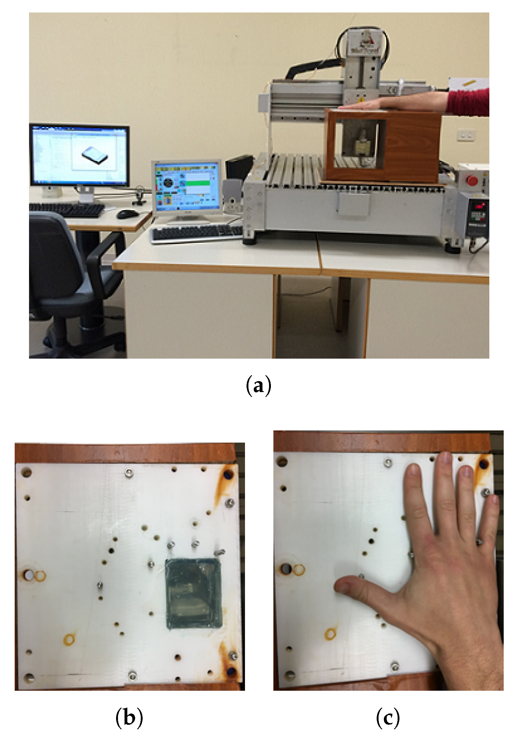
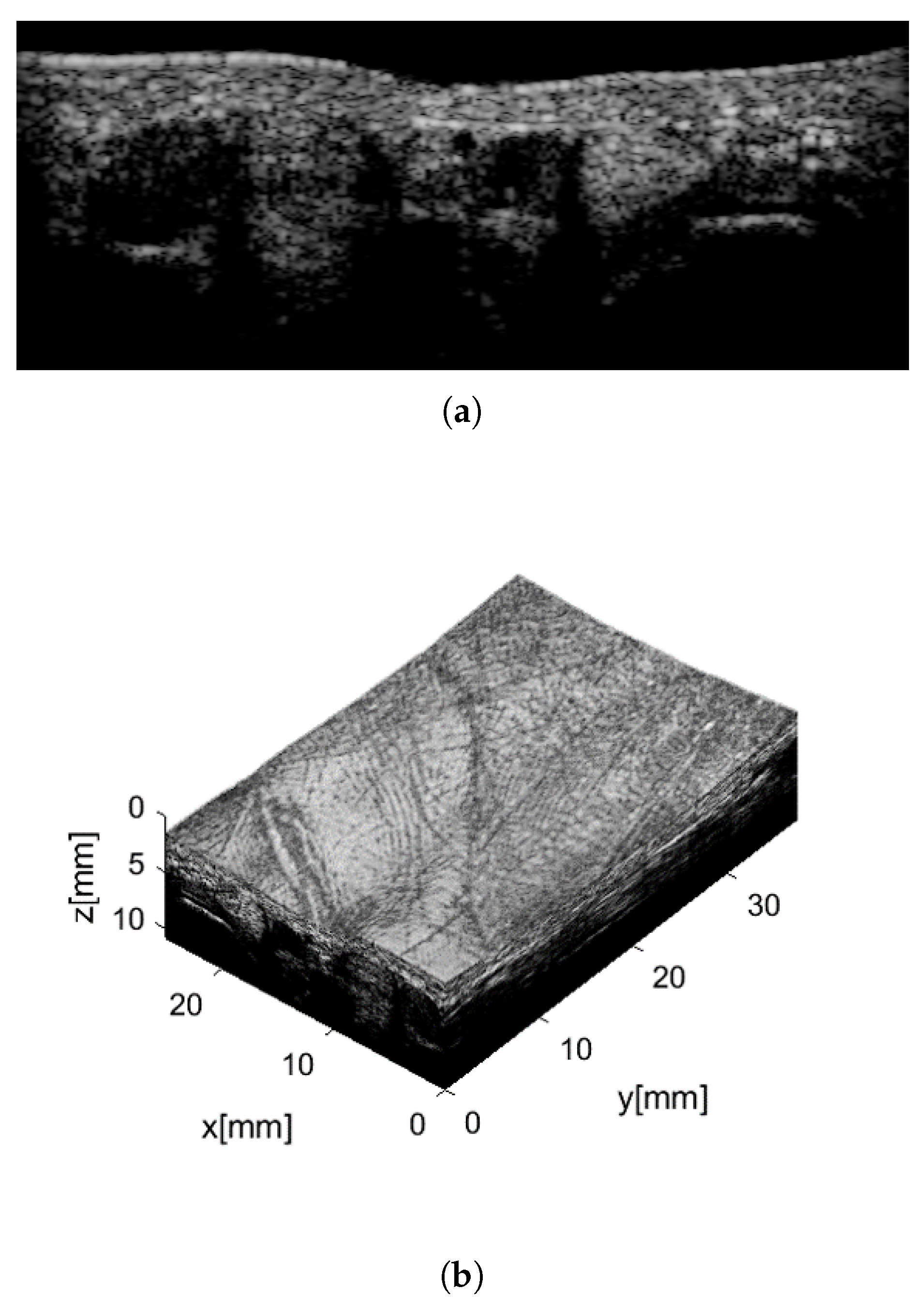
2. Ultrasound Imaging

The simplest way to generate an ultrasonic (or acoustic) 1D image is the amplitude mode (A-mode); it consists of transmitting a wave from a source and receiving reflected echoes after they have propagated in a medium. The distance between the source and each echo is related to the time of flight and to the wave velocity in the specific medium, while the amplitude of the received signal accounts for the reflectiveness of the target interface.
A two-dimensional image can be achieved by moving the source in one direction while several A-scans are performed. The acquired signals can then be processed to obtain a 2D grayscale image called brightness mode (B-mode), where the brightness of each pixel depends on the reflectivity of the corresponding point. However, a linear array of transducers allows a B-mode image to be obtained more quickly because of the electronic scan; also, with this modality, several beamforming techniques can be used (steering, focusing) in order to improve image quality.
The same reasoning holds for 3D ultrasound images; they can be collected by moving a single element transducer along two orthogonal directions, by moving a linear ultrasonic array along its elevation direction only, or by using a 2D array of transducers, which performs electronic scans along the two directions. This last approach would certainly be the most desirable, yet it involves difficult technological problems [31]. On the other hand, a single transducer may be used only when the scanning area is relatively narrow [11]. 3D ultrasound imaging is widely employed in medical diagnostic applications [32] in order to overcome the limitations of conventional 2D techniques in describing human anatomy.
The set up used to collect volumetric images of the human palm is shown in Figure 1 [24]. The ultrasound probe was a commercial linear array (LA435 by Esaote S.p.A., Italy) composed of 192 elements and realized with piezocomposite technology. It had a central frequency of about 12 MHz, a fractional bandwidth of about 75%, and a total aperture of 38.4 mm. The probe was driven by an ultrasound scanner specifically developed for research investigations [33] and was tied to a numerical pantograph with a precision of about 20 μ m. In previous works [24,25,26,28], good-quality 3D images of the human palm were achieved by submerging both the probe and the hand in a water tank. This solution allowed excellent recognition results to be obtained and hence demonstrated the possibility of using ultrasound images for palmprint recognition. On the other hand, this wet solution was quite uncomfortable and was rarely acceptable by users.
Another possibility is the use of a gel pad as coupling medium, as is common practice in medical diagnostics. To allow a comfortable positioning of the user’s hand, a rectangular window was made in a home-made hand-holder and filled with a 20-mm-thick layer of commercial medical gel pad (see Figure 1b). The user pressed their hand against the gel as the alignment was performed through a number of pegs, as shown in Figure 1c.
Note that the case was designed to contain the entire acquisition system, including the driving electronics and a stepper motor to perform the linear scan instead of the pantograph.
The procedure for acquiring a volumetric image was similar to that used in [24,25,26,28]. The probe scanned the palm region along the elevation direction and collected 250 B-mode images (like the one shown in Figure 2a), over a region of about 50 mm (i.e., with a step of 0.2 mm). The axial and lateral resolutions achieved were approximately 200 μ m and 350 μ m, respectively. These images were then grouped to form a 3D matrix of voxels and the acquired volume was cropped to about 25 × 38 × 11 mm 3 . An interpolation along the three directions was finally performed in order to provide a distance between two adjacent voxels equal to 46.2 μ m in any direction. In this way, the cropped volume was described with a 542 × 814 × 238 matrix of voxels, where the brightness of each voxel was represented in an 8-bit grayscale: dark and bright values corresponded to low and high wave reflection, respectively. Note that vein pulsing could be verified during the acquisition, which allows the liveness of the samples to be certified.
The 3D matrix was then processed to provide several renderings like the one shown in Figure 2b. The 3D image allows 3D information on palm curvature to be extracted, which could be used to extract 3D features as has been done with images collected with optical methods [2,27] and, more recently, also with images collected with the aforementioned wet system [26].
Furthermore, another kind of 3D palmprint information can be gained from this volumetric image—that is, the under-skin depth of principal lines and wrinkles, as was done in [28], again for the wet acquisition system. This task was performed by extracting the curved external surface of the palm and projecting it on a plane; in this way a 2D palmprint image was obtained. Then, a surface parallel to the first one but under the skin was extracted and projected on a plane as well, in order to achieve another 2D palmprint image. This operation was repeated several times by increasing the depth of the curved surface extraction until lines and wrinkles were no longer detectable.
A 2D feature extraction procedure was developed and applied to the 2D palmprint images collected at various depths. The obtained 2D templates were then combined to generate a 3D template, which provided a better recognition rate than any of those obtained using a 2D template. Note that acquisition techniques other than ultrasound are not able to extract this kind of 3D information.
Preliminary experiments demonstrated that palmprint images collected through the gel appeared quite different from those acquired through water [29] and, therefore, an ad hoc feature extraction procedure had to be derived. In the present work, a procedure for extracting features from a 2D palmprint at a single depth is presented and experimentally validated.

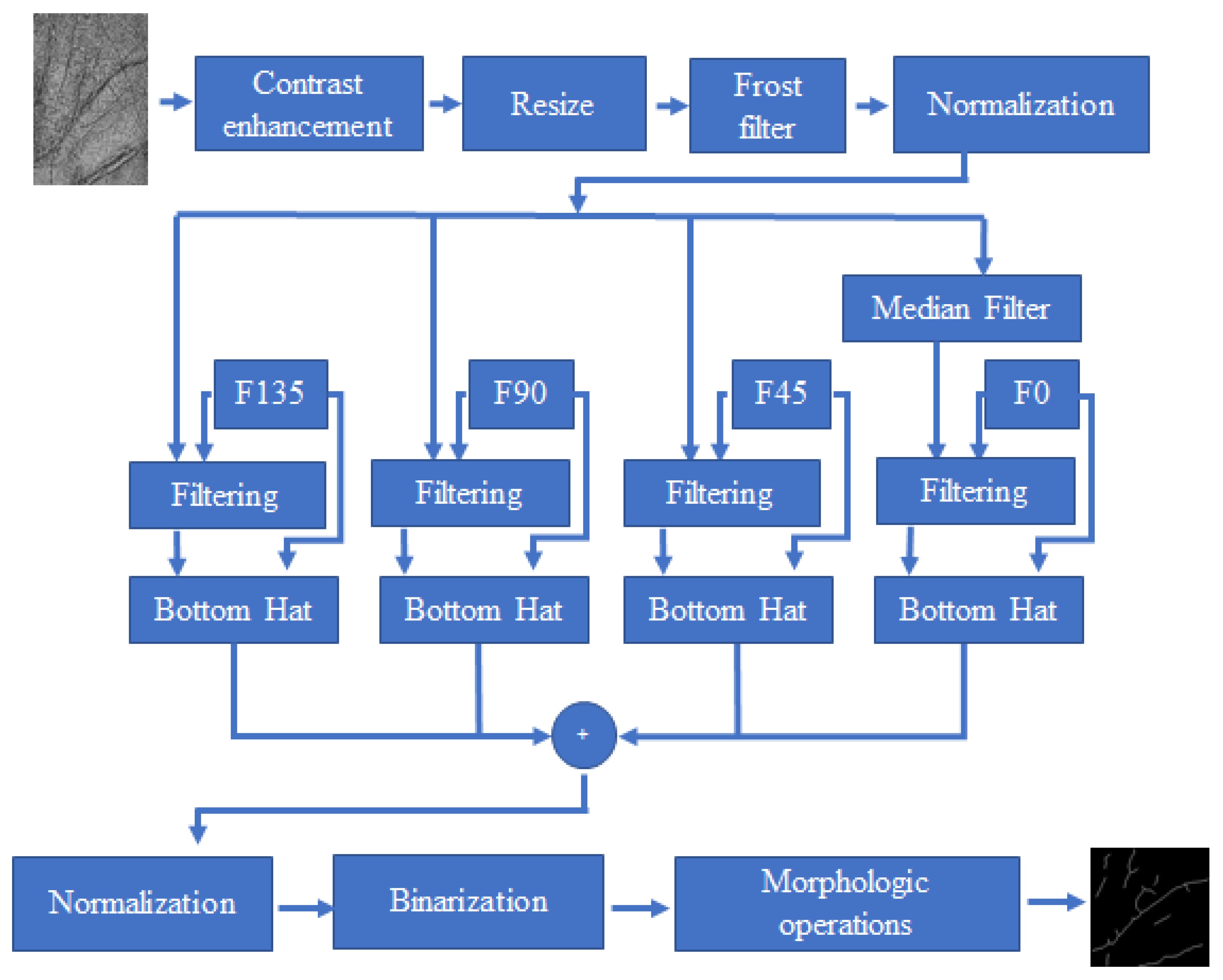
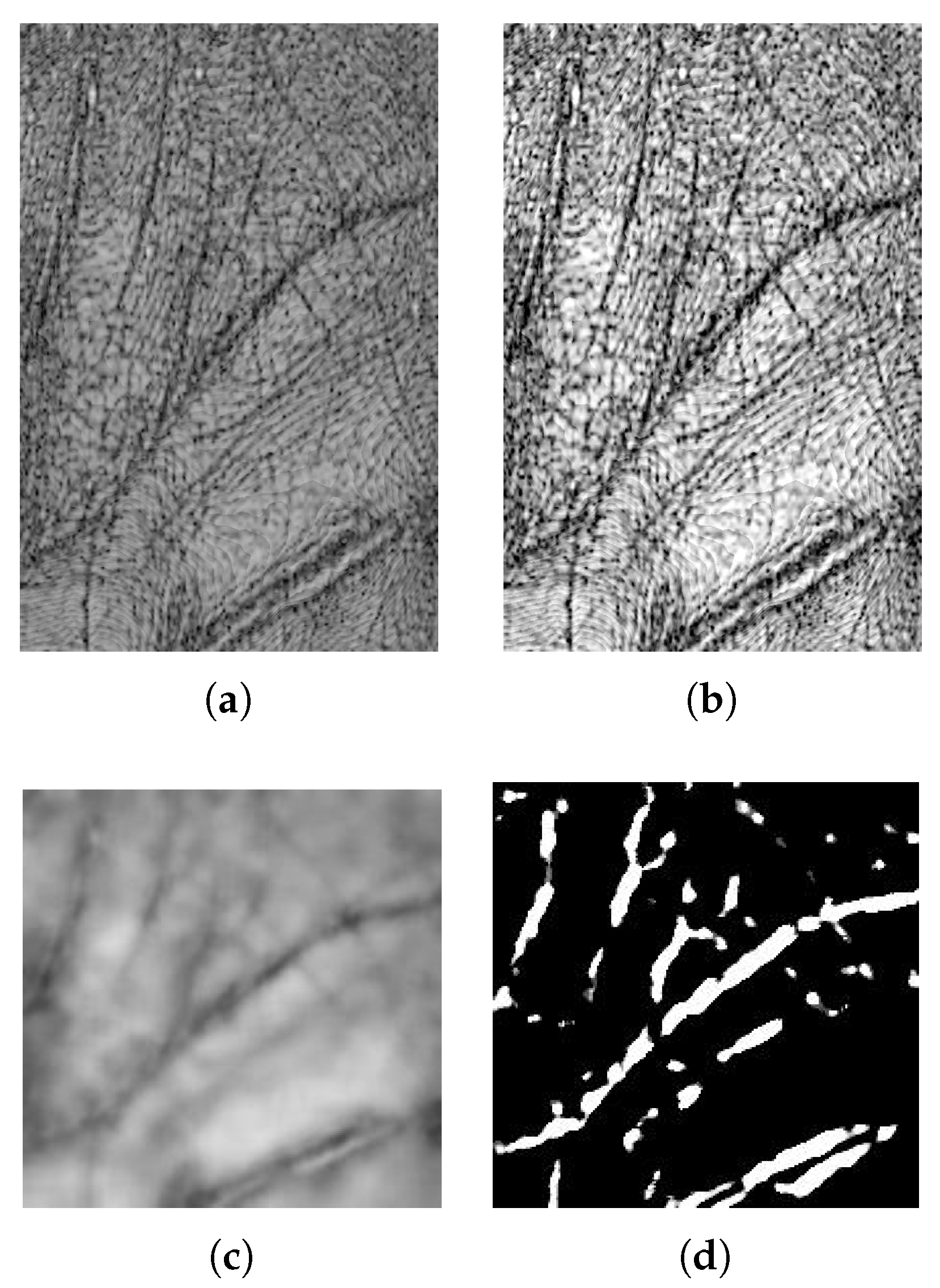
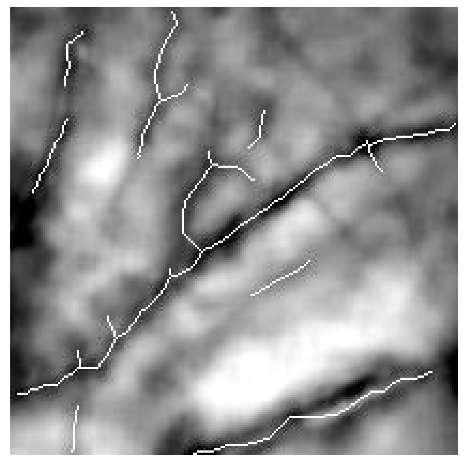
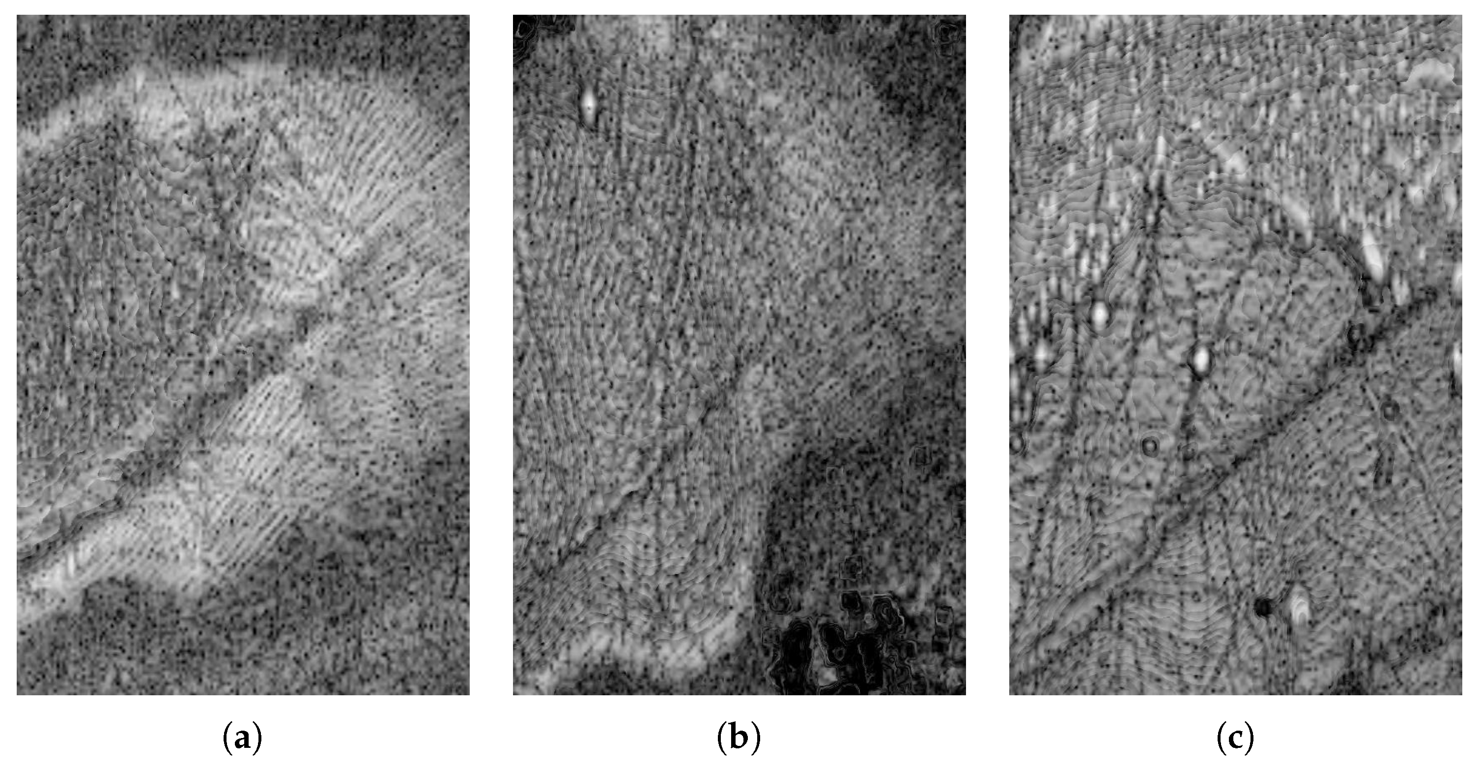
3. Features Extraction Procedure

Several approaches for palmprint feature extraction have been evaluated to date. Depending on the application, high-resolution (>500 dpi) or low-resolution (about 100 dpi) images were collected. High-resolution images are mainly used in law enforcement applications [34,35]; in this case, very similar to fingerprints, principal lines, wrinkles, ridges, valleys, and minutiae are extracted. Instead, low-resolution images have found wide use in many civilian applications [36,37], such as access control on a limited population base; here, features extraction is limited to principal lines and wrinkles only.
The main algorithms for feature extractions can be classified into five categories [36]: line-based [36,38], texture-based [37], appearance-based [39], multiple-features-based [40] and orientation-code-based [41] features. Various holistic techniques which learn the useful representations by applying statistical methods [42] have also been proposed.
A block diagram of the features extraction procedure is reported in Figure 3. The input is the 2D palmprint image shown in Figure 4a. It is a 8-bit grayscale image composed of 542 × 814 pixels. The image is extracted from the 3D matrix at an under-skin depth of 46.2 μ m, which is the distance between two pixels in the axial direction. The 2D image corresponding to the palm surface was not considered because it was very noisy. Main steps of the procedure are described in the following.
A contrast enhancement operation was first performed, providing the result shown in Figure 4b. Successively, the image was reshaped to a square image in order to perform the features extraction along four directions in a subsequent step. It was also scaled down to 128 × 128 pixels to reduce computational time for the following elaboration and for matching operations.
At this point, an adequate filter has to be chosen. A main problem in feature extraction with ultrasonic images is the inherent presence of speckle noise, which is a kind of multiplicative noise produced by the constructive and destructive interferences of backscattered echoes. It depends on several factors, including the kind of ultrasound probe, the working frequency, and the distance of the target, and it reduces the contrast and resolution of the image. Several algorithms have been proposed to decrease speckle noise [43]; among these, the Frost filter is one of the most used [44,45]. It is an adaptive spatial filter which substitutes a central pixel P ( x 0 , y 0 ) in a n x n moving kernel with the weighted sum of its surroundings. The weight W of each pixel depends on its distance from the central pixel:
W = α e α | t | ,
where α = σ 2 μ , σ 2 is the local variance, μ is the local mean, and | t | = | x x 0 | + | y y 0 | is the absolute distance of the pixel from P. Figure 4c shows the result.
Subsequently, after a normalization operation, the image was cloned in four copies and features were extracted by scanning each copy along four directions, that is, 0 , 45 , 90 , and 135 . This a common approach [46]. To only one of these images (i.e., the one scanned along the 0 direction), a median filter was first applied in order to reduce salt and pepper noise.
Feature extraction was then performed by a bottom-hat operation [47], which subtracted the input image from its closing in order to highlight image details. The images obtained from elaboration along the four directions were finally summed to produce the result shown in Figure 4d.
After another filtering stage, a further normalization operation was carried out to enhance the image contrast by stretching the range of intensity values. Hence, the image was binarized and subjected to some morphological operations. Figure 5 shows the achieved template superimposed to the image obtained after the application of the Frost filter (see Figure 4c).

4. Experimental Results

The recognition performances of the proposed system were evaluated by carrying out verification and identification experiments. Toward this end, new palmprint images were acquired by using different volunteers than those called in previous sessions [30], of both sexes and various ages. The established database consists of 281 3D images collected from 32 different users. Particular care was taken in guiding the users for a correct alignment of the hand, which resulted in a much lower percentage of bad acquisitions than those registered both in [30] and in [28]. However, some cases of noisy acquisitions were still recorded and, consequently, the corresponding images were discarded. Three kinds of corrupted images were identified. Figure 6 shows one example of each kind. In the image reported in Figure 6a, a wide and irregular bright region is present where lines and winkles cannot be detected. This problem was probably due to a non-perfect contact of the user’s hand with the gel pad. However, this situation only occurred in a couple of acquisitions. The second type of rejected image is shown in Figure 6b. In this case, there are dark regions in some places of the image that can be attributed to an incomplete outstretching of the hand. This behavior was encountered more often than the previous one, but still in limited cases. Finally, Figure 6c shows an image where many white speckles of different dimensions are found. These speckles are due to particles of dirt that were not cleaned after the previous acquisition, which acted as sound reflectors. There were only a few cases where such an amount of dirt was present, yet this problem occurred in several other collected images but in a lower amount (one or two spots), like in the image shown in Figure 6b. This last problem does not have an easy solution as long as a commercial gel pad is used, because it is somewhat flaccid and therefore is very difficult to clean quickly and adequately. This needs to be solved in order to provide improved reliability to the whole acquisition system. Toward this end, a new ergonomic pad that accounts for human hand convexity is under study. Instead of gel, it will be made of polydimethylsiloxane (PDMS), which is an organosilicon compound that has been successfully used in fingerprint acquisition systems [13].

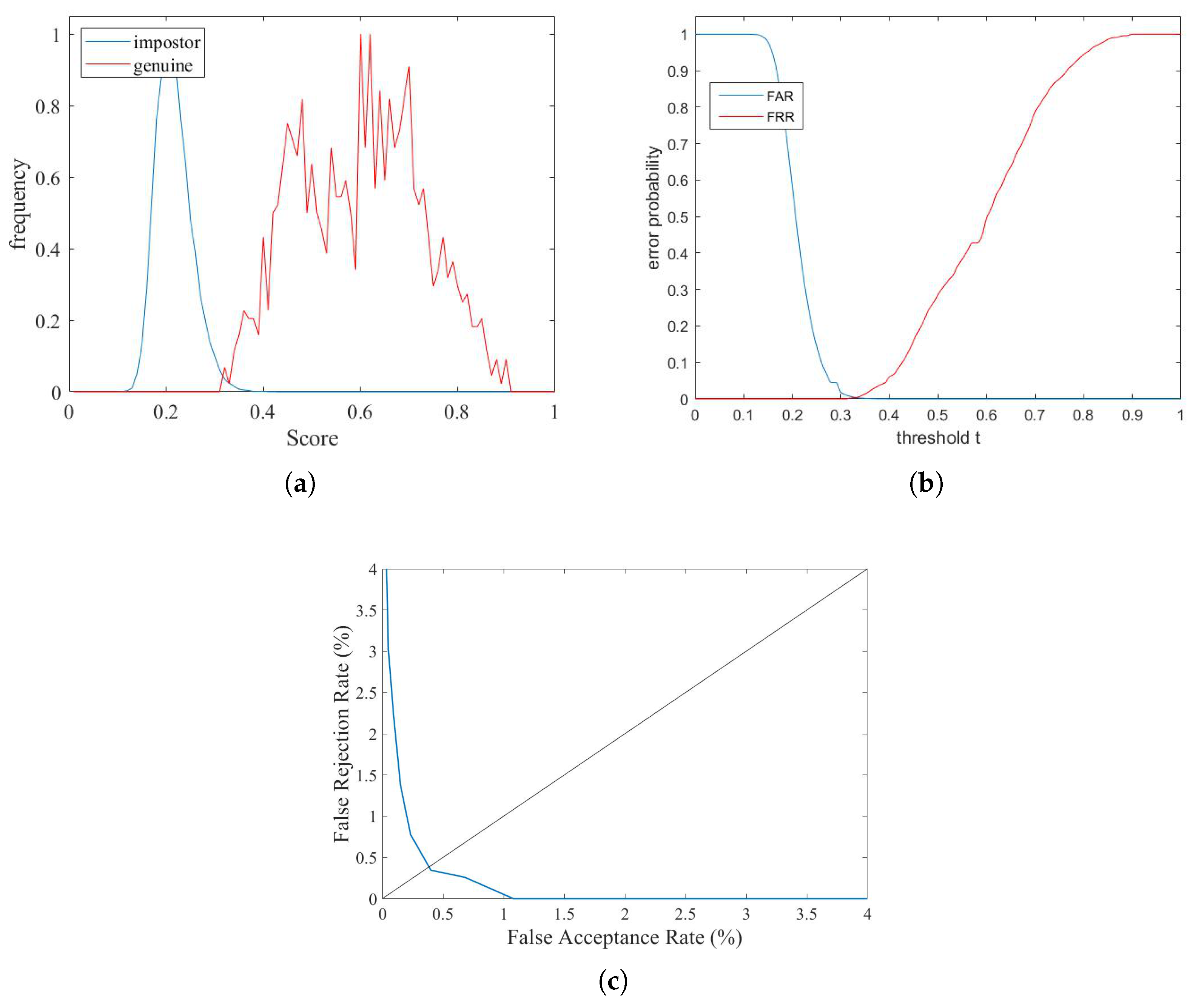
4.1. Verification Results

The verification/authentication modality consisted of a one-to-one comparison between a query template and the template corresponding to the claimed identity. Recognition performances of the proposed system in this modality were tested by performing comparisons between every possible pair of templates in the database. In this way, the statistical analysis is carried out on a higher number of matching scores than the reference-query approach, therefore providing a more reliable evaluation. A genuine score was obtained when two palmprints of the same subject were compared, while an impostor one was the result of a comparison between palmprints of different subjects. The verification experiments produced 1158 genuine and 38,182 impostor scores.
The matching score R C between two 2D binary images, representing the templates, was computed by performing the logical AND operation between corresponding pixels [2,48]:
R C = 2 n x n ( T R ( x , y ) > 0 ) ( T Q ( x , y ) > 0 ) n x n T R ( x , y ) + n x n T Q ( x , y ) ,
where T R is the reference template, T Q is the query template, and n × n is the dimension of the binary images. The resulting score is a value between 0 and 1, depending on the similarity of the two binary images. To account for small misalignments of the hand, various matchings were executed by performing small rotations and translations on one of the two templates; the best score was the registered one [2].
Recognition results are summarized in the plots shown in Figure 7a. The normalized distributions of impostor and genuine scores are shown in Figure 7b; it can be seen that there was a very small intersection region. A similar observation can be made by observing the plots of the false acceptance rates (FARs) and false rejection rates (FRRs) as a function of a threshold (Figure 7c). Finally, the detection error tradeoff (DET) curves, which plot FRR versus FAR for several thresholds, are shown in Figure 7c. The equal error rate (EER) is a parameter that is usually adopted to provide an immediate evaluation of the recognition performances of a biometric system. It is the error corresponding to the threshold value for which FAR = FRR. With the proposed system, the EER was equal to 0.38%. For comparison, verification results obtained with several methods can be found in [28,49].

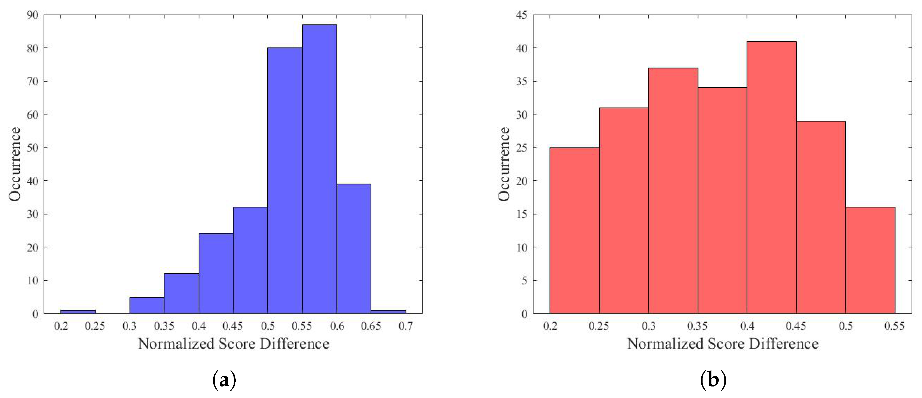
4.2. Identification Results

The identification modality consisted of comparing a query template against all templates. The system performed a one-to-many comparison against a biometric database in an attempt to establish the identity of an unknown individual. Similar to the verification tests, the experiments were carried out by comparing each template with all the other templates in the database. In this way, 281 tables each containing 280 scores were obtained. For each table, the scores were sorted in descending order and for all tables all genuine scores were higher than any impostor score, meaning an identification rate of 100%. It should be noted that this identification modality is more severe than the canonical one where a query template is compared with only one sample for each different subject.
In order to test the robustness of the system, the difference between the highest genuine score and the highest impostor score, normalized to the highest genuine score, was computed for all 281 tables and its distribution is shown in Figure 8a. The normalized differences between the lowest genuine and the highest impostor scores were also computed, and the distribution plot is shown in Figure 8b. As can be seen, in both cases, the normalized difference was at least higher than 0.2.

5. Conclusions

In this work, a palmprint recognition system based on ultrasound images was proposed and experimentally validated. The peculiarity of the system lies in the use of a commercial gel pad to provide an adequate acoustic coupling between the probe and the human hand, avoiding the need of the user to submerge their hand during the acquisition, which is uncomfortable and rarely acceptable. The probe mechanically scans the area of interest in order to collect a volumetric image, which is processed to extract 2D images of the palm at various under-skin depths. Features are extracted from one of these 2D palmprints using a line-based procedure. Verification and identification experiments were carried out to evaluate the recognition performances of the proposed system. Toward this end, a new database composed of 281 samples collected from 32 different users was established. Care was taken during each acquisition in order to minimize the number of bad acquisitions to be discarded; the possible causes of “noise” were evaluated and discussed. Additionally, a possible solution to improve the acquisition system was suggested. Experimental results produced an EER of 0.38% and an identification rate of 100%. Even if obtained with a relatively small database, these results are very satisfactory and encourage further optimization of the proposed system. A procedure to generate a 3D template by combining several 2D templates extracted with this procedure at various under-skin depths is currently under study. Additionally, more recent feature extraction techniques based on deep learning [50] or collaborative representation [51] are under investigation. Finally, the possibility of extracting other biometrics like vein pattern [22,23] and inner hand geometry [19] from the same acquired volume, implementing in this way a multimodal system, will be explored.

Author Contributions

A.I. conceived the methodology, supervised the experiments and wrote the paper, M.M. performed the simulations and analyzed the experimental data.

Funding

This research received no external funding.

Conflicts of Interest

The authors declare no conflicts of interest.

References

  1. Galbally, J.; Marcel, S.; Fierrez, J. Image quality assessment for fake biometric detection: Application to Iris, fingerprint, and face recognition. IEEE Trans. Image Process. 2014, 23, 710–724. [Google Scholar] [CrossRef]
  2. Zhang, D.; Lu, G.; Li, W.; Zhang, L.; Luo, N. Palmprint recognition using 3-D information. IEEE Trans. Syst. Man Cybern. Part C: Appl. Rev. 2009, 39, 505–519. [Google Scholar] [CrossRef]
  3. Soh, S.; Ibrahim, M.; Yakno, M. A review: Personal identification based on palm vein infrared pattern. J. Telecommun. Electron. Comput. Eng. 2018, 10, 175–180. [Google Scholar]
  4. Kakkirala, K.; Chalamala, S.; Jami, S. Thermal Infrared Face Recognition: A Review. In Proceedings of the 2017 UKSim-AMSS 19th International Conference on Computer Modelling & Simulation (UKSim), Cambridge, UK, 5–7 April 2017; pp. 55–60. [Google Scholar]
  5. Hierold, C.; Hribernig, G.; Scheiter, T. Biometric Capacitive CMOS Fingerprint Sensor Systems; Wiley-VCH: Weinheim, Germany, 2008; Volume 2, pp. 391–446. [Google Scholar]
  6. Choi, W.; Park, K. Fingerprint imaging of dry finger using photoacoustics. J. Acoust. Soc. Am. 2017, 141, EL205–EL209. [Google Scholar] [CrossRef]
  7. Wang, Y.; Li, Z.; Vu, T.; Nyayapathi, N.; Oh, K.; Xu, W.; Xia, J. A robust and secure palm vessel biometric sensing system based on photoacoustics. IEEE Sens. J. 2018, 18, 5993–6000. [Google Scholar] [CrossRef]
  8. Schneider, J.K.; Wobschall, D.C. Live scan fingerprint imagery using high resolution C-scan ultrasonography. In Proceedings of the 25th Annual 1991 IEEE International Carnahan Conference on Security Technology, Taipei, Taiwan, 1–3 October 1991; pp. 88–95. [Google Scholar]
  9. Bicz, W.; Banasiak, D.; Bruciak, P.; Gumienny, Z.; Gumuliński, S.; Kosz, D.; Krysiak, A.; Kuczyński, W.; Pluta, M.; Rabiej, G. Fingerprint structure imaging based on an ultrasound camera. Instrum. Sci. Technol. 1999, 27, 295–303. [Google Scholar] [CrossRef]
  10. Savoia, A.; Caliano, G.; Iula, A.; Longo, C.; Caronti, A.; Carotenuto, R.; Pappalardo, M. Design and fabrication of a cMUT probe for ultrasound imaging of fingerprints. In Proceedings of the IEEE Ultrasonics Symposium, San Diego, CA, USA, 11–14 October 2010; pp. 1877–1880. [Google Scholar]
  11. Maev, R.; Severin, F. High-speed biometrics ultrasonic system for 3D fingerprint imaging. In Proceedings of the SPIE—The International Society for Optical Engineering, Brussels, Belgium, 16–19 April 2012; Volume 8546. [Google Scholar]
  12. Lamberti, N.; Caliano, G.; Iula, A.; Savoia, A. A high frequency cMUT probe for ultrasound imaging of fingerprints. Sens. Actuators A: Phys. 2011, 172, 561–569. [Google Scholar] [CrossRef]
  13. Jiang, X.; Tang, H.Y.; Lu, Y.; Ng, E.J.; Tsai, J.M.; Boser, B.E.; Horsley, D.A. Ultrasonic fingerprint sensor with transmit beamforming based on a PMUT array bonded to CMOS circuitry. IEEE Trans. Ultrason. Ferroelectr. Freq. Control 2017, 64, 1401–1408. [Google Scholar] [CrossRef]
  14. Schmitt, R.; Zeichman, J.; Casanova, A.; Delong, D. Model based development of a commercial, acoustic fingerprint sensor. In Proceedings of the IEEE International Ultrasonics Symposium (IUS), Dresden, Germany, 7–10 October 2012; pp. 1075–1085. [Google Scholar]
  15. Sonavation, Inc. 2019. Available online: http://www.sonavation.com/ (accessed on 13 March 2019).
  16. Invensense, Inc. 2019. Available online: https://www.invensense.com (accessed on 13 March 2019).
  17. Qualcomm Technologies, Inc. 2019. Available online: https://www.qualcomm.com/solutions/mobile-computing/features/fingerprint-sensors (accessed on 13 March 2019).
  18. Iula, A. Ultrasound systems for biometric recognition. Sensors 2019, 19, 2317. [Google Scholar] [CrossRef]
  19. Iula, A.; De Santis, M. Experimental evaluation of an ultrasound technique for the biometric recognition of human hand anatomic elements. Ultrasonics 2011, 51, 683–688. [Google Scholar] [CrossRef]
  20. Narayanasamy, G.; Fowlkes, J.; Kripfgans, O.; Jacobson, J.; De Maeseneer, M.; Schmitt, R.; Carson, P. Ultrasound of the Fingers for Human Identification Using Biometrics. Ultrasound Med. Biol. 2008, 34, 392–399. [Google Scholar] [CrossRef] [PubMed]
  21. Zemp, R.; Bitton, R.; Li, M.L.; Shung, K.; Stoica, G.; Wang, L. Photoacoustic imaging of the microvasculature with a high-frequency ultrasound array transducer. J. Biomed. Opt. 2007, 12, 010501. [Google Scholar] [CrossRef] [PubMed]
  22. Iula, A.; Savoia, A.; Caliano, G. 3D Ultrasound palm vein pattern for biometric recognition. In Proceedings of the 2012 IEEE International Ultrasonics Symposium, Dresden, Germany, 7–10 October 2012; pp. 1–4. [Google Scholar]
  23. De Santis, M.; Agnelli, S.; Nardiello, D.; Iula, A. 3D Ultrasound Palm Vein recognition through the centroid method for biometric purposes. In Proceedings of the 2017 IEEE International Ultrasonics Symposium (IUS), Washington, DC, USA, 6–9 September 2017. [Google Scholar]
  24. Iula, A.; Hine, G.E.; Ramalli, A.; Guidi, F.; Boni, E.; Savoia, A.S.; Caliano, G. An enhanced ultrasound technique for 3D palmprint recognition. In Proceedings of the 2013 IEEE International Ultrasonics Symposium (IUS), Prague, Czech Republic, 21–25 July 2013; pp. 978–981. [Google Scholar]
  25. Iula, A.; Savoia, A.S.; Caliano, G. An ultrasound technique for 3D palmprint extraction. Sens. Actuators A: Phys. 2014, 212, 18–24. [Google Scholar] [CrossRef]
  26. Iula, A.; Nardiello, D. Three-dimensional ultrasound palmprint recognition using curvature methods. J. Electron. Imaging 2016, 25, 033009. [Google Scholar] [CrossRef]
  27. Bai, X.; Gao, N.; Zhang, Z.; Zhang, D. 3D palmprint identification combining blocked ST and PCA. Pattern Recognit. Lett. 2017, 100, 89–95. [Google Scholar] [CrossRef]
  28. Iula, A.; Nardiello, D. 3D Ultrasound Palmprint Recognition System Based on Principal Lines Extracted at Several under Skin Depths. IEEE Trans. Instrum. Meas. 2019. [Google Scholar] [CrossRef]
  29. Nardiello, D.; Calia, M.; Iula, A. An enhanced ultrasound technique for 3D palmprint recognition. In Proceedings of the 2016 IEEE International Ultrasonics Symposium (IUS), Tours, France, 18–21 September 2016. [Google Scholar]
  30. Iula, A.; Micucci, M. Palmprint recognition based on ultrasound imaging. In Proceedings of the 2019 42nd International Conference on Telecommunications and Signal Processing (TSP 2019), Budapest, Hungary, 1–3 July 2019; pp. 621–624. [Google Scholar]
  31. Han, J.; Gal, C.; Park, J.; Kim, J.; Lee, S.; Yeo, B.; Lee, B.; Park, S.; Park, S. Powder injection molding process for fabrication of piezoelectric 2D array ultrasound transducer. Smart Mater. Struct. 2018, 27, 075058. [Google Scholar] [CrossRef]
  32. Morgan, M.; Broder, J.; Dahl, J.; Herickhoff, C. Versatile Low-cost Volumetric 3D Ultrasound Platform for Existing Clinical 2D Systems. IEEE Trans. Med. Imaging 2018, 37, 2248–2256. [Google Scholar] [CrossRef]
  33. Tortoli, P.; Bassi, L.; Boni, E.; Dallai, A.; Guidi, F.; Ricci, S. ULA-OP: An advanced open platform for ultrasound research. IEEE Trans. Ultrason. Ferroelectr. Freq. Control 2009, 56, 2207–2216. [Google Scholar] [CrossRef]
  34. Dai, J.; Zhou, J. Multifeature-based high-resolution palmprint recognition. IEEE Trans. Pattern Anal. Mach. Intell. 2011, 33, 945–957. [Google Scholar]
  35. Cappelli, R.; Ferrara, M.; Maio, D. A fast and accurate palmprint recognition system based on minutiae. IEEE Trans. Syst. Man Cybern. Part B: Cybern. 2012, 42, 956–962. [Google Scholar] [CrossRef] [PubMed]
  36. Huang, D.S.; Jia, W.; Zhang, D. Palmprint verification based on principal lines. Pattern Recognit. 2008, 41, 1316–1328. [Google Scholar] [CrossRef]
  37. Zhang, L.; Li, H.; Niu, J. Fragile Bits in Palmprint Recognition. IEEE Signal Process. Lett. 2012, 19, 663–666. [Google Scholar] [CrossRef]
  38. Ali, M.; Yannawar, P.; Gaikwad, A. Study of edge detection methods based on palmprint lines. In Proceedings of the International Conference on Electrical, Electronics, and Optimization Techniques (ICEEOT 2016), Chennai, India, 3–5 March 2016; pp. 1344–1350. [Google Scholar] [CrossRef]
  39. Cui, J.; Wen, J.; Fan, Z. Appearance-based bidirectional representation for palmprint recognition. Multimed. Tools Appl. 2015, 74, 10989–11001. [Google Scholar] [CrossRef]
  40. Kumar, A.; Zhang, D. Personal authentication using multiple palmprint representation. Pattern Recognit. 2005, 10, 1695–1704. [Google Scholar] [CrossRef]
  41. Xu, Y.; Fei, L.; Wen, J.; Zhang, D. Discriminative and Robust Competitive Code for Palmprint Recognition. IEEE Trans. Syst. Man Cybern. Syst. 2018, 48, 232–241. [Google Scholar] [CrossRef]
  42. Rida, I.; Al Maadeed, N.; Al Maadeed, S. A Novel Efficient Classwise Sparse and Collaborative Representation for Holistic Palmprint Recognition. In Proceedings of the 2018 NASA/ESA Conference on Adaptive Hardware and Systems (AHS), Edinburgh, UK, 6–9 August 2018; pp. 156–161. [Google Scholar]
  43. Mansourpour, M.; Rajabi, M.; Blais, J. Effects and performance of speckle noise reduction filters on active radar and SAR images. In Proceedings of the 2006 ISPRS Ankara Workshop, Ankara, Turkey, 14–16 February 2006. [Google Scholar]
  44. Frost, V.; Stiles, J.; Shanmugan, K.; Holtzman, J. A Model for Radar Images and Its Application to Adaptive Digital Filtering of Multiplicative Noise. IEEE Trans. Pattern Anal. Mach. Intell. 1982, 4, 157–166. [Google Scholar] [CrossRef]
  45. Nardiello, D.; Iula, A. A new recognition procedure for palmprint features extraction from ultrasound images. Lect. Notes Electr. Eng. 2019, 512, 113–118. [Google Scholar]
  46. Bruno, A.; Carminetti, P.; Gentile, V.; La Cascia, M.; Mancino, E. Palmprint principal lines extraction. In Proceedings of the 2014 IEEE Workshop on Biometric Measurements and Systems for Security and Medical Applications, Rome, Italy, 17 October 2014; pp. 50–56. [Google Scholar]
  47. Gonzalez, R.C.; Woods, R.E. Digital Image Processing, 3rd ed.; Prentice-Hall, Inc.: Upper Saddle River, NJ, USA, 2006. [Google Scholar]
  48. Kim, M.K. Palmprint Recognition Based on Line and Slope Orientation Features. J. Inf. Sci. Eng. 2011, 27, 1219–1232. [Google Scholar]
  49. Genovese, A.; Piuri, V.; Plataniotis, K.; Scotti, F. PalmNet: Gabor-PCA convolutional networks for touchless palmprint recognition. IEEE Trans. Inf. Forensics Secur. 2019, 14, 3160–3174. [Google Scholar] [CrossRef]
  50. Bensid, K.; Samai, D.; Laallam, F.; Meraoumia, A. Deep learning feature extraction for multispectral palmprint identification. J. Electron. Imaging 2018, 27, 033018. [Google Scholar] [CrossRef]
  51. Guo, X.; Zhou, W.; Zhang, Y. Collaborative representation with HM-LBP features for palmprint recognition. Mach. Vis. Appl. 2017, 28, 283–291. [Google Scholar] [CrossRef]
Figure 1. Setup used for collecting 3D ultrasound images: (a) global view; (b) window filled with gel; (c) position of the hand.
Electronics 08 01393 g001
Figure 2. A collected ultrasound image: (a) an example of a 2D brightness mode (B-mode) image; (b) a 3D rendering of the palmprint.
Electronics 08 01393 g002
Figure 3. Block diagram of the extraction algorithm.
Electronics 08 01393 g003
Figure 4. Feature extraction procedure: (a) input 8 bit image (542 × 814 pixels); (b) image after contrast enhancement; (c) image after resize (128 × 128 pixels) and Frost filter; (d) image after bottom up and sum operations.
Electronics 08 01393 g004
Figure 5. The final template superimposed to the image obtained after the application of the Frost filter.
Electronics 08 01393 g005
Figure 6. Three kinds of corrupted images: (a) image with irregular bright regions due to imperfect contact of the user’s hand with the gel pad; (b) image with dark regions due to an incomplete outstretching of the hand; (c) image with several white speckles due to particles of dirt.
Electronics 08 01393 g006
Figure 7. Results of verification experiments: (a) normalized distributions of impostor and genuine scores; (b) false acceptance rates (FARs) and false rejection rates (FRRs) as a function of the threshold t; (c) detection error tradeoff (DET) curve. The equal error rate was 0.38%.
Electronics 08 01393 g007
Figure 8. Evaluation of the robustness of the identification results: (a) normalized difference between the highest genuine and the highest impostor scores; (b) normalized difference between the lowest genuine and the highest impostor scores. This value was always higher than 0.2.
Electronics 08 01393 g008

