1. Introduction
Visible light communication (VLC) with many attractive features has recently gained much attention because of the increasing demand for seamless mobile data connectivity [
1,
2]. To further improve the transmission rate of VLC systems, multiple input and multiple output (MIMO) has also been widely investigated and demonstrated to be a highly effective technique that can be employed in VLC systems [
3].
Meanwhile, light emitting diodes (LEDs) and photo detectors (PDs) are utilized as transmitters and receivers in general VLC systems, respectively. Multi-color red/green/blue (RGB) LED with better color rendering index and multi-channel parallel transmission can provide a higher transmission rate with a lower error rate in comparison with ordinary LED [
4]. Moreover, to improve the color qualities of white illumination light; quadrichromatic LED (QLED), usually with red/amber/green/blue (RAGB) colors, has been suggested as an alternative to RGB LED [
5]. Color shift keying (CSK) is a modulation method that exploits the diversity of a multi color LED to modulate the data with the intensity signals of different colors [
6]. The authors in [
7] recently proposed an enhanced CSK with QLED and considered various illumination qualities.
Moreover, the general communication through VLC channels mainly depends on the availability of line-of-sight (LOS) link. Various studies [
8,
9] have shown that the orientation and the mobility of the receiver are the two most important factors affecting the quality of the LOS link in VLC. The hemispheric receiver (HR) is one of the most representative angle diversity receivers (ADR) [
10] to achieve highly uncorrelated MIMO-VLC channels through altering the orientation angles of the PDs. Since the HR has a fixed value of the PDs orientation, it can not guarantee a good performance in all scenarios of receiver locations.
In this paper, we focus on designing the receivers of the MIMO-VLC systems that are composed of QLEDs. The optimization problem of maximizing the minimum Euclidean distance (ED) of the received signal that considers the normal vectors of the receivers under constraints is solved with the help of the Taylor expansion method. Moreover, a two-stage iterative algorithm is proposed to determine the optimal orientation with various initial input solutions. The simulation results demonstrate that the proposed method provides a better bit error rate (BER) performance in comparison with the conventional one, where the fixed orientation of the receiver is employed.
Notation: Throughout this paper, and denote an identity matrix and an matrix with all elements as one, respectively. Furthermore, denotes transpose, stands for the Frobenius norm. ⊗ and ∘ denote the Kronecker product and the element-wise product, respectively. The operator is a column vector resulting from stacking all the columns of .
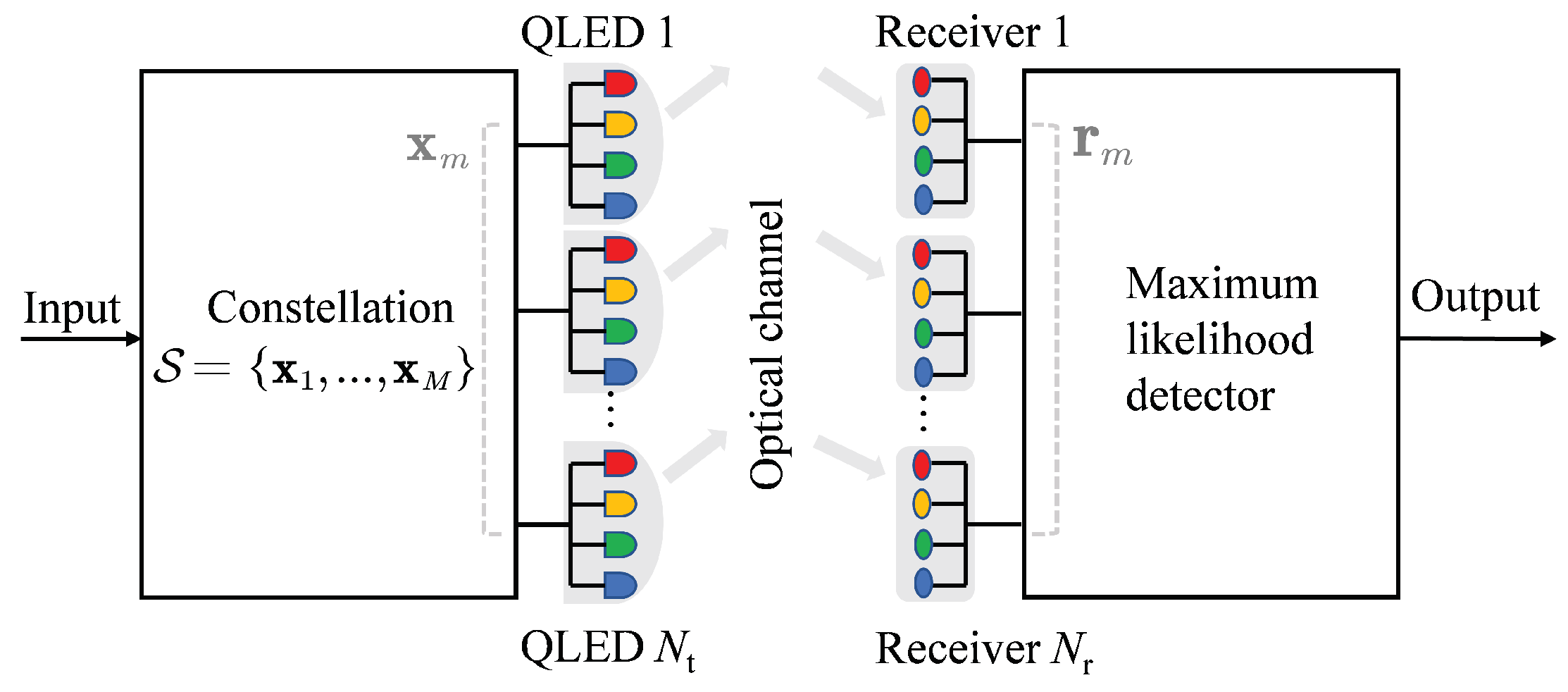
2. System Model
In this paper, a MIMO-VLC system with
QLEDs and
receivers (each receiver has four PDs and RAGB filters) are utilized to transmit data information as a
MIMO system shown with modulation order
M in
Figure 1. The transmitted symbol
is a vector of size
, where
. The constellation
where
M is the order of modulation with the transmission rate is
bps. Moreover, vector
can be expressed as
that denotes the mean current of the corresponding red, amber, green, and blue LED chips of all
RAGB-LEDs for the
m-th sending symbol. Moreover, the modulated signal vector of size
corresponding to each color is
, where
c denotes the LED color,
. In this paper, each QLED is assumed to employ the general CSK constellation that satisfies the maximum total power [
7]. The nonnegative signals also need to satisfy the maximum amplitude value constraint to avoid the clipping distortion and the chromaticity constraint [
5]. Moreover, since the design of the transmit signal is not our focus, some issues such as the nonlinear, flickering, or synchronization effect are assumed to be perfect [
5,
6,
7,
10].
Meanwhile, a data stream is mapped to a symbol vector chosen from the above constellation
. After transmitting through an optical channel, the received signal vector can be given by
where
is the noise vector with shot noise and thermal noise. The noise is assumed as the zero-mean additive white Gaussian (AWGN) noise with a covariance matrix
[
3].
denotes the channel matrix between the transmitters and the receivers with optical filters. We consider herein the crosstalk between adjacent colors and the
mutli-color channel matrix
in [
5] can be expressed by two matrices as
with
size matrices
, where
denotes the crosstalk interference ratio. Furthermore, the
submatrix
denotes the channel coefficients between the
QLEDs and
receivers, which can be written as
where
represents the gain factor between the
j-th QLED’s chip of the
c color and the
i-th receiver’s PD of
c color. For simplicity, since both QLEDs and multi-color receivers are assumed to be assembled in a compact package, and the distances between the transmitters and the multi-color receivers are much larger than either the physical size of the QLED clusters or the receiver clusters; hence, both could be viewed as points [
5] and [
7], respectively. Consequently, we can consider the same channel matrices
for
and omit the color notation
c for a simple representation.
Furthermore, the LOS link mainly contributes to the received power at the receiver side; therefore, as an initial exploration, we only consider the room with very low reflection coefficients. In other words, the received signal can be considered to contain only the LOS link for simplicity [
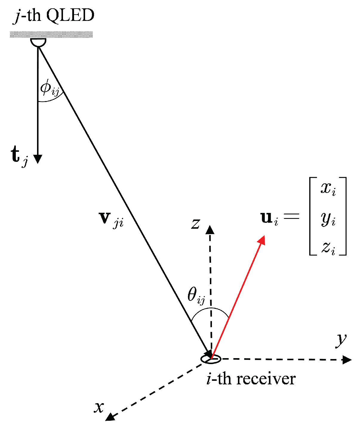
8]. Consequently, we have the following channel coefficient between each LED from the
j-th QLED and each PD from the
i-th receiver [
1]
where
is the angle of emergence with respect to the transmitter axis and
is the angle of incidence with respect to their normal axes, respectively.
,
, and
denote the effective area of the detector, the field-of-view (FOV) semiangle of the detector, and the responsivity of the receiver, respectively.
is the distance between the
j-th QLED and the
i-th receiver. The Lambertian mode order
is
, where
is the half power semiangle of the QLED. Moreover, at the receiver side, assuming perfect knowledge of the channel and ideal time synchronization, the maximum likelihood (ML) detector [
7] can be employed. More specifically, by minimizing the Euclidean distance between the received signal vector
and all possible received signals
as
, the receiver tries to decide which symbol
was transmitted.
4. Numerical Results
In this section, we give the results for the proposed and conventional receivers in the VLC system using QLEDs that are presented in a room measuring m. We consider a MIMO system as there are four RAGB LEDs and four multi-color receivers. The positions of QLEDs are fixed at m, m, m, m, respectively. Meanwhile, the receivers are located at two different sets of locations in two scenarios. In Location 1, the receivers are placed near the center as the coordinates are m, m, m, m. In Location 2, the receivers are positioned far from the center with the locations are m, m, m, m.
Moreover, each QLED employs the 4-CSK constellation [
7]. Consequently, there are 256 possible symbols for the system of four QLEDs. For simulation with transmission rate of
bps,
symbols are randomly chosen from the set of 256 possible symbols. Moreover, in this paper, we set
. The signal-to-noise ratio (SNR) is defined as
as transmit power is assumed to be normalized to unity [
3]. To find the set of optimal normal vectors for the receivers, the MATLAB optimization toolbox CVX is employed [
11]. A set of 200 initial normal vectors
is utilized to find the optimal orientation for the receivers. On the other hand, as mentioned in previous studies [
3,
5,
6,
7,
8,
9,
10], the conventional receiver generally employs
as the fixed normal vector since the receiver orientation is usually assumed to be orthogonal to the plane that contains the transmitters.
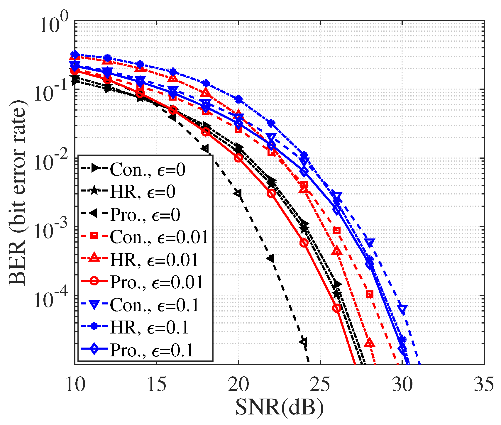
Figure 3 shows the performance comparison between the proposed, conventional, and the adapted HR [
10] for
bps in Location 1 with different crosstalk values. Moreover, the proposed receiver achieves different SNR gains for various
values. When
, the proposed receiver can achieve 3 dB SNR gain while the HR and conventional receiver have almost the same performances. In comparison with the conventional receiver, the proposed receiver can improve the performance by 4 dB in case of
while the gap is only 1 dB in case of
. Similarly, in comparison with the HR, the proposed receiver can achieve large SNR gains in the low and medium SNR regimes. The gaps are narrow in the high SNR regimes, but the proposed receiver still maintains better performance in comparison with the HR. Furthermore, the lower the crosstalk level, the better performances of all receivers. Meanwhile, the HR is a low complexity receiver that does not require the orientation adjustment when changing location but can not ensure a favorable and optimal performance in every location.
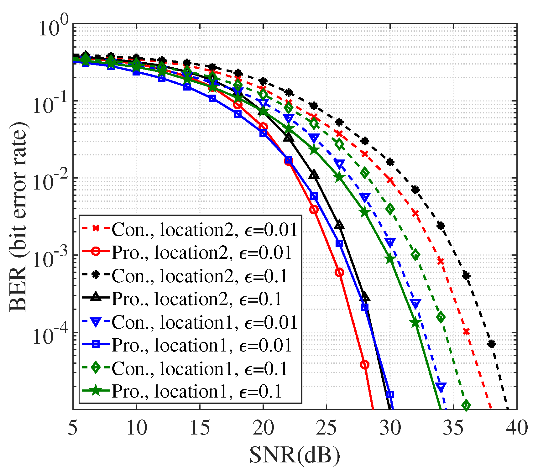
In
Figure 4, we compare the proposed and conventional receivers in both locations when
bps and
. Since Location 1 is near the center of the room, the correlation between the channel coefficients is high. Therefore, the performance of the conventional receiver in Location 1 is bad. The proposed receiver can significantly alleviate this problem by alternating the normal vectors with the SNR gains that are nearly 4 dB and 2 dB. In addition, in Location 2, the conventional receiver with straight upward normal vectors can not receive sufficient signal power from all QLEDs as in Location 1 and hence the performance becomes worst. However, the proposed receiver with an adequate tuning of the normal vectors can enhance the signal received from all QLEDs. This combines with the inherently low correlation of the MIMO channel in Location 2, dramatically improving the performance. In particular, the receivers in Location 2 have the best performance, and the SNR gains are around 9 dB for both cases of
.

