Review

Control Strategies for Floating Offshore Wind Turbine: Challenges and Trends

by
Tom Salic
1,
Jean Frédéric Charpentier
1,
Mohamed Benbouzid
2,3,* and
Marc Le Boulluec
4
1
Institut de Recherche de l’Ecole Navale (IRENav, EA 3436) French Naval Academy, 29400 Brest, France
2
Institut de Recherche Dupuy de Lôme (UMR CNRS 6027, IRDL), University of Brest, 29238 Brest, France
3
Logistics Engineering College, Shanghai Maritime University, Shanghai 201306, China
4
IFREMER Laboratoire Comportement des Structures en Mer BP 70, 29280 Plouzané, France
*
Author to whom correspondence should be addressed.
Electronics 2019, 8(10), 1185; https://doi.org/10.3390/electronics8101185
Submission received: 4 September 2019 / Revised: 9 October 2019 / Accepted: 11 October 2019 / Published: 18 October 2019
(This article belongs to the Section Systems & Control Engineering)

Abstract

:
The offshore wind resource has huge energy potential. However, wind turbine floating structures have to withstand harsh conditions. Strong wind and wave effects combine to generate vibrations, fatigue, and heavy loads on the structure and other elements of the wind turbine. These structural problems increase maintenance requirements and risk of failure, while reducing availability and energy production. Another challenge for wind energy is to reduce production costs in order to be competitive with other alternatives. From the control point of view, the objective of lowering costs can be achieved by operating the turbine close to its optimum point of operation under partial load, guaranteeing reliability by reducing structural loads and regulating the power generated in strong wind regimes. In this typical and challenging context, this paper proposes a critical state-of-the-art review, discussing challenges and trends on floating offshore wind turbines control.

1. Introduction

Wind energy has been growing exponentially for 20 years in the energy industry. Since the beginning of the 21st century, the total wind turbine (WT) power installed in the world amounts to 591 GW according to the Global Wind Energy Council (GWEC) report [1]. Even though the majority of the installations remain terrestrial wind turbines, the offshore turbine market has been growing strongly for 10 years with 23 GW connected [1].
Installed offshore wind turbine (OWT) remains a reliable solution but requires depths below 60 m [2]. The distance from the coasts can offer several advantages: more important wind resource, ability to exploit large area of uninterrupted open sea and a reduced visual and noise impact. The North Sea with its shallow depths is a privileged place for this type of installations [3]. A limited number of sites is therefore available for countries involved in offshore wind. The floating offshore wind turbine (FOWT) offers a solution for deeper water OWT setup. Inspired by the oil and gas industry, there are several platform configurations for floating offshore wind turbines. The three main submersible concepts are: the barge, the spar and the tension leg platform (TLP) (see Figure 1) [4]. The first category deals with large flotation systems (barge), which ensures good stability. For the second category, the stability is reinforced by ballast in the lower part of the floating platform in order to lower the center of gravity of the system. This is the case of spar, cylindrical vertical platforms with large draft. The stability of the third category systems is insured by the tension in the mooring lines (the case of Tension Leg Platforms (TLP), which are platforms anchored to the seabed by vertical mooring lines). In this case, the high stiffness value of the mooring lines ensures stability. The possibility of mixing these different concepts in order to optimize the dynamic behavior of the platforms is conceivable [5]. This is the case of semi-submersible foundation; it is actually a merger of the concepts of spar and barge type. The main challenges are to combine stability, acceptable motions and low costs. However, waves, currents, and strong winds cause relative movements on the platform. These displacements reduce the performance of the turbines and generate aging of the structures. The damage fatigue leads to additional operating costs caused by structure failure. According to the International Electrotechnical Commission [6], FOWT fatigue analysis is the consideration of wind–wave coupling over a large period. To compete with onshore wind and other conventional power sectors, it is essential for the floating wind sector to explore the ways to reduce the capital and operation and maintenance (O&M) cost (CAPEX and OPEX, respectively). O&M can be reduced with an appropriate control [7]. Nowadays, the majority of MW scale wind turbines use three-bladed horizontal axis turbines. The rotor is placed on top of the tower. The nacelle can rotate around an axis to position the rotor facing the wind. The complexity of the environment in which FOWTs operate requires optimized control to meet the energy and economic challenges. The purpose of the control is to fulfill several objectives such as the optimization of the produced power as a function of the wind speed and the reduction of the structural loads at the same time. In this paper, a review of techniques/systems of wind turbine control for FOWT is presented. This paper is organized around several sections. Section 2 presents an introduction to the typical controllers used in wind turbine industry. Section 3 is the limitation of these classical control strategies to face the floating WT challenges. Section 4 focuses on new control strategies for floating wind turbine.

2. Classic Control for Onshore and Fixed Offshore Turbine

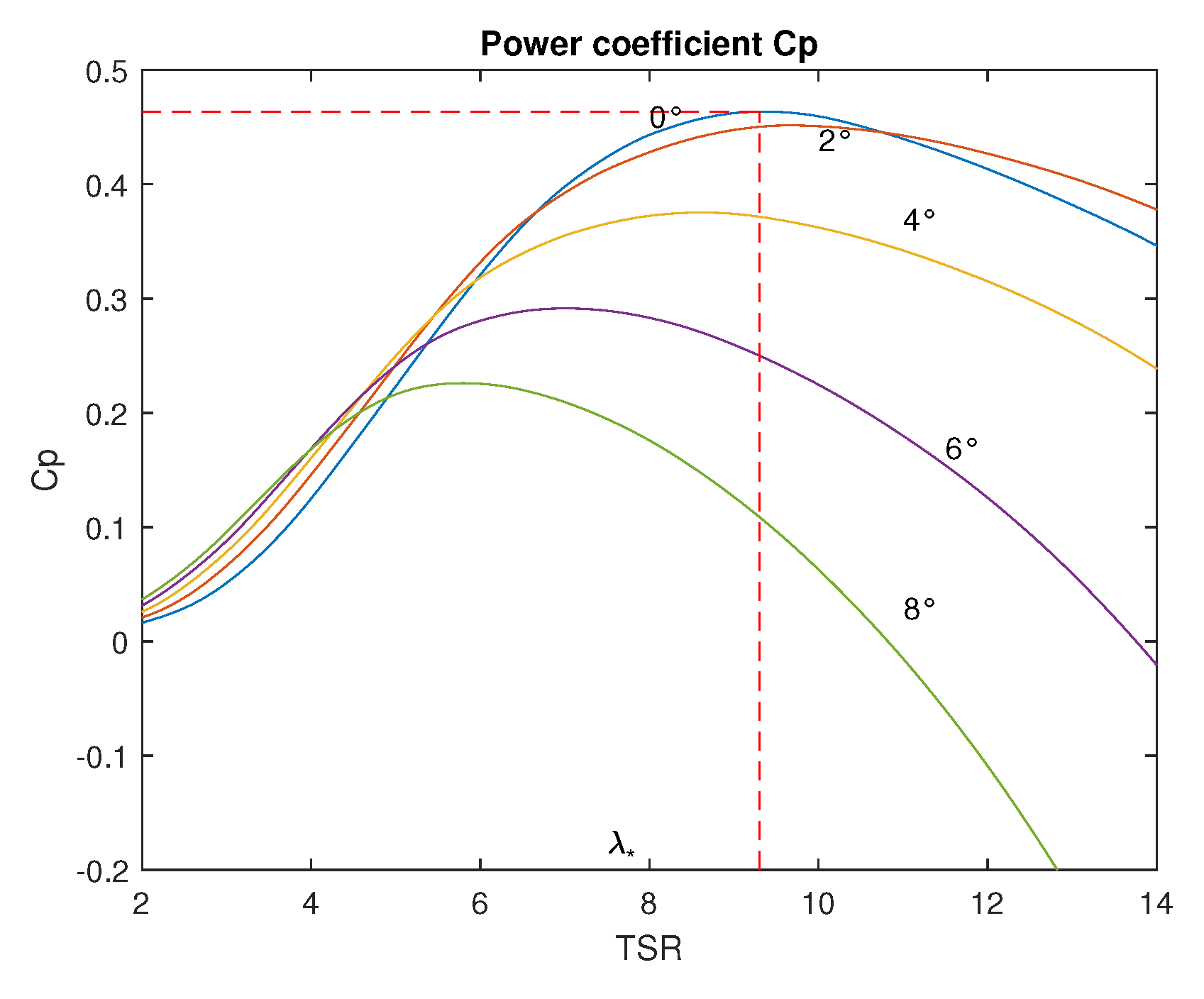
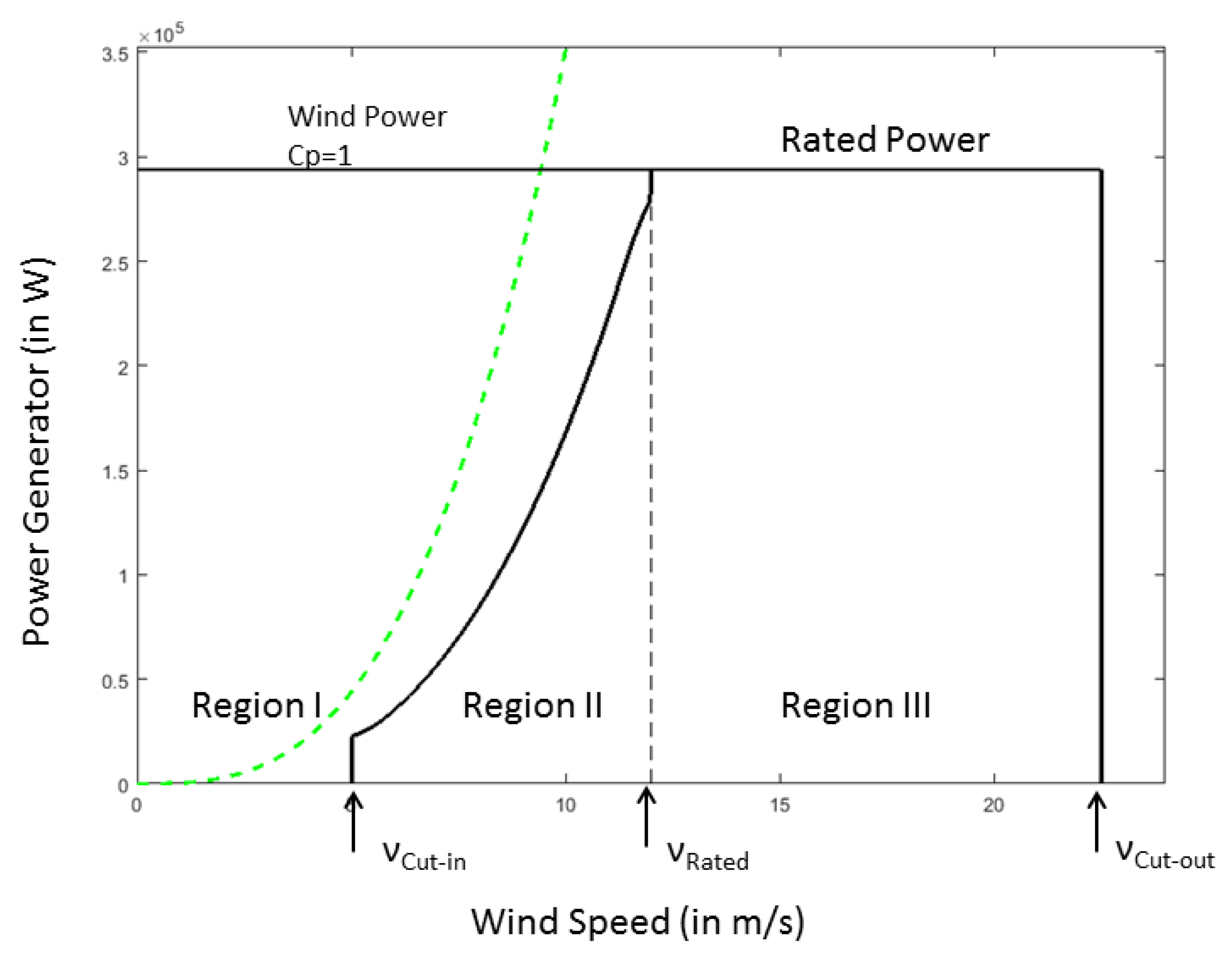
2.1. Wind Turbine Fundamentals

The power recovered on a wind turbine is lower than the wind power due to non-zero air velocities behind the wind turbine. A power factor called C p is then defined as the ratio of the power of the wind turbine divided by the power of the wind. The power extracted from a wind turbine is expressed by the following equation.
P = C p ( λ , β ) P w = 1 2 ρ π C p ( λ , β ) R 2 v 3
where ρ is air density, R is rotor radius, v represents the wind speed and P w is the kinetic power incoming to the turbine disk. The density of the air is linked by the pressure and the temperature according to the perfect gas law. The pressure and the temperature can evolve locally depending on the location of the wind turbines and hub height. These variations affect the values of the density of the air and therefore the power output. Taking into account this fluctuating parameter makes it possible to improve the power curves and therefore the operating point of the turbines [8]. C p ( λ , β ) is aerodynamic efficiency and is defined by a nonlinear function of the tip-speed ratio (TSR) λ and blade pitch angle β . The TSR is defined as
λ = ω R v
where ω is rotor speed. For each wind value, there is a rotor speed for which the C p is maximum and this value corresponds to the optimal tip-speed-ratio λ * . This is illustrated in Figure 2, which represents a typical λ β C p curve for AWT-27 wind turbine model. The calculation was performed using FAST Software (NREL, Golden, CO, USA). Data post-processing was done using MATLAB (The Mathworks, Natick, MA, USA). Table 1 presents a summary of AWT-27 configuration.

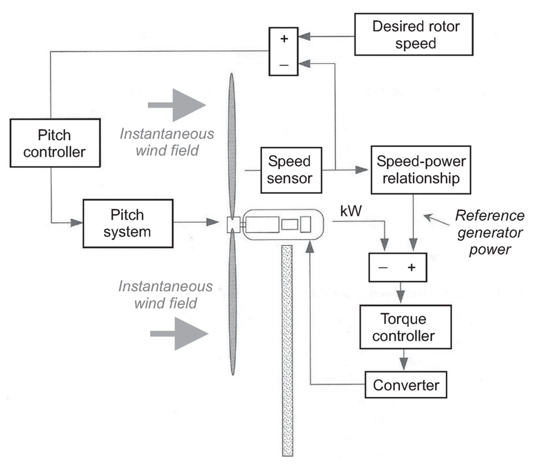
2.2. Standard Method Control

According to Johnson [10], a wind turbine has three levels of control system. The supervisory controller is charged to start up the wind turbine in the case of favorable wind and to shut down in the case of high winds. The intermediate level controls the wind turbine components, which includes generator torque, blade pitch control, yaw control and power electronic unit. Wind turbines cannot operate at all wind speeds due to physical limitations. High speed of rotation can cause an increase in mechanical forces on the machine and overheat the generator. This results in faster aging of the machine and a loss in the production of electricity. Variable speed wind turbines have three operating regions. Three distinct operations regions can be identified: below the cut-in speed region (Region I), the region between cut-in and rated speed (Region II) and the region above the rated wind (Region III). The transition zone between Region II and Region III, named transition region, is important in the control strategy in order to reach rated power.This is illustrated in Figure 3, which represents the power operating region for AWT-27. Calculations was performed using FAST Software (NREL, USA). Data post-processing was done using MATLAB (The Mathworks, Natick, MA, USA).
Region I corresponds to the start of the wind turbine. In Region I, the turbine is stopped due to the low level of wind velocities, which do not allow extracting significant power. Generally, the cut-in wind speed is 5 m/s. In Region II, the power content of the wind varies with the cube of the average wind speed (Equation (1)). The output power requires an appropriate control of torque and speed turbine to maximize energy production. The method used in this case is based on the maximum power point tracking (MPPT). The value of the power coefficient C p is maintained at its optimal value by varying speed turbine. It is common to use generator torque control and yaw control. The blade pitch is usually kept constant at an optimal value. Region II ends with the “rated wind speed”; this value corresponds to the wind speed which makes it possible to extract the rated power from the machine. Region III starts above the rated wind speed. In this region, the goal is to keep the power extracted as constant and equal to the rated power. As the rotor speed increases with wind speed, it is essential that the control system maintains the speed of the generator within the physical limits of the electrical and mechanical components. For this, the pitch angle of the blades is controlled to maintain the power at its rated value. As shown in Figure 4, the variable measured to generate either the pitch angle or the generator torque is the rotor speed Ω according to the desired operating objectives.
The control command allows the management and the interaction of the different elements of the floating wind turbine with the meteorological conditions. The increase in machine performance is due to improvements in control strategies. An effective strategy is to minimize mechanical stress in high wind conditions and maximize energy recovery for low winds to cover a larger production range. In the case of floating wind turbines, control strategies can also be used to reduce the movements of the platform.

2.3. Generator Torque Control

When the wind speed is in Region II, the generator torque controller is used to maximize the generated power. To reach this objective, the controller operates the turbine by accelerating or decelerating rotor at near the optimum power efficiency C p m a x . The turbine is operated at a constant TSR λ * . The torque control settings are equal to K gain by rotor speed squared:
τ g = K ω 2
where K is given by
K = 1 2 ρ π R 3 C p m a x λ * 3
The optimum TSR corresponds to the maximum power coefficient C p m a x . The dynamic representation of a rigid-body model of a wind turbine can be described according to the equation:
J ω . = ( τ a e r o τ g )
where
τ a e r o = 1 2 ρ π R 3 C p ( λ , β ) λ 3
so
ω . = 1 2 J π ρ R 3 ω 2 C p ( λ , β ) λ 3 C p m a x λ * 3
Here, the optimal TSR λ * corresponds to the maximum power coefficient. According to the equation, it is obvious that the two pairs compensate each other in order to keep the TSR constant, by accelerating or decelerating the rotor. This control is popular and simple to design. As mentioned in [12], this solution is inaccurate because this method depends on the wind as an input. Even if the constant gain K is determined precisely, the variations of wind force the turbine to operate sub-optimally. The author observed that tracking the rotor speed strictly with an unknown wind speed in Region II generates mechanical stresses within the transmission chain.

2.4. Power Optimization Control

The wind speed remains a parameter with strong variations; its effective values are difficult to measure. To compensate for this inaccuracy, other methods have been developed such as Perturb and Observe (P&O) control, power feedback feedback (PSF), and sliding mode control. Other methods based on algorithms are becoming more widely available in wind turbine controls such as Neural Network (NN) and Fuzzy Logic (FL).
Abdullah et al. [13] described the PSF control. This method to reach optimum point is obtained by experimental results. As outlined in [14], P&O has the advantage of not depending on knowledge of the characteristic curves of the wind turbine. The turbine power and turbine speed changes as a result of variations in wind velocity. This method is based on perturbing the turbine speed in small steps and observing the resulting changes in turbine mechanical power. The algorithms check the signs of rotor speed Δ ω . The speed is either incremented in small steps if turbine power P ( ω o p t ) > 0 and decremented as long as P ( ω o p t ) <0. However, this method fails to reach MPPT in large inertia wind turbines and smaller step sizes increase the efficiency but reduce the convergence speed. The sliding mode technique consists in bringing the state trajectory of a system to the sliding surface and making it switch with appropriate switching logic around it to the optimal point. The authors of [15,16] dealt with the sliding method associated with MPPT algorithm used to reach the peak power. The results show a good regulation of the power and a reduction of the mechanical forces. However, this strategy may take time to converge and be less effective when the wind speed changes quickly. In [17], a neural network model is used to optimize torque control in Region II. The results show a better performance for tracking the optimal torque thanks to the learning capacity of the NN model.
In [18,19], the authors mixed methods based on NN and fuzzy logic. This hybridization called adaptive neuro-fuzzy inference system (ANFIS) is used to calculate the power coefficient and track the maximum power point.
One of the limits of this concept is its cost in calculation. These algorithms need many data to learn in order to fulfill their goals. Wind turbines must therefore be able to return a lot of information (wind speed, wave characteristics, blade positions, etc.) to its algorithms. The increasing of the sensor number leads to the decreasing of system reliability.

2.5. Collective Pitch Control

In various publications on modeling wind turbine control, when the wind speed reaches Region III, the system has to regulate the power around a rated value to not exceed electrical and mechanical design loads. In the traditional control scheme, these objectives are fulfilled by holding the torque constant, while changing the blade angles regulates the generator speed to the target value.
Most of installed wind turbine use PI controller with constant coefficients [2] to adjust rotor speed and power The dynamic variations of the wind generates a nonlinear model. The use of constants in the regulation of the system is generally problematic. For this, the PI is reinforced by a control process called gain scheduling (GS). As underlined in [2,20], the principle is based on the linearization of the system at operating points in order to get as close as possible to the nonlinear behavior of the system.
Proportional integral derivative (PID) control is the most used algorithm method in the industry. Its popularity is due to its simplicity and robustness. PID method uses a closed loop with feedback to correct the error between the requested value and the measured value. The corrective gains then make up for its errors. Despite its effectiveness, this model has its limits. PID control is not suitable for multiple-input and multiple-output (MIMO) systems. The differential equations used to represent the system become more complex with the number of input and output. Second, PID gains based on constants are limited in the case of nonlinear systems.
The disadvantage of strategies based on collective pitch control is providing similar aerodynamic properties to all their trajectories. However, the local variations of the wind disturb differently the blades according to their positions in the rotation planes. Another problem that requires blade control to be the most optimized is the negative damping effect. This effect appears after a combination of dynamic loads and pitch control. This effect is explained by the speed of regulation of the blades greater than the tower motion. In [21], Larsen took into account the structure natural frequencies to determine the control parameters.

3. Limitations and Problems for FOWT

In response to strong winds and sea conditions, floating wind turbines require strict reliability criteria. This demand therefore requires a precise forecast of the movements and forces associated with environmental loads. The aerodynamic forces generate a thrust on the rotor, which is then transmitted to the entire structure. These efforts then affect the stability of the platform. The current model of collective control of the blades does not allow taking asymmetric loads into account. The same problem occurs in the case of hydrodynamic loads. The control methods then commonly used in the onshore wind industry are lacking. Additional parameters on the position of the platform, the environmental conditions, the tensions in the anchor lines, and the structural loads must appear in the control loops.

3.1. Aerodynamics

The variability of the wind profile in magnitude and direction causes asymmetric aerodynamic loads that vary spatially through the rotor disk. Currently, the trend is towards several megawatt scale WT, which increases the wind variation on the vertical and therefore the asymmetry of the aerodynamic loads. Additionally, the tower shadow implies an imbalance in the rotor loads. The airflow becomes more turbulent around the tower of the turbine, which creates abrupt movements on the blades. Cyclic loads (i.e., centrifugal force and gravitational force) damage the blades until they rupture. Gyroscopic forces can induce micro-cracking in composite blades . These effects are generalized for all types of wind turbines, whether onshore or offshore fixed bottom wind turbines.
In the case of FOWT, theses aerodynamic loads create movements directly on the floating platform that further increase structural fatigue. An important dynamic of the floating system is the pitching motion caused by the wind. The authors of [2,21] showed that these types of controls can cause negative damping problems caused by blade angle control beyond rated speed. The consequences of this negative damping materialize on the pitch behavior of the wind turbine: the negative damping related to the aerodynamic forces may become greater than the radiation damping or viscous on the platform. This anomaly causes instability. The standard control strategy applied to the wind turbine in Region III is the angle change of the blades. This strategy reduces the thrust when the wind increases by modifying the attack edges of the blades. Jonkman [2] tested several control strategies involving torque control and blade control for a high-power turbine installed on a floating barge. Strategies based on PI gain scheduling did not reduce pitch. The basic controllers show their limits in the case of floating systems.

3.2. Hydrodynamics

In the offshore environment, the presence of additional forces must be considered. Radiation and diffraction are the results of dynamic behavior caused by waves. Additionally, currents induce stationary and oscillating forces. These hydrodynamic forces contribute to the dynamics motion the floating platform. The motions of the floating wind platform are classically three translations (heave in the vertical, sway in the lateral, and surge in the axial) and three rotations(yaw about the vertical axis, pitch about the lateral, and roll about the axial). The x axis is facing the main wind and wave direction. A floating wind turbine introduces additional control objectives aimed at reducing rotational motion as well as linear displacements . Both external loads and the motions and their derivatives induce internal stresses in the structure. The bending moments created by these efforts can damage the support elements of the wind turbine (tower and nacelle). The value of these moments are closely related to the size of the wind turbine. In an offshore environmental context, calculating hydrodynamic forces remains a complex task. Nevertheless, despite the stochastic behavior of the waves, two approaches make it possible to estimate the hydrodynamic forces. The first approach is a deterministic analysis and relies on three variables: wave height, period and depth. The other approach, based on probabilistic theories, rests on the wave energy’s spectrum [22]. Two main formulations are available to calculate the hydrodynamics loads: the Boundary Element Method (BEM) generally in a linearized context and in the frequency domain, and the Morison formulation. Depending on the shape and size of the floater, one or both of these methods can be used.
Regulating these movements requires more effective control strategies than the classic collective blade pitch and torque control. In the classical design approach, to control each element separately by a control loop is not adapted to the additional DOF involved in FOWT.

4. Strategies Suitable for Problems Specific to FOWT

4.1. Individual Pitch Blade

Because collective control of blade attack angles is not adapted to local wind variations and the “tower clearance” effect [23], individual pitch control is proposed in the literature for fixed OWT. In [24,25], FL and NN control is combined with individual pitch control. These methods allow improving the management of power fluctuations, aerodynamic loads, local wind variations, rotor speed and generator torque fluctuations. Even if this kind of control allows significant improvements on mechanical loads and disturbances reduction, models presented in these articles are applied on on-shore WT and thus do not reflect the dynamic behavior of FOWT. To increase the platform stability, individual pitch control has also been proposed for FOWT. Some papers [26,27,28] propose using an individual control of the blades to reduce the loads. The conclusions of the studies show a decrease of the movements of the platform and consequently an improvement of stability.
However, the individual control of the blades increases the number of degrees of freedom (DOF), which complicates the control schemes. Pitch actuators’ reliability is strongly decreased due to their constant and severe use. The blade pitch control, as explained in these papers, cannot reduce motion structure and tower loads at the same time.

4.2. Structure Control

Industry and academia propose a method to mitigate motion of floating platform and consequently the structural loads. Inspired by O&G and shipbuilding industry, there are three main methods of structural controls: passive, semi-active and active. Passive control is the simplest solution where the system uses a tuned mass–spring–dampers (TMD). No energy is needed for its operation. However the use of constant parameters in the TMD limits the use of the system. The system is regulated to absorb specific excitation frequencies. A TMD system absorbs a portion of the energy along a given axis. Many degrees of freedom increase the complexity (related to the number of axis to be controlled) of the TMD systems to be installed in the platform.
A control algorithm can be used to modify the TMD parameters to improve the stability as a function of the platform motion. Such a choice of system offers better performance than passive method.
This last concept is the most effective in terms of control of the structure. The system is based on moving a mass through an actuator. The displacement of the mass counteracts the structure motion. The implementation of such a system requires providing energy for the actuator and a very efficient control of the mass motion. Lackner [29] investigated a passive and active structural control system on a floating barge. The proposed control is called hybrid mass–damper (HMD) and is a combination of both systems: it is a one-mass system moved by actuator. Both systems are placed in the nacelle of the wind turbine. The results show a reduction in dynamic loads within the structure. The proposed system offers better performance than the passive system. Nevertheless, the energy balance between the consumption of the active system and the energy produced by the rotor becomes negative in Region I. For a spar buoy FOWT, Si et al. [30] simulated the dynamic response of a TMD model placed in the tower. In [31], the authors simulated the dynamic behavior of a spar structure integrating a TMD in each blade, the nacelle and the tower following a semi-active method. In [32], the authors used a robust controller called H to optimize the controller gain. The TMD is placed on the platform to reduce the oscillations induced by dynamic loads. The conclusions are similar in the various publications: a reduction in dynamic loads but degraded performance for winds below the rated wind speed. Another alternative in active structural control is the method called tuned liquid column damper (TLCD). Here, the principle is to replace the spring–damper system with a liquid. In [33], a U-shaped tube with liquid inside is placed on the orthogonal plane of the platform roll axis. The author confronted two methods: a semi-active control and a passive control for controlling the liquid transfer. In the first case, the head loss coefficient is constant and, in the second case, it is variable as a function of time and can be controlled. This coefficient corresponds to the dissipation, by friction, of the mechanical energy during the movement of the liquid. The results show a significant improvement of system stability with an advantage for the semi-active method. However, in this publication, the aerodynamic effects of wind on the rotor are not taken into account.

5. Adapted Strategies for FOWT

Today’s challenge for floating offshore wind is to optimize the production in different wind region and reduce the cost of maintenance and operation. To fulfill the objectives, it is possible to rely on many innovative control strategies developed for the industry. Based on new generation algorithms and optimization techniques, these multi-objective strategies are used in industrial application to control complex nonlinear systems and can be used to improve the generated power and the reduction of structural loads. This section deals with advanced control methods which can be used in FOWT. Most of the literature on FOWT is focused on platform design, dynamic loads, and stability analysis. It can be noticed that few papers propose innovative control strategies for floating turbines. However, dynamic system control has been present in the industry for many years.
The linear quadratic Gaussian (LQG) method is used in [26,34] for control, which is based on a state representation of the system. The results show a significant reduction in bending moment without compromising power output. Model Predictive Control (MPC) is used when a PID controller becomes insufficient. This technique predicts future behavior thanks to a dynamic model implanted inside the controller. In [35], the authors tested the MPC method on an individual blade control strategy. The MPC method is compared against the work of Jonkman [2]. The results show significant improvements in electrical power and a dynamic load mitigation. Nonlinear model predictive control with collective pitch angle has been adapted on a FOWT, ns the results show good performance [36]. Some of these control methods have been simulated on off-shore wind turbines. They are used to control the blades pitch or the torque to improve performance and stability. The last lines of Table 2 refer to more advanced algorithms in terms of optimization and adaptation. Fuzzy logic (FL) can be used for on-shore WT control. In [37,38], the FL control is used to reduce the structural vibration. In [39], the method is applied to the pitch control of the blades for an onshore wind turbine. Simulation results show improved response and better accuracy of the speed control.
Other techniques can be imagined to improve the control of FOWT. For example, mooring is a key system that plays a key role in maintaining the position of the floating structure.

6. Evaluation

It appears in the literature that the goal in the wind industry is to lower costs, improve the reliability of components, and extract high quality power. From this observation, many control strategies can be used to control the system in the different wind regions of Figure 3. These points are even more challenging for the floating offshore wind turbine context due to its complicated environment and supplementary DOFs.
Different control method used in Region II are summarized and compared in Table 2. The main objective is to track the maximal power operation point. Some methods are not suited to large wind turbine constraints and large inertial forces, especially methods that use torque to determine the optimal point. Strict tracking of the optimal operating point in terms of power can generate undesirable vibrations in the transmission chain. These torsion forces, which are fluctuating due to wind changes, can lead to failure of the system. A hybrid model using both torque and pitch control allows combining decreased effort with high quality power generation. Smarter methods based on the use of artificial intelligence can be implemented but require a large amount of real-time data from the system.
For high speed wind, Table 3 lists the different methods to regulate speed at rated power and mitigate mechanical constraints. Most of the methods presented above are based on linear theory. They are effective around a limited number of operating points. For other methods, real-time wind measurements are needed to act accordingly. PID is simple to implement, but its primary limitation is its architecture based on a SISO. Given the number of DOFs involved in floating offshore, only MIMO models can be relevant to avoid control loop succession.
Gaussian quadratic linear control methods seem to offer an optimal solution. In addition, this type of methods offers a good level of robustness in the case of nonlinear or multi-variable systems. However, the disturbances on the measured signals due to the stochastic properties of the turbines can deteriorate the control. AI based methods provide more stability and allow better control of nonlinear and multi-variable systems. The Fuzzy Logic method allows a smoother control of blade angles. However, the number of used grades exponentially increases the number of rules to be written. Stochastic properties of the wave and wind can be better predicted by the use of a predictive method. The results show a significant decrease in structural costs and an optimization in the energy production. Nevertheless, these methods can have a significant negative impact on the reliability of the turbines because many sensors must be used, such as LIDAR (light detection and ranging), or forces sensor on the different components.

7. Conclusions

Challenges and trends of strategies for FOWT control are presented in this paper. Control methods have constantly evolved to adapt to the needs of the industry. Even if FOWT technologies are still in development, it is obvious that FOWT control objectives are quite different from the control objectives related to classical WT because the system has supplementary degree of freedom related to platform stability. Thus, an efficient control for FOWT requires controling more system variables and to use more control systems. For example, individual pitch control systems or structural control systems can be used in addition ti classical turbine speed control to improve the behavior and the power production of the FOWT system. Other innovative solutions can perhaps be used such as dynamic control of the mooring system.
Methods based on a SISO control such as classical PI or PID models are no longer appropriate due to the increased number of variables to be controlled. Innovative methods based on innovative MIMO control, AI based method or predictive control seems promising to face the challenge of FOWT control and allows large-scale industrial deployment of these systems. To meet the challenge of industrial deployment, floating wind turbines must lower their maintenance costs. To guarantee the energy production goals for such systems, several solutions can be implemented. Specific objectives, for example requirements on stability and mechanical fatigue, have to be taken into account. It can be done, in the design steps, using complex numerical simulation tools that allow taking into account the behavior of the system . These tools must be used to determine optimal solutions coupling system design and control strategies in terms of stability and mechanical strength. The improvement of sensor technologies as well as the management of their data gives the possibility of using more complex and smart control systems.

Author Contributions

T.S. carried out the state of the art review and analyzed the main data; J.F.C., M.B., and M.L.B. supervised the whole research procedure.

Funding

This research received no external funding.

Conflicts of Interest

The authors declare no conflict of interest.

Abbreviations

The following abbreviations are used in this manuscript:
FOWTFloating Offshore Wind Turbine
MIMOMultiple Input Multiple Output
O&GOils and Gas
DOFDegrees Of Freedom
TMDTuned Mass Damper
PIDProportional Integral Derivative
TSRTip-Speed Ratio
SISOSingle Input and Single Output
TLCDTuned Liquid Column Damper
MPCModel Predictive Control
LQGLinear Quadratic Gaussian
NNNeural Network
FLFuzzy Logic
P & OPerturb and Observe
MPPTMaximum Point Peak Tracking
LIDARLight Detection and Danging
Nomenclature
Rrotor radius, m
vwind speed, m · s 1
ρ air density, kg · m 3
β pitch angle of the blades, degrees
ω rotor speed, rad · s 1
Jturbine inertia, kg · m 2
τ torque, N · m
Cp( λ , β ) power coefficient
λ Tip Speed Ratio

References

  1. Ohlenforst, K.; Sawyer, S.; Dutton, A.; Backwel, B.; Fiestas, R.; Lee, J.; Qiao, L.; Zhao, F.; Balachandran, N. GWEC GLOBAL WIND REPORT 2018; GWEC: Brussels, Belgium, 2018. [Google Scholar]
  2. Jonkman, J.M. Dynamics Modeling and Loads Analysis of an Offshore Floating Wind Turbine; Technical Report; National Renewable Energy Lab. (NREL): Golden, CO, USA, 2007. [Google Scholar]
  3. Cruciani, M. The expansion of offshore wind power in the North Sea: A strategic opportunity for the European Union. Econ. Policy Energy Environ. 2018. [Google Scholar] [CrossRef]
  4. Freeman, K.; Hundleby, G.; Nordstrom, C.; Roberts, A.; Valpy, B.; Willow, C.; Torato, P.; Ayuso, M.; Boshell, F. Floating Foundations: A Game Changer for Offshore Wind Power. Available online: https://www.irena.org/-/media/Files/IRENA/Agency/Publication/2016/IRENA_Offshore_Wind_Floating_Foundations_2016.pdf (accessed on 23 September 2019).
  5. Bulder, B.; Van Hees, M.T.; Henderson, A.; Huijsmans, R.; Pierik, J.; Snijders, E.; Wijnants, G.; Wolf, M. Study to feasibility of and boundary conditions for floating offshore wind turbines. ECN, MARIN, TNO, TUD, MSC, Lagerway the Windmaster 2002, 26, 70–81. [Google Scholar]
  6. International Electrotechnical Commission; Technical Committee 88. Wind Turbines. Eoliennes. Part 3, Partie 3, Part 3, Partie 3; International Electrotechnical Commission: Geneva, Switzerland, 2009; OCLC: 316432209. [Google Scholar]
  7. Skaare, B.; Hanson, T.D.; Nielsen, F.G. Importance of control strategies on fatigue life of floating wind turbines. In Proceedings of the ASME 2007 26th International Conference on Offshore Mechanics and Arctic Engineering. American Society of Mechanical Engineers Digital Collection, San Diego, CA, USA, 10–15 June 2007; pp. 493–500. [Google Scholar]
  8. Pandit, R.K.; Infield, D.; Carroll, J. Incorporating air density into a Gaussian process wind turbine power curve model for improving fitting accuracy. Wind Energy 2019, 22, 302–315. [Google Scholar] [CrossRef]
  9. Poore, R. NWTC AWT-26 Research and Retrofit Project-Summary of AWT-26/27 Turbine Research and Development; Technical Report; National Renewable Energy Lab.: Golden, CO, USA, 2000. [Google Scholar]
  10. Johnson, K.E.; Pao, L.Y.; Balas, M.J.; Fingersh, L.J. Control of variable-speed wind turbines: Standard and adaptive techniques for maximizing energy capture. IEEE Control Syst. Mag. 2006, 26, 70–81. [Google Scholar]
  11. Simani, S. Overview of modelling and advanced control strategies for wind turbine systems. Energies 2015, 8, 13395–13418. [Google Scholar] [CrossRef]
  12. Johnson, K.E. Adaptive Torque Control of Variable Speed Wind Turbines; Technical Report; National Renewable Energy Lab.: Golden, CO, USA, 2004. [Google Scholar]
  13. Abdullah, M.A.; Yatim, A.; Tan, C.W.; Saidur, R. A review of maximum power point tracking algorithms for wind energy systems. Renew. Sustain. Energy Rev. 2012, 16, 3220–3227. [Google Scholar] [CrossRef]
  14. Barakati, S.M.; Kazerani, M.; Aplevich, J.D. Maximum power tracking control for a wind turbine system including a matrix converter. IEEE Trans. Energy Convers. 2009, 24, 705–713. [Google Scholar] [CrossRef]
  15. Pan, T.; Ji, Z.; Jiang, Z. Maximum power point tracking of wind energy conversion systems based on sliding mode extremum seeking control. In Proceedings of the 2008 IEEE Energy 2030 Conference, Atlanta, GA, USA, 17–18 November 2008; pp. 1–5. [Google Scholar]
  16. Beltran, B.; Ahmed-Ali, T.; Benbouzid, M.E.H. Sliding mode power control of variable-speed wind energy conversion systems. IEEE Trans. Energy Convers. 2008, 23, 551–558. [Google Scholar] [CrossRef]
  17. Wang, L.; Zuo, S.; Song, Y.; Zhou, Z. Variable torque control of offshore wind turbine on spar floating platform using advanced RBF neural network. Abstr. Appl. Anal. 2014, 2014, 1–7. [Google Scholar] [CrossRef]
  18. Petković, D.; Ćojbašič, Ž.; Nikolić, V. Adaptive neuro-fuzzy approach for wind turbine power coefficient estimation. Renew. Sustain. Energy Rev. 2013, 28, 191–195. [Google Scholar] [CrossRef]
  19. Meharrar, A.; Tioursi, M.; Hatti, M.; Stambouli, A.B. A variable speed wind generator maximum power tracking based on adaptative neuro-fuzzy inference system. Expert Syst. Appl. 2011, 38, 7659–7664. [Google Scholar] [CrossRef]
  20. Bagherieh, O.; Nagamune, R. Gain-scheduling control of a floating offshore wind turbine above rated wind speed. Control Theory Technol. 2015, 13, 160–172. [Google Scholar] [CrossRef]
  21. Larsen, T.J.; Hanson, T.D. A method to avoid negative damped low frequent tower vibrations for a floating, pitch controlled wind turbine. J. Phys. Conf. Ser. 2007, 75, 012073. [Google Scholar] [CrossRef]
  22. Molin, B. Hydrodynamique des Structures Offshore; Editions Technip: Paris, France, 2002. [Google Scholar]
  23. Kim, H.; Lee, S.; Lee, S. Influence of blade-tower interaction in upwind-type horizontal axis wind turbines on aerodynamics. J. Mech. Sci. Technol. 2011, 25, 1351. [Google Scholar] [CrossRef]
  24. Han, B.; Zhou, L.; Yang, F.; Xiang, Z. Individual pitch controller based on fuzzy logic control for wind turbine load mitigation. IET Renew. Power Gener. 2016, 10, 687–693. [Google Scholar] [CrossRef]
  25. Kang, M.J.; Kim, H.C. Neural Network Based Pitch Controller. In Proceedings of the World Congress on Electrical Engineering and Computer Systems and Science (EECSS 2015), Barcelona, Spain, 13–14 July 2015; pp. 1–6. [Google Scholar]
  26. Bossanyi, E.A. Individual blade pitch control for load reduction. Wind Energy Int. J. Prog. Appl. Wind Power Convers. Technol. 2003, 6, 119–128. [Google Scholar] [CrossRef]
  27. Namik, H.; Stol, K. Individual blade pitch control of floating offshore wind turbines. Wind Energy Int. J. Prog. Appl. Wind Power Convers. Technol. 2010, 13, 74–85. [Google Scholar] [CrossRef]
  28. Namik, H.; Stol, K. Performance analysis of individual blade pitch control of offshore wind turbines on two floating platforms. Mechatronics 2011, 21, 691–703. [Google Scholar] [CrossRef]
  29. Lackner, M.A.; Rotea, M.A. Structural control of floating wind turbines. Mechatronics 2011, 21, 704–719. [Google Scholar] [CrossRef]
  30. Si, Y.; Karimi, H.R.; Gao, H. Modelling and optimization of a passive structural control design for a spar-type floating wind turbine. Eng. Struct. 2014, 69, 168–182. [Google Scholar] [CrossRef]
  31. Dinh, V.N.; Basu, B.; Nagarajaiah, S. Semi-active control of vibrations of spar type floating offshore wind turbines. Smart Struct. Syst. 2016, 18, 683–705. [Google Scholar] [CrossRef]
  32. Li, X.; Gao, H. Load Mitigation for a Floating Wind Turbine via Generalized Structural Control. IEEE Trans. Ind. Electron. 2016, 63, 332–342. [Google Scholar] [CrossRef]
  33. Coudurier, C.; Lepreux, O.; Petit, N. Passive and semi-active control of an offshore floating wind turbine using a tuned liquid column damper. IFAC-PapersOnLine 2015, 48, 241–247. [Google Scholar] [CrossRef]
  34. Christiansen, S.; Knudsen, T.; Bak, T. Optimal control of a ballast-stabilized floating wind turbine. In Proceedings of the 2011 IEEE International Symposium on Computer-Aided Control System Design (CACSD), Denver, CO, USA, 28–30 September 2011; pp. 1214–1219. [Google Scholar]
  35. Raach, S.; Schlipf, D.; Sandner, F.; Matha, D.; Cheng, P.W. Nonlinear model predictive control of floating wind turbines with individual pitch control. In Proceedings of the 2014 American Control Conference, Portland, OR, USA, 4–6 June 2014; pp. 4434–4439. [Google Scholar]
  36. Schlipf, D.; Sandner, F.; Raach, S.; Matha, D.; Cheng, P.W. Nonlinear model predictive control of floating wind turbines. In Proceedings of the Twenty-Third (2013) International Offshore and Polar Engineering Conference, Anchorage, AK, USA, 30 June–5 July 2013. [Google Scholar]
  37. Tahani, M.; Ziaee, E.; Hajinezhad, A.; Servati, P.; Mirhosseini, M.; Sedaghat, A. Vibrational simulation of offshore floating wind turbine and its directional movement control by fuzzy logic. In Proceedings of the 2015 International Conference on Sustainable Mobility Applications, Renewables and Technology (SMART), Kuwait City, Kuwait, 23–25 November 2015; pp. 1–7. [Google Scholar]
  38. Wenzhong, Q.; Jincai, S.; Yang, Q. Active control of vibration using a fuzzy control method. J. Sound Vib. 2004, 275, 917–930. [Google Scholar] [CrossRef]
  39. Qi, Y.; Meng, Q. The application of fuzzy PID control in pitch wind turbine. Energy Procedia 2012, 16, 1635–1641. [Google Scholar] [CrossRef]
  40. Jeong, H.G.; Seung, R.H.; Lee, K.B. An improved maximum power point tracking method for wind power systems. Energies 2012, 5, 1339–1354. [Google Scholar] [CrossRef]
  41. Wright, A.D.; Fingersh, L. Advanced Control Design for Wind Turbines; Part I: Control Design, Implementation, and Initial Tests; Technical Report; National Renewable Energy Lab. (NREL): Golden, CO, USA, 2008. [Google Scholar]
  42. Dahbi, A.; Nait-Said, N.; Nait-Said, M.S. A novel combined MPPT-pitch angle control for wide range variable speed wind turbine based on neural network. Int. J. Hydrog. Energy 2016, 41, 9427–9442. [Google Scholar] [CrossRef]
Figure 1. Offshore wind floating foundation concepts From left to right, the three main concepts are represented: barge, spar, TLP and semi-submersible.
Electronics 08 01185 g001
Figure 2. Optimum power curve for AWT27 wind turbine.
Electronics 08 01185 g002
Figure 3. Operation regions of AWT-27 variable speed turbine.
Electronics 08 01185 g003
Figure 4. Wind turbine basics control loops [11].
Electronics 08 01185 g004
Table 1. Properties of AWT-27 turbine configuration [9].
Rating275 kW
Rotor Orientation, ConfigurationDownwind, 2 Blades
ControlVariable Speed, Collective Pitch
Rotor, Hub Height28.5 m, 42.6
Cut-in, Rated, Cut-out wind speed4.9 m/s, 17 m/s, 22.5 m/s
Rated Rotational Speed53 rpm
Table 2. Comparison of control method in Region II.
Control MethodVariable ControlledLimitsReferences
Optimal TSRTorqueSimple to implement.Wind measurements required[12]
Power signal FeedbackTorqueRequires the reference optimum power curve obtained from experimental results[13]
Perturb and ObserveTorqueEfficiency only for low inertia load wind turbine[14]
Sliding modeTorque and PitchProblem of convergence time with high variation of wind speed[15,16,40]
Adaptive controllerTorqueRequire knowledge of C p m a x and λ * [10,12]
Neural Network∖Fuzzy logicTorqueComplicate to implement (Unexplained behavior of the network,Hardware dependence)[13,17]
Table 3. Comparison of control method in Region III.
Control MethodStrategiesDescriptionReferences
PI (with Gain scheduling)Collective pitchRobust and simple to design[41]
Linear Quadratic GaussianIndividual pitchMulti-variable control, Kalman filter is used to estimate system states[26]
Fuzzy logicIndividual pitchCover a wider range of operating conditions, cheaper to develop[24]
Model predictive controlIndividual pitchMulti-processing input and output data in real time, ability to anticipate[36]
Neural NetworkIndividual pitchLearning ability in order to model nonlinear and complex system[25,42]

