1. Introduction
For microwave systems that require a compact size, a high-precision control, or a high power, undesirable signal crosstalk and leakage can lead to many problems. Poor transmitter/receiver isolation and strong inter-channel signal crosstalk degrade the system performance. For example, in theory, digital phased array systems based on Direct Digital Synthesis (DDS) can achieve very high phase adjustment accuracy (with a resolution of 12 bits or higher). However, the excitation vector error caused by inter-channel crosstalk seriously constrains the effective control accuracy of an actual system. For a dual-channel phased system with a 12-bit phase resolution, if the required maximum phase error is below +/− 0.5 LSB (0.044 degree), then the system must maintain a minimal channel isolation of 63 dB. It is difficult to achieve such an isolation performance for systems implemented or integrated using conventional microstrip lines or coplanar waveguides. Planar waveguide structures, such as the substrate-integrated wave-guide (SIW), tend to have good isolation characteristics, nonetheless due to relatively large size, it is difficult to integrate them at low-frequency, such as the C-band.
In [
1], one type of substrate-integrated coaxial line (SICL) prototype is proposed, and its propagation mode and characteristics are analyzed. A SICL is a planar coaxial line structure with good isolation characteristics. SICLs are compact in size and have been used for many RF and microwave components in recent years, including the coupler [
2], the ultra-wideband balun [
3], the power divider [
4,
5], the oscillator [
6], and the filter [
7,
8,
9,
10]. SICLs are also widely used in antenna feed networks, e.g., in [
11,
12,
13,
14,
15,
16,
17], the antennae fed by a SICL achieved good performances. The measurement results of the SICL–GCPW (Substrate Integrated Coaxial Line - Grounded CoPlanar Waveguide) transition [
18] and the empty-SICL–microstrip transition [
19] illustrate that a SICL is compatible with various surface structures, such as coplanar waveguides and microstrip lines. In [
20], the multichannel data transmission has been discussed by using SICL, showing that a SICL has good high-speed multichannel transmission characteristics. It should be noted that results about the crosstalk between SICLs are rare. When designing a microwave circuit concerning SICLs, however, it is important to know the real crosstalk between SICLs, although one knows it is theoretically very low.
To further promote the application of SICL and provide a reference value in a practical design, measurement and verification of its high isolation is of great necessity and significance. However, quantitative measurement and verification of ultralow crosstalk in a real test environment faces multiple challenges. In actual measurements, because the SICL’s intermediate conductor is located in the middle layer of the multi-layer printed circuit board (PCB), a transition structure is needed so as to convert the SICL with the test equipment. The transition and SMA port connectors will generate undesired radiation, leading to interference in a real measurement. In view of this, an effective suppression of the interference is key for the success of a measurement.
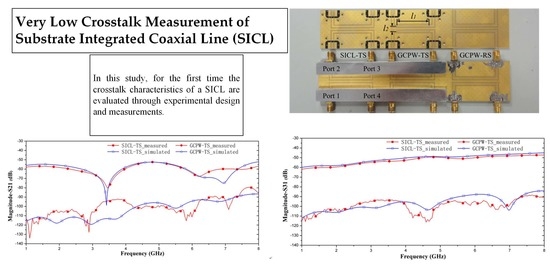
In the present study, an experimental design and measurements on the crosstalk characteristics of SICLs are performed and compared to that of GCPW. A method to suppress interference caused by leakages and radiation at the interfaces and structural transitions is introduced. The related measurement data are obtained to verify the superiority of a SICL in crosstalk performances.
2. Experiment and Structure Design
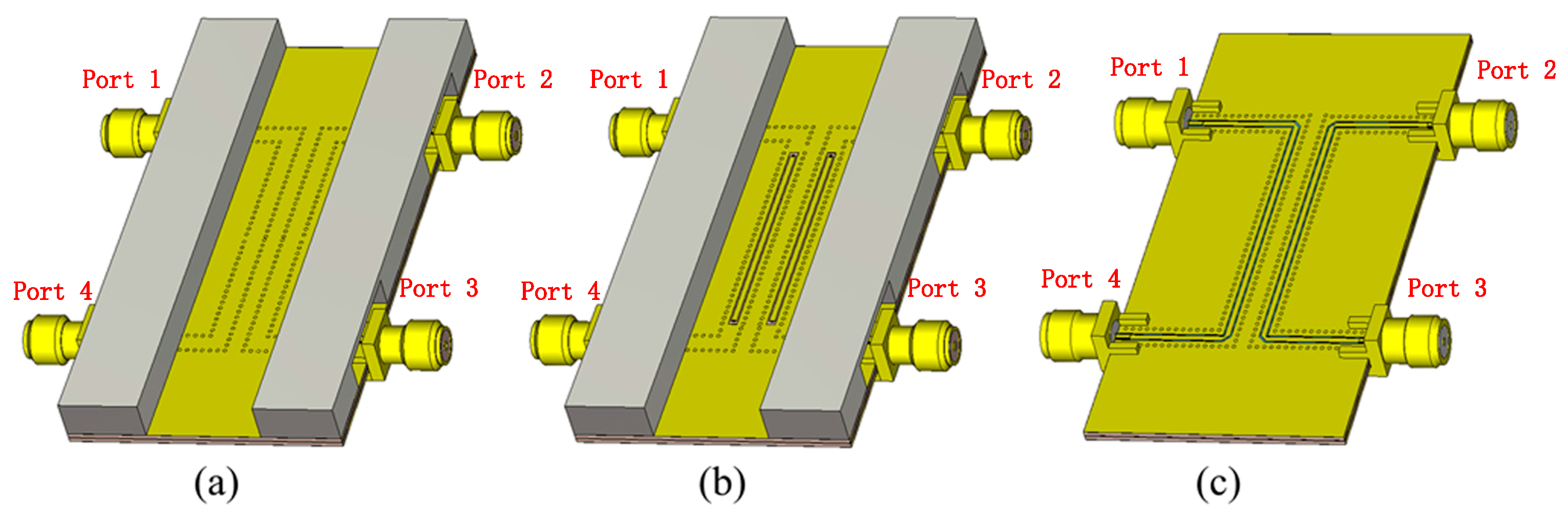
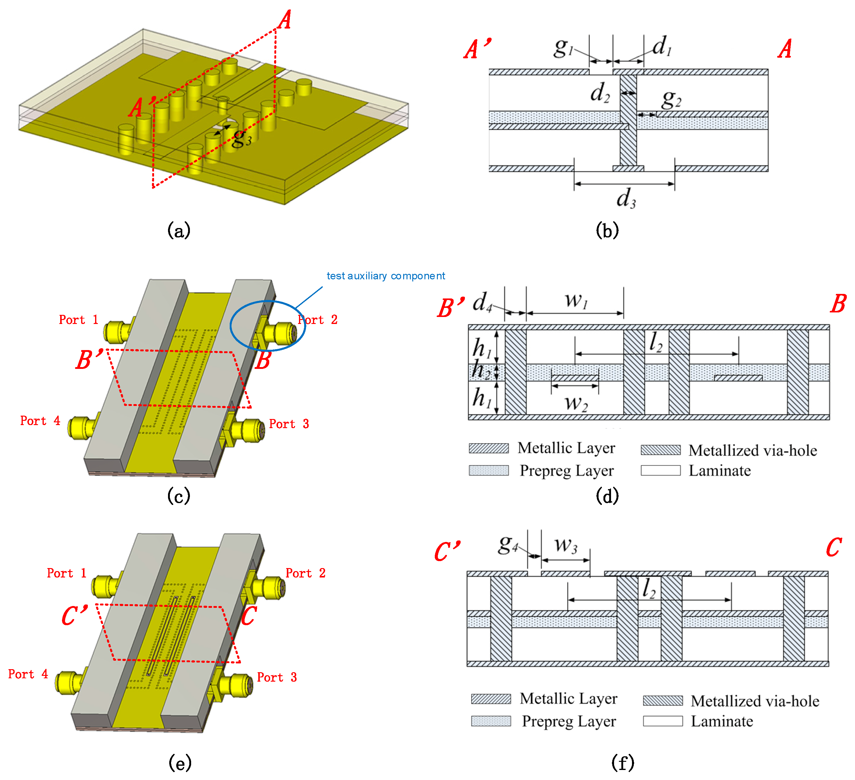
To measure crosstalks of SICL and GCPW, a SICL test set (SICL-TS) and a GCPW test set (GCPW-TS) were designed, and
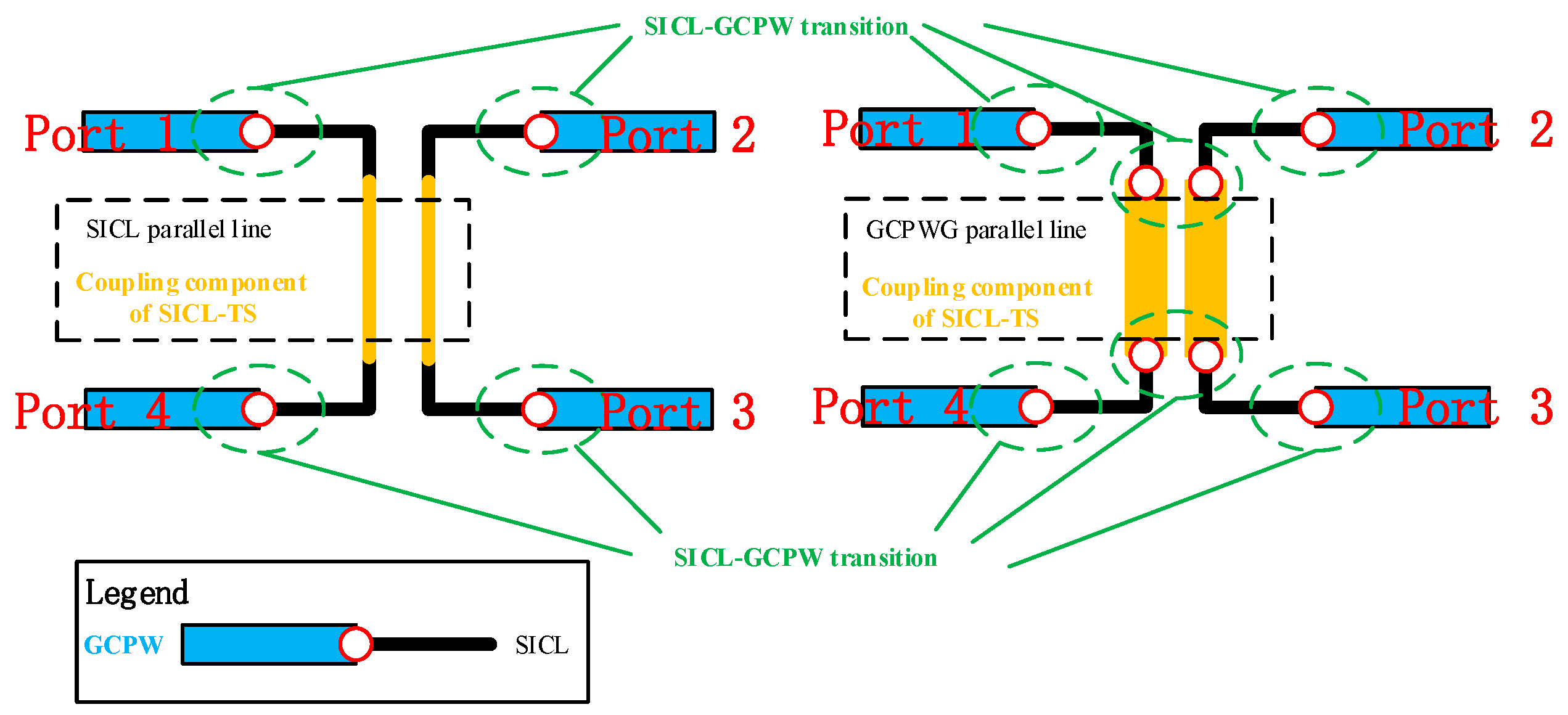
Figure 1a,b show models of their three-dimensional structures. Except for a SICL parallel coupling line, the SICL-TS was also equipped with test auxiliary components, including 4 SICL-GCPW transitions, 4 SMA port connectors, 4 90° bends and shielding structures. The GCPW-TS were equipped with a GCPW parallel coupling line and test auxiliary components, including 8 SICL-GCPW transitions, 4 SMA connectors, 4 90° bends and shielding structures. A SICL-GCPW transition was a conversion between a GCPW and a SICL. Shielding structures were properly designed to suppress the radiation from the SMA port connectors and the transitions. Differing from the SICL parallel coupling line, the GCPW parallel coupling line also included 4 SICL-GCPW transitions, as shown in
Figure 2.
Signal leakage from the SMA port connectors can approach or even surpass the crosstalk signal itself. To prevent signal leakage from generating interference with measurement results, the input/output ports for the same transmission line segment were installed on the same side of the PCB, and both the SICL and GCPW parallel coupling lines were composed of two segments of mirror-distributed U-shape transmission lines, as shown in
Figure 1 and
Figure 2.
Figure 3 shows the details of the SICL-GCPW transition and the cross-sectional structure diagram of the SICL and GCPW parallel coupling lines. Further,
Table 1 lists geometric parameters for the related structures.
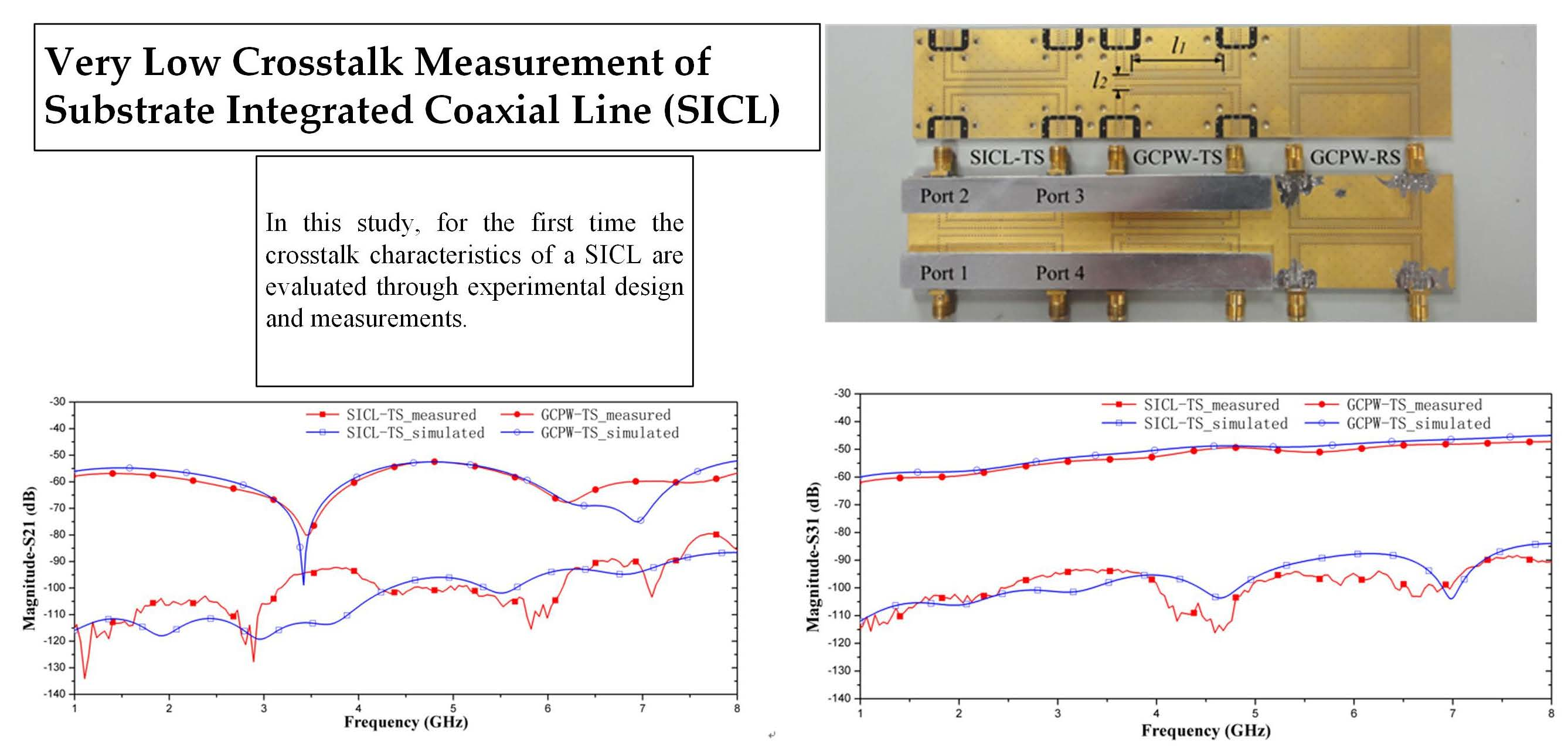
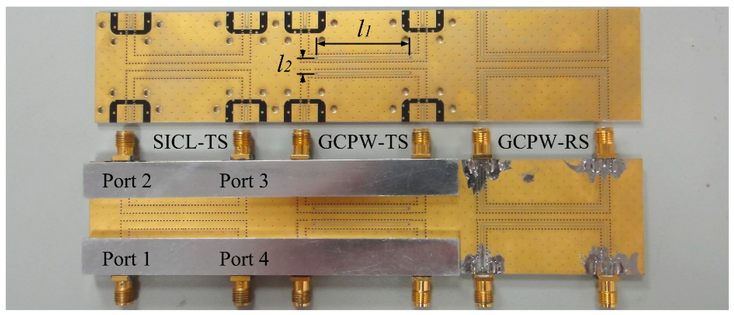
Figure 4 depicts the fabricated test sets. The length of parallel coupling lines was
l1 = 30 mm and the interval between conduction strip centers of coupling lines was
l2 = 5 mm. The shielding structures were made of aluminum and were fixed onto the PCB using screws. All the test sets were installed in parallel on the same piece of PCB to maintain the consistency of board material and manufacture processing. Standard PCB technology, using two layers of RO4003C laminates of the relative permittivity εr = 3.55 and thickness 0.51 mm, were adopted. The RO4450B prepreg with εr = 3.54 and thickness of 0.20 mm was used to bond the upper and the lower laminates.
To ensure comparability of the measurement results, both the SICL-TS and the GCPW-TS were equipped with the same SICL-GCPW transitions, the same SMA port connectors and shielding structures. The only difference between the SICL-TS and the GCPW-TS was the parallel coupling line in the middle, which was the sole variable to determine crosstalk differences between the SICL-TS and the GCPW-TS.
To evaluate the effect of four SICL-GCPW transitions in the GCPW parallel coupling line, a GCPW reference set (GCPW-RS), as shown in
Figure 1c, was also designed. The GCPW-RS has no SICL-GCPW transition, and only includes a GCPW-parallel coupling line, 4 SMA connectors and 4 contain 90° bends. Its parallel coupling line is exactly the same as that used for the GCPW-TS. Therefore, it is the SICL-GCPW transition that determines the crosstalk differences between the GCPW-TS and the GCPW-RS.
3. Simulated and Measured Results
Scattering parameters (S-parameters) were used to evaluate the crosstalk performances of different test sets. Simulation on the designed structures was performed with the electro-magnetic analysis software CST MICROWAVE STUDIO, and the results were used as references to the measured data. An Agilent E5071C vector network analyzer was used to measure the three sets of fabricated structures. Due to symmetry in these structures, only the data of S41, S31, S21, and S11 were plotted. The insertion loss of the three test sets is shown in
Figure 5. The maximum loss is less than −2 dB at 8 GHz. The SICL-TS has the lowest insertion loss compared to the other two.
The crosstalk characteristics of both the SICL-TS and the GCPW-TS are the consequence of joint impacts from the test auxiliary components and its parallel coupling line. Between these two factors, the factor leading to a stronger crosstalk will play a decisive role in determining the total crosstalk of the whole test set. Because the SICL-TS and the GCPW-TS have the same test auxiliary components, the crosstalk due to the test auxiliary components in the SICL-TS and the GCPW-TS are the same.
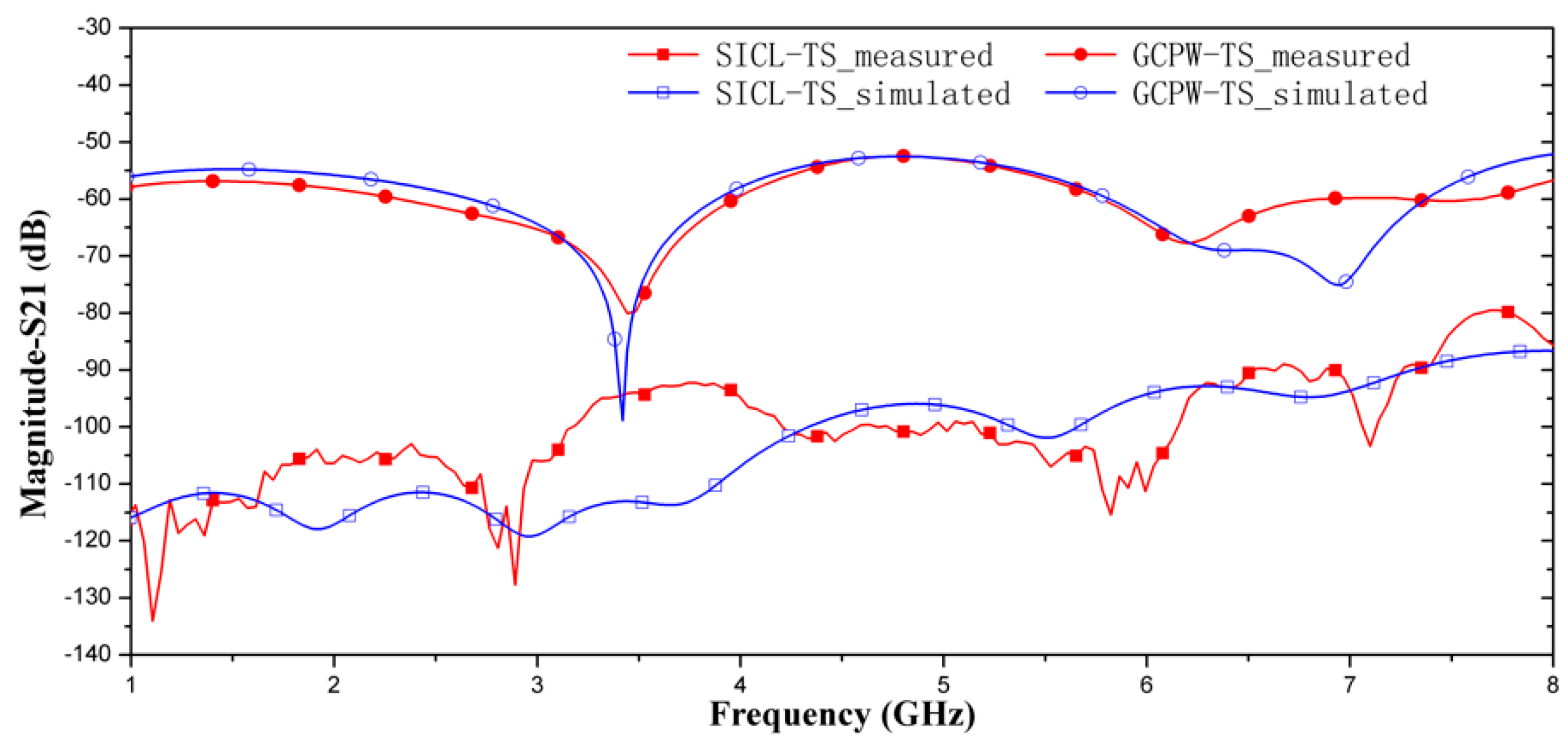
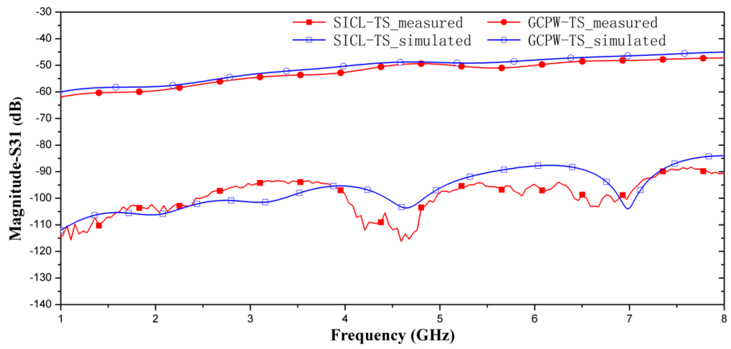
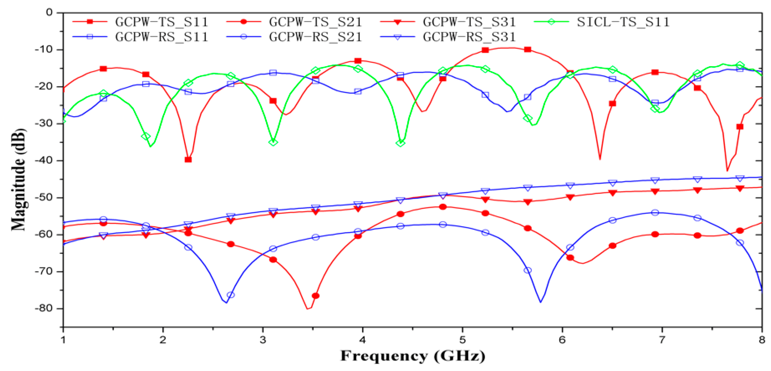
Figure 6 and
Figure 7 show comparisons of simulated and measured crosstalks between the SICL-TS and the GCPW-TS. Across the whole measured frequency band, the measurement results of the SICL-TS and GCPW-TS are consistent with the simulation in terms of magnitudes and trends. The crosstalk signals of the SICL-TS have low signal strength and a relatively low signal-to-noise ratio, leading to slight fluctuations in the data. As for the GCPW-TS, port 2 is similar to the coupled port of a line coupler in terms of its layout. Trap points of |S21| may arise under specific frequencies as shown in
Figure 5. Changing the coupling line length will shift the trap point locations but will not significantly change the maximum intensity.
The results in
Figure 6 and
Figure 7 indicate that the crosstalk of the SICL-TS is about −90 dB, and much smaller than the crosstalk of GCPW-TS, which is about −50 dB. In addition, because the total crosstalk of the SICL-TS is about −90 dB, the crosstalk of the test auxiliary components must be smaller than −90 dB. Therefore, the GCPW parallel coupling line contributes most of the total crosstalk of −50 dB in GCPW-TS. On the other hand, compared to the SICL parallel coupling line, the GCPW parallel coupling line has four extra SICL-GCPW transitions. To evaluate the crosstalk of GCPW accurately, the impacts of the SICL-GCPW transitions must be measured.
Figure 8 shows the measurement results of the GCPW-RS and the GCPW-TS. The S31 and S21 of the two sets are close to each other in terms of magnitude, indicating that the SICL-GCPW transition and shielding structures will not significantly impact the overall crosstalk of the GCPW parallel coupling line.
The above results verify that the SICL has much better crosstalk characteristics than the GCPW over all measured frequencies. At most of the frequencies, the differences of isolation performance between the two structures surpass 20 dB, and at low frequency, the maximum difference can surpass 50 dB.
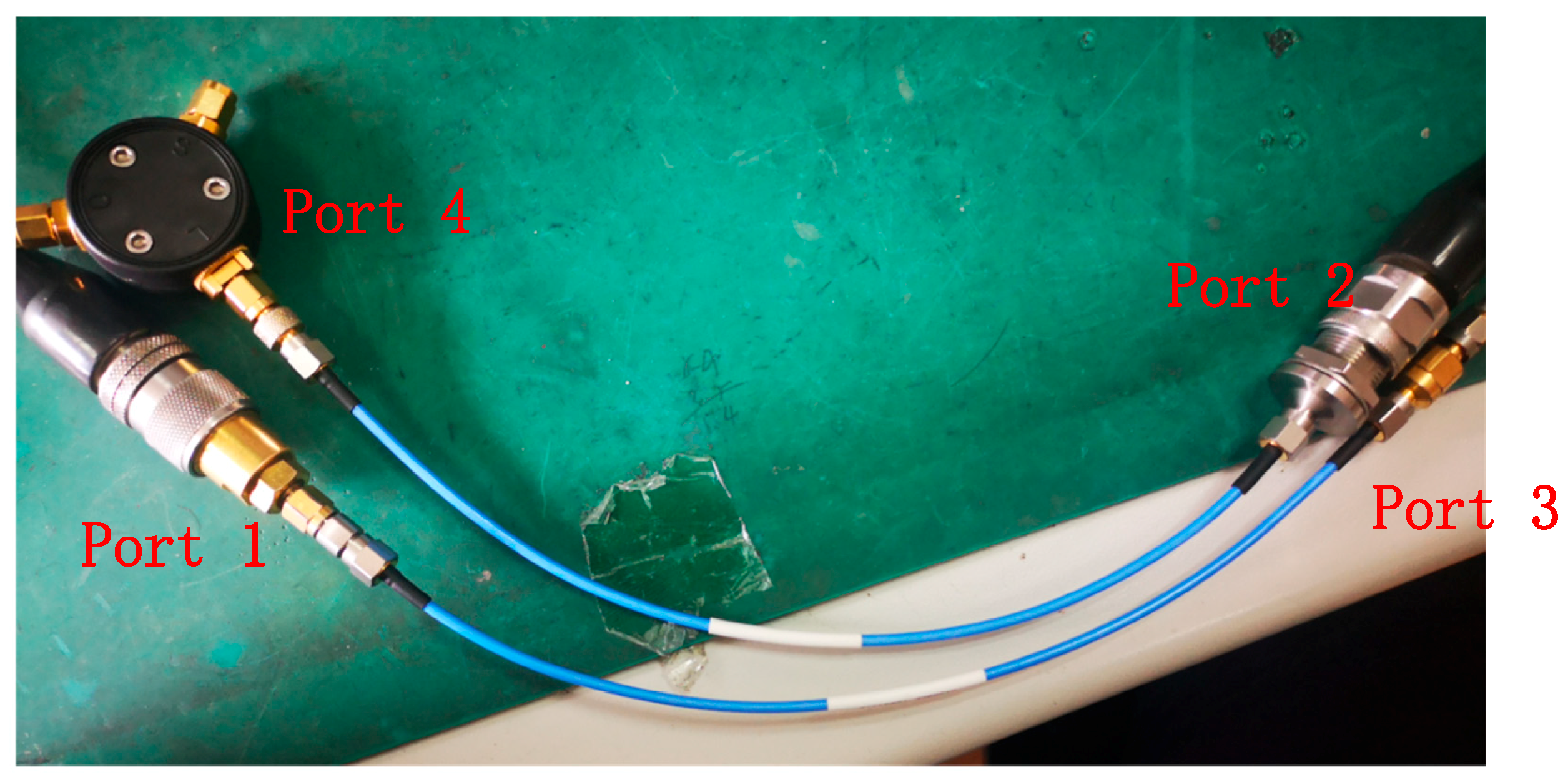
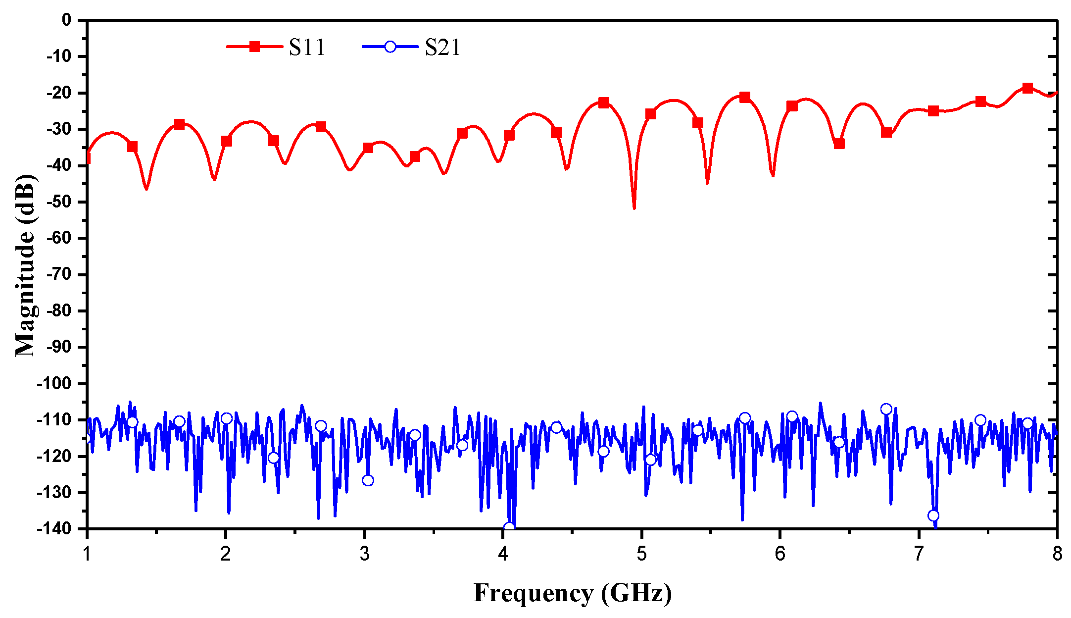
Finally, the crosstalk of the excellent coaxial lines were measured. The measurement environment is shown in
Figure 9, and the results are shown in
Figure 10. The results illustrate that both the crosstalk of the measurement system and the crosstalk of the excellent shielding coaxial line are lower, compared to crosstalk in the SICL-TS and the GCPW-TS. Therefore, the results of the measurement system are reasonable.
4. Conclusions
Based on the measurements, if the max (|S21|, |S31|) is used as isolation indicators, then the isolation between SICL parallel coupling line with a 5mm interval and 30 mm length is no less than 114 dB at 1 GHz, no less than 94 dB at 4 GHz, and no less than 85 dB at 8 GHz. Our data show that the isolation decreases at a rate of about 10 dB/octave as the operating frequency increases. The measured results will be good reference values for use in a practical design or when evaluating the accuracy of a simulation associated with SICLs.
Author Contributions
Conceptualization, X.Y.; data curation, C.L.; methodology, C.L.; software, L.Y. and H.Z.; validation, L.L. and L.Y.; and writing—original draft, C.L. and X.Y.
Funding
This research was funded by the National Natural Science Foundation of China, grant numbers 61801116, 61771127, and 61427801.
Conflicts of Interest
The authors declare no conflict of interest.
References
- Gatti, F.; Bozzi, M.; Perregrini, L.; Wu, K.; Bosisio, R.G. A novel substrate integrated coaxial line (SICL) for wideband applications. In Proceedings of the 2006 European Microwave Conference, Manchester, UK, 10–15 September 2006; pp. 1614–1617. [Google Scholar]
- Liang, W.; Hong, W. Substrate integrated coaxial line 3 dB coupler. Electron. Lett. 2012, 48, 35–36. [Google Scholar] [CrossRef]
- Zhu, F.; Hong, W.; Chen, J.X.; Wu, K. Ultra-Wideband Single and Dual Baluns Based on Substrate Integrated Coaxial Line Technology. IEEE Trans. Microw. Theory Tech. 2012, 60, 3062–3070. [Google Scholar] [CrossRef]
- Mukherjee, S. Design of Four-Way Substrate Integrated Coaxial Line (SICL) Power Divider for K Band Applications. In Proceedings of the 2017 IEEE MTT-S International Microwave and RF Conference (IMaRC), Ahmedabad, India, 11–13 December 2017; pp. 1–4. [Google Scholar]
- Merello, J.M.; Nova, V.; Bachiller, C.; Sánchez, J.R.; Belenguer, A.; Esbert, V.E.B. Miniaturization of Power Divider and 90° Hybrid Directional Coupler for C-Band Applications Using Empty Substrate-Integrated Coaxial Lines. IEEE Trans. Microw. Theory Tech. 2018, 66, 3055–3062. [Google Scholar] [CrossRef]
- Chen, Z.; Hong, W.; Chen, J.; Li, L. Design of A Push-Push and Push-Pull Oscillator Based on SIW/SICL Technique. IEEE Microw. Wirel. Compon. Lett. 2014, 24, 397–399. [Google Scholar] [CrossRef]
- Chu, P.; Hong, W.; Wu, K.; Chen, J.X.; Tang, H.J. A miniaturized Bandpass Filter Implemented with Substrate Integrated Coaxial Line. Microw. Opt. Technol. Lett. 2013, 55, 131–133. [Google Scholar] [CrossRef]
- Martinez, L.; Belenguer, A.; Boria, V.E.; Borja, A.L. Compact Folded Bandpass Filter in Empty Substrate Integrated Coaxial Line at S-Ban. IEEE Microw. Wirel. Compon. Lett. 2019, 29, 315–317. [Google Scholar] [CrossRef]
- Borja, A.L.; Belenguer, A.; Esteban, H.; Boria, V.E. Design and Performance of a High-Q Narrow Bandwidth Bandpass Filter in Empty Substrate Integrated Coaxial Line at Ku-Band. IEEE Microw. Wirel. Compon. Lett. 2017, 27, 977–979. [Google Scholar] [CrossRef]
- Cariou, M.; Potelon, B.; Quendo, C.; Cadiou, S.; Schlaffer, E.; Pessl, W.; Le Fevre, A. Compact X-Band Filter Based on Substrate Integrated Coaxial Line Stubs Using Advanced Multilayer PCB Technology. IEEE Trans. Microw. Theory Tech. 2017, 65, 496–503. [Google Scholar] [CrossRef]
- Yang, T.Y.; Hong, W.; Zhang, Y. An SICL-Excited Wideband Circularly Polarized Cavity-Backed Patch Antenna for IEEE 802.11aj (45 GHz) Applications. IEEE Antennas Wirel. Propag. Lett. 2016, 15, 1265–1268. [Google Scholar] [CrossRef]
- Xing, K.; Liu, B.; Guo, Z.; Wei, X.; Zhao, R.; Ma, Y. Backlobe and Sidelobe Suppression of a Q-Band Patch Antenna Array by Using Substrate Integrated Coaxial Line Feeding Technique. IEEE Antennas Wirel. Propag. Lett. 2017, 16, 3043–3046. [Google Scholar] [CrossRef]
- Kim, D.Y.; Chung, W.S.; Park, C.H.; Lee, S.J.; Nam, S. A Series Slot Array Antenna for 45°-Inclined Linear Polarization with SIW Technology. IEEE Trans. Antennas Propag. 2012, 60, 1785–1795. [Google Scholar] [CrossRef]
- Sano, M.; Hirokawa, J.; Ando, M. A Hollow Rectangular Coaxial Line for Slot Array Applications Fabricated by Diffusion Bonding of Laminated Thin Metal Plates. IEEE Trans. Antennas Propag. 2013, 61, 1810–1815. [Google Scholar] [CrossRef]
- Liu, B.; Ma, Y.; Zhao, R.R.; Xing, W.Q.; Guo, Z.J. A Novel Substrate-Integrated Coaxial Line Transverse Slot Array Antenna. IEEE Trans. Antennas Propag. 2019, 67, 6187–6192. [Google Scholar] [CrossRef]
- Yin, J.; Wu, Q.; Yu, C.; Wang, H.; Hong, W. Broadband Endfire Magnetoelectric Dipole Antenna Array Using SICL Feeding Network for 5G Millimeter-Wave Applications. IEEE Trans. Antennas Propag. 2019, 67, 4895–4900. [Google Scholar] [CrossRef]
- Wu, Q.; Wang, H.; Yu, C.; Zhang, X.; Hong, W. L/S-band Dual-circularly Polarized Antenna Fed by 3-dB Coupler. IEEE Antennas Wirel. Propag. Lett. 2014, 14, 426–429. [Google Scholar] [CrossRef]
- Liu, Q.; Liu, Y.A.; Wu, Y.; Li, S.; Yu, C.; Su, M. Broadband substrate integrated coaxial line to CBCPW transition for rat-race couplers and dual-band couplers design. Prog. Electromagn. Res. C 2013, 35, 147–159. [Google Scholar] [CrossRef]
- Quiles, F.; Belenguer, Á.; Martínez, J.Á.; Nova, V.; Esteban, H.; Boria, V. Compact Microstrip to Empty Substrate-Integrated Coaxial Line Transition. IEEE Microw. Wirel. Compon. Lett. 2018, 28, 1080–1082. [Google Scholar] [CrossRef]
- Shao, Y.; Li, X.; Wu, L.; Mao, J. A Wideband Millimeter-Wave Substrate Integrated Coaxial Line Array for High-Speed Data Transmission. IEEE Trans. Microw. Theory Tech. 2017, 65, 2789–2800. [Google Scholar] [CrossRef]
© 2019 by the authors. Licensee MDPI, Basel, Switzerland. This article is an open access article distributed under the terms and conditions of the Creative Commons Attribution (CC BY) license (http://creativecommons.org/licenses/by/4.0/).


