Abstract
Internet Protocol (IP) multicasting is a method for one-to-many and many-to-many communication between hosts in an IP network. This communication happens in a real-time synchronous fashion. It is a useful mechanism for distributing management data in a Local Area Network (LAN). Management data includes frequent updating of host Operating System (OS), security patches, OS update for network hardware, new configuration updates, etc. In the absence of any admission control or a source identification, any host with malicious intent can disseminate malicious codes or rootkits exploiting the underlying multicast framework. Routing protocols like RIPv2 and OSPF use a certain form of authentication to exchange routing information with their peer routers. However, their authentication and the distribution of routing information in its present form has several security and performance-related issues. Motivated through these problems, in this paper, we propose an efficient and scalable multicast architecture for distributing management and routing information in a LAN. We use Core-based Tree (CBT) for constructing the multicast delivery tree and the pseudo identity-based encryption of the underlying cryptosystem. We also demonstrate that our proposed multicast architecture is immune to a number of popular attacks.
1. Introduction
In a corporate network, delivering Operating System (OS) updates and security patches to all legitimate hosts in the network is a demanding task. In a similar fashion, updating OS, patches and deploying new configuration to all networking devices are also a challenging task. The challenge gets increased by several folds if the organization is spread across multiple cities. Attackers may exploit the complexity of this process to deploy malware and rootkits, pretending to be an OS update.
Large companies may have hundreds of network devices and several thousand hosts (e.g., university networks). They may spread across multiple campuses. Managing hosts and network devices from a central location is a tedious task. Multicasting is a useful paradigm that is exploited effectively to handle these tasks. In networking terminology, multicasting is a group communication, where data transmission is addressed to a group of hosts, rather than to an individual. Multicast delivery can be one-to-many or many-to-many. There are several security pitfalls in the implementation and the use of multicast schemes in a corporate network. This will be addressed in detail in Section 2.
In a large-scale network, any rogue or malicious router may immediately become a peer to other routers and send either a forged default route or route to every external network with the best cost. This will make a routing table in every legitimate router to point to the malicious router for the best path. The rogue router does so to launch a Denial-of-Service (DoS) attack or to sniff the network for any valuable information. To address this problem, routing protocols use some form of authentication and multicast mechanism to disseminate routing updates. However, they require heavy maintenance. We will discuss this issue in Section 2.
In our earlier paper [1], we proposed a new paradigm called PrECast to address several security issues such as Address Resolution Protocol (ARP)-Poisoning, man-in-the-middle attack, etc. in a corporate network. The PrECast protocol assumes the existence of a secure multicast tree in a corporate network. In this paper, we address the gap by providing an efficient algorithm to establish a robust and secure multicast tree. Our proposed algorithm can also be efficiently used to distribute OS and patches to both hosts and network devices, and can be effectively used by routing protocols to distribute their routing information across the network.
The rest of the paper is organized as follows. In Section 2, we discuss various weaknesses in the implementation of a multicast mechanism in a local area network. We then discuss the current mechanism by which routing protocols exchange information in a LAN. We also outline the PrECast architecture introduced in [1]. These form a strong motivation for this research work. The heart of a secure multicast delivery mechanism is its underlying cryptosystem. The current system does not address all the security requirements. In Section 3, we outline the pseudo identity-based cryptosystem and how it is tailored to the multicast delivery mechanism. In Section 4, we outline how a core-based tree can be used to build the multicast delivery tree. Section 5 presents the conclusions and future direction.
2. The Motivation
In this section, we present three different motivating factors that lead to this work.
- (1)
- Currently, any multicast architecture deployed in the network has the following problems:
- (a)
- They have either weak or no admission control mechanism.
- (b)
- Multicast mechanisms that use a shared key for admission control have key revocation issues.
- (c)
- Multicast mechanisms that depend on a Public-Key Infrastructure (PKI) have single-point failure.
Even though there are several articles available in the literature discussing various performance and security related issues in multicasting protocol, to our knowledge, none of these articles address all the above issues in total. - (2)
- Router authentication is an important problem in a corporate network. Without proper router authentication in place, any malicious router (or a host that pretend to be a router) may propagate fictitious routing information. The current router authentication scheme has several performance issues.
- (3)
- In our earlier paper [1], we proposed the PrECast infrastructure to solve several attacks that are related to IP-Version 4 (IPv4) broadcasting. However, this framework assumes the existence of a secure multicast tree in a corporate network.
We now address these issues in detail in this section.
2.1. Multicast Delivery Mechanism and Its Weaknesses
IP multicasting is a method for group communication. The number of receiving hosts may vary between one to several thousands. Thus, this technique scales well in a larger receiver community where the number of hosts is dynamically changing. Irrespective of the number of receiving hosts, the transmitting host is expected to send a packet only once. Network hardware like switches and routers replicate the packets to be sent to multiple receivers [2].
IP multicasting consists of three components: an IP multicast group address, a multicast distribution tree, and the tree creation algorithm.
IP multicast address is a logical address used by source and receiving hosts for group communication. In an IPv4 network, any address from the Class D address range is used for this purpose. In an IPv6 network, the prefix FF00::/8 is used for multicast communication.
After a multicast address is identified to be used for group communication, a multicast distribution tree must be constructed for this group communication. In this paper, we use Core-based Tree (CBT) to construct the distribution tree that is presented in Section 4.
In a traditional multicast operation, an active source host may not know about the receivers of the group. IP multicasting is a useful mechanism in distributing management data in a LAN network. Management data include frequent updating of host OS, security patches, switches and routers’ OS updates and patches, new configuration updates, etc. Thus, in a corporate environment, host and network devices can be updated from one or more central locations without visiting each of the places.
Even though multicasting is extensively used in a LAN, it poses several challenges. We list them here:
- Any rogue host may pose as a legitimate server and deploy malicious scripts to end-hosts and network hardware. This script may be used by an attacker (either an insider or an outsider) to launch different attacks at a later time. Thus, the network must have a mechanism to detect the authenticity of a source.
- In a traditional multicast scheme, there is no admission control. Any host with malicious intent may join the multicast tree and listen for OS and security patch updates. Then, they can launch an insider attack based on the history of the patches that were applied.
- In a corporate network, PCs and network hardware are replaced constantly. Thus, membership revocation is an important issue. An attacker may use the old profile of a decommissioned host or a network hardware to join the network, and launch an attack.
Thus, any robust multicast implementation in a corporate network must address the above-mentioned issues. Traditionally, several crypto-techniques are used to address these issues. Shared-key cryptography like Data Encryption Standard (DES) or Advanced Encryption Standard (AES) has been in use for a long time. A single key is used by every host and network devices. Message Authentication Code (MAC) or its crypto-variant HMAC (keyed-hash message authentication code) along with the shared-key is used for data integrity and authentication. Even though the use of a shared-key scheme solves the admission control problem, it does not identify a source node. A legitimate host with a malicious intent may join the network using the shared-key and pretend to be a server to push malicious scripts to every end-hosts and network devices. Key-revocation and key-installation are other major issues.
The current practice is to install the keys manually. It may be impossible to automate this process, unless the automation process uses a secure side-channel. Again, the establishment of the secure side-channel has similar challenges. In this case, the use of side-channel consumes an additional bandwidth and opens the door for further attacks. Manual key installation is possible in a smaller network; however, the process cannot be scaled to a larger network. Whenever a host or a device left the network, a new key needs to be generated and installed on to every device.
Public key cryptography is used to solve several issues mentioned above. It provides identity (through digital certification), authentication and admission control. A Public-key Infrastructure (PKI) consists of a set of rules, policies, and procedures on how to create and distribute public-keys in a network. Key-management is an important component of a PKI. In a PKI, a Certificate Authority (CA) plays a major role. A PKI may not function without a CA. There must be secure communication channel established between every host in the network and the CA in order to obtain public keys. Man-in-the-middle attack is possible without this secure channel. In a PKI, CA is a single point of failure and is frequently targeted by attackers from both inside and outside networks.
2.2. Router Authentication
Apart from the management data, routing protocols must also deliver routing table updates securely to their peer routers. In a large-scale network, any rogue or a malicious router may immediately become a peer to other routers and send either forged default route or bogus route to every network with the best cost. This will make routing table in every legitimate routers to point towards the malicious router for the best path. The rogue router does so to launch a DoS attack or to sniff the network for any valuable information.
Router authentication is used to avoid this problem. Neighbouring routers use the authentication information to verify the contents of the routing information received from their peers. In other words, router authentication prevents routers in the network from accepting and processing routing updates from unauthorized routers that a hacker can use to create a DoS attack.
Not all routing protocols support authentication. Protocols such as Intermediate System-to-Intermediate System (IS-IS), Open Shortest Path First (OSPF), IP Enhanced Interior Gateway Routing Protocol (EIGRP) and Routing Information Protocol version 2 (RIPv2), and Resource Reservation Protocol (RSVP) allows network administrators to configure an authentication method and password [3].
The following authentication methods are supported:
- (1)
- Plaintext based authentication:In a plain-text authentication, symmetric keys are used by peer routers for authentication. Some protocols allow multiple symmetric keys to be configured for authentication purposes. Whenever multiple keys are used, keys are uniquely numbered for authentication purposes. In a plain-text authentication, an updating router sends its router update along with its key in plain-text and the key-number (in case multiple keys are configured). The remote router that receives this routing update first compares the received key with its stored key along with the key number. If the two keys match, the remote router then will process the routing update; otherwise, it will ignore the routing update. Since keys are transmitted in plain-text, this scheme is highly insecure.
- (2)
- Message Digest Version 5 (MD5) and Keyed-Hash Message Authentication Code (HMAC):In this scheme, keys are not sent like a plain-text authentication. Instead, keys are used to create a message digest. Based on the key number, a receiving router will recompute the hash value. If there is a match, the routing updates are processed; otherwise, they are rejected.
As we mentioned earlier, one or more keys need to be manually configured onto every router. This task is labor-intensive. Whenever a router is decommissioned, keys need to be removed to avoid attackers using these devices to launch an attack. The network administrators must also ensure that the startup configuration on each router is protected using passwords. Otherwise, an attacker can gain the knowledge of these keys.
2.3. Brief Overview of the PrECast Protocol
Broadcasting is one of the essential features in the IPv4 protocol. Several IPv4 services/applications like ARP, Dynamic Host Configuration Protocol (DHCP), etc. depend on IP broadcasting. Attackers from both inside and outside networks exploit this feature and launch several attacks against a network. Most of the research works available in the literature attempt to solve a specific problem that results from IP broadcasting (like man-in-the-middle, ARP poisoning, etc). In addition, the available solutions use either a computationally-intensive cryptographic scheme, a priori relation between the hosts and the network or a modified protocol stack at every host. There was no holistic light-weight solution available in the literature to solve IPv4 broadcasting related security issues.
In our earlier paper [1], we provided an elegant crypto-free solution called PrECast to solve several attacks that are due to IPv4 broadcasting. This is by effectively eliminating broadcasting in an IPv4 network, without modifying the protocol specification. Our solution does not require any modification at the client-side. In addition, our solution does not use any strong cryptographic techniques that consume CPU (central processing unit) cycles and memory. PrECast assumes the existence of a secure multicast tree in a corporate LAN.
The heart of the PrECast protocol is the secure multicast tree that consists of switches in the network to which hosts are connected. Whenever a host initiates an IPv4 broadcast-based service (like ARP, DHCP-request, or Bootstrap Protocol (BOOTP)), the switch to which the host is connected uses its host-cache information to convert the broadcast message to a unicast message and sent over the multicast tree. Whenever the host switch has no information about the intended destination, it multicasts the service over the tree. The switch to which the intended destination host is connected uses its ARP cache to forward the multicast message as a unicast message to the destination host. By doing this way, we efficiently eliminated IPv4 broadcasts in a network. Thus, PrECast also solves a number of security-related problems that are due to IPv4 broadcasting.
Motivated through three different challenges mentioned in this section to build a secure multicast delivery system, in this paper, we propose a core-based tree multicast tree construction algorithm. The crypto-algorithm used for solving various security challenges in our multicast delivery mechanism is the pseudo-identity based encryption. Section 3 deals with the overview of the pseudo-identity based encryption and how it is useful in securing our multicast delivery mechanism.
3. Pseudo-Identity Based Encryption Framework
Identity-based cryptography is a system where a receiving host’s publicly known identity is used as his/her public-key. This feature eliminates the need for having a PKI. However, Identity-based encryption has several implementation-related issues and key revocation problems. A k-threshold cryptography is a cryptosystem where k or more shareholders can collaboratively perform the role of a PKI (or a CA). Thus, this system is immune to single-point failure. In this section, we present a smart digital certificate mechanism using a modified threshold cryptography scheme called the Pseudo-identity based encryption. This framework combines the best features from both the identity and the k-threshold cryptographic systems.
Our proposed scheme identifies the origin of every message sent in a multicast tree. Since the keys are not forgeable, any such malicious activities are immediately known to the receiving host and the servers, thus facilitating key revocation action. The main advantage of our proposed scheme is that it can work without constant access to a public-key Infrastructure or a Certificate Authority. Our scheme satisfies the identical security requirements as that of the underlying public-key cryptography and incurs the same memory and run-time complexity.
As we mentioned in Section 2.1, using one key for all end-hosts and networking devices is not an efficient strategy. It does not identify a legitimate server against a malicious end-host. In addition, key revocation is an issue. Whenever a host leaves a system, a new key must be installed on to every existing device. This process is labor-intensive. Public key cryptosystem and digital certificates can be used to identify servers and end-hosts. They also provide efficient admission control. However, in order for a public-key cryptosystem to function well in a network, every host must have a secure channel to the CA. This causes maintenance overhead and is a single point failure. Since public-key cryptography answers all the three problems we posted in Section 2, it is desirable to use a public-key cryptosystem with the flexibility of not having a constant connection with the CA.
Identity-based cryptography is a class of public-key cryptography proposed by Shamir [4]. This scheme uses a publicly known string such as an individual’s name, organization, email address domain name, phone number, etc. as a public-key. Shamir’s scheme uses a trusted third party to deliver private keys to users upon verification of their identity. This process is similar to the issuance of a certificate in a PKI. Identity-based encryption is attractive as there is no need to fetch the public key of the receiver before encryption. Even though Shamir proposed this framework, he was unable to provide a concrete implementation. Thus, the identity-based encryption remains an open problem for several years. His conjecture was independently solved by Boneh and Franklin [5] and Cocks [6].
Boneh and Franklin’s solution is based on Weil Pairing and used the Bilinear Diffie–Hellman (BDH) framework over an elliptical curve finite field as their underlying hard problem. Their algorithm is called BasicIdent. It has been proved that in a random-oracle model, the protocol is semantically secure under the BDH assumption. Even though their algorithm is computationally secure, it is not chosen cipher-text secure. However, Fujisaki–Okamoto transformation allows for conversion to a scheme having this property called FullIdent [7]. Due to its high CPU and memory requirements, it is hard to implement this algorithm in every environment.
Compared to Boneh and Franklin’s model, Cook’s solution is easy to implement. His solution used the traditional quadratic residues modulo problem as their underlying hard-problem. However, as his solution uses bit-by-bit encryption, it is not economical. In addition, Cook’s solution does not preserve the identity of a recipient. This is done by passively observing the ciphertext.
Key revocation is one of the major problems in identity-based encryption. In the event that a private key is compromised, a user may not be offered a new key-pair. This is because the user’s public-key represent his/her publicly known identity like email address, phone number etc., which are hard to change.
Since the identity-based cryptography still relies on a trusted third-party for obtaining the private key and the master public-key, it still suffers from a single point failure.
In [8], Veeraraghavan introduced the concept of Pseudo-identity based encryption. Pseudo-identity based encryption uses the publicly available identity (such as email or mobile number) as the user’s public-key. This concept is borrowed from the Identity-based cryptography. However, his proposed system work without the CA. In addition, his proposal is less computationally intensive than the identity-based encryption.
In this section, we modify the pseudo-identity based encryption to be used in a LAN environment.
Since the pseudo-identity based encryption algorithm is based on threshold cryptographic scheme, we briefly present an overview of Shamir’s [9] threshold cryptographic scheme for completeness. Threshold cryptography was introduced by Shamir [9]. In a (k, n)-threshold cryptographic scheme, the secret key d is divided among n-shareholders such that
- Any adversary can compute the global secret key d by knowing k or more shares.
- It is impossible to compute the global secret key d by knowing (k-1) or fewer shares.
In a k-threshold cryptographic-system, the number k is chosen in such a way that an adversary can break-in at most (k-1) shareholders. Until recently, only organizations such as militaries, governmental agencies, and certificate authorities were using this technology. However, after a October 2012 attack [10] targeting large public websites using ciphertext-compromise, RSA made this technology publicly available.
One of the salient features of a k-threshold cryptosystem is that any k or more shareholders can collaborate to create a new shareholder, and create a digital certificate using the global secret key.
The threshold cryptography is based on polynomial-interpolation. For a detailed work on creating a share and digital signatures, please refer to Shamir [9].
In a threshold cryptographic scheme, the private share of each shareholder may not have any direct relation with the underlying public-key cryptography. Thus, a private share does not need to have a public-key component. In our earlier paper [8], we combined the best features of both identity-based encryption and the threshold cryptography, removed their potential weaknesses, so that the new system can be used effectively. The new system was called the Pseudo-identity based encryption. We now outline the modification made to the threshold cryptography. For detailed work, the reader may refer to our original paper [8].
- The threshold cryptographic scheme is modified in such a way that every private share has a public-key component.
- A one-to-one relationship is established between a public-key component and the identity of a shareholder.
However, in our earlier paper, we did not address the key-revocation issues. Since this is a very critical problem, we incorporate this feature in this paper. We also modify the protocol to suit in a LAN environment.
We outline the pseudo-identity based system here. More details are presented in [8]. Whenever we made any modification in this paper, we describe them in detail here.
As a first step, the designer must identify the underlying public-key cryptosystem. In our case, we consider RSA as our underlying public-key cryptosystem. Once this is identified, the CA must construct the global private and the public-key pair for the underlying cryptosystem. In our application domain, the CA may be a part of the IT department who maintains the inventory of PCs (end-hosts), servers and network devices (such as routers and switches). They play a very important role in maintaining the list of active devices in the network.
Let N be the modulus for the underlying RSA. The CA then computes a non-trivial public and private key pair (d,e) for the system. The CA must ensure that d and e form a strong key-pair. It is easy to see that both d and e are odd numbers and , where is the Euler’s totient function. The next task is to distribute d to k or more shareholders through a threshold system polynomial of degree (k-1). Let = d + , where be the system polynomial of degree (k-1). The coefficients belong to some ring of integers . Except k and the modulo N, all other parameters such as the key-pairs and the system polynomial are kept secret.
For a node with identity A, its secret share is = = (d + ) (). Note that may not have a public-key component. The following results are from [8], which ensures that may have a public-key component.
Theorem 1.
The necessary condition for to have a public-key component is that is an odd number and is not a multiple of N, P and Q, where N = is the modulo of the underlying cryptosystem and P, Q are the prime decomposition of N.
Since = d + , is an odd number if and only if is an even number (as d is an odd number). The following theorem from [8] ensures that is an even number for any A.
Theorem 2.
Let where belong to some ring of integers . is an even number for every integer i if and only if the number of odd are even.
We now outline how the threshold key system is modified, so that every secret share has a corresponding public-key component.
Step 1: The network administrator and the system administrator take inventory of all the current end-hosts and the network devices connected to the network. Each device is identified through a unique name. This is in line with the best practices in network design [11]. Names are assigned to many different types of resources (such as routers, switches, servers, end-hosts, printers, etc.). A good naming model should let a user transparently access a service by name, rather than address.
At this stage, the network and the system administrator must also consider provision for scalability. It is a common practice to allow 10% growth per annum. Once the names are created, including for the reserved one, we move to step 2.
Step 2: Let be the non-forgeable identity of the i-th shareholder. Similar to the identity-based cryptography, the non-forgeable identity may represent its unique device name, MAC address, IP address etc. It’s private and public-key pair is computed as follows: Choose the smallest integer such that = = has a public-key component and it is not distributed to any shareholder before. Since the modulo n is usually a very large integer, such will always exist.
Now, is the secret share for the node X with the non-forgeable ID and is its public-key component for this corresponding . is loaded on to ’s configuration during the initial setup process.
Step 3: In this step, we establish a one-to-one relationship between a node’s public identity and its public-key. Let be the non-forgeable IDs of all the nodes in the network and their public-keys are . The CA then computes the public-key polynomial = of degree whose ’s are given as follows:
Since the identities of all the nodes are different, the above matrix equation will have a unique solution. It is easy to see that = . We call this polynomial as a hash-polynomial for our threshold cryptosystem. The CA will load this hash-polynomial onto every end-host and device in the network during initial configuration. This polynomial is used to generate the public-key of any end-host or a device in a network. If all of the coefficients of this hash-polynomial are known to an adversary, he will not be able to compromise the system. The main advantage in distributing this polynomial is that, if a node knows the identity of any other node, it can easily compute its public-key without the presence of a CA.
After this step, there is no need for the existence of a CA.
3.1. Distributed CA
We now discuss a strong motivation on why a k-threshold cryptosystem is considered in this paper. As we mentioned before, it is desirable to use a public-key cryptosystem with the flexibility of not having a constant connection with the CA. k-threshold cryptographic scheme is a candidate that satisfies this requirement. In a k-threshold cryptosystem, at least k parties can collaborate with each other to perform the role of a CA. Thus, a single point attack is not possible.
While setting up the system, the network administrator chooses the system-wide parameter k. The integer k is chosen in such a way that an adversary can break-in at most (k-1) nodes, but not k nodes. The administrator then configures k or more specific nodes in the network (such as servers and switches) to serve as a decentralized-CA. We call these nodes as prime-nodes. These nodes are responsible for generating new keys and hash-polynomials. Among these prime nodes, one node is chosen as the “leader” node and another one is chosen as a secondary-leader. The leader node coordinates with other prime nodes in generating the keys and hash polynomial.
These prime nodes may use the sub-tree of the proposed CBT tree to communicate securely between them. They may use a different session key as well as tag their frames as key-maintenance frames, so that non-prime nodes may be unable to decrypt them.
3.2. Key Replacement and Key Revocation
It is quite natural that hosts and network devices, such as routers and switches, are replaced in a regular interval. The new, replaced device may have the same-old name. One of the biggest challenges in the industry is how to ensure that decommissioned devices are not reconnected to the network in order to launch a replay attack using old profiles. Identity-based encryption cannot handle this case, as there is no change in the public identity of the replaced host. We now explain how the key-replacement problem can be solved using pseudo-identity based encryption, without changing the node’s identity.
Our key-replacement procedure also handles cases where a particular key is compromised.
Without loss of generality, let be the host whose key <, > needs to be replaced. However, we wish to keep its identity . Previously, we have used as the smallest integer such that = = d + has a public-key component . Now, choose the next higher integer such that = = d + has a public-key component .
Once new keys are found for , the hash-polynomial is recomputed. The polynomial is securely communicated to all existing and active nodes, through the multicast tree architecture discussed in the following section. Whenever a decommissioned node uses its old keys to launch a replay attack, it may not able to communicate with the existing nodes, as existing nodes use its new keys.
Whenever a key is compromised, we follow a procedure similar to the “key revocation” algorithm to generate a new pair of keys.
Since our protocol involves strict admission control using multicast tree, any node with identity being suspended in connecting to the multicast service network can be enforced easily.
4. Core Based Multicast Tree
In networking terminology, multicasting is a group communication where data-transmission is addressed to a group of hosts, rather than to individuals. There are many multicast routing protocols available for IP networks, such as Core-based tree (CBT), Distance Vector Multicast Routing Protocol (DVMRP) and Protocol Independent Multicast (PIM). Each of these protocols has its own strengths and weaknesses.
The heart of a multicast protocol is the creation of a delivery tree (called multicast delivery tree) through which multicast data packets are delivered to end-hosts. DVMRP and PIM may create as many delivery trees as the number of senders. This architecture may be useful in one-to-many communications such as video broadcasting, but may not be efficient in many-to-many communications.
There are four variants of PIM [2] based on whether they are working on a dense or sparse mode. The two modes are used based on the size of the network in order to minimize the communication cost. They are: PIM Sparse Mode (PIM-SM), PIM Dense Mode (PIM-DM), Bidirectional PIM (Bidir-PIM) and PIM Source-Specific Multicast (PIM-SSM).
Core-based tree was introduced by Ballardie et al. [12]. His main motivation for the work is to make IP multicast scalable. This is by constructing a tree of routers from one or more core nodes. The location of these core nodes is statically configured by the network administrator. Other routers in the network are added dynamically as new members join the multicast group.
In this paper, we considered CBT for the construction of our multicast tree due to its advantages over DVMRP and PIM. For each in a multicast group communication, DVMRP and PIM construct shortest-path trees or a combination of a shortest-path tree and a unidirectional shared tree. This requires the multicast tree routers to keep as much state-information as that of the number of senders. However, there is a single delivery tree in CBT, irrespective of the number of senders. Thus, there is a reduction of state information that needs to be maintained at each router.
In a dense network, shared tree may have some potential disadvantages. If every sender uses the same shared tree, then the traffic along the shared links could be heavy. This is not the case if separate trees are used by the sources. However, in our case, every network device needs to transmit to every other network devices in the multicast tree. Thus, shared tree is the most preferable one.
CBT is designed with the following objectives in mind: scalability, efficient bandwidth utilization, reduction of state information that needs to be maintained at each router. Since these parameters are very important to us, we use CBT as the underlying delivery tree creation algorithm. We modify the CBT algorithm to suit our environment.
While constructing CBT-delivery tree, we assume that switches in the network already formed a spanning-tree to avoid loops. The Spanning Tree Protocol (STP) prevents loops while still allowing for redundancy in a switched network. Details for STP can be found in the IEEE 802.1d, 802.1q, and 802.1s specifications [13]. STP-enabled switches communicate with each other to discover redundant paths in the network. This discovery results in a spanning-tree which defines a single path to a given destination and alternate paths in the event of a network outage or configuration change.
We now outline our proposed multicast tree creation algorithm as follows:
Step 1: Core Selection
The network administrator configures one or more switches in the network as the core nodes for the CBT delivery tree. The following parameters are the key deciding factors in choosing these switches as the core nodes: The strategic location of these switches in the network (especially for reducing the depth of the CBT delivery tree), CPU, memory and the backplane speed of these switches.
In Section 3.1, we defined prime nodes. The primary, secondary, and some of the prime nodes may be cores of the CBT. By the choice of these nodes, they can collaborate with each other’s prime nodes in the network to create new pairs of keys and generate hash-polynomials.
Reducing the depth of the CBT delivery tree may result in reduced end-to-end latency. The administrator wishes to select only powerful switches to be the core of the network. Switches that are not powerful enough may not be able to handle CBT tasks on top of the normal switching operations.
Step 2: Switches That Are One-Hop Away from Core Nodes
Let S be a switch that is directly connected with a core switch C through port P. S wishes to join the CBT-delivery tree. S then broadcasts CBT-Join message to every switch connected with S. There is a vendor-neutral standard called Link-Layer Discovery Protocol (LLDP) ratified as IEEE 802.1AB. The primary purpose of this protocol is for devices to advertise their identity, capabilities and to discover neighbours in a Local Area Network (LAN). Information gathered through LLDP are stored in the device’s Management Information Database (MIB).
The join message from S contains the switches public identify. Switches that receive this message but are not a part of the CBT delivery tree yet will drop this message. In our case, the message is received by a core switch C. The following steps are taken by C to authenticate S and add it to the CBT delivery tree:
- Based on S’s public identity, C will fetch its public-key . This is done through the hash polynomial by inputting the node’s public identity. This polynomial will accept a node’s public identity and outputs its public-key.
- C creates a random challenge K. This challenge is used as a session key during the authentication phase
- Encrypt K with (i.e., m = ) and send it to S through port P.
Switch ’s Response for the Challenge
- S decrypts m using its private key, known only to S; thus retrieving the plain-text challenge K.If any other rouge switch impersonates S’s identity, it may not able to retrieve K, as S’s private key is known only to S. In a similar fashion, man-in-the-middle attack is also not possible. These are the unique features of our protocol. In a traditional public-key crypto-system, C may not know the public-key of S. This may result in impersonation and man-in-the-middle attacks. To overcome these attacks, Public Key Infrastructure (PKI) may be installed in the network that contains the repository of all public keys. However, a PKI system may be a single point failure.
- After retrieving the challenge, S creates a CBT-join confirmation message, encrypt using the challenge K ( K(CBT-join confirmation) ) and send it to C through port P.The switch S may be connected with multiple core nodes. In this case, it will receive multiple challenges. S will retrieve all the challenges; however, it will send CBT-join confirmation to one core switch. To the rest of them, S will send CBT-join reset message encrypted using their challenges. Even though this process consumes CPU and time, S informs other core switches implicitly that it is going to connect with other core nodes.
- After receiving K(CBT-join confirmation), C retrieves the CBT-join confirmation message from S. This process implicitly confirms that S is a legitimate switch with the claimed public identity.
- Let O be the ongoing session key in the CBT-multicast process. C sends to S and adds port P (as a forwarding port) and switches S to the CBT delivery tree. The switch S sets a reverse pointer to port P for the reverse path to its core node C. Now, S has the knowledge of the ongoing session key O and the part of the CBT-delivery tree. The message flow diagram outlining this step is given in Figure 1.
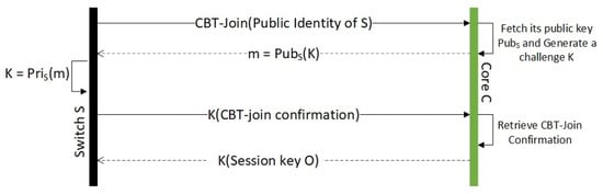 Figure 1. CBT-Join for switches that are one hop away from a core node.
Step 3: Switches That Are More Than One-Hop Away from a Core Node
As before, let S be a switch that wishes to join the CBT-delivery tree.
- S broadcasts a CBT-Join message to every switch connected with S, if it is received by a switch that is not a part of the CBT-delivery tree yet will ignore the message.
- If the message is received by a switch that is already a part of the delivery tree, it will forward to its attached core through the reverse path.
- Let C be the core node that receives the CBT-Join message from S forwarded by . If C receives the forward from multiple switches, it will process only the message with the best cost (shortest hop, least latency, etc.). Messages forwarded through other switches will be ignored. C then follows the same challenge-and-response scheme outlined in Step 2 to authenticate S and add to the delivery tree. The core also sends a copy of the CBT-Join Confirmation message to . Thus, knows that S is authenticated to join the CBT tree. The switch S then creates a reverse pointer to , and creates a forwarding pointer to S.
- As before, if S received multiple challenges from different core nodes, it will process the one with the best cost. For all other core nodes, S will issue CBT-join reset messages.
The message flow diagram outlining this step is given in Figure 2.
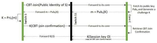
Figure 2.
CBT-Join for switches that are more than one hop away from a core node.
4.1. Tree Maintenance
On-going maintenance of the multicast-tree is one of the important aspects in a multicast communication. Nodes may join and leave the network anytime at their will. In our case, there are two types of nodes in the network:
- Network devices such as switches, routers, and servers: They are expected to be available in the network on a 24/7 basis. They leave the network only when they are down, during maintenance or during the decommissioning process.
- End-host who may join and leave the network any time.
We do not use explicit keep-alive messages to maintain the status of a switch. This is implicitly inferred through physical layer (port connectivity) or link-layer switching activity of a switch. Explicit keep-alive messages consume more bandwidth.
We now discuss the case when a switch S wishes to leave the network.
Case 1: A Switch S Wishes to Leave the Network.
We again spilt the case into two sub cases depending on whether S has children with respect to the CBT delivery tree or not.
Subcase 1.1:S is a leaf node with respect to the CBT delivery tree.
In this case, whenever S leaves the network, no other switch will be affected. To leave the network, S initiates a CBT-leave message, digitally signs it, and forwards it to the core C to which it is associated with. Signing the message digitally will ensure that no rouge switch or a host launch a DoS attack by initiating a CBT-leave message to disrupt the normal operation of the CBT. The core C will in turn multicast CBT-leave ACK containing S’s identity and digitally signed by the core’s private key. The digital signature of the core will ensure that the message originates from C, not from any rouge switch. Every switch in the CBT delivery tree receiving this information will remove S from its state or cache information. In the case of , it will close the forwarding port to S. Thus, in the future, no multicast data packet will be forwarded to S by through port P.
There is no need to refresh the ongoing session key as no switch will forward its multicast data packet to S, including new session key.
The above mechanism works well when S is a leaf node. However, if S has one or more children, they will lose the CBT connectivity whenever S leaves the network. Thus, we follow a different mechanism whenever S has one or more children.
Whenever a host node wishes to leave the network, it will follow the same procedure outlined in Subcase 1.1. Since host nodes are leaves of the CBT, leaving the network will not affect the rest of the network.
Whenever a switch leaves the network, all hosts connected to the switch are forcefully disconnected from the CBT. Since switches leave the network only in case of a power failure, hardware or a link failure or due to maintenance. In this case, the nodes connected to these switches also lose their network connectivity.
In what follows, children means switches and routers (network hardware), but not end-hosts. Subcase 1.2: S has one or more children (switches) with respect to the CBT delivery tree
Before we deal with this case, we present some fundamental theory that will facilitate to handle this case. Let G be a connected graph. A vertex u in G is a cut-vertex, if the removal of u from G makes G a disconnected graph.
Let G be the graph of the underlying topology of the network. If G is a 2-connected graph (the size of the minimum cut-vertex is 2), then there will be at least two vertex disjoint paths between any two vertices of G.
We now return to Subcase 1.2. Let S be the CBT-node that wishes to leave the network, and S has one or more children with respect to the delivery tree. Let C be the core node to which S is connected. Let be the sub-tree of the delivery tree that consists of the reverse path from S to C and all the descendant nodes of S with respect to the delivery tree.
Let be any arbitrary child of S and P be the reverse path from to C through S. Since the underlying topology is a 2-connected graph, there exists another path between and C not containing S. The proof is obvious. If every path between and C passes through S, then the removal of S from the topology will disconnect C and . Thus, S is a cut-vertex of the underlying topology, contradicting the fact that the underlying topology is a 2-connected graph.
Based on the above property, we analyse P and starting from . Let be the first node in (from towards C) that is not in (the sub-tree defined before) and U be the node that precedes in . Such a exists, as is a path between and C not containing S.
We now make an important observation. Since , S leaving the CBT delivery tree will not impact the connectivity of with the CBT delivery tree. By our choice, U is one hop away from . If U establishes connectivity with , then the entire descendants of with respect to the delivery tree T reestablishes connectivity with their core node C through .
Based on the above important observation, we handle Subcase 1.2. The steps are as follows:
- S multicast CBT-intention to leave message to every descendant of S. This message is digitally signed by S to establish the origin of the sender.
- Every descendant of S receiving this message will broadcast a CBT-rejoin message. This message is encrypted with the ongoing session key. Any switch receiving this message will not be rebroadcast. Let K1 be a switch that receives this message. If K1 is also an affected node, K1 will not ignore this message. It will keep in the process queue, until it gets reconnected to the CBT delivery tree.
- Let K be a switch that receives this message from a switch L, and K is not impacted by S leaving (this is known from the fact that K has not received the CBT-intention to leave message from S). Since this message is encrypted using the ongoing session key, there is no need to re-authenticate L. Thus, K creates a forwarding pointer to L; create a CBT-rejoin accept message; and encrypt with the ongoing session key and transmit to L.
- On receiving this message, if L is accepting this message, it will perform the following tasks:
- Create a reverse pointer to K.
- Transmit CBT-rejoin ACK to K to finalize the connection. On receiving the ACK message, K will create a forward pointer to L.
- Multicast to every node in CBT-reconnected message. On hearing this message, S will initiate CBT-leave like in Subcase 1.1.
- If L received CBT-rejoin accept from multiple switches, it will choose the one with the best cost (as defined before). For all other switches, L issues a CBT-reset message.
- L might have received CBT-rejoin from several switches before it reestablished its connectivity with its core node. L will now process their request by issuing them with a CBT-rejoin ACK message; these switches will either connect with L or issue a reset message if they already have established connection.
- As soon as S receives the first CBT-reconnected message from its descendant, it will initiate CBT-leave. This message will be handled similar to sub case 1.1.
We are now left with two cases; the link between S and is broken and S is down due to abrupt power failure.
Case 2: The Link between S and S1 is Broken.
Let be the ancestor for S with respect to the delivery tree. As before, the underlying topology is a 2-connected graph. Thus, we can find an alternative path between S and its core C without passing through (or using the port connected between S and ). We handle this case by slightly varying Subcase 1.2.
As like Subcase 1.2, S will multicast CBT-disconnected message to every descendant of S followed by a CBT-rejoin message. On hearing CBT-disconnected message, every descendant of S, including S, will follow like Subcase 1.2 to reestablish connectivity with the CBT delivery tree.
From the link-layer activities, will also note that either S or the link connecting S and is down. issues CBT-disconnected message on behalf of S to its core node. The core node and will remove its forward pointer to S and wait for it to get reconnected.
Case 3: Switch S is Down Due to Abrupt Failure
Let , , ⋯, be the children of S. As soon as S is down, these children will notice it from the link-layer activities with S. As like Case 2, these switches multicast CBT-disconnected message to every descendant of them followed by CBT-rejoin message. Since the underlying topology is 2-connected, they will get reconnected to the CBT delivery tree. Similar to Case 2, will inform its core switch and remove its forward pointer to S.
We listed all possible CBT-messages in Appendix A.
4.2. Security Analysis
In this subsection, we analyse how robust our algorithm is in terms of security requirements.
4.2.1. Impersonation Attack
There are two types of impersonation attacks possible in a network. In the first case, a malicious device (switch, router, or a host) without an active connection to the network may try to join the network using someone’s identity. In the second case, a legitimate device may already join the network and pretend to be someone else.
The first case is not possible. In order to decrypt the challenge, a node must need its private key. A node impersonating someone else will not have the knowledge of the private key of the impersonating node.
In the latter case, if M wishes to impersonate L, it needs to have the knowledge of L’s private key in order to digitally sign the messages. Thus, the second case is also impossible in our proposal.
4.2.2. Compromised Key
Whenever a key of a particular host or a device is compromised (due to a number of various reasons, which is beyond the scope of this paper), the core will generate a new pair of public and private keys for the compromised node. In our proposed model, we are not revoking the identity of the compromised node. Using the new hash polynomial, every end-host will identify the compromised host through its newly generated keys; thus, the old keys are naturally removed from the system.
4.2.3. Replay Attack
Whenever a device is decommissioned, its profile is removed from the entire corporate database. However, in a large organization, host profiles are stored in multiple locations and may be difficult to remove all at the same time. This deficiency may be exploited by the attackers. They may reconnect the device to the corporate network and launch a replay attack using its old profile.
In our proposed system, as soon as a new system is installed, we create a new set of public and private key pairs, without changing its publicly known identity. Our system will also distribute the new hash-polynomial securely to all nodes. Whenever a decommissioned system uses its publicly known identity, only its new keys are used by other hosts. Whenever it initiates a CBT-join, the response to this CBT-join by means of a challenge will be encrypted using its new public-key. Since the decommissioned node has no knowledge of its new private key, it may not be able to join the network using its old profile. Any unsolicited message sent by the decommissioned node will be ignored, as its digital signature may not be valid.
4.2.4. Single Point Failure
In the case of a PKI based system, the certificate authority is a single-point failure. In our case, the certificate authority is not needed once the system is created. Since we use k-threshold cryptography as the underlying cryptosystem, a new set of keys can be generated through collaborating with k-hosts in the network. Thus, the job of the CA is distributed among k-nodes in the network. Hence, it is impossible to bring the network down by attacking a single host or a server in the network.
5. Conclusions and Future Directions
In this paper, we proposed the use of pseudo-identity based encryption along with core-based tree architecture to create a secure multicast delivery mechanism in a corporate LAN. As we discussed in the previous section, our proposed architecture is immune to a number of security attacks that are possible through the use of the existing methods. Our system can be used efficiently for the following applications:
- The secure multicast established through our proposed system can be used to deploy OS updates, patches, and device updates, including the update of new configuration. Since the messages are digitally signed, only the legitimate server can perform this operation.
- Routing protocols like RIPv2 and OSPF can effectively use this tree to send their route updates to other routers in the network.
- In our earlier paper [1], we proposed PrECast architecture to provide an efficient crypto-free solution to a number of LAN based attacks that are due to IPv4 broadcasting. PrECast assumes the existence of a secure multicast tree in the LAN. In this paper, we propose a secure multicast mechanism to close the gap.
Author Contributions
Conceptualization, writing—original draft preparation, P.V.; investigation, D.H.; supervision, writing—review and editing, E.P.
Funding
This research received no external funding.
Conflicts of Interest
The authors declare no conflicts of interest.
Appendix A. List of CBT Messages
| CBT-Join | Message sent by a host in order to join the CBT tree |
| CBT-join confirmation | Message sent by a core CBT node in response to CBT-Join. |
| CBT-join reset | Message to deny a CBT-Join confirmation, in case it is received from multiple core nodes. |
| CBT-leave | A CBT node decided to leave the network. |
| CBT-intention to leave | A CBT non-leaf node decided to leave the network. |
| CBT-rejoin | A CBT node trying to change its point of attachment to its tree. |
| CBT-rejoin accept | A new point of attachment has accepted the request |
| CBT-reconnected | CBT node informs other nodes that it changed its point of attachment. |
| CBT-disconnected | Whenever a node lost its CBT connectivity due to link or point of attachment failure. |
References
- Hanna, D.; Veeraraghavan, P.; Pardede, E. PrECast: An Efficient Crypto-Free Solution for Broadcast-Based Attacks in IPv4 Networks. Electronics 2018, 7, 65. [Google Scholar] [CrossRef]
- Loveless, J.; Blair, R.; Durai, A. IPMulticast Vol 1: Cisco IP Multicast Networking; Cisco Press: Indianapolis, IN, USA, 2016. [Google Scholar]
- Doyle, J.; Carroll, J.D. Routing TCP/IP; Cisco Press: Indianapolis, IN, USA, 2012; Volume 1. [Google Scholar]
- Shamir, A. Identity-based cryptosystems and signature schemes. In Workshop on the Theory and Application of Cryptographic Techniques; Springer: Berlin/Heidelberg, Germany, 1984; pp. 47–53. [Google Scholar]
- Boneh, D.; Franklin, M. Identity-based encryption from the weil pairing. In Proceedings of the Annual International Cryptology Conference, Santa Barbara, CA, USA, 19–23 August 2001; Springer: Berlin/Heidelberg, Germany, 2001; pp. 213–229. [Google Scholar]
- Cocks, C. An identity-based encryption scheme based on quadratic residues. In Proceedings of the IMA International Conference on Cryptography and Coding, Cirencester, UK, 17–19 December 2001; Springer: Berlin/Heidelberg, Germany, 2001; Volume 2260, pp. 360–363. [Google Scholar]
- Chatterjee, S.; Sarkar, P. Identity Based Encryption; Springer: New York, NY, USA, 2011. [Google Scholar]
- Veeraraghavan, P. Pseudo-identity based encryption and its application in mobile ad hoc networks. In Proceedings of the 2011 IEEE 10th Malaysia International Conference on Communications, Kota Kinabalu, Sabah, Malaysia, 2–5 October 2011. [Google Scholar]
- Shamir, A. How to share a secret. Commun. ACM 1979, 22, 612–613. [Google Scholar] [CrossRef]
- Simonite, T. To Keep Passwords Safe from Hackers, Just Break Them into Bits. Available online: https://www.technologyreview.com/s/429498/to-keep-passwords-safe-from-hackers-just-break-them-into-bits/ (accessed on 19 September 2019).
- Oppenheimer, P. Top-Down Network Design; Cisco Press: Indianapolis, IN, USA, 2010. [Google Scholar]
- Ballardie, A.J.; Francis, P.F.; Crowcroft, J. Core Based Trees. ACM SIGCOMM Comput. Commun. Rev. 1993, 23, 85–95. [Google Scholar] [CrossRef]
- Donahue, G.A. Network Warrior, 2nd ed.; O’Reilly Press: New York, NY, USA, 2011. [Google Scholar]
© 2019 by the authors. Licensee MDPI, Basel, Switzerland. This article is an open access article distributed under the terms and conditions of the Creative Commons Attribution (CC BY) license (http://creativecommons.org/licenses/by/4.0/).