Abstract
Photovoltaic (PV) modules experience some partial shading conditions (PSC) due to some various factors. In that kind of a condition, a few maximum power points (MPPs) possibly appear on the power-voltage (P-V) curve, which increases the tracking difficulties. It is known that maximum power point tracking (MPPT) may not be realized by hill climbing (HC) based conventional MPPT algorithms under PSCs. In this context, this paper presents a novel micro converter based algorithm that was developed by using P-V characteristics of PV modules. Unlike voltage or duty ratio scanning techniques, this paper introduces a new deciding method to determine the correct global MPP (GMPP) region. For this, the proposed method uses some duty ratios that were calculated corresponding to each MPP region. Thus, the initialization of duty ratio is done properly, which results in high tracking speed and accurate tracking of the GMPP. The other advantages of the proposed algorithm are structural simplicity, less computational burden, and ease of implementation with a basic microcontroller. The simulation results show that this algorithm has fast tracking capability and it manages to track GMPP for PSCs correctly, since it includes an artificial scanning procedure. Single ended primary inductance converter (SEPIC) is built in order to validate the proposed global maximum power point tracking (GMPPT) algorithm. The performance of the proposed GMPPT technique is verified by experimental studies. The results show that the proposed GMPPT technique is fast by up to five times than an adaptive full scanning strategy and improved IC algorithm. Furthermore, the proposed algorithm can be commercially used in micro converters, since it is compatible with small number of bypass diodes in a module.
1. Introduction
Solar energy is one of the renewable energy sources and it has been used extensively in solar power generation systems [1]. Photovoltaic (PV) modules are the main components of these systems and they are non-linear direct current (DC) power sources. The available power of the modules depends on the amount and distribution of solar irradiance. If the entire surface of a module is exposed to the same solar irradiance, its P-V curve only has a single maximum power point (MPP). This can be defined as a uniform irradiance condition (UIC). In that kind of a condition, maximum power point tracking (MPPT) can be accomplished by conventional algorithms, such as perturb and observe (P&O) [2], incremental conductance (IC) [3], fractional short circuit current (SCC) [4], and fractional open circuit voltage (OCV) algorithms in this condition [5]. However, in a roof type and/or building integrated PV (BIPV) system, they probably do not extract maximum power in partial shading conditions (PSCs) due to the complexity of P-V curves and/or wrong decision when the first MPP is reached. Therefore, several algorithms and methods have been proposed in order to realize global MPPT (GMPPT [6,7,8,9,10,11,12,13,14,15,16,17,18,19,20,21,22,23,24,25,26,27,28].
Studies in literature that were conducted for GMPPT can be divided into two groups. General feature of the first group is based on the characteristic curves of PV modules. A two stage MPPT control algorithm that is based on instant measurement of OCV and SCC of PV module is proposed in [6]. In the first stage, the vicinity of GMPP is aimed to be reached by using the load line approach. The derivative of power with respect to voltage is used in the second stage, afterwards. A similar strategy has been proposed in [7]. Tey et al. proposed a 0.8 VOC model that was based on the GMPPT technique with a modified IC algorithm. Even if it shows satisfactory performance, the tracking speed is small due to the HC strategy in the first stage of their algorithm. Fibonacci search algorithm is used for tracking GMPP in a PV system in [8]. An MPPT algorithm that is based on PV characteristics has been developed by conducting extensive simulation studies in [9]. Dividing rectangles (DIRECT) algorithm has been used in another study for searching the GMPP by defining a P-V curve as a Lipschitz function [10]. The area dividing strategy and potentially optimal interval for tracking parameters are defined by using PV parameters, which results in high system dependency. A voltage scanning based MPPT approach that operates on the load characteristic curve is implemented. It is claimed that the voltage value at MPP is higher than a reference value that is set by the authors in [11]. According to Ji et al., when PSC is detected, vicinity of GMPP can be easily tracked by using a linear function [12]. However, some coefficients have to be calculated, so as to detect PSC, which increases the system dependency of this study. A PV characteristic that is based on the MPPT algorithm has been proposed in [13]. An analytical condition is introduced for PSC detection in this study, but there is a disadvantage for this algorithm in that it is highly system dependent.
The algorithm used in [14] takes the number of bypass diodes and possible voltage bands that appeared in the P-V curve into consideration. Voltage band is to be determined for GMPPT. This power is estimated by polynomial fitting obtained from a few voltage samples taken for certain conditions in [15]. A complete scanning is avoided in this way. A field programmable gate array (FPGA) based MPPT method that uses a charging of the capacitor connected to the output of PV module is used. The voltage and current of capacitor are stored and GMPP is determined during the charging. Independence of the system parameters and configuration types are the prominent feature of this approach. However, the periodical charging of this capacitor leads to a disconnection between the PV array and load [16]. The segmentation search method based on PV characteristics [17], working mechanism of bypass diodes [18], and an algorithm using the relationship between load line and I-V curve with trigonometric rule is presented to increase response time under changing environmental and load conditions [19]. On the other hand, in another group of studies, some novel methods, like artificial neural network (ANN) [20], fuzzy logic [21], particle swarm optimization (PSO) [22], differential evolution algorithm [23], and full scanning based and evolutionary algorithms (such as ant colony optimization and genetic algorithm) have been proposed in [24,25,26,27,28].
A smart PV module approach has been very popular, especially in a small PV system, since it performs its own MPPT and a high tracking efficiency is obtained [23,28]. It will be not surprising that MPPT can be panel dependent in the future. Tracking efficiencies and tracking speed decreases in PSC, which results in the unreliable operation in PV systems. To prevent this unreliable situation, a novel GMPPT algorithm that is based on PV characteristics and duty ratio initialization is proposed for micro converter/DC power optimizer applications in this paper. Partial shading deciding approach to determine the correct MPP region on the P-V curve is provided by measuring included bypass diode voltages in a module. This approach employs some duty ratios that are calculated by extensive simulations carried out for the P-V curves of the PV modules. As known, this approach is feasible for micro converters, since a PV module has limited bypass diodes included. A single ended primary inductance converter (SEPIC) is used as the power processing unit in order to validate the performance of the proposed algorithm. The remains of this paper continue, as follows: The current-voltage (I-V) and P-V curves of typical PV modules for UIC and PSCs are described in Section 2. Furthermore, the operation of the bypass diodes in a module is explained in this section. The proposed algorithm is extensively explained in Section 3. The results of the simulation and experimental studies that verify the proposed methodology are released in Section 4 and Section 5, respectively. The contributions of this study are highlighted as conclusions in the last section.
2. PV Characteristic in PSC
The smallest piece of PV modules is a solar cell, whose power depends on the value of solar irradiance and temperature. Solar cells are connected in series to each other, forming modules that have exponential I-V and P-V characteristics under UICs. There is only single MPP on the I-V curve in this condition as presented in Figure 1a. If a module is exposed to a PSC and if there are no bypass diodes included, it generates power depending on the intensity of shadowing, which substantially reduces the available power, as presented in Figure 1b. In this condition, partially shaded solar cells behave as a load and consume some energy, instead of generating [12]. If the amount of the energy consumed increases much, it is possible that a hotspot problem occurs and PV modules are destroyed because of excessive thermal stresses. Therefore, bypass diodes are used for protecting modules. A number of these diodes are generally determined by the rated power of the modules. Generally, PV modules do not have more than three bypass diodes, except for any specific products [29]. In Figure 1 c, the module has three bypass diodes, which may lead to three MPPs on the P-V curve. The maximum power is bigger for the case with bypass diodes than that for the case without them, as shown in Figure 1b. Furthermore, the P-V curve becomes more complex than the one under UICs.
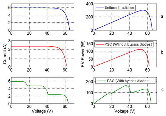
Figure 1.
Current-voltage (I-V) and power-voltage (P-V) curves of a module (a) Uniform irradiance; (b) partial shading condition (PSC) without bypass diodes; and, (c) PSC with bypass diodes.
When a PSC occurs, the I-V curve of a PV module becomes similar to a ladder, as shown in Figure 2. For example, a module has three series connected cell groups and all of the groups have their own bypass diodes. I-V curve of this module is given in Figure 2. It is seen that one of the shaded cell groups of the module starts to generate power, when current of the module is equal to the one of the shaded cell groups (PV-2). First, PV-1, which is the highest irradiated cell group, generates power alone until the current of PV-2 becomes equal to a current of the module, as shown in Figure 2. The voltage of PV-2 is negative and it behaves as a load before it starts to generate power. It is worth noting that, when shaded part of the module starts to generate power, its voltage gets positive value. That is, in each stair of the ladder, the voltage of PV module increases, since each cell group starts to generate power one by one, as presented in Figure 2.
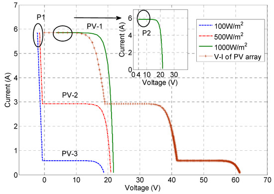
Figure 2.
Each I-V curves of cell groups in a module.
Partial shading is the most problematic condition for PV modules, which not only reduces the available power of the modules, but also increases the complexity of P-V and I-V curve of them. In other words, partial shading causes an increment in the number of MPPs on the P-V curve, which makes MPPT difficult when compared with the complexity level of UICs. Besides that, HC algorithms may not able to find GMPP [9], since they stop tracking when the first MPP is tracked. However, the exact maximum power may not be this one. The entire P-V curve should be scanned in order to find the GMPP by using these algorithms. However, convergence time increases, deteriorating MPPT quality. In the proposed methodology, a new duty ratio initialization based algorithm is introduced with the help of the general characteristics of PV modules.
3. Materials and Methodology
Researchers have developed GMPPT algorithms by proposing a mathematical equation or defining an index before, so as to detect PSC [7,8,9,10]. Generally, they define an equation and check it in a certain time interval. Subsequently, a PSC block starts to be operated for finding the vicinity of MPP correctly. Most of them use an HC based algorithm, finally. The main drawbacks of these studies are the increase in stage numbers, computational burden, dependency of system parameters, and inclusion of different algorithms for uniform irradiance and PSCs. On the other hand, in this study, significant clues in characteristic curves of PV modules are employed in the context of the proposed GMPPT algorithm, which is explained in the next sections.
In recent years, hardware based approaches have been aimed to be developed, even if MPPT is mostly accepted as a software based operation. In a classical PV system, a centralized power converter unit makes the conversion and controlling of entire power. For example, there are several PV modules connected in series and/or parallel, forming a PV array. This array is connected to a centralized converter. Although this type of system has some advantages in terms of ease of implementation and cost, the available power might not be extracted in some cases, like shading and/or malfunction of a part of the system, which leads to decrease the unreliability of such these systems. On the other hand, the micro converter structure introduces new advantages, such as high reliability as compared with the centralized one, high efficiency, easy maintenance options, and ease of MPPT algorithm, which is the main focus of this study. A PV system is given in Figure 3; all PV modules operate independently and they have their own micro converters that supply to the load/grid/battery. The manufacturing of the junction boxes and PV modules are commercially independent from each other. Most of the time, junction boxes have three bypass diodes that led to three potential MPP regions to track. Since the performance of the proposed algorithm depends on the number of bypass diodes and the micro converter structure requires one module, it means that the proposed GMPPT algorithm is suitable in micro converter applications.
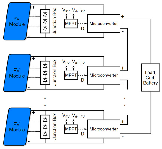
Figure 3.
PV modules with several micro converters.
3.1. Preliminary Analyses for Power-Voltage Curve under PSCs
PV modules have multiple MPPs when they are exposed to different solar irradiance. The maximum value of the number of MPPs is equal to the number of bypass diodes in a module. Assume that a module has three series connected cell groups that have their own bypass diodes. Several shading scenarios are generated for simulations in order to characterize P-V curves of a module. In order to determine the number of shading scenarios, the increment of solar irradiance, ∆QINC, is set. This parameter can be accepted as 100 W/m2. Value of solar irradiance varies from 100 W/m2 to 1000 W/m2 [30]. The number of shading cases is calculated for the maximum number of MPPs, as in (1).
In (1), c is the number of shadowing conditions, m is the ratio of the maximum irradiance value and the increment of solar irradiance (m = 1000 W/m2/100 W/m2 = 10), and n is the number of bypass diodes in a module. Assume that a module combined with three bypass diodes can receive three different solar irradiances. Thus, there are three MPP regions on the P-V curve as a result. In all of the shading cases, the P-V curves of the module are presented in Figure 4. It is clear that MPPs are clustered in certain MPP regions. These regions are always vicinity of 80% of the OCV of each cell group [9,10,13,22]. The proposed algorithm aims to firstly reach the vicinity of the correct MPP region. So as to decide to this region and not to diverge to local MPP, average the equivalent resistance (ER) of the PV module/array at MPP is calculated, as in (2), for the purpose of providing proper duty ratio initialization.
where RPVavg is the average ER of PV module and Vmpp and Impp in (2) are the voltage and current of the module at MPP, respectively. Pmpp is the maximum power value of the module. According to the shading conditions, average ERs of PV module at all MPPs regions are calculated. Subsequently, the values of duty ratios are calculated for them, as given in (3), for a buck-boost converter topology [31].
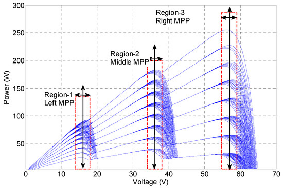
Figure 4.
Typical P-V curves of the module under 120 shading cases.
Rload is the value of load resistance. D is the duty ratio of the pulse width modulation signal. After the calculation of the duty ratios, necessary analyzes for the searching of the GMPP process is completed. Figure 5 shows the two P-V curves for the shading with maximum irradiance (minimum RPV) and minimum irradiance (maximum RPV) conditions. With the help of an average value of the duty ratio calculated for one MPP region, it is guaranteed that the operating point of a PV module stays in the rectangles that are given in Figure 5.
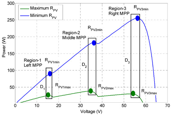
Figure 5.
Minimum and maximum equivalent resistance (ER) of photovoltaic (PV) module at maximum power points (MPPs).
3.2. Duty Ratio and Load Characteristic
It is important to know the variation of the duty ratio interval and the value of load resistance in the proposed approach. The value of this interval should be analyzed, so as to prove the effectiveness of the proposed algorithm. It is clear that, for buck-boost converter topology, maximum value of the duty ratio range is roughly 40%, as can be seen in Figure 6. Although this range increases by a specific value of load resistance, it slightly decreases from this value of resistance. If entire of the P-V curve is scanned normally, duty ratio has to be varied from 0% to 100%, theoretically. However, investigating the variations of duty ratio by load resistance value provides a limited region of duty ratio. Therefore, searching of GMPP becomes easier than entire of the P-V curve scanning. On the other hand, the value of duty ratio changes by the value of load resistance, which should be calculated, before MPPT starts. Figure 6 shows the relationship between duty ratio and value of load resistance. In this figure, three curves represent the duty ratio variations for three MPP regions. These relationships are obtained by using (3) explained in the previous subsection.
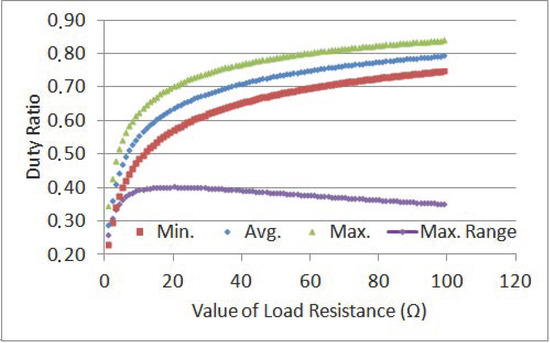
Figure 6.
Variation of duty ratio (minimum, averaged, and maximum) and load resistance.
3.3. Proposed Algorithm
This novel GMPPT algorithm is developed by using the I-V and P-V characteristics of a PV module and the simple calculations that are explained before. An electrical circuit of the proposed MPPT system that consists of SEPIC, sensing circuits (voltage divider and current transducer), some electronic components for PSC detection, and MPPT block are presented in Figure 7. The first consideration is to check whether PV module receives different irradiances or not in this algorithm. In order to decide PSC, NPN type transistors, T1, T2, and T3 are switched on by the MPPT controller. Subsequently, the value of Vd1, Vd2, and Vd3 are evaluated in the control unit. In a PSC, the bypass diodes of the shaded cell groups have negative voltages at the beginning of the I-V curve, as presented in Figure 2 (illustrated in P1 circle). This can be formulated, as in (4).
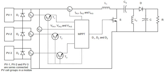
Figure 7.
Circuit of the proposed maximum power point tracking (MPPT) system and micro converter.
ISC is the SCC of the PV module, Vn is the voltage of maximum irradiated cell groups and the other voltages (Vd1, Vd2, ..., Vdn−1) correspond to the voltage of the partially shaded cell groups, here. In order to satisfy (4), the value of duty ratio should be as much as big. In this condition, the current of PV module is roughly equal to SCC (IPV ≈ ISC). For a SEPIC, the ER of the PV module can be written, as in (5) [30,32].
If the current of the module is roughly equal to the SCC (IPV ≈ ISC), the voltage of PV modules is approximately zero. When the ratio of the voltage of the module and current of it is used instead of ER of PV module in (5), the formulation shown in (6) is obtained.
Theoretically, if the duty ratio equals to one (100%), (6) becomes mathematically zero. Therefore, the maximum value of the duty ratio is set to a maximum value (80–90% of duty ratio). For this value of duty ratio, the voltage of a PV module is roughly zero. As presented in Figure 8a, the voltages of the bypass diodes are checked, so as to determine PSC. If one of the bypass diodes has negative voltage, the duty ratios values are set as d1, d2, and d3 for three MPP regions. The P-V curves of PV-1, PV-2, and PV-3 are scanned by operating all the micro converters with a duty ratio of d1, d2, and d3. As illustrated in Figure 8b, for each duty ratios, the power of the module is calculated by using the voltage and current of it in each sample time. The maximum value of the power is stored (P1m for d1, P2m for d2, and P3m for d3) as a result of artificial scanning of power, for three MPP regions. Afterwards, the stage of power-duty (P-D) conversion starts. In fact, this stage contains a basic power comparison in order to set the initial value of duty ratio, which corresponds to the maximum power calculated. It is initiated for reaching the vicinity of the GMPP. Finally, P&O algorithm is used. When P&O starts, power change (p) is continuously checked. If this change is bigger than the threshold value of power (pthr), which should be calculated by the step size of duty ratio value and its corresponding power change, PSC is checked again and the algorithm steps shown in Figure 8a are operated. If PSC does not occur, it may mean changes in irradiance or the value of load resistance. However, since this study focuses the PSC and its difficulties in GMPPT, this is not taken into consideration in this study.
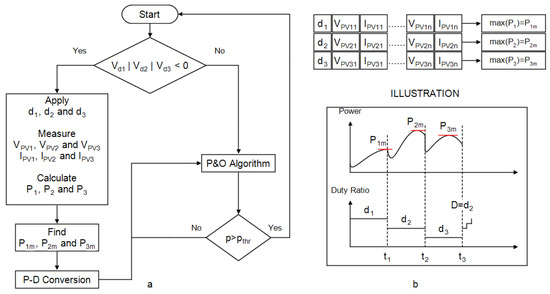
Figure 8.
(a) Flowchart of the proposed algorithm; (b) Illustration of the algorithm operation.
4. Performance of the Proposed Algorithm
A 300W powered SEPIC has been modelled in MATLAB/Simulink in order to demonstrate the performance of the proposed algorithm. Table 1 lists some specifications of the PV module for standard test conditions (STC) and the components used in the SEPIC prototype. Three series of connected sub-modules are the configuration type of the module. Each of the cell groups has its own bypass diode. Therefore, there are possibly three MPPs on the P-V curve. SEPIC is chosen as the power processing unit due to the high MPPT capability, one of the buck-boost converter having positive output voltage, and the feature of continuous PV current [31].

Table 1.
Specifications of the PV module and single ended primary inductance converter (SEPIC).
4.1. Simulation Results
Five simulation scenarios are created to verify the performance of the methodology that is elaborately explained in Section 3. Case conditions, value of load resistance, the initial value of duty ratio, tracking efficiencies at MPP, and convergence time are listed in Table 2. Furthermore, some parameters that are related to simulated conditions are specified.
Table 2.
Simulation results and conditions.
In the first case, the PV module receives three different amounts of solar irradiance. First, the maximum value of the duty ratio (95%) is applied to the SEPIC to detect whether PSC occurs. It is clear in Figure 9d that, PV module is operated at SCC condition since the voltage of a PV module is roughly zero, as is obviously observed in Figure 9a. Then, three duty ratios (d1, d2, and d3) are applied to the SEPIC, so as to determine the correct MPP region (GMPP region), as shown in Figure 9c. Since maximum power is obtained when D = d1, the value of d1 is set as the initial value at t = 60 milliseconds (ms). Finally, the P&O algorithm is used and GMPPT is realized. The tracking time is observed as roughly 86 ms. In this case, two of the cell groups have negative voltages at steady state operation, which is observed between t = 86 ms and t = 120 ms shown in Figure 9f. Operation of bypass diode in a shadowing condition listed as a Case 1 is illustrated in Figure 10. It is clear that the bypass diodes of the shaded cell groups (PV-1 and PV-2) have negative forward voltage drop (VF), which leads to a decrease in the voltage of the module. The current generated by the most irradiated module flow through these diodes. The significant amount of power is lost in bypass diodes of these cell groups since forward voltage drop and forward current take maximum value. Tracking efficiency is very low when compared with the other cases due to the power losses.
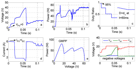
Figure 9.
Case 1 (a) Voltage; (b) Power; (c) Duty Ratio; (d) Current; (e) P-V curve; and, (f) Voltage of bypass diode.
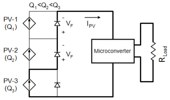
Figure 10.
Operation of bypass diodes in a PSC.
In the second case, there are two MPP regions due to two different levels of solar irradiances. The initial duty ratio is set to maximum value for providing operation at the leftmost region in the I-V curve seen in Figure 2 in order to detect whether a PSC occurs or not. When it is observed that the PV module is exposed to different irradiance amounts, the duty ratios calculated are applied to the SEPIC. According to the power values for each of the duty ratios, the initial value of the duty ratio is set for reaching the vicinity of the GMPP. Convergence to MPP is ensured in a few milliseconds in this case, as can be observed in Figure 11a. On the other hand, the bypass diodes of the shaded cell groups have not negative voltages at steady state operation (at MPP), since GMPP is around the rightmost MPP region in this case. During this operation, tracking efficiency, which is the ratio of tracked and theoretical power, is 99.4%. Tracking time is 105 ms for this case.
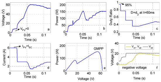
Figure 11.
Case 2 (a) Voltage; (b) Power; (c) Duty Ratio; (d) Current; (e) P-V curve; and, (f) Voltage of bypass diode.
Since the step size of duty ratio is large for far away from the MPP and small step size in the vicinity of MPP region, the proposed algorithm operates as a variable step size algorithm. Besides that, it is proper to be used in a UICs. To observe its performance by comparing one of the classical algorithms, P&O, the standard test condition is used in the third case. It is shown that the algorithm proposed for PSC can be also used in UICs with better performance. For this comparison, the step size of the duty ratio in P&O algorithm and proposed algorithm is selected as 0.5%. The initial value of duty ratio is 10% in the P&O algorithm. The results of this case are presented in Figure 12. It is clear that the proposed algorithm has better performance than P&O in terms of convergence time. By using the proposed approach it converges to MPP at t = 65 ms; however, by using P&O, it converges at t = 110 ms.
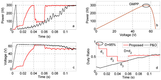
Figure 12.
Case 3 (a) Voltage; (b) Power; (c) Duty Ratio; and, (d) Current.
In the last two cases, the performance of the algorithm is observed for different load resistances. The shading pattern is 400-500-1000 W/m2. It is clear in Figure 13d that, although values of duty ratios are different due to the different load resistances, the response time of these two cases is very close to each other. However, it does not matter for GMPPT. In these two cases, the tracking of GMPP is realized, as expected. As is clear in Figure 13a, the power of the module is the highest between t = 40 ms and t = 60 ms. Therefore, d3 is set as the initial value of the duty ratio for reaching the GMPP as much as fast. Thanks to this result, it is verified that the proposed algorithm can manage the GMPPT in different load resistances. On the other hand, steady state performances are also roughly the same. This can be understood by observing the power value at MPP.
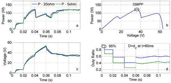
Figure 13.
Case 4 and Case 5 (a) Voltage; (b) Power; (c) Duty Ratio; and, (d) Current.
4.2. Experimental Results
The performance of the proposed GMPPT algorithm is experimentally validated. The PV simulator, which generates a proper P-V profile, has been used instead of a PV module in experiments. Before producing P-V profiles, some information of the photovoltaic panel given in the catalogs under standard test conditions is entered into the software. Table 1 lists the main specifications of the PV module. Thanks to the PV simulator, the desired irradiation values can be adjusted to the interface program of the simulator and different shading scenarios have been produced. A SEPIC is implemented to process power with the proposed algorithm. In Figure 14, the converter circuit, in which the performance of the algorithm is verified, is shown. Coupled inductor structure is used in order to reduce the cost of inductance. In this way, the inductance value was reduced to half. The prototype built consists of SEPIC, MOSFET driver circuit, and a power source, including +5 V DC and +15 V DC. IR2118 has been used to drive MOSFET in the SEPIC, an integrated circuit. Furthermore, a low cost and easy to find eight-bit microcontroller has been chosen for PWM function, ADC, and GMPPT algorithm. PV current is sensed by a current transducer and the voltage of PV source is sensed by a basic voltage divider circuit.
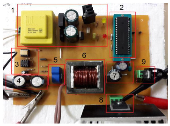
Figure 14.
Prototype of the MPPT converter.
Two PSCs are generated through a PV simulator. In the first PSC, the values of solar irradiances are 200 W/m2, 400 W/m2, and 600 W/m2. For these radiation values, there are three maximum power points in the P-V curve, two of which are local maximum and one is GMPP. This PSC scenario can be evaluated as an extreme case, since the number of MPPs is up to the number of bypass diodes. It is as if a panel of three sub-modules is exposed to different radiation from all sub-modules. In the other shading scenario, the P-V curve is obtained for two MPP states. Values of irradiances are 300 W/m2, 400 W/m2, and 400 W/m2. In this case, two of the submodules receive the same irradiance (400 W/m2) and another submodule receives 300 W/m2.
Experimental studies were carried out to determine the performance of the proposed algorithm and to show its superiority over some other methods. Resistive load is connected to the output of the SEPIC. Two different GMPPT techniques are used for performance comparison. The first one is an optimized and adaptive scanning technique [28], which is based on a scanning of the P-V curve in a limited interval. However, the tracking of MPP cannot be guaranteed in extreme shading cases. The second approach is a modified IC with 0.8 VOC model [7]. The main handicap of this approach is that the first MPP requires multi-step and unnecessary scans.
In the first case, the P-V curve has three maxima, since irradiance profiles consist of three different irradiance levels. Figure 15 gives the I-V and P-V curve of this shading scenario. In this case, the maximum value of power is 90.71 W as indicated in the lower right corner of this figure. Experimental results show that the proposed GMPPT algorithm tracks the GMPP in about 250 ms. Power variation seen in Figure 16a verifies this result. On the other hand, improved IC algorithm completes the GMPPT in a 550 ms, as can be understood from Figure 16b. The last experiment result of the first PSC scenario is observed in Figure 16c. By using the technique in [28], the P-V curve has been scanned in a limited range. However, GMPP is tracked in a second and this time is five times more than the proposed GMPPT algorithm. The P-V curve that is given in Figure 15 is clearly visible on the oscilloscope screen that is presented in Figure 16c.
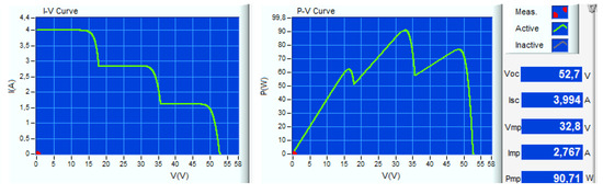
Figure 15.
I-V and P-V curve generated by a PV simulator for the first PSC (200–400–600 W/m2).
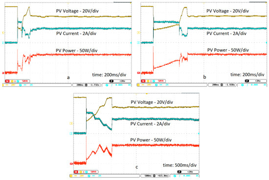
Figure 16.
The results of the first PSC (a) Proposed algorithm; (b) Method in [7]; and, (c) Method in [28].
In the second shading conditions, a PV module appears to be exposed to 300 W/m2, 400 W/m2, and 400 W/m2 irradiation. As two different irradiance values are applied to the PV model, two MPPs occur in the P-V curve, as seen in Figure 17. Maximum power value is calculated as 97.78 W for the second shading conditions. The experimental results show that proposed GMPPT technique has realized the fastest tracking compared with the technique proposed in [7] and [28]. The tracking time is 200 ms, 1s and 1s for the proposed technique, algorithm in [7], and an adaptive scanning procedure [28], respectively. Experimental results of these techniques are presented in Figure 18a–c. It is clear that the proposed GMPPT algorithm eliminates the blind scan and provides a fast MPPT operation under PSCs.
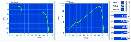
Figure 17.
I-V and P-V curve generated by a PV simulator for the second PSC (300–400–400 W/m2).
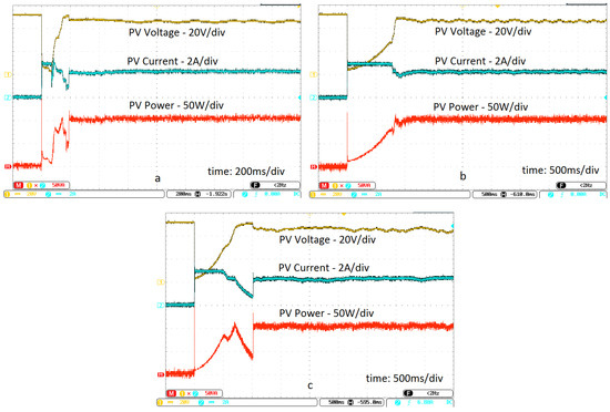
Figure 18.
The results of the second PSC (a) Proposed algorithm; (b) Method in [7]; and, (c) Method in [28].
4.3. Evaluation of the Proposed Algorithm
The proposed algorithm has many advantages in terms of simplicity, requirement of less information about system, applicability due to the structural simplicity, and capability of GMPPT in shading conditions. As presented in Figure 8a, there are two decision blocks and four process blocks as part of the method. If change of power is higher than a predetermined value, the PSC block is activated. Accordingly, the periodical deactivation of the PV system is prevented.
In the proposed algorithm, the number of bypass diodes has to be known before beginning of MPPT operation. A condition that is proposed in this study should be provided in order to detect partial shading. That is, PV module has to be operated at IPV ≈ ISC. For this, the value of the duty ratio is set to its maximum value. Subsequently, the voltage values of the bypass diodes are checked at this condition. If one of them has a negative voltage at IPV ≈ ISC, it means of partial shading. On the other hand, a new search approach is introduced as a result of investigating the relationship between the ER of the PV module at MPP and load characteristic. With this approach, it is obtained that the maximum value of duty ratio interval is 40%, as illustrated in Figure 19. Therefore, a significant reduction in the duty ratio interval is provided. However, some duty ratios whose values are in determined duty ratio interval are applied to the SEPIC one by one instead of scanning of 40% of the duty ratio. As the maximum value of the power is stored for each duty ratios, it is guaranteed to track GMPP for all shadowing conditions.
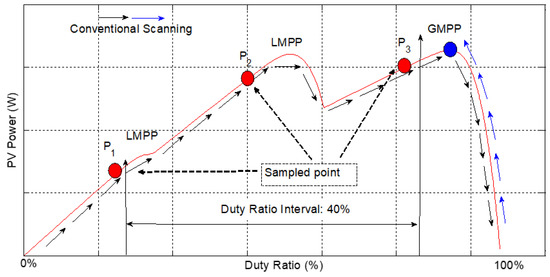
Figure 19.
Duty ratio scanning approaches.
The proposed algorithm can be summarized by a typical operation, as in Figure 20. It can be said that between t = 0 ms and t = 5 ms, whether shading occurs is determined, as a result of applying of the maximum value of the duty ratio (95%). In this condition, the voltage of the PV array is roughly zero, which leads to SCC condition. Subsequently, three duty ratios calculated before are set and PWM are adjusted to these duty ratio values. It is provided that input voltage (PV source) of SEPIC is efficiently scanned from the left MPP region to right MPP region. According to the power generated, the initial value of the duty ratio is determined. Afterwards, P&O algorithm is started to continue GMPPT realization, finally. Figure 20 presents a shading case and all stages of the proposed algorithm can be observed through the results.
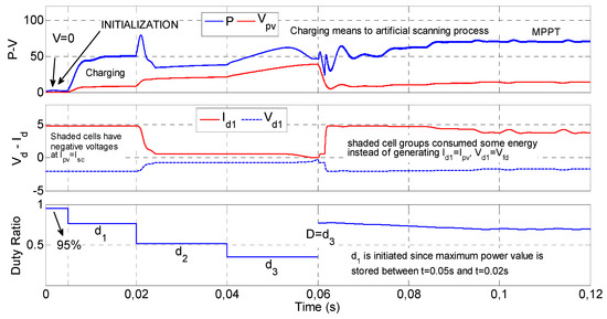
Figure 20.
Summary of the proposed algorithm shown in a PSC operations.
5. Conclusions
Due to the nonlinear characteristics of PV modules and the PSC, extracting maximum power from them becomes complex and difficult for MPPT systems. In this study, a novel micro converter based GMPPT algorithm, which uses some calculated duty ratios in certain and limited interval, is introduced by using the relationship between ER of PV module and the load value.
Simulation and experimental results show that proposed algorithm manages the tracking GMPP under PSCs. The novelties, contributions, and limitations of this algorithm can be summarized, as follows:
- Voltage values of the bypass diodes are checked in order to detect partial shading. If one of the bypass diodes has a negative voltage value, it can be understood that partial shading occurs. However, the voltages of bypass diodes have to be measured under a specified condition. If the maximum value of duty ratio is set to its maximum value, the current of the module is equal to SCC of the module that satisfies the specified condition. It is also worth noting that there is no need to know the SCC of the module.
- A contribution presented is about the determination the maximum available duty range in a buck-boost converter topology. It is shown that GMPPs are clustered in a limited duty ratio interval. This interval is approximately 40% for buck-boost converter topology. However, the proposed algorithm does not use a classical scanning procedure. It uses the duties ratios calculated, which are in this limited interval, so as to reach the vicinity of the GMPP. As maximum power is stored for each duty ratios MPP (for all MPPs), it is guaranteed to track GMPP for all shading cases.
- The proposed algorithm has low system dependency and it realizes a fast tracking when compared with the compared studies, which is verified by different simulation and experiments.
- It is verified by the simulation and experimental studies that the proposed algorithm can be used instead of P&O algorithm with a variable step size approach.
- The proposed algorithm is very simple and it leads to the low computational burden. Thus, it can be implemented by a low cost microcontroller. It is expected to have good performance in module based DC power optimizers (micro converter), since a module has limited bypass diodes.
Even if this algorithm does not need a updating, some algorithm parameters can be modified for the type of PV module used in a DC power optimizer.
In further study, the proposed GMPPT algorithm will be improved and the dependency of system parameters will be completely eliminated. Furthermore, the proposed algorithm will be applied to a flyback converter based microinverter.
Funding
This research received no external funding.
Conflicts of Interest
The authors declare no conflict of interest.
References
- Renewables Global Status Report. 2015. Available online: http://www.ren21.net/wp-content/uploads/2015/07/REN12-GSR2015_Onlinebook_low1.pdf (accessed on 1 December 2015).
- Esram, T.; Chapman, P.L. Comparison of photovoltaic array maximum power point tracking techniques. IEEE Trans. Energy Convers. 2007, 22, 439–449. [Google Scholar] [CrossRef]
- Liu, F.; Duan, S.; Liu, F.; Liu, B.; Kang, Y. A variable step size INC method for PV systems. IEEE Trans. Ind. Electron. 2008, 55, 2622–2628. [Google Scholar]
- Noguchi, T.; Togashi, S.; Nakamoto, R. Short-current pulse-based maximum-power-point tracking method for multiple photovoltaic-and-converter module system. IEEE Trans. Ind. Electron. 2002, 49, 217–223. [Google Scholar] [CrossRef]
- Masoum, M.A.S.; Dehbonei, H.; Fuchs, E.F. Theoretical and experimental analyzes of photovoltaic systems with voltage and current based maximum power point tracking. IEEE Trans. Energy Convers. 2002, 17, 514–522. [Google Scholar] [CrossRef]
- Kobayashi, K.; Takano, I.; Sawada, Y. A study of a two stage maximum power point tracking control of a photovoltaic system under partially shaded insolation conditions. Sol. Energy Mater. Sol. Cells 2006, 90, 2975–2988. [Google Scholar] [CrossRef]
- Tey, K.S.; Mekhilef, S. Modified incremental conductance algorithm for photovoltaic system under partial shading conditions and load variation. IEEE Trans. Ind. Electron. 2014, 61, 53845–53892. [Google Scholar]
- Ahmed, N.A.; Miyatake, M. A novel maximum power point tracking for photovoltaic applications under partially shaded insolation conditions. Electr. Power Syst. Res. 2008, 78, 777–784. [Google Scholar] [CrossRef]
- Patel, H.; Agarwal, V. Maximum power point tracking scheme for PV system operating under partially shaded conditions. IEEE Trans. Ind. Electron. 2008, 55, 1689–1698. [Google Scholar] [CrossRef]
- Nguyen, T.L.; Low, K. A global maximum power point tracking scheme employing direct search algorithm for photovoltaic systems. IEEE Trans. Ind. Electron. 2010, 57, 3456–3467. [Google Scholar] [CrossRef]
- Renaudineau, H.; Houari, A.; Martin, J.P.; Pierfederici, S.; Meibody-Tabar, F.; Gerardin, B. A new approach in tracking maximum power under partially shaded conditions with consideration of converter losses. Sol. Energy 2011, 85, 2580–2588. [Google Scholar] [CrossRef]
- Ji, Y.; Jung, D.; Kim, J.; Kim, J.H.; Lee, T.; Won, C. A real maximum power point tracking method for mismatching compensation in PV array under partially shaded conditions. IEEE Trans. Power Electron. 2011, 26, 1001–1009. [Google Scholar] [CrossRef]
- Kouchaki, A.; Iman-Eini, H.; Asaei, B. A new maximum power point tracking strategy for PV arrays under uniform and non-uniform insolation conditions. Sol. Energy 2013, 91, 221–232. [Google Scholar] [CrossRef]
- Gokmen, N.; Karatepe, E.; Urganlı, G.; Silvestre, S. Voltage band based global MPPT controller for photovoltaic systems. Sol. Energy 2013, 98, 322–334. [Google Scholar] [CrossRef]
- Vincenzo, M.C.D.; Infield, D. New maximum power point tracker for photovoltaic systems exposed to realistic operational conditions. IET Renew. Power Gener. 2014, 8, 629–637. [Google Scholar] [CrossRef]
- Parlak, K.S. FPGA based new MPPT (maximum power point tracking) method for PV (photovoltaic) array system operating partially shaded conditions. Energy 2014, 68, 399–410. [Google Scholar] [CrossRef]
- Liu, Y.; Chen, J.; Huang, J. Global maximum power point tracking algorithm for PV systems operating under partially shaded conditions using the segmentation search method. Sol. Energy 2014, 103, 350–363. [Google Scholar] [CrossRef]
- Murtaza, A.; Chiaberge, M.; Spertino, F.; Boero, D.; Giuseppe, M.D. A maximum power point tracking technique based on bypass diode mechanism for PV arrays under partial shading. Energy Build. 2014, 73, 13–25. [Google Scholar] [CrossRef]
- Tey, K.S.; Mekhilef, S. A fast-converging MPPT technique for photovoltaic system under fast-varying solar irradiation and load resistance. IEEE Trans. Ind. Inform. 2015, 11, 176–186. [Google Scholar]
- Syafaruddin; Karatepe, E.; Hiyama, T. Artificial neural network -polar coordinated fuzzy controller based maximum power point tracking control under partially shaded conditions. IET Renew. Power Gener. 2009, 3, 239–253. [Google Scholar] [CrossRef]
- Zainuri, M.A.A.M.; Radzi, M.A.M.; Soh, A.C.; Rahim, N.A. Development of adaptive perturb and observe fuzzy control maximum power point tracking for photovoltaic boost dc-dc converter. IET Renew. Power Gener. 2014, 8, 183–194. [Google Scholar] [CrossRef]
- Ishaque, K.; Salam, Z. A deterministic particle swarm optimization maximum power point tracker for photovoltaic system under partial shading condition. IEEE Trans. Ind. Electron. 2013, 60, 3195–3206. [Google Scholar]
- Tey, K.S.; Mekhilef, S.; Seyedmahmoudian, M.; Horan, B.; Oo, A.T.; Stojcevski, A. Improved differential evolution-based MPPT algorithm using SEPIC for PV systems under partial shading conditions and load variation. IEEE Trans. Ind. Inform. 2018, 14, 4322–4333. [Google Scholar] [CrossRef]
- Seyedmahmoudian, M.; Horan, B.; Tey, K.S.; Rahmani, R.; Oo, A.M.T.; Mekhilef, S.; Stojcevski, A. State of the art artificial intelligence-based MPPT techniques for mitigating partial shading effects on PV systems–A review. Renew. Sustain. Energy Rev. 2016, 64, 435–455. [Google Scholar] [CrossRef]
- Sundareswaran, K.; Peddapati, S.; Palani, S. MPPT of PV systems under partial shaded conditions through a colony of flashing fireflies. IEEE Trans. Energy Convers. 2014, 29, 463–472. [Google Scholar]
- Jiang, L.L.; Maskell, D.L.; Patra, J.C. A novel colony optimization based maximum power point tracking for photovoltaic systems under partially shaded conditions. Energy Build. 2013, 58, 227–236. [Google Scholar] [CrossRef]
- Daraban, S.; Petreus, D.; Morel, C. A novel MPPT (maximum power point tracking) algorithm based on a modified genetic algorithm specialized on tracking the global maximum power point in photovoltaic systems affected by partial shading. Energy 2014, 74, 374–388. [Google Scholar] [CrossRef]
- Başoğlu, M.E. An enhanced scanning-based MPPT approach for DMPPT systems. Int. J. Electron. 2018, 60, 1100–1113. [Google Scholar] [CrossRef]
- How to Choose a Bypass Diode for a Silicon Panel Junction Box. Available online: https://www.st.com/content/ccc/resource/technical/document/application_note/cc/6a/fe/6d/f6/17/40/3c/DM00034029.pdf/files/DM00034029.pdf/jcr:content/translations/en.DM00034029.pdf (accessed on 2 June 2012).
- Qi, J.; Zhang, Y.; Chen, Y. Modeling and maximum power point tracking (MPPT) method for PV array under partial shading conditions. Renew. Energy 2014, 66, 337–345. [Google Scholar] [CrossRef]
- Başoğlu, M.E.; Çakır, B. Comparisons of MPPT performances of isolated and non-isolated DC-DC converters by using a new approach. Renew. Sustain. Energy Rev. 2016, 112, 1100–1113. [Google Scholar] [CrossRef]
- Başoğlu, M.E. An improved 0.8VOC model based GMPPT technique for module level power optimizers. IEEE Trans. Ind. Appl. 2019, 55, 1913–1921. [Google Scholar] [CrossRef]
© 2019 by the author. Licensee MDPI, Basel, Switzerland. This article is an open access article distributed under the terms and conditions of the Creative Commons Attribution (CC BY) license (http://creativecommons.org/licenses/by/4.0/).