1. Introduction
The optical telescopes are widely used in the long-distance laser communication system, quantum communication system, and other fields [
1,
2,
3,
4]. In the systems, the laser works as the carrier of light quantum and information to transmit messages over a long distance. When the long-distance laser communication system is installed on the movable platforms, such as vehicle, ship, and satellite, the optical path is disturbed by the structural vibrations [
5,
6]. Therefore, the telescope control system is a crucial part of the long-distance laser communication system or quantum communication system. One of the main challenges of the telescope control system is to suppress the structural vibrations, because they destroy the optical path from the main mirror to the focus plane and make it hard to reach its resolution limit [
7,
8]. The frame structure of the telescope is so huge that its enormous inertia limits the driving bandwidth, which means it cannot effectively reject the vibrations. Thus, a fast-stable platform (FSP) with small inertia, quick response and high driving bandwidth is introduced to eliminate the residual errors and to stabilize the optical path [
9].
The laser light enters the image sensor such as the charged-couple device (CCD), which provides the deviation signal to control the FSP to stabilize the optical path. In the long-distance, laser communication system, the CCD can usually work at 50–100 Hz, which is a benefit from the laser light. These sampling rates of the CCD are suitable for the long-distance laser communication system. The lower sampling rate makes against the tracking performance, but the CCD cannot get a clear image with the higher sampling rate. Although the current sampling rate of the CCD is enough to compensate the tracking errors, it is still too low to suppress structural vibrations [
9]. The limited sampling rate and time delay of the CCD limit obtaining a higher tracking bandwidth [
9]. Thus, the conventional feedback control loop cannot effectively counteract the structural vibrations [
7,
10]. Therefore, some new methods have been proposed. By using of the high-sampling-rate inertial sensors, such as the fiber-optical gyroscopes (FOG) and the micro electro-mechanical system (MEMS) accelerometers that can work at thousands of Hertz, Tian. J proposed the multi-loop feedback control (MFC) system. The MFC system was composed of a position feedback control loop, a velocity feedback control (VFC) loop and an acceleration feedback control (AFC) loop. Thus, the MFC system combined the disturbance suppression ability of each loop to suppress more vibrations [
11,
12]. However, the MEMS accelerometer is insensitive to low-frequency motion, and there is severe drift when it works in the low frequency range. In order to avoid the integral saturation caused by the drift, suppressing enough vibrations in low frequency range was strategically given up in the MFC system.
Furthermore, in the MFC system, additional FOG and MEMS accelerometers were required on the FSP. The additional sensors brought extra load and space requirements of the FSP, which weakened the driving capability and changed the mechanical characteristics. In spite of massive drift caused by the MEMS accelerometer, the gradient descent method can be used as the complementary filter; but it is not practical because it easily falls into a local optimum [
13,
14]. Different from the MEMS accelerometer, the CCD has good low-frequency characteristics except apparent time delay. Thus, some methods can be used to combine the advantages of the CCD and MEMS accelerometer. The Kalman filter method has been utilized to remove the drift in some follow-up systems with the known state space equation of the noise [
15,
16,
17]. Ren. W proposed a time-domain fusion method to get rid of the influence of drift [
18]. However, this method and the Kalman filter method both brought the time delay of the CCD in the whole bandwidth of the VFC [
18,
19], which was adverse to the vibration suppression in mid-high frequency range.
In order to reject more vibrations by making more use of the sensors, on the basis of the MFC system, some researchers have also introduced the disturbance observer (DOB) into the telescope control system. The DOB method was first put forward by Ohnishi. K in the 1980s [
20,
21,
22]. It was designed to simultaneously provide the same input to the controlled object and the nominal plant of the controlled object. The difference between the sensor’s output and the nominal plant’s output was estimated as the external disturbances. A filter was used to feed the disturbances forward to the control loop to counteract the disturbances.
The DOB method had no extra sensors to measure the disturbances, but it affected the stability of the system [
23]. Due to the stability requirement and non-causal restrictions of the ideal feedforward filter, the improvements of disturbance suppression with the DOB are vastly limited [
24]. For example, Tang. T introduced the DOB into the position feedback control loop, but it could only improve the disturbance suppression ability at specific low frequencies [
25,
26]. Deng. C used the DOB in the AFC loop, and the disturbance suppression ability only in middle frequency range was improved [
27]. Deng. J modified the DOB method in the AFC loop and only suppressed more vibrations in the low frequency range [
28]. Although the DOB method can improve the disturbance suppression ability of the system to a certain extent, it still cannot provide enough disturbance suppression ability. Besides, the DOB method depends on the inertial sensors on the FSP to compare with the output of the nominal plant, which still increases the load of the FSP.
In this paper, in order to suppress more vibrations with the deficient sensors, we propose a measured disturbance feedforward (MDF) method based on frequency-domain fusion virtual multi-loop feedback control (VMFC) system. With the deficiency of the sensors, we propose the frequency-domain fusion virtual gyroscope (VGYR) to measure extra velocity of the system, and this won’t increase the cost and load. The VGYR is estimated from the MEMS accelerometer with drift and corrected by the CCD. Due to its non-negligible weight on the stable platform, the FOG is replaced by the VGYR to build the VMFC system, which has almost the same performance with the MFC system. Although the drift still limited the disturbance suppression ability of the VMFC system in the low frequency range, the VGYR and the replaced FOG can measure the extra velocity of the system to get the better control performance. Therefore, the VGYR and the replaced FOG are proposed to build the VMFC with MDF system, which is not limited by the causality and stability restrictions. So, the proposed method with the causal ideal compensator can effectively improve the stable precision and the disturbance suppression ability in the wider frequency range, and can also reduce the load of the stable platform.
The remainder of this paper is presented as follows: in
Section 2, the defects of the MFC and the DOB methods in the telescope control system are mainly summarized; The design details of the VGYR and its utilization in the VMFC are described in
Section 3; in
Section 4, the MDF method on the basis of the VMFC system is introduced; a series of experiments are set up to verify the effectiveness of the proposed method in
Section 5. Lastly, this paper is concluded in
Section 6.
2. The Telescope Control System
A typical optical telescope of the long-distance laser communication system, that is shown in
Figure 1a, can be used to communicate between the earth and satellites. The optical path requires high stable precision, so it is necessary to effectively reject structural vibrations. The frame structure of the telescope is so huge that its enormous inertia limits the driving bandwidth, and this means it cannot effectively reject the vibrations. Therefore, the FSP with small inertia, quick response and high driving bandwidth is introduced to eliminate the residual errors and to stabilize the optical path as shown in
Figure 1b [
9]. The laser enters the CCD to get the position deviations, which are fed back to the controller to drive the motor to stabilize the optical path. However, the sampling rate of the CCD is limited, because it requires enough energy to image. Thus, the tracking bandwidth and the disturbance suppression ability of the system are extremely limited by the CCD.
To suppress more disturbances, the additional high sampling-rate inertial sensors including the FOG and MEMS accelerometers are usually introduced to obtain more information of the FSP, which is fed back to the system to improve the control performance. Thus, the MFC structure is established as shown in
Figure 2 [
11,
12]. In this figure,
is the position controller,
is the velocity controller,
is the acceleration controller,
is the acceleration controlled plant,
is the given target position,
is the disturbance angle,
is the acceleration,
is the velocity.
According to
Figure 2, the MFC system is composed of the position feedback control loop, the VFC loop and the AFC loop. Its tracking transfer function
is expressed in Equation (1) and disturbance transfer function
is depicted as Equation (2). In the MFC system, the closed loop bandwidth of the inner loop is much higher than that of the outer loop, so the MFC system has no effect on the tracking bandwidth. From Equation (2), because the disturbance suppression ability of the MFC system is the superposition of the individual disturbance suppression ability of each loop, the MFC system can reject more disturbances.
Although inertial sensors can improve the disturbance suppression ability of the system, the additional sensors increase the load and space requirements of the FSP, which is not conducive to improving the driving capability of the motor. Besides, there is massive drift produced by the MEMS accelerometer when it works at the low frequency range. Because the controller of the AFC loop has to avoid the integral saturation caused by the drift of the MEMS accelerometers, the MFC system cannot suppress enough disturbances in the low frequency range.
In order to reject more vibrations by making more use of the sensors, the DOB method shown in
Figure 3 can be considered. In this figure,
is the given input,
is the external disturbances,
is the output,
is the controlled object,
is the nominal plant of the controlled object,
is the controller,
is the feedforward filter of the DOB. After the DOB method is brought into a closed loop, the transfer function can be depicted as Equation (3).
By analyzing the tracking characteristics in Equation (3), it can be found that the denominator of the tracking transfer function is changed by the DOB, so the stability of the system will be affected. So as to ensure the stability of the system, in design the filter
is restrained by the constraint as shown in Equation (4) according to the small gain stability theory [
19]. From the disturbance transfer function shown in Equation (4), the ideal filter
to suppress all the disturbances is presented in Equation (5). However, most of the controlled objects are strictly proper transfer functions, and the ideal filters are often non-causal systems, which are physically impossible [
24]. Thus, the limitations of DOB method restrict its performance, and it cannot provide enough disturbance suppression ability in the low frequency range [
25,
26,
27,
28].
The MFC system with the additional FOG and MEMS accelerometers cannot provide enough disturbance suppression ability in the low frequency range. Besides, the additional sensors increase the load and space requirements of the FSP. Even if the DOB method is introduced, the disturbance suppression ability is insufficient yet due to its causality and stability restrictions. Therefore, it is still a challenge to suppress the structural vibrations of the telescopes.
3. The Virtual Multi-Loop Feedback Control System
According to
Section 2, the defects from the MEMS accelerometer’s drift and the DOB’s restrictions limit the disturbance suppression performance of the system. In order to suppress more vibrations with the deficiency of the sensors, the extra sensors are required to obtain more information of the system to get the better control performance. However, extra sensors also bring additional cost, load, and unreliability. Therefore, we propose an extra virtual sensor to measure more information of the system without additional burden over the system.
In the MFC system, the CCD, the FOG and the MEMS accelerometer are all used as sensors. The MEMS accelerometer performs well in the mid-high frequency range, and the CCD with 50–100 Hz sampling rate has outstanding characteristics in low frequency range. Thus, it is natural to combine the advantage of the CCD and MEMS accelerometer. However, it is significant to avoid the adverse effects from the MEMS accelerometer’s drift and the CCD’s time delay. Therefore, we proposed the frequency-domain fusion VGYR with the CCD and MEMS accelerometer, in this way extra velocity information of the system can be measured.
3.1. The Virtual Gyroscope
In order to build the VGYR, we integrate acceleration into velocity by means of the MEMS accelerometer with high measuring accuracy in the mid-high frequency range. However, the MEMS accelerometer is insensitive to low-frequency motion. The output of the MEMS accelerometer contains severe drift when it works at low frequencies. If the drift is integrated, there will be non-negligible deviations of the estimated velocity. Such an estimated velocity cannot be used for the feedback control loop. Unlike the MEMS accelerometer, the CCD, as a light-sensitive position sensor, has good characteristics in the low frequency range. Furthermore, it is not required to be installed on the FSP, so it does not change the inertia of the FSP. However, the position differential characteristics of the CCD in the mid-high frequency range are poor due to its limited sampling rate and time delay. When the CCD working at 50–100 Hz, it has excellent characteristics under 5 Hz. Thus, in the low frequency range, the position information of the CCD can be used to obtain the accurate estimated velocity after differential operation, which can be used to correct the integral velocity from the MEMS accelerometer.
In view of the characteristics of the CCD and MEMS accelerometers, we propose the multi-sensor frequency-domain fusion method shown in
Figure 4 to obtain the VGYR. In this figure,
is the real motion input,
is the fusion output,
is the low-bandwidth sensor,
is the high-bandwidth sensor,
is the fusion filter.
The fusion output shown in Equation (6) is derived according to
Figure 4, where
represents a high-pass filter and
is a low-pass filter. The real motion is simultaneously observed by two sensors with different characteristics. The output of the low-bandwidth sensor is filtered by the low-pass filter
to remove the inaccurate measuring result in the high frequency range. Therefore, the multi-sensor frequency-domain fusion method requires the good characteristics in low frequency range of the low-bandwidth sensor
. The CCD working at 50–100 Hz is competent, which has excellent characteristics under 5 Hz. The output of the high-bandwidth sensor is filtered by the high-pass filter
, which always has good high-frequency characteristics of the MEMS accelerometer. When
, the measured output contains vast inaccurate measuring result. When
, the fusion sensor can have an output that contains the accurate measuring information due to both the sensors’ outstanding characteristics.
With the CCD and MEMS accelerometer, the VGYR can be obtained by using the multi-sensor frequency-domain fusion method. The fused output of the VGYR is given in Equation (7). The
is the fused velocity output,
is the real velocity input,
is the characteristics of the CCD,
is the characteristics of the MEMS accelerometer. The CCD has a time delay
(second), so the position differential lags the real velocity
(second). The acceleration integral of the high sampling-rate MEMS accelerometer has almost no time lag compared with the real velocity.
In order to minimize the time lag caused by the filter, the simple first-order filters are used in the fusion process as shown in Equations (8) and (9). Through calculating,
is derived, the characteristics of the VGYR is depicted in Equation (10). By position differential of the CCD in the low frequency range has serious noise after differential, but most of the noise is filtered by the low-pass filter
. The drift and partial noise of the MEMS accelerometer are eliminated because of the filter
, and the noise produced when the MEMS accelerometer works in the mid-high frequency range is mostly cancelled by the integral effect, so the acceleration integral is almost unaffected by the noise.
Due to the small-time lag of the CCD, the non-linear lag link is approximated to the first-order inertial link, as shown in Equation (11). Due to the high cut-off frequency of the first-order inertial link and the large cycle time of the low-frequency motion, the effect of small-time delay in low frequency range can be ignored. In the mid-high frequency range, the acceleration integral of the high sampling-rate MEMS accelerometer almost does not lag behind the real velocity, so the VGYR can be approximately expressed as shown in Equation (12).
where
.
Due to the serious drift of the MEMS accelerometer and the good characteristics of the CCD in the low frequency range, the cut-off frequency of the filters should be less than the low signal-to-noise ratio frequency of the MEMS accelerometer. In the mid-high frequency range, there is a puny lag brought by the filter in the VGYR according to Equation (12). But the lag is much smaller when compared with the relevant cycle time in the mid-high frequency range. The tiny lag caused by the VGYR could lead to the slightly decrease of the stability margin of the VFC loop. However, the lag is so puny that the decrease of the stability margin is acceptable for the system. Thus, the VGYR has almost no influence on the tracking capability and disturbance suppression ability. Within the bandwidth of the MEMS accelerometer, approximately equals to 1, so the VGYR can approximate the FOG well, and the accurate velocity of the FSP can be obtained without extra load.
3.2. The Multi-loop Feedback Control System with the Virtual Gyroscope
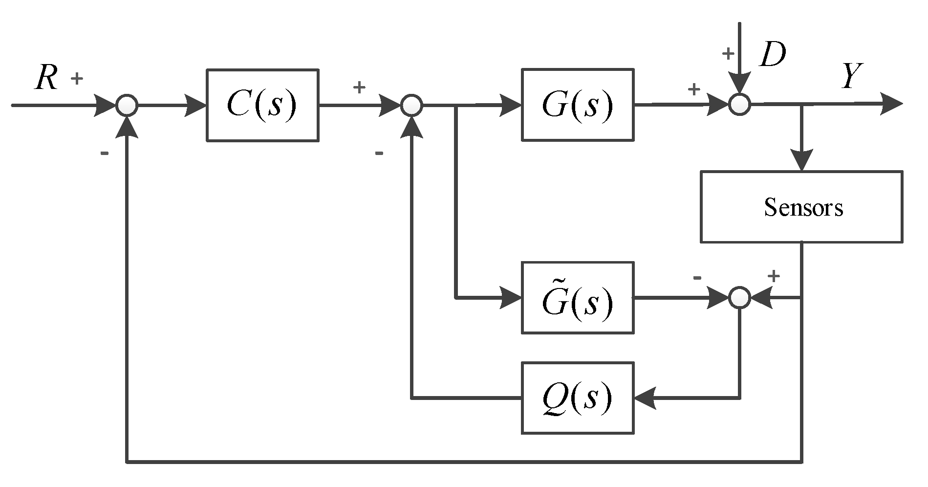
After being fused, the VGYR and the FOG can be used to measure the velocities of the FSP and the external disturbances at the same time. The FOG in the MFC system is usually so heavy that it needs an additional symmetrical positioning counterweight to balance the mechanism. However, the FSP in the telescope needs to be as light as possible. Thus, the load brought by the FOG is non-negligible for the FSP. Therefore, the VGYR without weight is utilized to replace the FOG on the FSP, and the load of FSP can be reduced. With the VGYR, the VMFC system can be constructed as shown in
Figure 5. In the dotted line frame, the VGYR is obtained by the multi-sensor frequency-domain fusion method.
According to
Figure 5, the tracking transfer function
of the VMFC can be shown as Equation (13) and the disturbance transfer function
can be expressed as Equation (14).
Since the VGYR is obtained from the multi-sensor frequency-domain fusion method, the bandwidth of the VGYR is as high as that of the MEMS accelerometer. The bandwidth of the AFC loop is three times as that of the VFC loop, but the bandwidth of the former is also much lower than that of the MEMS accelerometer. Therefore, is true in the entire bandwidth of the VFC loop. So, the tracking transfer function shown in Equation (13) can be approximatively expressed as Equation (15). Similarly, the disturbance transfer function shown in Equation (14) can be transformed into Equation (16).
According to Equations (1) and (15),
is clear, so utilizing the VGYR to build the VMFC has no effect on the tracking ability of the system. By comparing Equations (2) and (16),
can be derived. That is to say, by using the VGYR, we can still achieve the superposition of the three loops’ disturbance suppression capabilities. So, the almost same tracking capability and disturbance suppression effects of the MFC system can be achieved, by using the CCD and MEMS accelerometers only. At the same time, the VMFC system can also reduce the load and space requirements of the FSP, so it is beneficial for the higher driving capacity of the motor.
4. The Virtual Multi-Loop Feedback Control System with Measured Disturbance Feedforward Method
We have known that the MFC system and the DOB method have insufficient disturbance suppression ability due to their defects. The VGYR can replace the FOG to build the VMFC system, and it has almost the same performances with the MFC system. Although the drift still limited the disturbance suppression ability in the low frequency range of the VMFC system, the VGYR and the replaced FOG can measure the extra velocity information to get the better control performances of the system. Because the weight of the FOG is not negligible for the FSP, the VGYR without weight replaces the FOG to build the VMFC system. The replaced FOG has almost no effects on the inertial of the telescope’ frame when compared with the huge weight of the frame. Therefore, the replaced FOG is installed on the frame of the telescope to measure the velocity of external disturbances. Based on the VGYR and the replaced FOG, the VMFC system with the MDF method is proposed to suppress more vibrations as shown in
Figure 6. In this figure,
is the velocity of the disturbances,
is the external disturbances transfer characteristic, and
is the feedforward compensator.
On the basis of the VGYR’s characteristic
in the entire bandwidth of the VFC loop, the tracking transfer function
of the system can be expressed as Equation (17). Compared with Equation (15) of the VMFC system, there is no compensator
in the tracking transfer function
. Thus, it is clear that the VMFC with MDF method does not change the tracking characteristics of the system, so it will not affect the stability of the system. In other word, when the compensator
is designed to feed forward the measured disturbances, it is not constrained by the stability requirements of the system, which is totally different from the DOB method. This is also the key reason why the proposed method can suppress more disturbances in the wider frequency range.
The disturbance transfer function
of the VMFC with MDF method can be expressed as Equation (18). Compared with the disturbance transfer function of the VMFC system Equation (16), the disturbance suppression ability of the system can be further improved by the feedforward compensator
. Besides, the compensator
has no stability constraint. As a result, the design of the compensator
is only related to the disturbance suppression requirements.
Since the bandwidth of the AFC loop is as three times as that of the VFC loop,
is true in the entire bandwidth range of the VFC loop. The enhanced disturbance suppression ability
brought by the feedforward compensator
can be expressed as Equation (19).
Figure 6 shows that, before feeding forward disturbances, the disturbances are once suppressed by the AFC loop, so
is the external disturbances transfer characteristic from the frame to the FSP with the AFC loop. This means that
is the superposition of the passive suppression ability of the telescope’s mechanical structure and the active suppression ability of the AFC loop. When the inner AFC loop is achieved, its active suppression ability
is expressed as Equation (20). The external disturbances transfer characteristic of the system can be depicted as Equation (21) after the passive suppression ability of the mechanical structure is expressed as
.
In order to suppress as many disturbances as possible, we assume that
is true. According to Equations (19) and (21), the design of the ideal feedforward compensator
is presented as Equation (22), which is a causal system actually.
Compared with the DOB methods of Tang. T, Deng. C and Deng. J [
25,
26,
27,
28], the VMFC with MDF method is not limited by the system’s causality and stability restrictions. Although drift still limited the disturbance suppression ability in the low frequency range of the VMFC system, the VMFC with the MDF method can reject much more vibrations in the wider frequency range, which is benefit from its causal ideal feedforward compensator. Therefore, this method gives full play to the function of the disturbance feed-forward method. The disturbance suppression ability and the stable precision of the system can be effectively improved.
5. Experiments
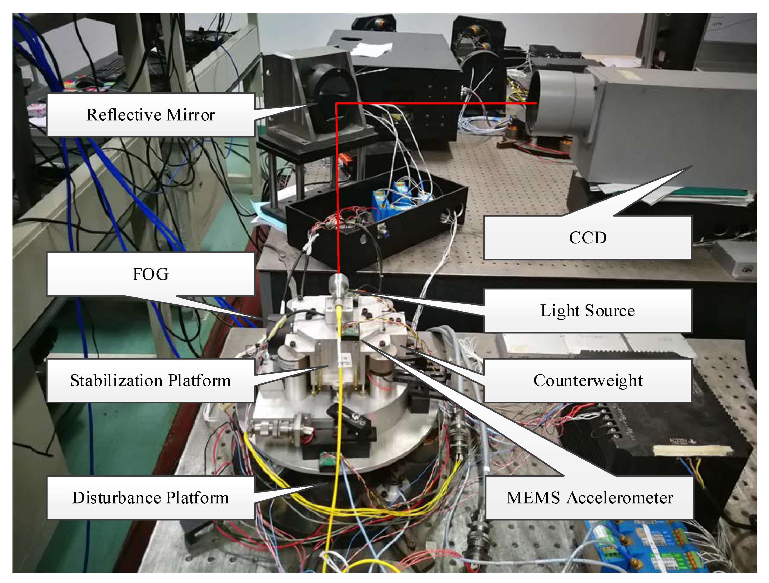
The experimental devices in
Figure 7, which are designed to stabilize the laser light, are used to verify effectiveness of the proposed method. There is a stabilization platform installed on the disturbance platform, and both platforms are driven by voice coil motors. The disturbance platform is used to simulate the external disturbances to disturb the stabilization platform, and the stabilization platform is utilized to suppress the disturbances and to stabilize the laser light. A digital dynamic signal analyzer produces the sinusoidal signal, which is used to set the simulated disturbances. We use the single-axis motion to verify the control algorithm because the platform has two symmetrical axes. The laser light is reflected by a mirror and detected by the CCD (TMC-6740CL, JAI, Denmark.). The CCD outputs the position errors between its center position and the laser light, and the position errors is used to control the stabilization platform. The FOG (XW-GS1898S, Starneto, Beijing, China) and MEMS accelerometers (Model 1221, SILICON DESIGNS, Seattle, WA, USA) are installed on the platform to measure the velocity and acceleration of the platform as shown in the figure. The output of the system can be processed by the dynamic signal analyzer. The CCD has a 680*480 image array and each pixel is 16 subdivided in the signal processing unit for a better resolution. Combined with the imaging optical system the achieved angular resolution is 0.2”. The signal updating frequency of the system is 100 Hz with 0.02 s time lag. The FOG and the MEMS accelerometers both work at the frequency of 5 kHz, whose weights are 570 g and 0.62 g, respectively. To measure the disturbance suppression ability of the system, the stabilization platform works on the closed-loop mode and the disturbance platform operates on the open-loop mode.
5.1. The Virtual Gyroscope
In order to build an extra virtual sensor to get more information of the system, we use the CCD and the MEMS accelerometer to form the VGYR with multi-sensor frequency-domain fusion method. The MEMS accelerometer we used has severe drift when its work frequency is less than 1 Hz. In order to avoid the drift’s negative impact on the VGYR, we use the position differential of the CCD with outstanding characteristics in the low frequency range to correct the acceleration integral of the MEMS accelerometer. The cut-off frequency of the low-pass filter
and high-pass filter
is designed as 1 Hz, so we can design the fusion filter
as Equation (23). Since the CCD has a time lag of 0.02s, the characteristics of VGYR can be expressed as Equation (24).
To verify the effect of the VGYR, the FOG is also installed on the stabilization platform to directly measure the velocity. The experiments are carried out on the stabilization platform. We provide the sinusoidal input of 0.5 Hz, 1 Hz, 10 Hz, and 40 Hz to the stabilization platform, respectively. The FOG and the VGYR are used to measure the sinusoidal motion of the stabilization platform, and the outputs of the FOG and VGYR are compared. The time-domain data of the experimental results are shown in
Figure 8. It is clear that the output of the VGYR lags behind that of the FOG. According to the characteristic of the designed VGYR (10), it is true that there is a little lag in the output of the VGYR when it is compared with the real velocity. In the low frequency range such as 0.5 Hz, the position differential of the CCD is used to estimate the velocity, which lags behind the real velocity by one frame. In the mid-high frequency range such as 10 Hz and 40 Hz, the acceleration integral of the MEMS accelerometer is regard as the measured velocity. However, the filters of the VGYR bring about a little lag. That is the reason why there is also a little lag in the output of the VGYR in the mid-high frequency range. That said, the lag is much smaller when compared with the relevant cycle time in the mid-high frequency range. Therefore, the output of the VGYR can keep up with the velocity of the moving stabilization platform.
To explain the measuring performance of the VGYR more accurately, we compare the characteristics of the FOG and the VGYR in frequency domain as shown in
Figure 9. From the figure, we can find that the VGYR has the same measuring characteristics with the FOG below 70 Hz. In the high frequency range, the characteristics of the FOG and the VGYR are influenced by resonances. Compared with the FOG, the VGYR has better performance between 100–200 Hz. This is because the characteristics of the VGYR depends on the MEMS accelerometer. The MEMS accelerometer has some advantages such as small size, light weight and high bandwidth. So, its resonance frequency is higher, and the VGYR also has a higher resonance frequency. Although there is tiny lag brought by the filter of the VGYR in the mid-high frequency range, it is much smaller than the cycle time in this frequency range as shown in
Figure 9. According to the experimental results, in the bandwidth of the VFC loop, the VGYR is fully capable of measuring the velocity of stabilization platform; furthermore, it is even better than the FOG.
5.2. The Virtual Multi-loop Feedback Control System
After effectiveness is verified, the VGYR can replace the FOG to build the VMFC system, which can effectively reduce the load of FSP. In order to build the VMFC system, the AFC loop is required to be firstly constructed. In the case of the acceleration open loop, we use the MEMS accelerometer and the dynamic signal analyzer to scan the stabilization platform from 1–1000 Hz. The measured frequency response results are numerically fitted, and the nominal plant
of the controlled object can be obtained, as shown in Equation (25).
After obtaining the nominal plant
of the controlled object of the AFC loop, we can design the acceleration closed-loop controller
as shown in Equation (26), in which the inertial link with low cut-off frequency is used to partially weaken the differential link of
. The controller
with the inertial link can avoid integral saturation when there is massive drift brought by the MEMS accelerometers. As a result, the controller
cannot suppress enough disturbances in the low frequency range. After the AFC loop, the characteristics of the controlled object
can be modified by the controller
. The virtual velocity closed-loop controller
can be designed as a simple PI controller, and the bandwidth of the AFC loop is designed as three times as that of the VFC loop. In the same way, we design the position closed-loop controller
as shown in Equation (27).
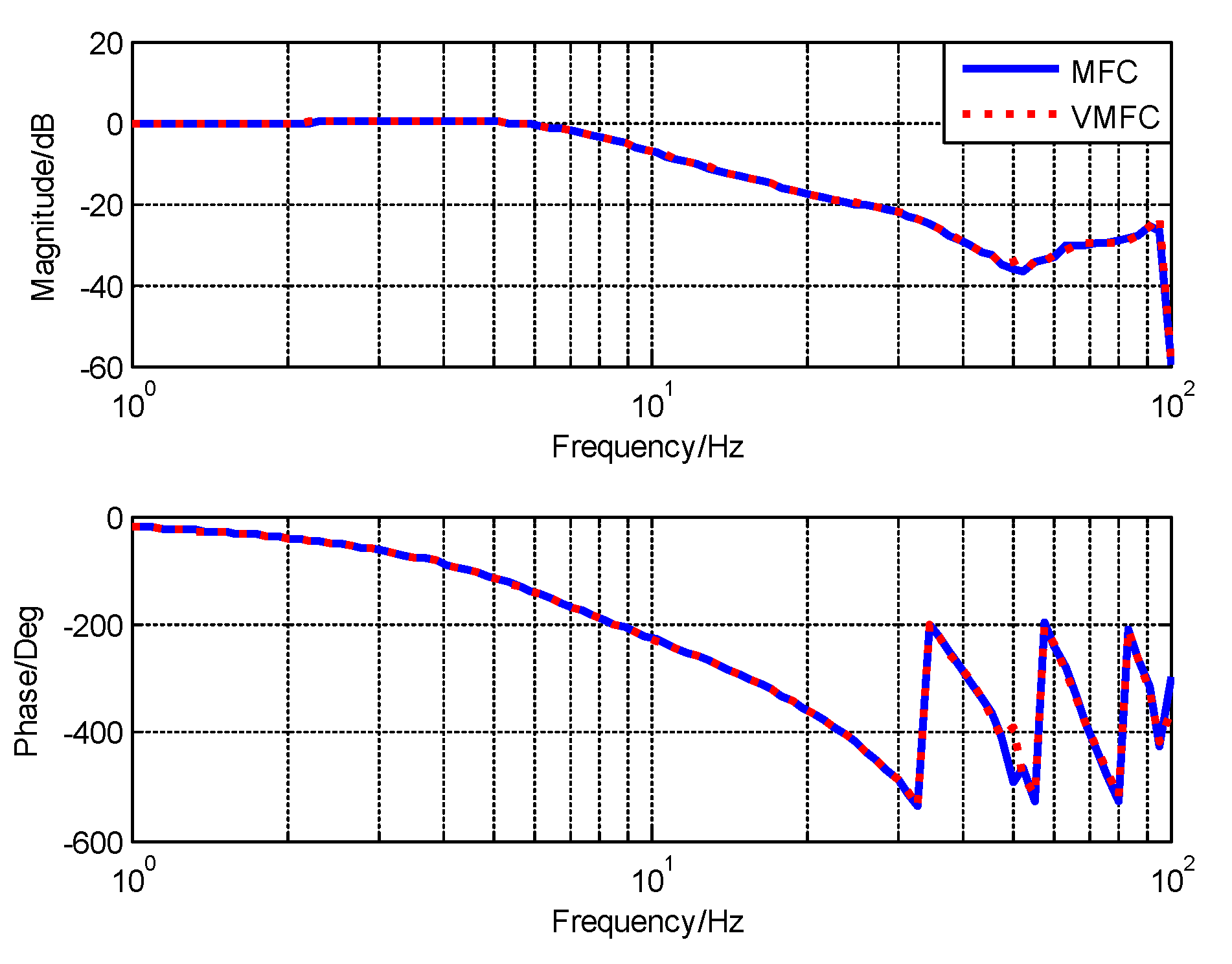
After designing the controllers, we can use the VGYR to carry out the VMFC system. To verify the function of the VGYR, we use the same controllers with the FOG and the VGYR to carry out the traditional MFC and VMFC systems, respectively. The experimental results are shown in
Figure 10 and
Figure 11. In the
Figure 10, the tracking characteristics of the MFC and the VMFC are compared. It can be found that both systems have almost the same tracking bandwidths. The
Figure 11 shows the disturbance suppression abilities of the MFC and the VMFC systems. It is clear that the disturbance suppression abilities are almost the same. Although the VGYR has better characteristics than the FOG as shown in
Figure 9, the tracking bandwidths and disturbance suppression abilities shown in
Figure 10 and
Figure 11 are hardly different. The reason is that the bandwidth of the VFC loop is lower than that of the FOG. In the bandwidth of the VFC loop, the characteristics of the VGYR and FOG are almost identical. The lag caused by the VGYR is much smaller when compared with the relevant cycle time in the mid-high frequency range. The tiny lag caused by the VGYR could lead to the slightly decrease of the stability margin of the VFC loop. However, the lag is so puny that the decrease of the stability margin is acceptable for the system. Thus, the VGYR has almost no influence on the tracking capability and disturbance suppression ability. According to the
Figure 10 and
Figure 11, the VGYR can completely replace the FOG. The experimental results can fully demonstrate the effectiveness of the VGYR. The VMFC system with the VGYR has almost the same control performances as the MFC system with the FOG.
5.3. The Virtual Multi-loop Feedback Control System with Measured Disturbance Feedforward Method
Through the experiments in the previous section, we have verified the effectiveness of the VMFC system with the VGYR, and it can completely replace the MFC system with the FOG. Although the drift still limited the disturbance suppression ability in the low frequency range of the VMFC system, the VGYR and the replaced FOG can build the VMFC system with MDF to reject more disturbances, which is not limited by the stability restriction and the drift. Compared with the huge frame the telescope, the FOG has almost no effects on its inertial. Moreover, in our experimental system, the replaced FOG is installed on disturbance platform to measure the velocity of external disturbances.
To verify the disturbance suppression ability of the proposed method, the compensator
is requisite. So, we firstly measure the external disturbance transfer characteristics in the open-loop case. As shown in
Figure 12, the open-loop external disturbance transfer function
from the disturbance platform to the stabilization platform is obtained by the identifying method, which is the passive disturbance suppression ability of the mechanical structure as shown in Equation (28).
When we build the VMFC with MDF system, the active disturbance suppression ability of the system should be considered before feeding forward disturbances. According to the controlled object
and the controller
of the AFC loop, the active disturbance suppression ability
can be obtained as shown in Equation (29).
According to the design method of the feedforward compensator in Equation (22), the ideal feedforward compensator
is designed as Equation (30), which is a physically feasible causal system.
The DOB control method in the AFC loop based on the MFC system has been proposed by Deng. C, in which the same sensor including the CCD, FOG and MEMS accelerometer are used [
27]. Due to the constraints of stability and the non-causal ideal filter, the filter
of the DOB is designed as Equation (31).
We use the MFC with DOB and the VMFC with MDF to reject disturbances, and we compare the effectiveness of disturbance suppression. The time-domain position errors of the stabilization platform are compared when the stabilization platform is disturbed at 2 Hz, 6 Hz, 10 Hz and 30 Hz, respectively. The experimental results are shown in
Figure 13, and the root mean squares (RMS) of the errors with different methods are listed in
Table 1. As shown in the
Figure 13 and
Table 1, the MFC with DOB have almost no extra disturbance suppression effect in the low frequency range, whereas the VMFC with MDF method can effectively suppress more disturbances. In the middle frequency range, the RMS of the VMFC with MDF is still lower than that of the MFC with DOB. Thus, the proposed VMFC with MDF can get a better stable precision.
To illustrate the differences of the two methods more clearly, we compare their disturbance suppression abilities in the frequency domain, which is shown in
Figure 14. Under the background of using of the long-distance laser communication system on the movable platforms, the external vibrations that cause the decline of the stable precision of the optical path are mainly distributed below 40 Hz, namely the low and middle frequency ranges within the range of 1–100 Hz [
7,
8]. Especially in the low frequency range under 10 Hz, the disturbance in the frequency range has the most obvious influence on the stable precision of the system, so this is also the main challenge we are facing. In
Figure 14, the MFC method with DOB can only improve the disturbance suppression ability in the middle frequency range within the range of 10–30 Hz. In fact, it makes no difference for the low-frequency disturbances which most affect the stable precision. The reason is that it sacrifices the disturbance suppression ability to guarantee the stability of the system. Thus, the compromise made by the filter
leads to the insufficient disturbance suppression ability in low frequency range. Different from it, the proposed VMFC with MDF method is not limited by the causality and stability restrictions of the system. The external disturbances can be fed forward and counteracted by the causal ideal compensator
. The benefit from this advantage is that the VMFC with MDF method can reject much more disturbances than the MFC with DOB method in the wider frequency range within 1–40 Hz, which present the superiority of our approach.
In the high frequency range, it is less obvious to see the disturbance suppression ability improve with proposed approach, because the bandwidth of the VFC loop limits the driving capacity of the motor. The high-frequency disturbances’ suppression of the system mainly relies on the passive disturbance suppression ability of the mechanical structure of the system. However, in the lower frequency range below 1 Hz, limited by the low signal-to-noise ratio of the CCD in our experimental system, the disturbance suppression performance cannot be distinguished by the experimental results, but this does not affect the effectiveness of our method to achieve the higher stable precision. But when compared with the current methods, the proposed method can exactly improve the disturbance suppression ability of the system in the low and middle frequency ranges of 1–100 Hz as shown in
Figure 14. From the experimental results, the function of the disturbance feedforward control method is fully exerted by using the proposed method. As a result, under the background of using of the long-distance laser communication system on the movable platforms, the method proposed in this study can effectively improves the stable precision and the disturbance suppression performance range in the wider frequency range, which includes the additional low frequency range.


