1. Introduction
The appearance of low-cost GPS chipsets on the market coincided with a real revolution. Initially, the devices, whose costs were high, were designed only for military use or high-end geodetic application. In 1999, the phone manufacturer Benefon launched the first commercially-available GPS phone Benefon Esc! Since then, many steps forward have been made. The Ericsson mobility report of June 2018 states that 4.8 billion smartphones with GNSS chipsets are active worldwide.
A new revolution started in May 2016 when Google, during the annual developer-focused conference, announced that raw GNSS measurements will be available to apps in the Android Nougat operating system. For roughly 17 years, the pseudorange, doppler, and carrier phase observables were not available to developers, as these data were protected by chip manufacturers; only the position computed by the GNSS chipsets was available to everyone. Before the Google announcement, measurements collected by a smartphone could not be processed by post-processing software, and therefore, under the best conditions, positioning accuracy could reach three meters, while under adverse multipath conditions, it degraded to tens of meters. This accuracy is very far from that obtainable using a geodetic receiver which can reach up to the centimeters level. Despite the impossibility of accessing the measurements, scientists have tried to solve the issue. A first study was conducted by Pesyna et al. [
1] in 2014. They used a smartphone antenna to receive GNSS signals and feed a software-defined receiver that generated carrier phase and pseudorange observables. Measurements collected were then processed with differential techniques. They have shown that the difference in performance is due to the smartphone antenna which does not have a good multipath suppression with respect to geodetic antennas. In 2015, Kirkko-Jaakkola et al. [
2] were able to access the raw GNSS measurements of a Nokia Lumia 1520 smartphone equipped with a Qualcomm GNSS receiver thanks to a suitable firmware specifically modified by Microsoft mobile. They showed that smartphone measurements were noisy and suffered from a significant number of outliers in comparison with those collected by a U-Blox low-cost receiver and achieved only a meter-level positioning. In 2016, Humphreys et al. [
3] were able to access GNSS raw measurements collected by a modified Samsung Galaxy S5 smartphone equipped with a Broadcom GNSS chipset running a customized Android Marshmallow (provided by Broadcom) including a modified GPS library that recorded RINEX (Receiver Independent Exchange Format) files to the phone’s storage card. Their analysis revealed that under typical smartphone use, the effects of local multipath was the main drawback to achieving a centimeter-accurate smartphone positioning.
After Google’s announcement in November 2016, Banville and Van Diggelen [
4] analyzed GNSS data collected by a Samsung Galaxy S7 smartphone running the Broadcom 4774 GNSS chipset at the Googleplex, located in Mountain View, California. They used an engineering build of the Android N OS. They examined the quality of the data with the purpose of deriving precise positioning information from a smartphone, the main issues they encountered were due to the quality of the antenna and the duty cycling of the GNSS receiver. In 2016, Yoon et al. [
5] were able to apply differential global navigation satellite system (DGNSS)-correction to a commercial smartphone without accessing raw data. The results they achieved showed an accuracy improvement by about 30–60%. In 2017, Alsubaie et al. [
6] proposed a methodology to increase the accuracy of direct geo-referencing of smartphones using relative orientation and smartphone motion sensor measurements as well as integrating geometric scene constraints into free network bundle adjustment.
Zhang et al. [
7] in 2017 tested a Nexus 9 tablet running the Broadcom 4752 GNSS chipset, jointly developed by Google and HTC. The tablet was equipped with Android N (version 7.1.1) and provided pseudorange data, navigation messages, accumulated delta ranges, and hardware clocks for GPS and GLONASS. They analyzed and assessed GPS L1 observations and studied the positioning accuracy of both static and kinematic observations concluding that it is difficult to obtain meter level positioning accuracy using only pseudorange observations from smartphones. Siddakatte et al. [
8] investigated the performance of smartphone measurement and location data under various scenarios using internal and different external antenna configurations with the Huawei Mate9 phone equipped with a BCM4774 GNSS chipset.
Until May 2018, the GPS chipsets mounted on smartphones were single-frequency. In some cases, they were already multi-constellation, but the mono frequency extremely limited the performance because the ionospheric error could not be eliminated but only estimated using a single frequency model like Klobuchar one. On 31 May 2018 the world’s first dual-frequency GNSS smartphone produced by Xiaomi was launched. It is equipped with a Broadcom BCM47755 chipset. It is a dual-frequency (E1/L1+E5/L5) GNSS chip [
9]. This smartphone with its chipset, utilizing Android dual-frequency raw GNSS measurements represents one of the most recent advances and developments of GNSS devices, allowing to achieve decimeter level positioning with a smartphone. Global Navigation Satellite System devices can be used in a range of mobility services that smart cities have to provide like parking, last-mile delivery, vehicle sharing, emergency response, and autonomous driving. As a consequence, to fulfil the requirements for location-based services and vehicle navigation, the number of these devices is rapidly increasing. In order to limit the number of GNSS receivers, one might think of using the receivers embedded in smartphones. However, these types of consumer receivers installed so far on smartphones do not always have characteristics that meet the ever-increasing levels of precision required for this type of application in smart city contests. The Android Xiaomi Mi 8 smartphone with its chipset, utilizing dual frequency multi-constellation code and carrier phase raw measurements is one of the most recent developments of GNSS devices. The availability of raw measurements can result in the advantage of using the smartphone as rover for real time kinematic (RTK) positioning to achieve higher precision. Tracking of multiple GNSS satellite signals maximizes the availability of a position fix even in harsh environments such as urban canyons. It is interesting to evaluate the performance improvements due to this type of smartphone, as it represents an important progress towards evolution of smartphones in high-precision GNSS receivers. This advance could contribute significantly to reduce the number of the used devices enabling green communication solutions for sustainable smart cities.
In July 2018, NSL’s FLAMINGO (Nottingham Scientific LimitedFulfilling enhanced Location Accuracy in the Mass-market through Initial GalileO services) Team evaluated the capabilities of the Xiaomi Mi 8 by comparing the accuracy of the internal PVT (Position Velocity Time) solution to that of a Samsung S8, embedded with the older single frequency Broadcom 4774 chipset, to that of Septentrio PolaRx5e, a geodetic class GNSS receiver in a static scenario. This test did not use smartphone raw data [
10]. The same team explored the quality of the raw measurements from Xiaomi Mi 8 [
11] and they found that the carrier phase was not affected by duty cycles. Warnat et al. [
12] focused their attention on the analysis of the accuracy of pseudorange, double difference for both carrier phase, and code observables and estimate code multipath in an open sky environment.
The main aim of this work is to achieve the position by using multi-constellation, dual frequency pseudorange and carrier phase raw data collected from a Xiaomi Mi 8 smartphone. The availability of dual frequency raw data allows us to assess the multipath performance of the chipset. The smartphone’s performance is compared with those of a geodetic receiver. The experiments were conducted in two different scenarios to test the smartphone under different multipath conditions. Given the good quality of the Galileo measurements collected by the Xiaomi Mi 8, as demonstrated by Warnat et al. [
12], we also tested the performance of Galileo E5a raw pseudorange by calculating a single-point code positioning and comparing with those of the E1 signal. Unlike Reference [
12], we make an analysis in terms of the absolute position obtained in both single-point and differential mode, while regarding code multipath we estimate it also in a difficult scenario. Urban situations, where most of the smartphones are used, are particularly affected by multipath that is considered the dominant source of GNSS ranging errors. In this scenario, several blunders in the measurements are present [
13].
Increasing the number of satellites used in positioning solutions is key to achieving better accuracy with mass market receivers. Thus, the availability of multi-constellation data must be exploited. This is one of the first studies that tests the multi-constellation performance of smartphone GNSS raw data in conjunction with code multipath assessment, as all the above mentioned studies analyzed only GPS observations on L1 frequency. An exhaustive exposition of the multi GNSS positioning could be found in References [
14,
15].
The experimental setup adopted is detailed in
Section 2 where the hardware and software used are shown, and the sites where the measurements were collected are described. The methodological aspects followed to conduct our analysis are described in
Section 3. The experimental results are reported in
Section 4 and discussed in
Section 5, and some final conclusions are drawn in
Section 6.
2. Experimental Setup
The smartphone used was a Xiaomi Mi 8, embedded with a Broadcom BCM47755 chip. This chip is the first dual frequency chip expressly developed for a smartphone. It provides access to the single frequency (L1/E1) GPS, Galileo and GLONASS, as well as a second frequency L5 and E5a for GPS and Galileo, respectively. The Xiaomi Mi 8 can provide pseudorange data, navigation messages, accumulated delta ranges, and HW clocks for GPS, GLONASS, and Galileo. Here we want to recall that not all smartphones are able to log GNSS raw data. A list of devices capable of providing raw measurements is maintained at the URL
https://developer.android.com/guide/topics/sensors/gnss. Information also includes constellations availability and the availability of the phase measurements. All devices need to run Android Nougat or later. The main issue to solve in order to obtain good performances from the GNSS receiver of the smartphone is the battery consumption. The smartphone vendors implement several techniques to maintain a low power consumption. The most common strategy used is the duty cycle: the receiver tracks GNSS data for 200 ms before shutting down for 800 ms [
4]. Without tracking continuity, several cycle slips may occur between two consecutive measurements, severely limiting the use of such advance phase techniques as real time kinematic (RTK) or precise point positioning (PPP). As the NSL’s FLAMINGO Team showed in Reference [
11], the carrier phase observations collected from Xiaomi Mi 8 are not affected by duty cycles.
In order to evaluate the smartphone’s performance, we used as a term of comparison the TOPCON GRS-1 geodetic receiver fed by the TOPCON PG-A1 antenna. It is a geodetic dual frequency (L1/L2) dual constellation (GPS/GLONASS) geodetic antenna. The biggest difference between the geodetic receiver and the smartphone is the antenna with which they are fed. As claimed by Zhang et al. [
7] based on the study of Pathak et al. [
16], the smartphone GNSS antenna uses linear polarization, making it susceptible to multipath effects from GNSS signals reflected by surfaces near the antenna. Thus, the smartphone antenna is highly sensitive to low-quality GNSS signal capture compared with the geodetic-quality device expressly designed to minimize the multipath effect. This is one of the main drawbacks to overcome in order to achieve a GNSS smartphone positioning accuracy comparable with that of geodetic receiver.
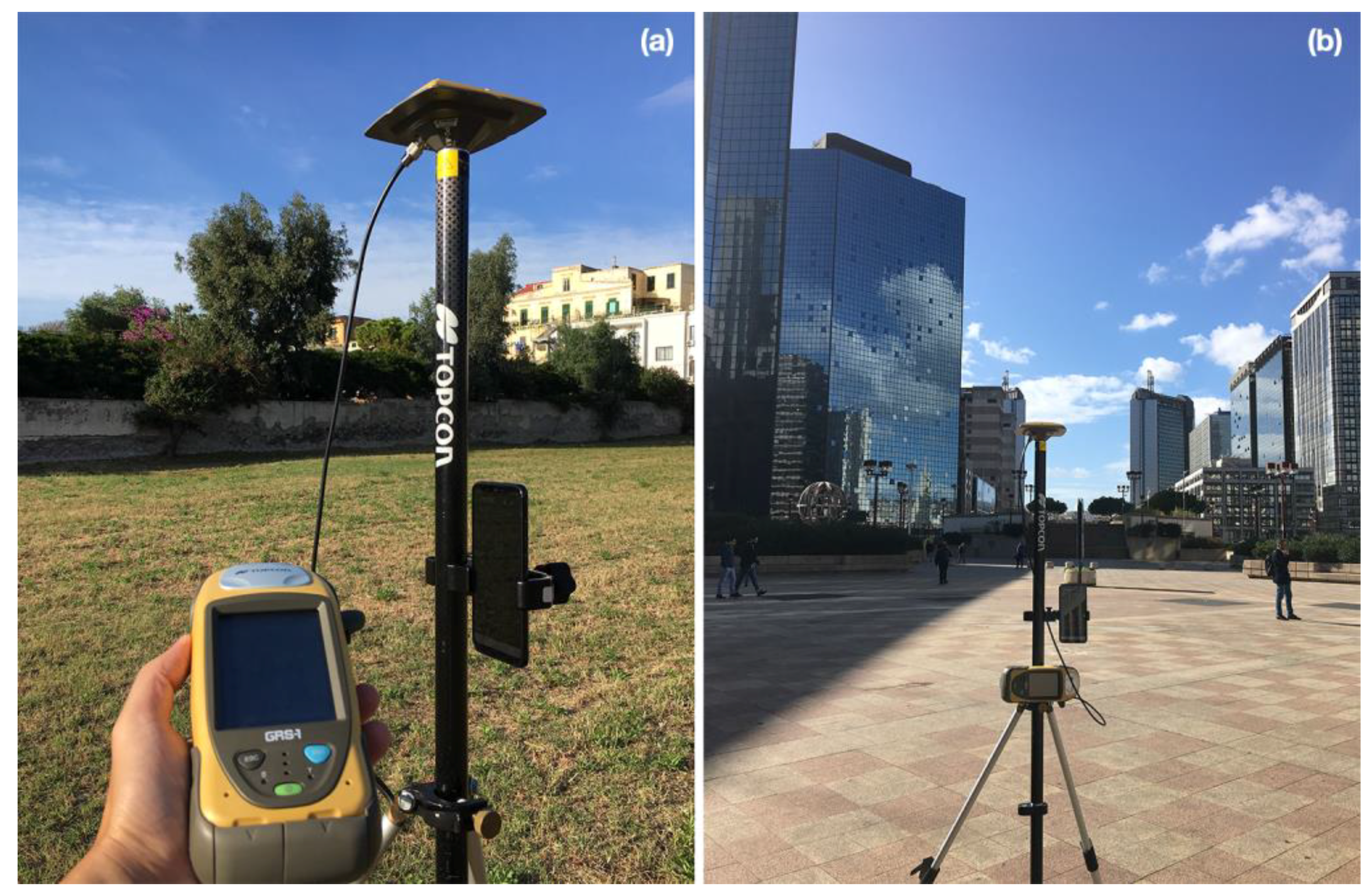
In order to investigate the performance of the smartphone we applied our analysis to the measurements captured in two different scenarios. The first dataset was in a site where it is expected to be a low-multipath environment. The geodetic receiver and smartphone were placed in Portici site (Naples, Italy). The experiment was carried out using one-hour RINEX 3.0.3 file at 1 Hz acquired by the smartphone during the 3 October 2018 and 1 Hz RINEX 2.11 files acquired by geodetic receiver. The second dataset was collected on 12 October 2018 over a time span of one hour in a strong multipath scenario in Centro Direzionale (CDN) site (Naples, Italy) by using the same instrumentation. This was a “difficult” environment in which the receivers were surrounded by buildings. It can be seen as a typical example of an urban canyon where many GNSS signals are strongly degraded by multipath effects or blocked by skyscrapers. The analysis was performed for all visible satellites for both the experiments during the whole observation periods.
As can be clearly seen from
Figure 1a, the smartphone was not placed on the ground but positioned in such a way as to simulate its use by a human who keeps it in his hands at a height of about 140 cm.
3. Methodology
The Android system provides a series of functions called API (application programming interface) through which developers can interact with all the sensors (including the GNSS chipset) contained within the smartphone. Obviously, every different version of the Android system has different types of APIs. Until the Marshmallow version of the Android system it was possible to get location information through the
android.gsm.location API [
17]. This function allows users access to (a) GPS satellite information (C/No, azimuth, elevation) if that satellite it has been used in the PVT solution; (b) basic NMEA (National Marine Electronics Association) sentences, to PVT solution obtained by combining data from different sensors (GNSS, Wi-Fi, mobile networks) with the proper time stamp. This API actually makes the GNSS receiver like a black box: the acquisition and tracking blocks decode navigation message and generates the GNSS pseudoranges and carrier phase observables; these are corrected using the information contained in the navigation message (clock errors, ionosphere and troposphere, etc.); finally, the position, velocity, and time (PVT) solution is calculated and output by the chipset. Thus, users were not allowed access to raw GNSS measurements and so pseudoranges and carrier phase observables cannot be used. Starting from the Nougat version, Android introduces the new Location API
android.location. It allows access to both the PVT solution and the GNSS raw measurements by which the GNSS observables can be calculated. Thanks to this API, some Android applications capable to log raw GNSS measurements like: GnssLogger [
18], Geo++ RINEX Logger [
19], and rinex ON [
20] were developed.
The GnssLogger app was released by Google along with its source code in 2016. The app allows to log the measurements described in the GnssClock and GnssMeasurement classes in the online
android.location API documentation [
21]. Unfortunately, this app does not provide directly pseudorange or carrier phase observables and does not log ephemerides data. Thus the Google-developed logger does not allow to directly save raw data in RINEX format. The Geo++ RINEX Logger app was released in 2017 by the Geo++ company. It provides directly GNSS observables in RINEX format but does not provide ephemerides data. The rinexON app was released at the end of June 2018 by FLAMINGO team. It provides directly both observation and navigation file in RINEX 3.0.3 format for Galileo, GPS, and GLONASS satellite system. We decided to use rinexOn app thanks to this feature as data collected by smartphone can be further processed in post processing GNSS software.
As previously mentioned, multipath is one of the main errors that corrupts the code measurements collected by the smartphone. For this reason, it has been the object of a detailed analysis. In order to characterize multipath (mp) observable has been used. The mp is a linear combination of dual frequencies code and phase measurements. It is used to characterize the magnitude of the pseudorange multipath and noise for any GNSS system by the TEQC software [
22]. Pseudorange multipath can be estimated by equations [
23]
where the subscripts 1 and 5 denote L1 and L5 bands,
and
are the estimates of the code multipath error,
and
are the code observables,
λ1 and
λ5 are the wavelengths,
and
are the carrier phase observables in units of cycles,
and
are the code multipath,
and
are the receiver noise error of the code measurements,
K is a constant term associated with phase ambiguities,
is a term associated with instrumental delays and
α = (
f1/
f5) with
f1 frequency on L1 band and
f5 frequency on L5 band. Above equations contain code multipath error, noise and unwanted terms due to phase ambiguities and instrumental delays. As can be seen from Equations (1) and (2) mp observables can be formed only if the code and phase observables are available at two different frequencies. This is one of the first studies that analyses smartphone code multipath pseudorange error. We calculated mp observables by using TEQC software. To estimate unwanted terms, we used a moving average filter [
24] taken on 900 samples [
25]. The outputs of TEQC are different files in compact3 format. In order to process these files, we developed a suitable Matlab parser (see
Appendix A).
In order to get positioning solutions, we used RTKlib software. It is an open-source software for standard and precise positioning. It supports standard and precise positioning algorithms for GPS, GLONASS, Galileo, QZSS, BeiDou, and SBAS, for both real-time and post-processing [
26]. The single-point positioning solution was achieved using the classical PVT algorithm applied on code measurements and broadcast ephemerides. Ionosphere and troposphere delays were evaluated using the Klobuchar and Hopfield model, respectively.
The carrier-based solution was achieved processing RINEX data with RTKlib in the static relative positioning mode estimating ambiguity through instantaneous strategy. In detail, a Continuously Operating Reference Station (CORS) of the Campania GNSS Network was used as base-station receiver. It is equipped with a Topcon NET-G3 dual frequency (L1/L2) dual constellation (GPS/GLONASS) receiver fed by a Topcon CR-G3 choke-ring antenna. This type of smartphone/reference station configuration forced us to perform a carrier phase based relative positioning using only the L1 frequency and the GPS constellation because the reference receiver, unlike smartphone, does not acquire L5 frequency and Galileo constellation. In addition, we also had to develop another Matlab tool with the objective of performing single point positioning using Galileo’s E5a frequency since RTKlib only uses the E1/L1 frequency and does not allow to achieve a single-point position by using the E5a frequency. This tool has been developed in such a way that the models, correction algorithms, weighting, and mask angle used are exactly the same as those used by RTKlib in its source code. Therefore, the E1/L1 positioning achieved by our software was almost the same obtained by using RTKlib, hence the results showed in the following refer to RTKlib.
The multipath analysis confirmed that the Galileo E5a showed the highest suppression of code multipath as compared to the other signals, thus we decided to compare smartphone Galileo E1 single-point positioning with E5a one.
4. Results
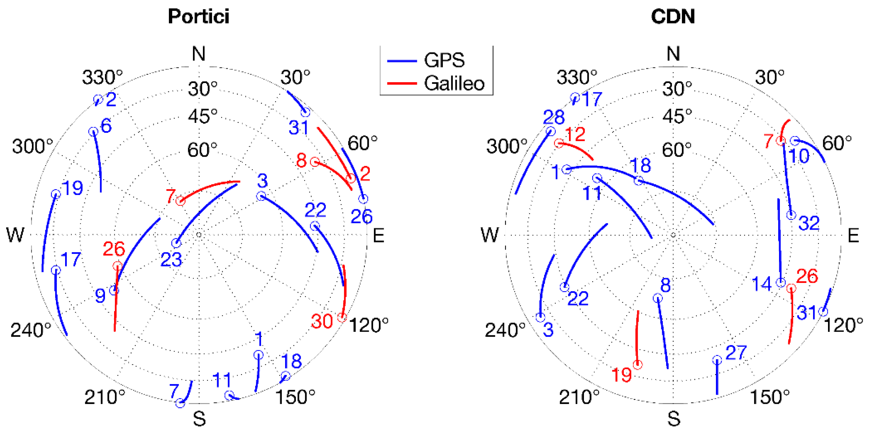
The sky plot of GPS and Galileo satellites in the Portici and CDN sites are shown in
Figure 2.
The carrier-to-noise density C/N0 output by a receiver provides an indication of the accuracy of the tracked satellite GNSS observations and the noise density as seen by the receiver’s front-end. It also indicates the level of noise present in the measurements. These values are stored in RINEX file outputted by rinexON app. The lower the signal-to-noise ratio the worse the quality of the measurements.
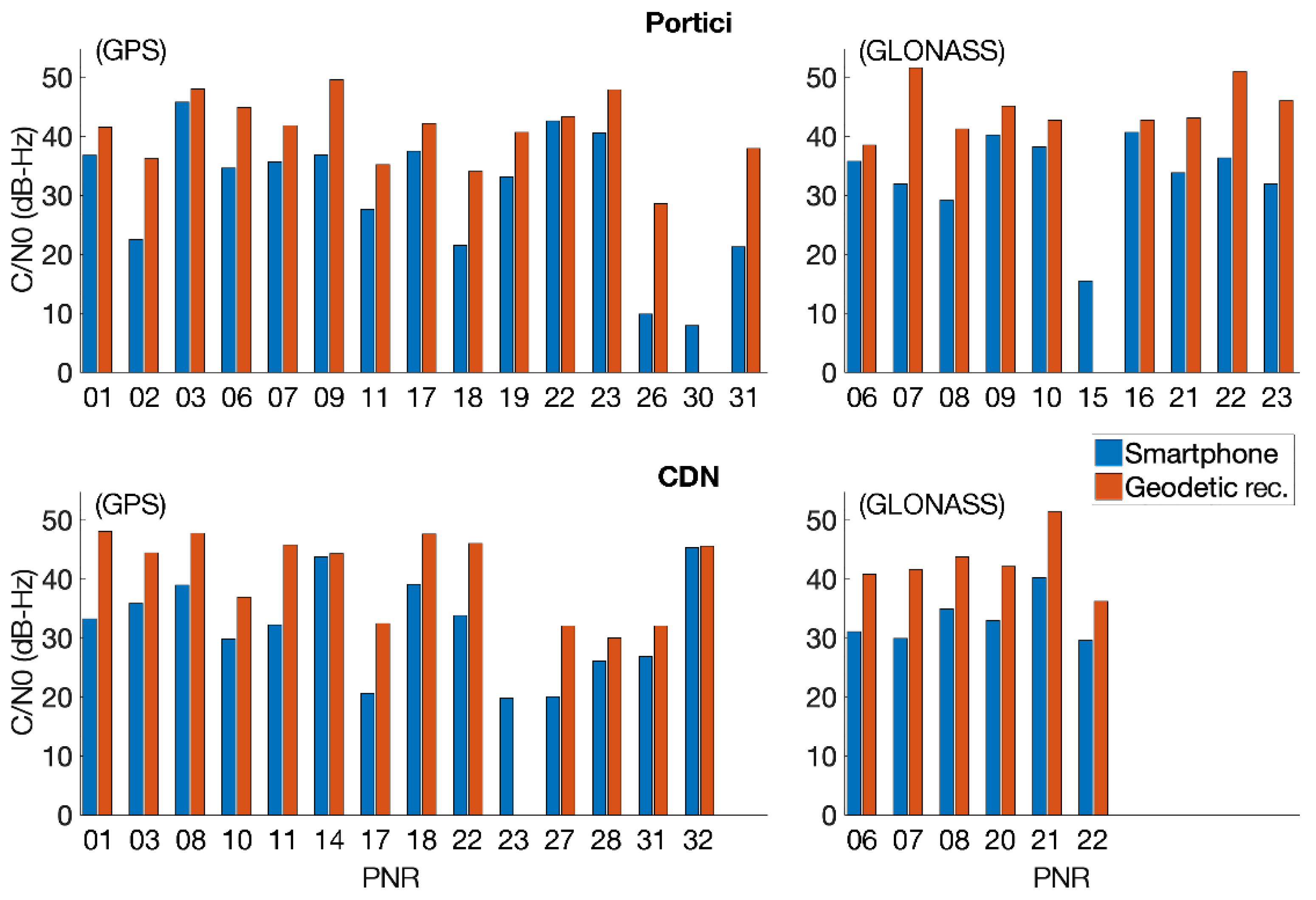
Figure 3 shows a comparison of the mean of C/N0 values for each tracked satellite between smartphone (blue bars) and geodetic receiver (red bars) in both sites. In detail, panel (a) shows the comparison for GPS satellites in the Portici data collection, panel (b) shows the comparison for GLONASS satellites in the Portici data collection, panel (c) shows the comparison for GPS satellites in the CDN data collection, and panel (d) shows the comparison for GLONASS satellites in the CDN data collection. The C/N0 is lower for the smartphone compared to the geodetic receiver in both sites and for both constellations. This is due to the limited performance of smartphone antenna with respect to geodetic one. It also captures low-quality signals that the geodetic antenna rejects. This explains the absence of the G30, R15, and G23 from panel (a), (b), and (c), respectively.
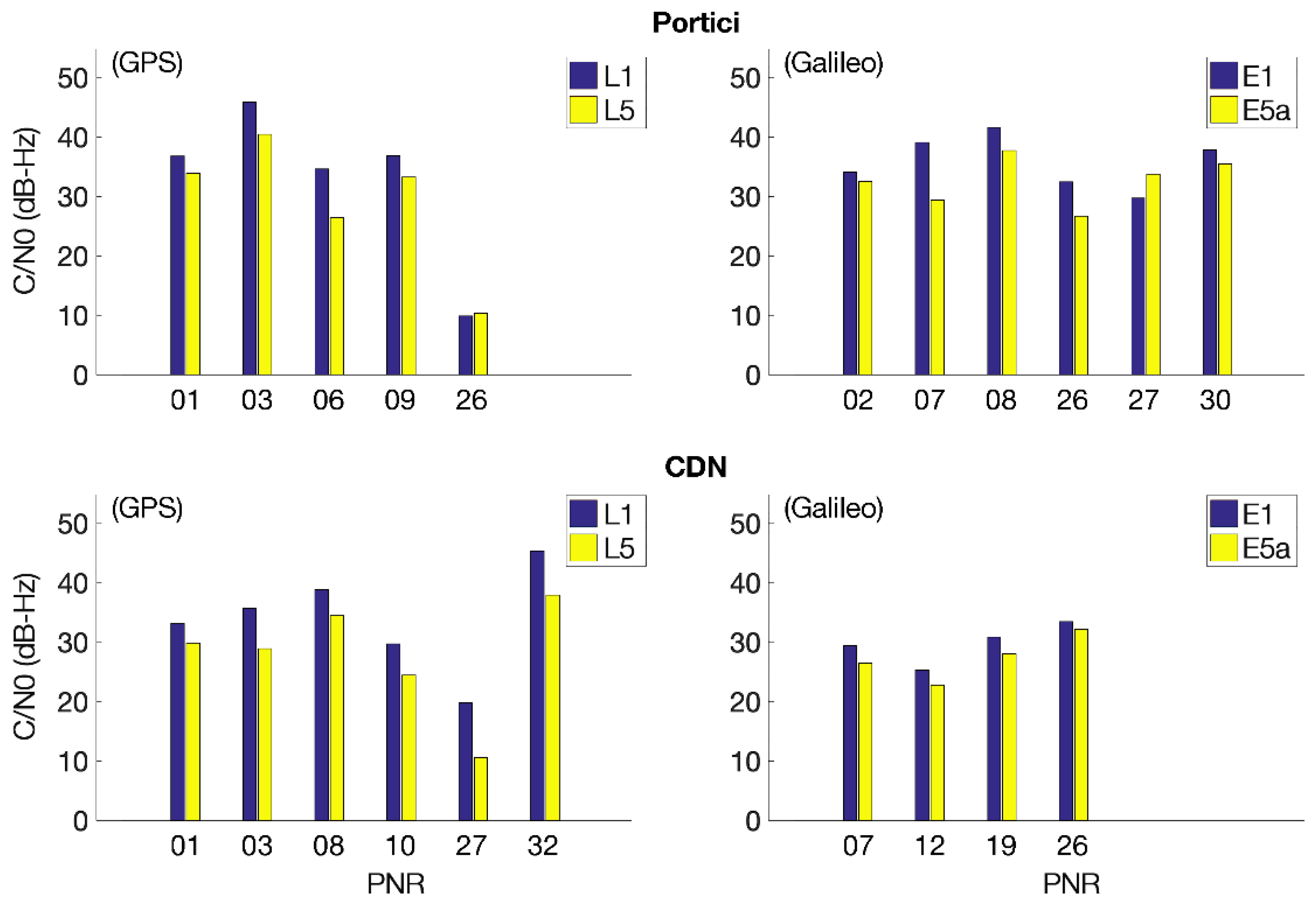
Figure 4 shows a comparison of the mean of C/N0 values between L1/E1 (blue bars) and L5/E5a (yellow bars) in both sites. In detail, panel (a) and panel (b) show the comparison for GPS and Galileo satellites, respectively, in the Portici site; panel (c) and panel (d) show the comparison for GPS and Galileo satellites in the CDN site. Figure shows that L1/E1 signals are considerably stronger than L5/E5a, for both sites.
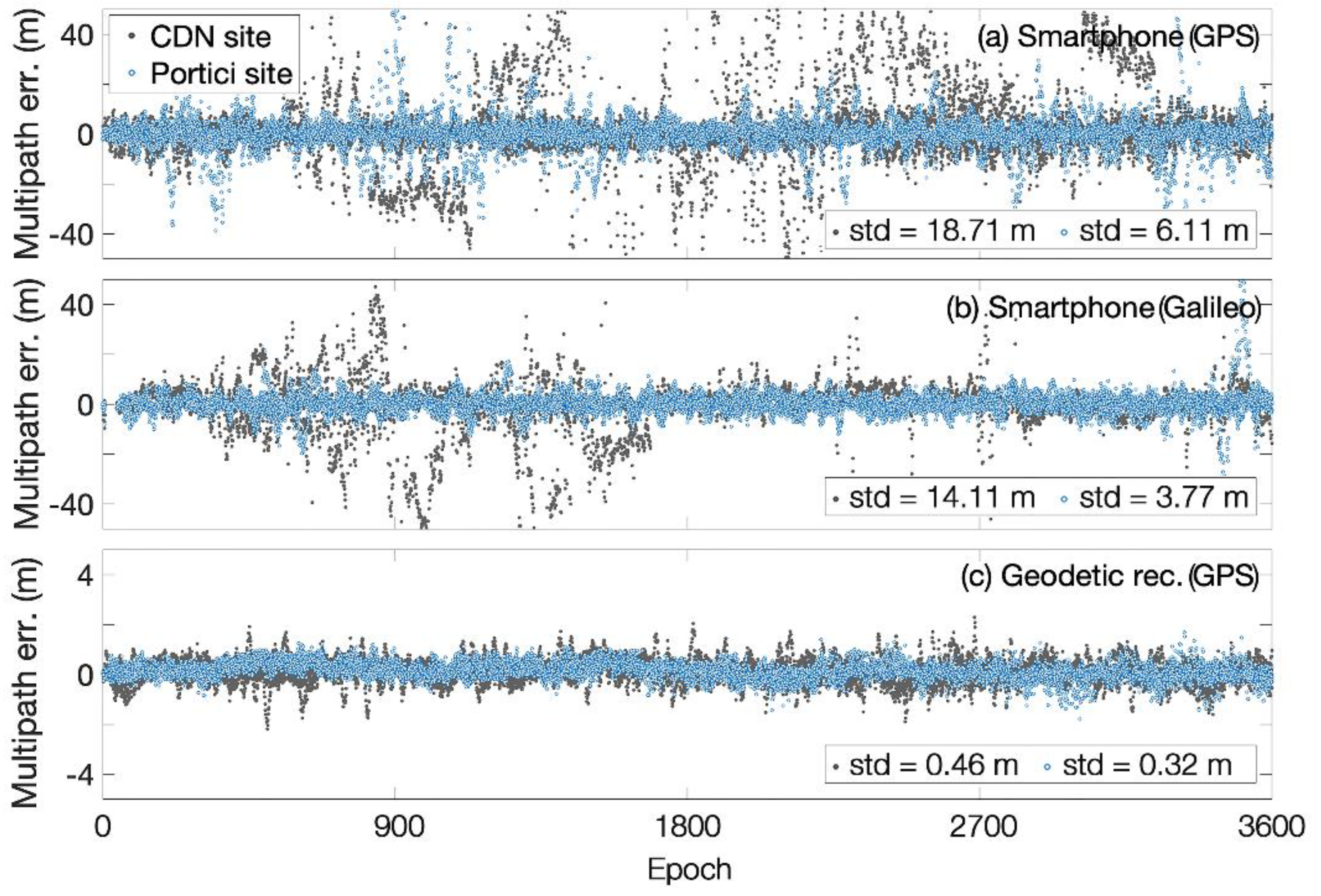
As stated before mp observables can be formed only if the code and phase observables are available at two different frequencies. Results achieved are reported below. In
Figure 5, the results showed in panel (a) are reported L1 multipath error for smartphone GPS measurements; they are obtained by using L1 and L5 frequencies. Not all GPS satellites transmit L5 frequency, therefore this analysis regards only visible satellites transmitting both L1 and L5 frequencies. Panel (b) shows E1 multipath error for Galileo smartphone measurements, they are obtained by using E1 and E5a frequencies and regard all Galileo visible satellites since each Galileo satellite transmits both frequencies. The last panel (c) shows L1 multipath error for the GPS measurements acquired by geodetic receiver. They are calculated using L1 and L2 frequencies. Looking at the figure, it is clear that the multipath on CDN site is much higher than that in Portici site both for smartphone and geodetic receiver. The multipath error standard deviation is reduced from of 18.71 m in CDN site to 6.11 m in Portici site for the GPS system and from a 14.11 m to a 3.77 m for the Galileo system. The comparison between the GPS panel (a) and the Galileo panel (b) system is interesting. It shows that considering the multipath coming from all the satellites as a whole, its standard deviation calculated on all visible Galileo satellites is lower than that calculated on all the GPS satellites for both sites. In panel (c) is reported the same analysis for geodetic receiver. Results achieved for L1 multipath error of the GPS measurements acquired by geodetic receiver show standard deviation values of 0.32 m and 0.46 m for Portici and CDN sites, respectively. They are much better than those achieved by the smartphone as expected. Results reported in all panels show that the Portici site was affected by a lower multipath compared to the CDN site as expected.
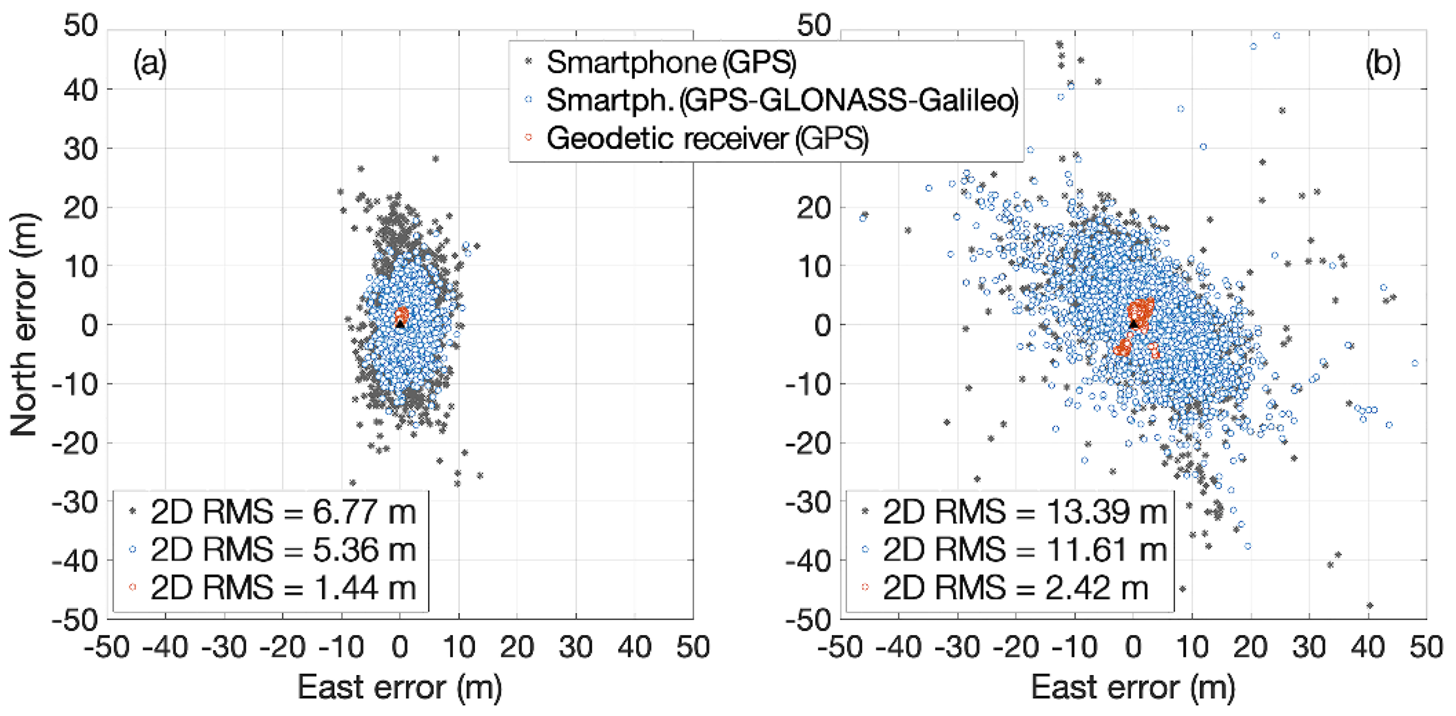
Figure 6 shows the position errors in both sites obtained using the code measurements. In both panels (a) and (b) the gray stars represent the position errors obtained using L1 GPS code measurements collected by the smartphone, the blue circles represent the position errors obtained using multi-constellation (GPS, GLONASS, Galileo) L1/E1 code measurements from the smartphone while the red circles represent the position error obtained using the L1 GPS code measurements from the geodetic receiver. As it can be seen, multipath around 900 epoch in the Portici site was very high. This is due to a lack of three seconds of data that affected the moving average filter used to estimate mp. The analysis shows, that for all configurations, the Portici site had a DRMS (horizontal root mean square error) that was halved compared to the CDN site. This was expected as the environment of the CDN presents a higher multipath as shown in
Figure 5. Equally interesting is the RMS reduction that was achieved using the multi-constellation approach compared to the GPS only approach. This demonstrates that the use of multiple GNSS constellations guarantees the availability of a higher number of satellites, which is one of the most important features to achieve better accuracy positioning in a smartphone receiver.
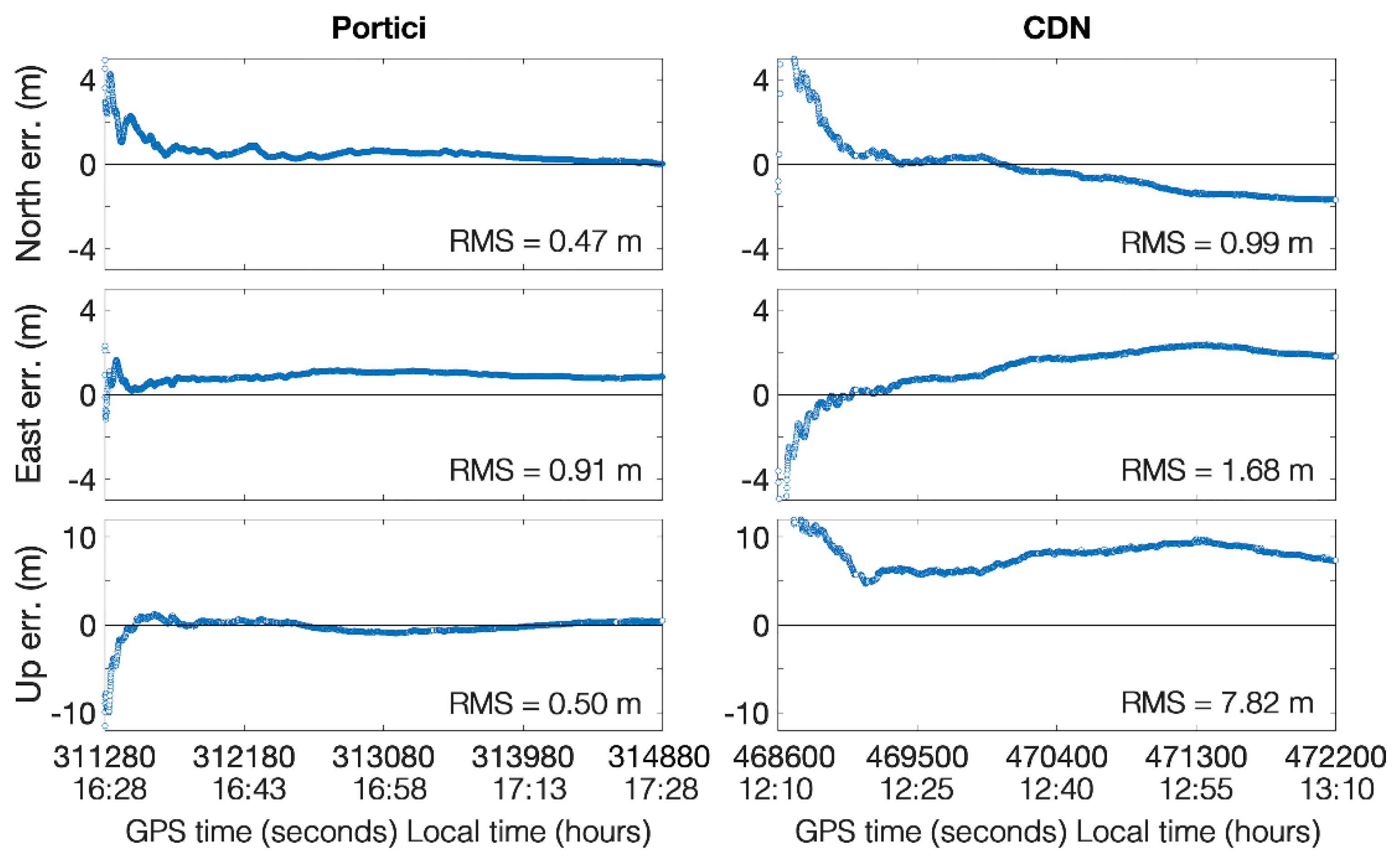
Figure 7 shows the performance of the carrier-based relative positioning in static mode using smartphone as stationary rover for both sites. Due to the smartphone/base station configuration, we get only float solution as only L1 frequency could be used. As expected, performances in the Portici site were better than those in CDN. The RMS for the north and east components for low multipath environment sites were halved compared to the high multipath one. With regard to the RMS of the Up component, it went from 0.50 m in Portici to one of 7.82 to CDN. It should be emphasized that the results obtained are promising as they show that the duty cycle does not damage the phase measurements collected by the Xiaomi Mi 8. As already mentioned, duty cycle makes carrier phase measurements in almost all smartphones useless. Before the advent of the Xiaomi Mi 8, the only smartphone able to achieve position with carrier phase measurements was the Google/HTC Nexus 9 tablet [
7], which has the ability to turn off the duty cycle. Fortunately, the next version of Android OS will make it possible to turn off the duty cycle via software, and this will certainly ensure an increase in the accuracy obtainable with the measures obtained from the smartphone.
In
Table 1, the statistics of the carrier-based and single-point positioning analysis are summarized.
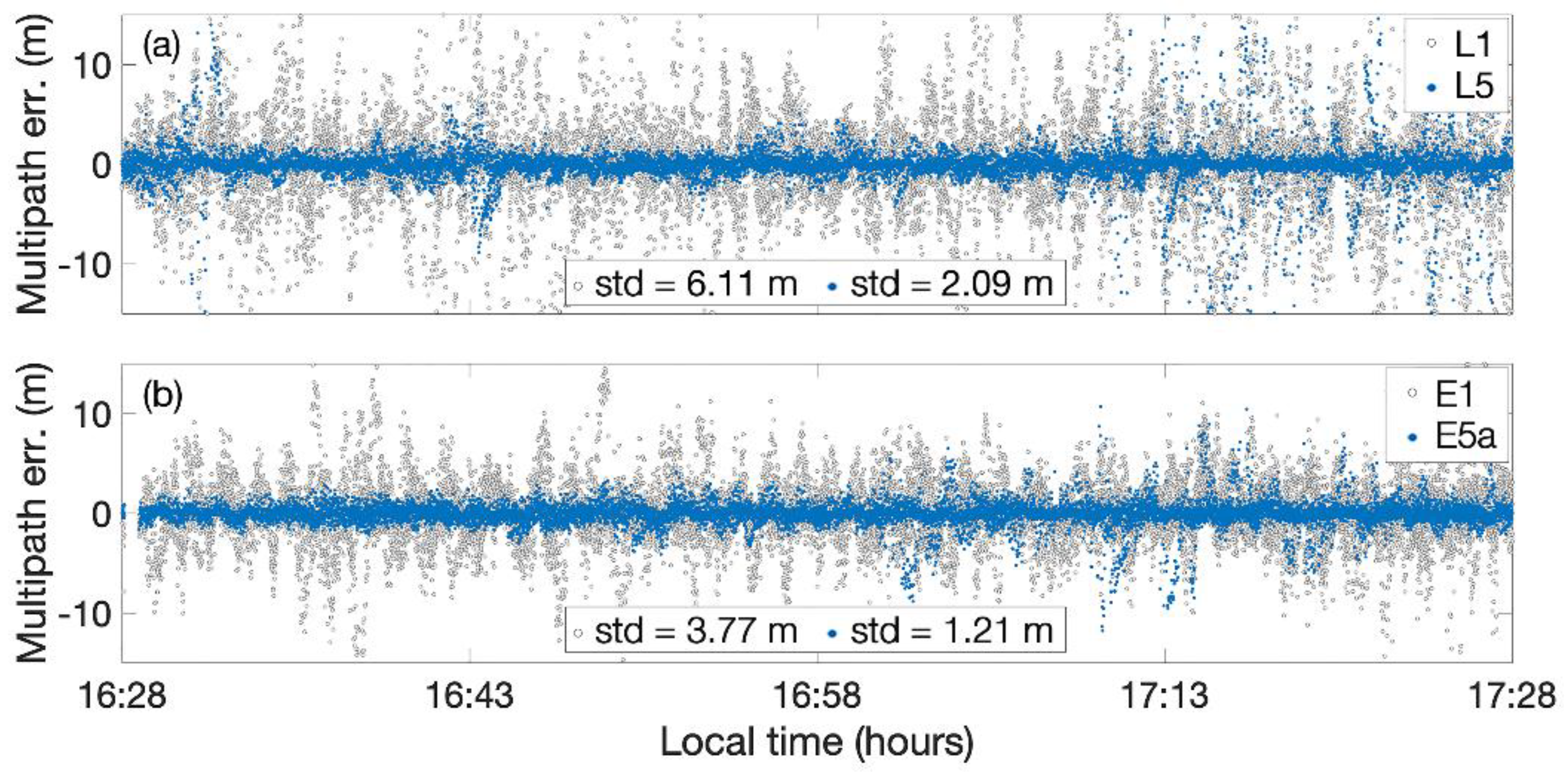
Figure 8 shows the comparison of code multipath between L1/E1 (represented in grey) and L5/E5a (represented in blue) measurements from all the visible GPS (upper panel) and Galileo satellites (lower panel) as whole collected by smartphone in the Portici site versus epoch. Galileo E1 signal shows a code multipath standard deviation of 3.77 m while Galileo E5a multipath error had a standard deviation of 1.21 m. This improvement demonstrates that Galileo E5a signal was specially designed to achieve better performance on multipath. The GPS L1 signal showed a code multipath standard deviation of 6.11 m while the GPS L5 multipath error had a standard deviation of 2.09 m. This improvement demonstrates also in the case of the GPS L5 signal, which appeared to be more effective against multipath as in the case of the Galileo system.
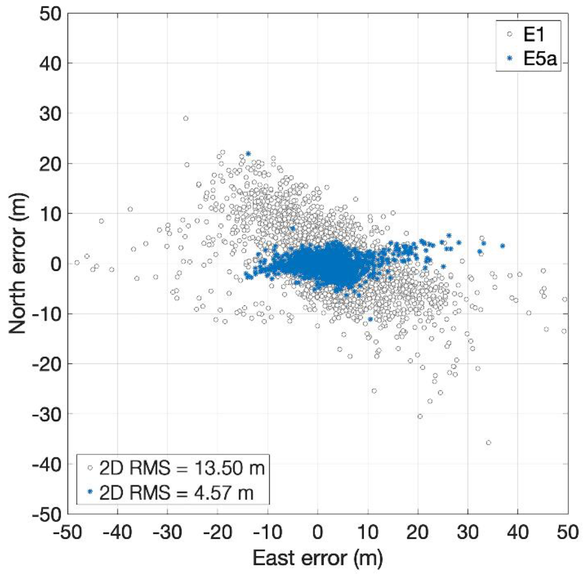
Finally, we conducted an analysis on the Galileo code positioning comparing E1 and E5a signals. This analysis was conducted on a dataset collected in the Portici site as it shows a higher number of visible Galileo satellites with respect to CDN site. The single-point positioning results (
Figure 9) show a horizontal position accuracy of 13.50 m using E1 Galileo measurements with respect to an accuracy of 4.57 m in the case of E5a signal. The results of the vertical component confirm that the E5 signals show a greater accuracy (7.92 m) than those of E1 (34.31 m). This improvement reflects the better multipath performance of the E5a signal with respect to the E1 one confirming that the multipath is one of the dominant sources of error in the code single-point positioning.
5. Discussion
We analyzed and assessed Galileo, GLONASS, and GPS observations from an Android smartphone in terms of C/N0 and code multipath error. The positioning accuracy of static observations in two different sites characterized respectively by low and sever multipath conditions was investigated. Results were compared with those achieved by geodetic receiver. In the following are reported the main observations based on the experiments conducted. First, results related to the analysis of the signal-to-noise ratio are discussed, then those relative to multipath analysis and finally those relative to positioning accuracy achieved:
The C/N0 is lower in the smartphone compared to geodetic receiver in both sites and for all constellations. This is due to the limited performance of the smartphone antenna with respect to a geodetic one. By comparing smartphone L1/E1 carrier-to-noise density with L5/E5a we found that L1/E1 is considerably stronger than L5/E5a for both sites.
A comparison between the GPS and the Galileo smartphone measurements in terms of code multipath error was also made. For both sites, the Galileo measurements show a lower multipath error than the GPS ones. Particularly, an improvement of 25% and 38% was achieved by Galileo measurement in the CDN site and the Portici site, respectively. Despite Galileo improvement, the performance of the smartphone in terms of multipath was still very far from those of the geodetic receiver that showed a decimeter level error. Regarding the analysis of Galileo multipath signals, E5a signals showed a lower code multipath error with respect to E1 ones (as expected) with a standard deviation of 1.21 m with an improvement of 68%.
Regarding positioning domain, several techniques were used (L1 GPS single-point positioning, L1 multi-constellation single-point positioning, E5a Galileo single-point and carrier-based static positioning). The analysis shows that for code positioning (both in L1 GPS only and multi-constellation configuration) the low multipath site has a DRMS (values are reported in
Table 1) that is halved compared to the high multipath site. By using the multi-constellation technique an average improvement of 17% compared to the single GPS approach was achieved. Thus, the multi-constellation is key to improving smartphone single-point positioning. For single point techniques, the best result has been achieved using Galileo E5a measurements collected by smartphone in the Portici site reaching a DRMS of 4.57 m with an improvement of 32% with respect to the L1 GPS only positioning and 15% in respect to the L1/E1 multi-constellation positioning. Finally, we performed carrier phase-based relative positioning in static mode using smartphone as stationary rover for both sites. We get only float positions as only L1 frequency measurements are acquired by both the smartphone and the reference station. The RMS for north, east, and up components in the low multipath site are 0.47 m, 0.91 m, and 0.5 m, respectively.
The results are very promising and were unthinkable until a few months ago. Some interesting related avenues of research that should be pursued include carrier phase real-time kinematic (RTK) positioning using a dual frequency multi-constellation receiver as reference station in conjunction with Xiaomi Mi 8 as rover. The application used to log RINEX data does not support the Beidou system, therefore one of the objectives of future work is to use this satellite system in order to fully exploit the potential of the Xiaomi Mi 8 device. The use of multiple GNSS constellations guarantees the availability of a higher number of satellites, thus a better accuracy positioning could be achieved as showed in the paper. Furthermore, the MIUI 10.1.1 Global Stable for Xiaomi Mi 8 was released in December 2018, namely the first stable international firmware based on Android 9.0 Pie. The new firmware allows the duty cycle to be switched off via software. This ensures better accuracy in phase measurements that should lead to much higher accuracy in the position domain.


