Abstract
In order to effectively extract the frequency characteristics of an underwater acoustic signal under sensor measurement, a fusion frequency feature extraction method for an underwater acoustic signal is presented based on variational mode decomposition (VMD), duffing chaotic oscillator (DCO) and a kind of permutation entropy (PE). Firstly, VMD decomposes the complex multi-component underwater acoustic signal into a set of intrinsic mode functions (IMFs), so as to extract the estimated center frequency of each IMF. Secondly, the frequency of the line spectrum can be obtained by using DCO and a kind of PE (KPE). DCO is used to detect the actual frequency of the line spectrum for each IMF and KPE can determine the accurate frequency when the phase space track is in the great periodic state. Finally, the frequency characteristic parameters acted as the input of the support vector machine (SVM) to distinguish different types of underwater acoustic signals. By comparing with the other three traditional methods for simulation signal and different kinds of underwater acoustic signals, the results show that the proposed method can accurately extract the frequency characteristics and effectively realize the classification and recognition for the underwater acoustic signal.
1. Introduction
Underwater acoustic signal processing is one of the hot topics in the field of marine science. The denoising, feature extraction and classification of underwater acoustic signals are of great significance to the research of underwater acoustic signals, which can provide convenience and basis for the detection and tracking of underwater acoustic signals [1,2,3,4]. Feature extraction methods for underwater acoustic signals mainly include frequency feature extraction, energy feature extraction and complexity feature extraction [5]. The frequency feature extraction method usually consists of three steps: (1) signal processing, (2) feature extraction and (3) classification, among which the first two steps have a great impact on feature extraction. Therefore, we face two challenges: how to select the right signal processing method and how to extract features accurately [6,7].
Traditional time-frequency analysis methods include short-time Fourier transform (STFT), Wigner-Ville distribution (WVD), wavelet transform (WT) and empirical mode decomposition (EMD) [8,9]. However, these methods have certain limitations. For example, the WT need to select wavelet basis functions and wavelet decomposition levels, and EMD has the problem of mode mixing [10]. In recent years, several improved EMD methods have been proposed to suppress mode mixing, which are ensemble EMD (EEMD) [11,12,13,14] and complete EEMD with adaptive noise (CEEMDAN) [15,16,17]. However, EMD and improved EMD methods are all empirical decomposition algorithms, which lack the strict mathematical theory for support [18,19].
Variational mode decomposition (VMD) is a time-frequency analysis method after EMD and improved EMD methods [20]. Compared with EMD and improved EMD methods, VMD decomposes a complex signal into a set of intrinsic mode functions (IMFs) based on a foundation of mature mathematical theories and methods, which are wiener filtering, Hilbert transform, analytic signal and heterodyne demodulation. The sensitivity of VMD to noise is lower than that of EMD and improved EMD methods [21]. VMD has been used in many fields, such as fault diagnosis, clinical medicine and underwater acoustics. In Reference [22], a hybrid fault feature extraction method using VMD combined with multipoint kurtosis was proposed. In Reference [23], focusing on high voltage circuit breakers, a fault diagnosis method using VMD and multi-layer classifier was proposed to improve the accuracy of fault diagnosis. In Reference [24], a new detection method for atrial fibrillation using electrocardiogram signal was proposed, sample entropy and center frequency were extracted from IMFs by VMD, which can effectively distinguish the normal sinus rhythm and atrial fibrillation.
Because the chaotic system is sensitive to a weak signal and immune to noise, it has a wide range of applications in weak signal detection. Duffing system is a kind of common nonlinear system which produces chaotic phenomena. Therefore, duffing chaotic oscillator (DCO) can detect weak signals of low-frequency components. We can detect weak signals in strong background noise by changing the phase space tracks of DCO [25]. Detection of weak signals using DCO has been implemented [26]. In Reference [27], a new weak signal detection method was proposed based on the scale transformation of DCO, which can detect any harmonic signal using a set of determined parameters. In Reference [28], an effective weak signal detection method for underwater acoustic signal was put forward based on DCO and Hilbert transform, which can improve the signal-to-noise ratio greater than the traditional DCO method. The above methods have proved the validity of DCO for weak signal detection.
Permutation entropy (PE) is a method to measure the complexity of time series, which is used in many fields [29,30]. A kind of PE (KPE) was proposed by Bandt in April 2017. KPE, as a novel PE, has better performance than PE in terms of the stability of time series with different lengths [31,32]. Many studies have shown that KPE is superior to PE in medical diagnosis and underwater acoustics.
There are many methods for feature extraction of underwater acoustic signals [33]. Among these methods, the feature extraction methods based on mode decomposition is one of the hot issues of research for underwater acoustic signals. In terms of energy feature extraction of underwater acoustic signals, two methods were put forward using EMD combined with energy entropy and energy spectrum [34,35]. In terms of the complexity of feature extraction of underwater acoustic signals, PE and multi-scale PE (MPE) of IMFs were extracted as new features, where IMFs were obtained by EMD and VMD respectively. Focusing on the frequency feature extraction of underwater acoustic signals, center frequency feature extraction methods were presented using EEMD and VMD. However, these frequency characteristics were not accurate enough.
In the paper, we proposed a new frequency feature extraction method for underwater acoustic signals to effectively extract the frequency characteristics. The proposed method is based on VMD, DCO and KPE. We use VMD to decompose underwater acoustic signals into IMFs. According to the estimated frequency, DCO can detect the frequency of each IMF. When the phase space track is in the great periodic state, we can use KPE to determine the accurate frequency. DCO and KPE are first used to the frequency of IMF for underwater acoustic signals.
The next section is the theory of VMD, DCO and KPE; the novel frequency feature extraction method for underwater acoustic signals is presented in Section 3; the proposed frequency feature extraction method is used to simulate signals and underwater acoustic signals in Section 4 and Section 5; and, finally, the concluding remarks are made in the last section.
2. Theory
2.1. VMD
The VMD theory consists of two parts: the constrained variational problem and specific steps to solve. VMD defines the amplitude-modulated-frequency-modulated signal as IMF, which is shown in Equation (1).
where is the -th IMF by VMD, and are the envelope and phase of the -th IMF. Each IMF has estimated frequency and limited bandwidth. The constrained variational problem is shown in Equation (2).
where represents the un-decomposed complex signal, and represent the number of and estimated frequency for the -th IMF. The solved non-constrained variational problem is shown in Equation (3).
where is the augmented Lagrangian method, and are the penalty factor and Lagrange multiplier. We use the alternating direction multiplier method to get saddle points and update , and . These updated formulas are shown in Equation (4).
where represents the frequency domain. The flow diagram of VMD is given in Figure 1. More detailed explanations about VMD can be found [20,21].
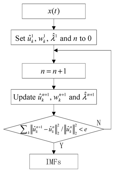
Figure 1.
The flow diagram of VMD.
2.2. DCO
The normal form of a duffing chaotic oscillator (DCO) equation is shown in Equation (5).
where is the damping ratio, and represent the nonlinear resilience item and the driving force. When equals , DCO equation can be expressed in Equation (6).
and represent the angular frequency and amplitude of the driving force. Due to the existence of the nonlinear resilience item, the DCO equation is rich in nonlinear dynamic characteristics. We make increase from 0 while fixing , the system state changes from homoclinic orbits state to bifurcation state, and then when the threshold is exceeded, the system state changes from chaos state to the great periodic motion. The steps of periodic signal detection by DCO are as follows:
- (1)
- Put periodic signal and noise signal into the system, DCO equation can be expressed in Equation (7).
- (2)
- Set , and to 0.5, 0 and 0. The Runge-Kutta of the fourth order is used for a solution of DCO equation.
- (3)
- We can determine whether the angular frequency of the periodic signal is close to according to the system state. When the system state is the great periodic state, this means that the angular frequency of the periodic signal is approximated as , and vice versa. More detailed explanations about DCO can be found elsewhere [27,28].
2.3. KPE
In order to better understand KPE, we learn KPE by comparing with PE. Both PE and KPE can represent the complexity of time series. However, they have the following differences:
- (1)
- KPE, as an improved PE, is defined as the distance between the time series and white Gaussian noise. Therefore, KPE and PE have a totally opposite trend. For example, when the time series is white Gaussian noise, PE and KPE are close to 1 and 0 respectively.
- (2)
- The equations of KPE and PE are different. KPE and PE can be expressed aswhere and represent KPE and PE, and are the number of reconstructed vectors and the embedded dimension, represents -th probability of symbol sequence.
- (3)
- Compared with PE, KPE has better robustness for time series of different lengths.
More details of PE and KPE can be found elsewhere [29,30,31,32].
3. Frequency Feature Extraction Method for Underwater Acoustic Signal
This paper presents a fusion frequency feature extraction method for underwater acoustic signal based on VMD, DCO and KPE. The flow chart of the feature extraction method is shown in Figure 2. The experimental steps of this frequency feature extraction method are as follows:
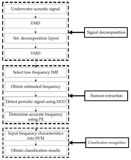
Figure 2.
The flow chart of a fusion frequency feature extraction method.
- Step 1:
- Signal decomposition.
- (1)
- Collect underwater acoustic signals by sensors;
- (2)
- Decompose underwater acoustic signals by EMD, M IMFs can be obtained;
- (3)
- Set the decomposition layers of VMD to M;
- (4)
- Decompose underwater acoustic signals by VMD.
- Step 2:
- Feature extraction.
- (1)
- Select the low-frequency IMF for the research, such as the last IMF;
- (2)
- Obtain estimated frequency of selected IMF by VMD;
- (3)
- Detect periodic signal of selected IMF using DCO;
- (4)
- When the phase track of selected IMF is in great periodic, and the KPE of DCO system output reaches the maximum, we can determine the accurate frequency of selected IMF.
- Step 3:
- Classification recognition.
- (1)
- Input frequency characteristics of different kinds of underwater acoustic signals into SVM;
- (2)
- Obtain classification results of different kinds of underwater acoustic signals.
4. Frequency Feature Extraction for Simulation Signal
To prove the reliability of this fusion frequency feature extraction method, we extract the frequency feature for the simulation signal. First, the simulation signal is decomposed by VMD. Secondly, the periodic signal of IMFs can be detected by DCO, frequency characteristics of IMFs can be obtained by KPE. Finally, we compared with three frequency feature extraction methods presented recently.
4.1. VMD of Simulation Signal
Line spectrums of ship-radiated noise can reflect an important frequency feature, and the line spectrum corresponds to the periodic signal in the time domain. Therefore, the clear signal consists of three cosine signals with different amplitudes and frequencies, and the noisy signal consists of both the clear signal and the standard Gaussian white noise . The specific simulation signals are as follows:
The frequencies of three cosine signals are 10 Hz, 50 Hz and 100 Hz, respectively. The sampling frequency is 1 kHz. The time-domain waveforms of both clear and noisy signal are shown in Figure 3. According to the EMD result for noisy signals, we set the decomposition layers of VMD to 9, the VMD result for noisy signals is shown in Figure 4. As seen in Figure 3, the clear signal is submerged in noise. As seen in Figure 4, the order of IMFs by VMD is from high frequency to low frequency. Each IMF has an estimated frequency, the frequency distribution of IMFs by VMD is listed in Table 1. As can be seen in Table 1, IMF9, IMF8 and IMF7 correspond to the cosine signal with the frequency of 10 Hz, 50 Hz and 100 Hz, respectively.
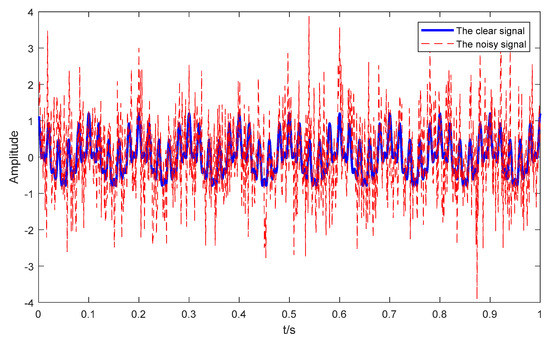
Figure 3.
The time-domain waveforms of both the clear and noisy signals.
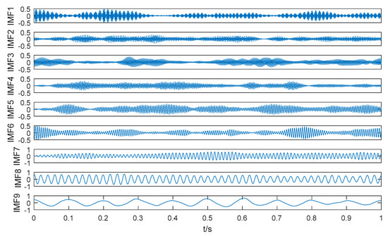
Figure 4.
The VMD result for the noisy signal.

Table 1.
The frequency distribution of IMFs by VMD.
4.2. Frequency Feature Extraction of IMF Using DCO and KPE
According to the estimated frequency of IMFs, the three periodic signals are in the last three IMFs, and the other IMFs are noise IMFs without periodic signals. Therefore, we extract the frequency features of the last three IMFs using DCO and KPE, respectively.
4.2.1. Frequency Feature Extraction of IMF9
The estimated frequency of IMF9 is 10.14 Hz. A DCO column is used to sweep through the true frequency, and the driving force frequency is close to 10.14 Hz. A DCO column consists of 10 DCOs, frequency interval of each DCO is 0.01 KHz. The phase space tracks of different driving force frequencies are shown in Figure 5. As seen in Figure 5, when the driving force frequencies are 9.74 Hz and 10.24 Hz, the phase space tracks are in chaos state; when the driving force frequencies are 9.94 Hz and 10.04 Hz, the phase space tracks are in the great periodic state.
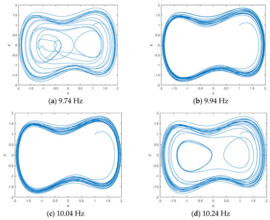
Figure 5.
The phase space tracks of different driving force frequencies for IMF9.
When the phase space track is in the great periodic state, we calculated the KPE of the DCO system output under different driving force frequencies. The KPE distribution of IMF9 under different driving force frequencies is listed in Table 2. As can be seen in Table 2, when the driving force frequency is 9.98 Hz, the KPE reaches the maximum. Therefore, the frequency feature of IMF9 is 9.98 Hz using the proposed frequency feature extraction method.

Table 2.
The KPE distribution of IMF9 under different driving force frequencies.
4.2.2. Frequency Feature Extraction of IMF8 and IMF7
The estimated frequencies of IMF8 and IMF7 are 50.12 Hz and 99.47 Hz. Two DCO columns were used to sweep through the true frequency of IMF8 and IMF7 according to the estimated frequencies. The phase space tracks of different driving force frequencies for IMF8 and IMF7 are shown in Figure 6 and Figure 7. As seen in Figure 6, when the driving force frequencies are 49.82 Hz and 50.22 Hz, the phase space tracks are in the chaos state, and when the driving force frequencies are 49.92 Hz and 50.12 Hz, the phase space tracks are in the great periodic state. As seen in Figure 7, when the driving force frequencies are 99.47 Hz and 100.17 Hz, the phase space tracks are in the chaos state, and when the driving force frequencies are 99.97 Hz and 100.07 Hz, the phase space tracks are in the great periodic state.
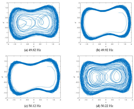
Figure 6.
The phase space tracks of different driving force frequencies for IMF8.
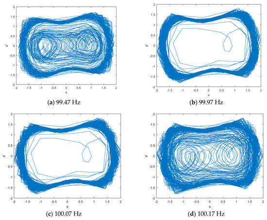
Figure 7.
The phase space tracks of different driving force frequencies for IMF7.
When the phase space tracks of IMF8 and IMF7 were in the great periodic state, we calculated the KPE of the DCO system output under different driving force frequencies. The KPE distributions of IMF8 and IMF7 under different driving force frequencies are listed in Table 3 and Table 4. As can be seen in Table 3 and Table 4, when the driving force frequency of IMF8 and IMF7 are 49.99 Hz and 100.03 Hz, the KPEs reach the maximum. Therefore, the frequency features of IMF8 and IMF7 are 49.99 Hz and 100.03 Hz.

Table 3.
The KPE distribution of IMF8 under different driving force frequencies.

Table 4.
The KPE distribution of IMF7 under different driving force frequencies.
4.3. Comparison of Different Frequency Feature Extraction Methods
In order to further prove the reliability of this fusion frequency feature extraction method, we compare the results of four different frequency feature extraction methods. The frequency feature extraction methods using different mode decomposition and center frequency are named as EMD-CF, EEMD-CF and VMD-CF, and the proposed frequency feature extraction method is called VMD-DCO-KPE. Frequency features are statistical center frequencies in EMD-CF, EEMD-CF and VMD-CF, and frequency feature is line spectrum frequencies in VMD-DCO-KPE. The EMD and EEMD results for noisy signals are shown in Figure 8. As seen in Figure 8, the number of IMFs are different between EMD and EEMD. The frequency distributions of IMFs by EMD and EEMD are listed in Table 5 and Table 6. As can be seen in Table 5 and Table 6, IMF6, IMF4 and IMF3 correspond to cosine signal with the frequency of 10 Hz, 50 Hz and 100 Hz, respectively. Frequency features by different frequency feature extraction methods are listed in Table 7. As can be seen in Table 7, the proposed VMD-DCO-KPE method is the closest to the true frequency.
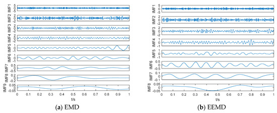
Figure 8.
The EMD and EEMD results for noisy signal.

Table 5.
The frequency distribution of IMFs by EMD.

Table 6.
The frequency distribution of IMFs by EEMD.

Table 7.
Frequency features by different frequency feature extraction methods.
5. Application in Underwater Acoustic Signals
Firstly, three kinds of underwater acoustic signals were decomposed by VMD; then, the frequency features were extracted using the VMD-DCO-KPE method; finally, the frequency feature and classification results of the different methods were compared.
5.1. VMD of Ship-Radiated Noise Signal
Ship-radiated noise is an important part of underwater acoustic signals. In this paper, three kinds of ship-radiated noise samples were selected for frequency feature extraction, namely ship 1, ship 2 and ship 3. Their sampling frequency and sampling points were 44.1 kHz and 2000. Figure 9 depicts a 3D underwater acoustic signal measurement. The depth of the measurement area was about 4 km, and the topography of the seabed was fairly flat. In order to degrade the influence of ocean environmental noise, we measured data at the level 1 sea state by using omnidirectional hydrophones. The research ship carried hydrophones with a depth of 30 m and was not in service during the whole measurement process. The distance between the research ship and the target ship (Ship 1, Ship 2 and Ship 3) was about 2.5 km. When one of the target ships was running, the other ships remained out of work.
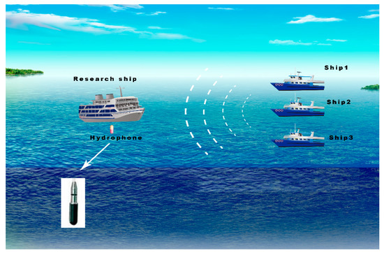
Figure 9.
3D underwater acoustic signal measurement.
The normalized time-domain waveform for three kinds of ship-radiated noise samples is shown in Figure 10. The VMD results of ship-radiated noise samples are shown in Figure 11. As seen in Figure 11, the IMFs of three kinds of ship-radiated noise samples were recorded in descending order of frequency, and the IMF of the lowest frequency is IMF8.
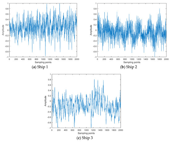
Figure 10.
The normalized time-domain waveform for three kinds of ship-radiated noise samples.
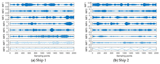
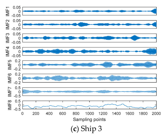
Figure 11.
The VMD results of ship-radiated noise samples.
5.2. Frequency Feature Extraction of Line Spectrum
The line spectrums of ship-radiated noise can reflect the important physical characteristics of ships, and line spectrums usually exist in the low frequency of ships. In this paper, we selected the line spectrum of IMF8 as the frequency feature of ship-radiated noise. The frequency distribution of IMF8 by VMD for three kinds of ship-radiated noise samples are listed in Table 8. According to the estimated frequency by VMD, a DCO column is used to sweep through the true frequency. The great periodic states of IMF8 for three kinds of ship-radiated noise samples are shown in Figure 12. When the phase space track is in the great periodic state, we calculated the KPE and obtained the true frequency by using the maximum value of KPE. The frequency distribution of IMF8 by VMD-DCO-KPE for three kinds of ship-radiated noise samples is listed in Table 9.

Table 8.
The frequency distribution of IMF8 by VMD for three kinds of ship-radiated noise samples.
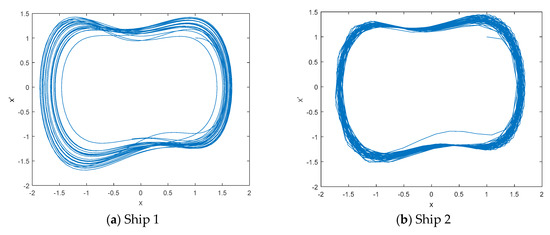
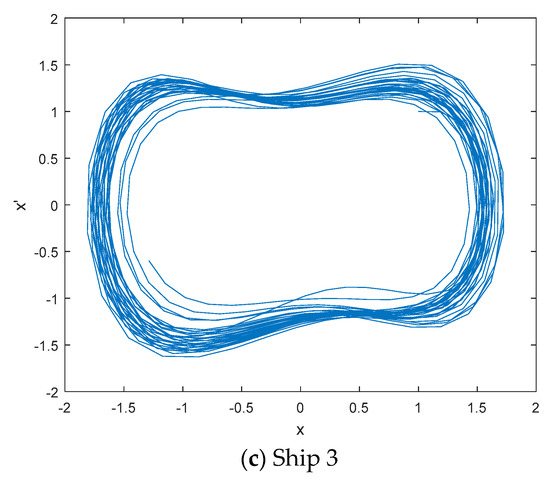
Figure 12.
The great periodic states of IMF8 for three kinds of ship-radiated noise samples.

Table 9.
The frequency distribution of IMF8 by VMD-DCO-KPE for three kinds of ship-radiated noise samples.
5.3. Comparison of Different Frequency Feature Extraction Methods
We extracted the frequency features of 20 samples for each kind of ship. The frequency distributions of VMD-DCO-KPE and VMD-CF are shown in Figure 13. In order to prove the effectiveness of VMD-DCO-KPE, SVM with polynomial kernel function was used for the classification of three kinds of ships. The number of training samples and test samples were 20 and 30, and the classification results of different frequency feature extraction methods are listed in Table 10. As shown in Table 10, the classification result of VMD-DCO-KPE was 100%, which is better than EMD-CF, EEMD-CF and VMD-CF.
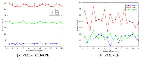
Figure 13.
The frequency distributions of VMD-DCO-KPE and VMD-CF.

Table 10.
The classification results of different frequency feature extraction methods.
6. Conclusions
A novel frequency feature extraction method for underwater acoustic signal is proposed in this paper based on VMD, DCO and KPE. The main contributions of this work are as follows:
- (1)
- DCO is first used to detect the frequency of IMF by VMD for underwater acoustic signals in this paper.
- (2)
- KPE is first used to determine the frequency of IMF combined with DCO for underwater acoustic signals in this paper.
- (3)
- VMD-DCO-PE is successfully applied to extract the frequency feature of a simulation signal. Compared with EMD-CF, EEMD-CF and VMD-CF, VMD-DCO-KPE can be more accurate and efficient to extract the frequency feature of a simulation signal.
- (4)
- VMD-DCO-KPE is also applied to extract the frequency feature extraction of line spectrum for underwater acoustic signal. VMD-DCO-KPE has better classification performance than EMD-CF, EEMD-CF and VMD-CF.
Author Contributions
Y.L. contributed the frequency feature extraction method, all authors designed and analyzed the experiments.
Funding
Authors gratefully acknowledge the support by National Natural Science Foundation of China (No. 51409214 and No. 11574250).
Conflicts of Interest
The authors declare no conflicts of interest.
References
- Urick, R.J. Principles of Underwater Sound, 3rd ed.; McGraw-Hill: New York, NY, USA, 1983. [Google Scholar]
- Li, Y.; Li, Y.; Chen, X.; Yu, J. A Novel Feature Extraction Method for Ship-Radiated Noise Based on Variational Mode Decomposition and Multi-Scale Permutation Entropy. Entropy 2017, 19, 342. [Google Scholar] [CrossRef]
- Li, Y.; Li, Y.; Chen, X.; Yu, J. Research on Ship-Radiated Noise Denoising Using Secondary Variational Mode Decomposition and Correlation Coefficient. Sensors 2018, 18, 48. [Google Scholar] [CrossRef]
- Villecco, F. On the Evaluation of Errors in the Virtual Design of Mechanical Systems. Machines 2018, 6, 36. [Google Scholar] [CrossRef]
- Wang, S.; Zeng, X. Robust underwater noise targets classification using auditory inspired time-frequencyanalysis. Appl. Acoust. 2014, 78, 68–76. [Google Scholar] [CrossRef]
- Xu, L.; Yang, K.; Yang, Q. Joint time-frequency inversion for seabed properties of ship noise on a vertical line array in South China Sea. IEEE Access 2018, 6, 62856–62864. [Google Scholar] [CrossRef]
- Gassmann, M.; Wiggins, S.M.; Hildebrand, J.A. Deep-water measurements of container ship radiated noise signatures and directionality. J. Acoust. Soc. Am. 2017, 142, 1563. [Google Scholar] [CrossRef] [PubMed]
- Wang, Y.H.; Hu, K.; Lo, M.T. Uniform phase empirical mode decomposition: An optimal hybridization of masking signal and ensemble approaches. IEEE Access 2018, 6, 34819–34833. [Google Scholar] [CrossRef]
- Wang, J.L.; Wei, Q.X.; Zhao, L.Q.; Yu, T.; Han, R. An improved empirical mode decomposition method using second generation wavelets interpolation. Digit. Signal Process. 2018, 79, 164–174. [Google Scholar] [CrossRef]
- Chen, T.; Ju, S.; Yuan, X.; Elhoseny, M.; Ren, F.; Fan, M.; Chen, Z. Emotion recognition using empirical mode decomposition and approximation entropy. Comput. Electr. Eng. 2018, 72, 383–392. [Google Scholar] [CrossRef]
- Zhang, X.; Liang, Y.; Zhou, J.; Zhou, J.; Zang, Y. A novel bearing fault diagnosis model integrated permutation entropy, ensemble empirical mode decomposition and optimized SVM. Measurement 2015, 69, 164–179. [Google Scholar] [CrossRef]
- Chu, H.; Wei, J.; Qiu, J. Monthly Streamflow Forecasting Using EEMD-Lasso-DBN Method Based on Multi-Scale Predictors Selection. Water 2018, 10, 1486. [Google Scholar] [CrossRef]
- Huang, Y.; Liu, S.; Yang, L. Wind Speed Forecasting Method Using EEMD and the Combination Forecasting Method Based on GPR and LSTM. Sustainability 2018, 10, 3693. [Google Scholar] [CrossRef]
- Singh, J.; Darpe, A.K.; Singh, S.P. Bearing damage assessment using Jensen-Rényi Divergence based on EEMD. Mech. Syst. Signal Process. 2017, 87, 307–339. [Google Scholar] [CrossRef]
- Yeh, J.R.; Shieh, J.S.; Huang, N.E. Complementary ensemble empirical mode decomposition: A novel noise enhanced data analysis method. Adv. Adapt. Data Anal. 2010, 2, 135–156. [Google Scholar] [CrossRef]
- Liu, H.; Mi, X.W.; Li, Y.F. Comparison of two new intelligent wind speed forecasting approaches based on Wavelet packet decomposition, complete ensemble empirical mode decomposition with adaptive noise and artificial neural networks. Energ. Conv. Manag. 2018, 155, 188. [Google Scholar] [CrossRef]
- Lv, Y.; Yuan, R.; Wang, T.; Li, H.; Song, G. Health Degradation Monitoring and Early Fault Diagnosis of a Rolling Bearing Based on CEEMDAN and Improved MMSE. Materials 2018, 11, 1009. [Google Scholar] [CrossRef]
- Dai, S.; Niu, D.; Li, Y. Daily Peak Load Forecasting Based on Complete Ensemble Empirical Mode Decomposition with Adaptive Noise and Support Vector Machine Optimized by Modified Grey Wolf Optimization Algorithm. Energies 2018, 11, 163. [Google Scholar] [CrossRef]
- Bin Queyam, A.; Kumar Pahuja, S.; Singh, D. Quantification of Feto-Maternal Heart Rate from Abdominal ECG Signal Using Empirical Mode Decomposition for Heart Rate Variability Analysis. Technologies 2017, 5, 68. [Google Scholar] [CrossRef]
- Dragomiretskiy, K.; Zosso, D. Variational mode decomposition. IEEE Trans. Signal Process. 2014, 62, 531–544. [Google Scholar] [CrossRef]
- Li, Y.; Li, Y.; Chen, X.; Yu, J. Denoising and Feature Extraction Algorithms Using NPE Combined with VMD and Their Applications in Ship-Radiated Noise. Symmetry 2017, 9, 256. [Google Scholar] [CrossRef]
- Cai, W.; Yang, Z.; Wang, Z.; Wang, Y. A New Compound Fault Feature Extraction Method Based on Multipoint Kurtosis and Variational Mode Decomposition. Entropy 2018, 20, 521. [Google Scholar] [CrossRef]
- Wan, S.; Chen, L.; Dou, L.; Zhou, J. Mechanical Fault Diagnosis of HVCBs Based on Multi-Feature Entropy Fusion and Hybrid Classifier. Entropy 2018, 20, 847. [Google Scholar] [CrossRef]
- Tripathy, R.K.; Paternina, M.R.A.; Arrieta, J.G.; Pattanaik, P. Automateddetection of atrialfibrillation ECG signalsusing twostage VMD and atrialfibrillation diagnosis index. J. Mech. Med. Biol. 2017, 17, 840–844. [Google Scholar] [CrossRef]
- Wang, G.; Chen, D.; Lin, J.; Chen, X. The application of chaotic oscillators to weak signal detection. IEEE Trans. Ind. Electron. 1999, 46, 440–444. [Google Scholar] [CrossRef]
- Li, Y.; Shi, Y.; Ma, H.; Yang, B. Chaotic detection method for weak square wave signal submerged in colored noise. Chin. J. Electron. 2004, 32, 87–90. [Google Scholar]
- Lai, Z.; Leng, Y.; Sun, J.; Fan, B. Weak characteristic signal detection based on scale transformation of Duffing oscillator. Acta Phys. Sin. 2012, 61, 050503. [Google Scholar]
- Chen, Z.; Li, Y.; Chen, X. Underwater acoustic weak signal detection based on Hilbert transform and intermittent chaos. Acta Phys. Sin. 2015, 64, 200502. [Google Scholar]
- Bandt, C.; Pompe, B. Permutation entropy: A natural complexity measure for time series. Phys. Rev. Lett. 2002, 88, 174102. [Google Scholar] [CrossRef]
- Zhang, J.; Hou, G.; Cao, K.; Ma, B. Operation conditions monitoring of flood discharge structure based on variance dedication rate and permutation entropy. Nonlinear Dyn. 2018, 93, 1–15. [Google Scholar] [CrossRef]
- Bandt, C. A new kind of permutation entropy used to classify sleep stages from invisible EEG microstructure. Entropy 2017, 19, 197. [Google Scholar] [CrossRef]
- Haruna, T. Partially ordered permutation complexity of coupled time series. Phys. D Nonlinear Phenom. 2018, 388, 40–44. [Google Scholar] [CrossRef]
- Hu, Q.; Hao, B.; Lv, L. Feature extraction model for underwater target radiated noise. Torpedo Technol. 2008, 16, 38. [Google Scholar]
- Liu, S.; Zhang, X.; Niu, Y. Feature extraction and classification experiment of underwater acoustic signals based on energy spectrum of IMF’s. Comput. Eng. Appl. 2014, 50, 203–206. [Google Scholar]
- Yang, H.; Li, Y.; Li, G. Energy analysis of ship-radiated noise based on ensemble empirical mode decomposition. J. Vib. Shock 2015, 34, 55–59. [Google Scholar]
© 2019 by the authors. Licensee MDPI, Basel, Switzerland. This article is an open access article distributed under the terms and conditions of the Creative Commons Attribution (CC BY) license (http://creativecommons.org/licenses/by/4.0/).