Article

Coordination of Congestion and Awareness Control in Vehicular Networks

UWICORE Laboratory, Universidad Miguel Hernández de Elche (UMH), Avda. de la Universidad s/n, 03202 Elche, Spain
*
Author to whom correspondence should be addressed.
Electronics 2018, 7(11), 335; https://doi.org/10.3390/electronics7110335
Submission received: 26 October 2018 / Revised: 14 November 2018 / Accepted: 15 November 2018 / Published: 20 November 2018
(This article belongs to the Special Issue Smart, Connected and Efficient Transportation Systems)

Abstract

:
Vehicular networks need to guarantee the communication reliability levels necessary to satisfy the application requirements, while ensuring a stable network operation even under dense deployments. To this aim, congestion and awareness control protocols dynamically adapt the same communication parameters based on context conditions. If the two protocols operate independently, negative interactions or conflicts can arise. This situation can occur if for example congestion control requires decreasing the transmission power to reduce the channel load, but this reduction negatively influences the vehicles’ awareness range. To address these interactions or conflicts, this paper proposes and evaluates a methodology to coordinate congestion and awareness control protocols. A key advantage of the proposed methodology is that it does not require the integration of the interacting protocols, nor does it require changing their original design. The obtained results demonstrate the effectiveness of the proposed coordination methodology. In addition, the proposed methodology can be extended to the coordination of multiple protocols operating over the same communication parameters. This is here demonstrated considering the coordination of congestion, awareness and topology control protocols.

1. Introduction

Vehicular networks require the exchange of positioning and basic vehicular status information between neighboring nodes. Such exchange is based on the periodic transmission/reception of 1-hop broadcast messages on the so-called control channel [1]. The critical nature of this reference channel has fostered significant efforts in the research and standardization communities to design congestion control schemes that adapt the communication parameters to ensure the scalability and adequate operation of vehicular networks [2,3]. For example, the ETSI ITS Communications architecture [4] includes a Decentralized Congestion Control (DCC) functionality with several components distributed over different layers of the protocol stack (Figure 1). One key component is DCC_CROSS [5]. DCC_CROSS runs the core of the DCC algorithm and adjusts the communication parameters based on metrics received from the other DCC components using a reactive state-based and linear adaptive approach. The DCC_ACC [6] component measures the local channel load and restricts the access to the channel based on the output from the DCC algorithm. The DCC_NET [7] component disseminates the local DCC parameters to other vehicles. Finally, the DCC_FAC [8] component controls the packet generation rate, packet priorities and re-broadcasts based on the output received from the DCC algorithm.
Most congestion control algorithms are based on the dynamic adaptation of the packet transmission frequency and/or power to control the channel load and provide fair and harmonized access to the wireless medium. These communication parameters are also critical for other protocols, and it is therefore necessary to carefully consider their impact. For example, awareness control protocols [9] seek to ensure each vehicle’s capacity to detect, and possibly communicate with the relevant vehicles and infrastructure nodes present in their local neighborhood. To this aim, awareness control protocols must adapt the communication parameters to guarantee the necessary communications or awareness range [10,11]. It is possible that if a congestion control protocol reduces the packet transmission frequency or power to decrease the channel load, the resulting transmission frequency or power does not meet the latency or communications range requirements of a particular application. This scenario is illustrated in the example depicted in Figure 2. The high density of vehicles in the congested road segment would require the use of congestion control protocols to control and limit the channel load. These protocols would, for example, reduce the transmission power or packet transmission frequency to all vehicles in the scenario in order to reduce the channel load and ensure the networks’ stability. However, the communication parameters cannot be modified equally to all vehicles since their application requirements are different as a result of the different speeds and distances to neighboring vehicles. Vehicles under free-flow conditions require a communications range sufficiently large to allow for a safe lane-change maneuver for example. Reducing their transmission power would hence negatively affect their capacity to satisfy their application requirements. On the other hand, the communications range for vehicles in the traffic jam direction can be notably reduced as a result of their limited mobility. Vehicles in the traffic jam could hence reduce their transmission power without negatively affecting their application requirements. This example clearly shows the need for an application- and context-centric design of vehicular networks, and a careful coordination of congestion and awareness control.
The adaptation of communication parameters can also influence the operation and performance of other protocols. For example, reducing the transmission power to control the channel load can also change the network topology, decrease the number of connected neighboring vehicles, and thereby influence the operation of topology control protocols [12]. Different protocols can operate over the same parameters and can provide contrary instructions regarding the configuration of such parameters. The interactions among protocols can provoke unintended and negative adaptation loops [13] that reduce the network performance and the applications’ effectiveness (defined as the capacity to satisfactorily meet the vehicles’ application requirements). It is therefore critical that protocols are designed considering their direct or indirect interactions. To do so, one methodology is the integration of interacting protocols. The integration methodology can lead to short-term performance gains because the integrated solution must be specifically designed for the protocols that are integrated. However, it also has non-negligible disadvantages that motivated this study:
  • Constrained evolution. With the integration methodology, the evolution of a system or standard will be constrained, and possibly limited by the adopted integrated solution. This is the case because any evolution of the interacting protocols would require a revision of the design of the integrated solution.
  • Tailored designs. Different integrated solutions will be needed based on the protocols that are being integrated. The integration of different protocols requires different designs that are specific for the protocols to be integrated [14].
  • Limited modularity. The integration methodology does not fully preserve the modularity of the layered protocol stack. Interacting protocols are integrated in a novel solution that does not follow modular design guidelines. Enabling cross-layer interactions while preserving modularity is a challenge still to be solved [15,16].
  • Coexistence. It is not easy to integrate two different cross-layer protocols. There is no widely accepted cross-layer design coexistence methodology [13,14].
This study is motivated by the limitations that have just been described, and that result from trying to solve conflicts between interacting protocols through their integration. To tackle these limitations, this paper proposes an alternative methodology for the cross-layer coordination of interacting protocols that can simultaneously coexist and operate in vehicular networks. The proposed methodology (COMPASS, cross-layer coordination of multiple vehicular protocols) solves negative interactions between protocols that operate over the same communication parameters by coordinating their operation rather than integrating them. COMPASS has been initially designed as a means to coordinate congestion and awareness control protocols in vehicular networks. However, this study will also demonstrate that COMPASS can coordinate other interacting protocols. In particular, this study considers the coexistence of congestion, awareness, and topology control. This paper will also demonstrate that COMPASS has a very low computational complexity.
Figure 3 conceptually illustrates the difference between the integrated and coordinated (i.e., COMPASS) methodologies. The figure considers two protocols that adapt communication parameters p1 and p2 at the same or different layers of the protocol stack. When operating independently, a conflict situation can occur if the protocols require different settings for p1 and p2 to achieve their respective objectives (Figure 3a). The problem can be solved by designing a solution that integrates the two conflicting protocols, and results in a configuration for the p1 and p2 parameters that satisfies the two original protocols (Figure 3b). On the other hand, the proposed COMPASS methodology does not require modifying the original protocols (Figure 3c). Instead, it receives as input their configuration requests, and selects a configuration of the p1 and p2 parameters that is suitable to both protocols. The integrated methodology depends on the specific details and implementations of the protocols. This is not the case of the coordinated methodology since it does not require the modification of the protocols it tries coordinating. COMPASS can hence coordinate the operation of a varying number of protocols without the need for a new re-design every time an additional protocol needs to be taken into account or be removed from the stack. COMPASS can be implemented within the transversal Management layer defined by ETSI [4] or the CALM Management entity defined by ISO TC204 [17]. From the Management layer, COMPASS has access to all the metrics collected by the different layers (e.g., the channel load or the number of neighboring vehicles) and can configure parameters at different layers (e.g., the transmission power and packet transmission frequency). The advantages of COMPASS compared with existing solutions can be summarized as:
  • COMPASS solves conflicts between protocols that operate independently over the same communication parameters. Such conflicts can occur, for example, when two different protocols request contradictory changes to a given transmission parameter.
  • COMPASS can solve these conflicts by coordinating the operation of different protocols operating over the same communication parameters. Such coordination does not require the integration of these protocols or their re-design, which facilitates the future evolution of vehicular networks and the coexistence with legacy solutions.
  • COMPASS is not restricted to a set or number of protocols. COMPASS can coordinate the operation of a varying number of protocols (acting over the same communication parameters), and this number can change over time. This again increases the impact of COMPASS and the future evolution of vehicular networks.
  • COMPASS can achieve similar performance levels to that achieved by integrating the conflicting protocols, with the added benefits of an easier evolution of vehicular networks and the coexistence with legacy solutions.
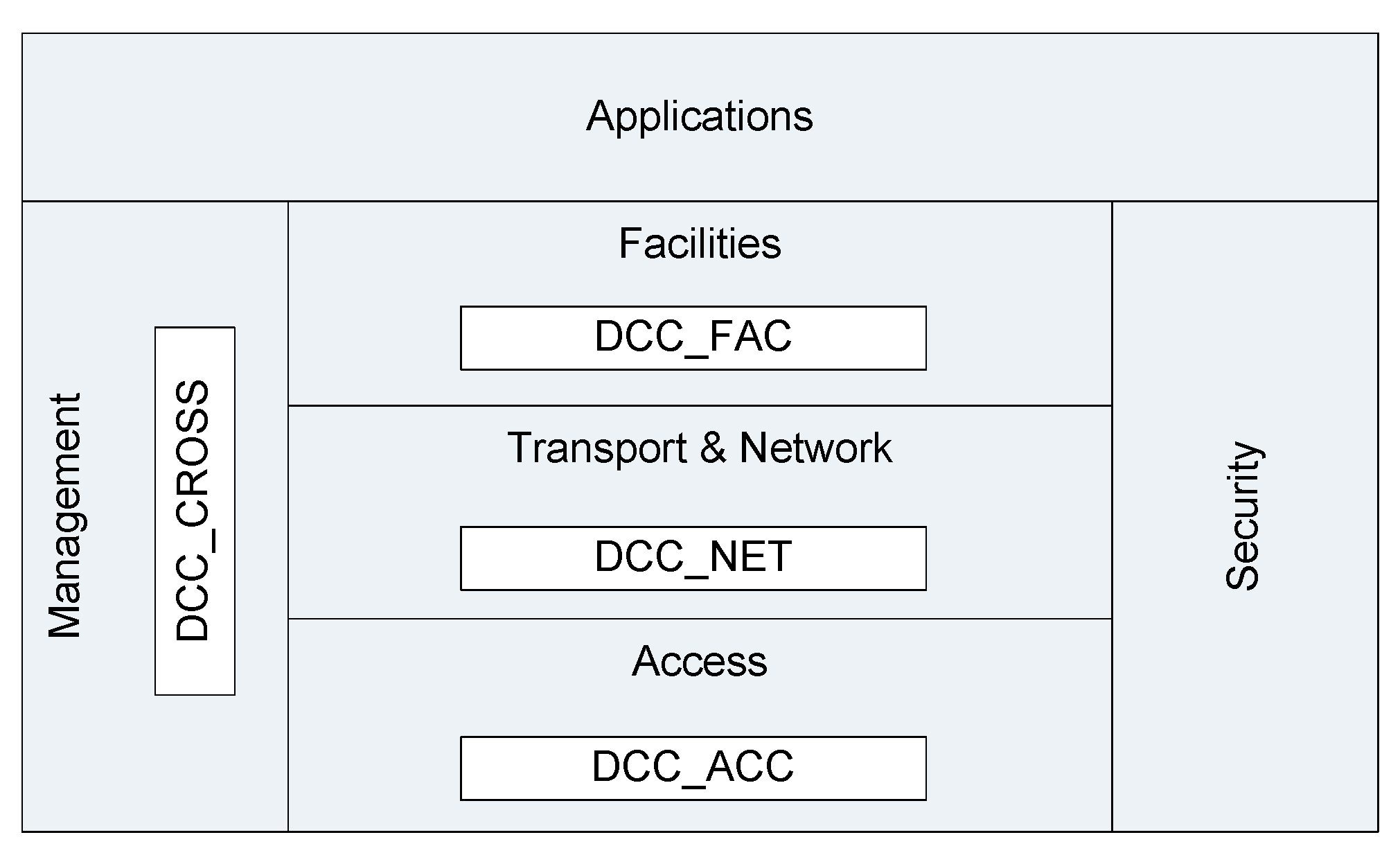
  • COMPASS has been designed so that it can be easily integrated into the transversal Management layers of the ITS communications architecture defined by different standardization organizations such as ETSI or ISO.
  • COMPASS has a very low computational complexity which facilitates its real-world implementation and possible impact on standardization.
The COMPASS methodology is analyzed in this study considering the IEEE 802.11p standard. IEEE 802.11p is the first standard developed for vehicular networks, and is the basis of DSRC in the US and ITS-G5 in Europe. However, COMPASS is not specific to a particular standard. In fact, the proposed methodology is generic and could be used to coordinate interacting protocols over alternative radio access technologies. In particular, COMPASS could also be used to address congestion control with C-V2X or LTE-V mode 4 standard that was published at the end of 2017 under 3GPP Release 14 for cellular-based V2V communications without infrastructure support [18]. C-V2X Mode 4 does not specify a particular congestion control algorithm, but defines the related metrics and possible mechanisms to reduce the channel congestion. ETSI and 3GPP are currently analyzing whether the current DCC solution could be valid for C-V2X Mode 4.
This paper is structured as follows. Section 2 presents the congestion and awareness control protocols used in this study as a reference, as well as a protocol that integrates congestion and awareness control. Section 3 presents the proposed COMPASS methodology for the cross-layer coordination of multiple vehicular protocols operating over the same communication parameters. Section 4 presents the scenario and simulation settings, and analyzes the results obtained when COMPASS is used to coordinate congestion and awareness control protocols, and congestion, awareness and topology control protocols. Section 4 also analyzes the computational cost of the proposed methodology. Section 5 discusses possible approaches to address situations where it is not possible to find a configuration of the communication parameters that simultaneously satisfies the requirements of all protocols. Section 6 concludes the paper and discusses future research.

2. Congestion and Awareness Control

To date, congestion and awareness control protocols have been normally designed and evaluated separately, although both will be required for the reliable and efficient operation of vehicular networks. This section demonstrates potential negative interactions among these two protocols, and the need to carefully coordinate their operation.

2.1. Congestion Control

Congestion control protocols are aimed at controlling the channel load through the adaptation of communication parameters such as the transmission power, packet transmission frequency, receiver sensitivity or transmission data rate. This paper implements as a reference scheme an Adaptive DCC (A-DCC) protocol that adapts the packet transmission frequency of each vehicle to achieve a target channel load. This adaptive approach has been discussed in ETSI [19] as a possible evolution of the reactive approach currently defined by ETSI that specifies the communication parameters to be used for each channel load level. The A-DCC approach maximizes the message throughput possible for any given vehicle density, and generally achieves lower packet reception intervals and tracking error than the reactive approach [20]. In addition, it reduces the steady state oscillations and instabilities. We have adopted A-DCC as the reference scheme given its proven superior performance compared to the existing DCC reactive control process. A-DCC is based on LIMERIC [21,22], a linear adaptive congestion control protocol that adapts the packet transmission frequency of each vehicle based on the channel load it locally measures and a fixed target CBR (Channel Busy Ratio) level. CBR is defined as the fraction of time during which the channel is sensed as busy. LIMERIC defines a linear control adaptation process such that the packet transmission frequency of a vehicle at a given time instant, Tf(t), depends on its previous value plus the difference between the locally experienced CBR and the maximum allowed CBR (CBRmax) multiplied by β, the proportional gain. The packet transmission frequency of a given vehicle at time instant t can be calculated with the following equation (adapted from [21]):
T f ( t ) = ( 1 α ) T f ( t 1 ) + β ( C B R m a x C B R ( t 1 ) )  
where α = 0.1 and β = 1/150 following [21]. With an additional mechanism that establishes a maximum gain in Equation (1), the study in [21] showed that LIMERIC can provide high accuracy and stability in scenarios where all the nodes measure the same channel load.
A-DCC includes a piggybacking scheme defined in ETSI DCC_NET at the Network layer inspired by [23]. This scheme enables vehicles to exchange their locally experienced CBR, and the maximum CBR experienced by its 1-hop neighbors. Each vehicle uses the information exchanged to identify the maximum CBR experienced by its 2-hop neighboring vehicles, CBR2hops. CBR2hops is used as an input to the adaptation process in order to control (and limit) the load experienced by vehicles located at 2-hops. A-DCC therefore adapts each vehicle’s packet transmission frequency based on the following control equation:
T f ( t ) = ( 1 α ) T f ( t 1 ) + β ( C B R m a x C B R 2 h o p s ( t 1 ) )
where CBR2hops represents the maximum CBR experienced within 2 hops.

2.2. Awareness Control

Awareness control also adapts the vehicles’ communication parameters, but with the objective to ensure the capacity of each vehicle to detect (and possibly communicate) with the relevant vehicles and infrastructure nodes present in its local neighborhood, while minimizing/controlling the generated channel load. The awareness control protocol implemented in this study follows the design policy proposed in [11], where each vehicle proactively adapts its communication parameters to the minimum needed to satisfy its individual application requirements. This study considers active safety applications since they usually have more strict requirements. The application requirements are defined in terms of communications range (referred to as coverage range in ETSI) and packet reception frequency (inverse of packet inter-reception time) [24,25]. An application is satisfactorily supported if the number of packets correctly received per second at the established communications range is higher than the application’s packet reception frequency. To this aim, the implemented awareness control protocol (MINT, minimum packet transmission frequency) sets the packet transmission frequency equal to the application’s packet reception frequency plus a fixed margin Δ T f = 1 Hz. Δ T f is used as a ‘safety’ margin to consider possible unexpected propagation effects and ensure that the packet reception frequency requirements are met at the receiver. The transmission power is then set to the level needed to ensure that the demanded packet reception frequency is guaranteed at the required communications range. To this aim, MINT obtains the transmission power needed from a power-range map taking into account the required communications range. The power-range map constructed is based on the computation of the probability of packet reception as a function of the distance between transmitter and receiver and takes into account the propagation conditions. In particular, the analytical expression for the Packet Delivery Ratio (PDR) at a given distance d to the transmitter proposed in [26] has been adopted:
P D R ( d , m , P t ) = e m ( d 2 K R P t ) [ 1 + m d 2 K R P t + m 2 2 d 4 K R 2 P t 2 ] ,
where Pt represents the transmission power, m is the Nakagami-m fading intensity, and KR is a constant that can be obtained with the following equation:
K R = λ 2 ( 4 π ) 2 G t G r L R T h ,
with λ being the carrier wavelength, Gt and Gr the transmitter and receiver antenna gains, L the loss factor (typically L = 1), and RTh the reception threshold. Using Equations (3) and (4), the transmission power Pt needed to obtain the PDR demanded at distance, d, is obtained.

2.3. Integration of Congestion and Awareness Control

The independent operation of congestion and awareness control processes can have a negative impact on the capacity to satisfy the application requirements or the channel load (see the example illustrated in Figure 2). A methodology to avoid such impact is the design of a new control process that integrates the operation and objectives of congestion and awareness control. An example is the INTERN scheme [27] that integrates MINT with a control process inspired by A-DCC. Other integrated examples are [28,29]. INTERN has been designed to guarantee that the application requirements of all vehicles are satisfied while controlling the channel load below CBRmax; contrary to MINT, INTERN does not try minimizing the channel load. To this aim, INTERN introduces the MINT approach into a control process inspired by LIMERIC and that exploits DCC_NET’s piggybacking scheme. Each vehicle using INTERN configures its packet transmission frequency T f as the minimum packet reception frequency required by its application plus a margin Δ T f 1 :
T f ( t ) = R ( t ) + Δ T f ( t ) .
Δ T f is dynamically adapted by each vehicle using a control process that tries to utilize, and distribute among vehicles, the available bandwidth. The available bandwidth is limited by the fact that CBRmax cannot be exceeded. This process is followed in order to minimize the negative effects of unexpected variations of the radio link quality that could prevent satisfying the application requirements. The Δ T f parameter of a vehicle at a given time instant depends on the minimum Δ T f of all its neighboring vehicles, and a quantity proportional to the ratio between the maximum CBR experienced within 2 hops and CBRmax. More specifically, each vehicle adapts its Δ T f parameter using the following equation:
Δ T f = Δ T f T + Δ T f T C B R 2 h o p s ( C B R m a x C B R 2 h o p s ) = Δ T f T C B R m a x C B R 2 h o p s ,
where Δ T f T represents the minimum Δ T f of neighboring vehicles. The information piggybacked by each vehicle implementing INTERN is then the locally experienced CBR, its current Δ T f , and the maximum CBR and the minimum Δ T f received from its neighboring vehicles.

3. Methodology for Cross-Layer Coordination

Solutions such as INTERN are tightly coupled to the specific congestion and awareness control schemes that are being integrated. Such integration can limit the future evolution of a system or standard. For example, the replacement of the congestion or awareness control implementations with more advanced schemes would require the design and implementation of a new integrated solution. The integrated solution would also have to be replaced if the need arises to integrate an additional protocol, for example a topology control protocol. To reduce the restrictions introduced by the integrated methodology, we propose a methodology to coordinate different protocols that operate over the same communication parameters. The proposed methodology does not change the protocols, and can operate independently of the protocols to be coordinated. The proposal is first demonstrated considering the coordination of congestion and awareness control. The flexibility and evolution capabilities of the coordinated proposal are then demonstrated by coordinating congestion, awareness and topology control protocols.
The coordination proposal is based on the concept of Configuration Sets (CS), and is referred to as COMPASS (Cross-layer coordination of multiple vehicular protocols). A configuration set is here defined as a set of configurations of communication parameters that satisfies certain requirements that can be protocol-dependent or be imposed by hardware/standards restrictions; e.g., power levels, data rates, packet transmission frequencies, or sensitivity levels are all defined or limited by standards. In general, configuration sets have C dimensions, with C being the number of communication parameters under analysis. Formally, the configuration set for a certain communication protocol, j, can be represented as follows:
C S j = { c = ( c 1 , c 2 , , c C )   |   c i j m i n c i c i j   m a x     i = 1 , 2 , , C }
where ci represents the communications parameter i, 1 ≤ iC, and c i j m i n and c i j   m a x represent the minimum and maximum values for ci according to protocol j. Protocol j could be a congestion or awareness control protocol, for example.
Congestion control protocols like A-DCC establish the maximum packet transmission frequency of each vehicle so that the channel load does not exceed CBRmax. As a result, their CS includes all packet transmission frequency values below such maximum. Similarly, an awareness control protocol such as MINT calculates the minimum packet transmission frequency and transmission power needed to satisfy the application requirements. As a consequence, its CS includes all packet transmission frequency values and transmission power levels above such minimum, and below hardware/standard limits. It is important noting that different vehicles can have different CSs since their application requirements and experienced channel load levels vary with their vehicular context. For example, vehicles in scenarios with different traffic densities will experience different channel load levels. Also, vehicles in a traffic jam moving at low speeds will require a lower communications range compared to vehicles moving at free-flow speeds.
Once the CS of each protocol has been identified, COMPASS defines the Intersection Configuration Set (ICS) as the intersection of the CSs of all protocols that have to be coordinated. ICS then represents the set of configurations of communication parameters that satisfies the requirements of all protocols to be coordinated. ICS is also context-dependent and might therefore be different for different vehicles. ICS can be expressed as follows when coordinating the operation of P communication protocols:
I C S = j = 1 P C S j
Figure 4 illustrates the COMPASS proposal and the concepts of CS and ICS for a vehicle implementing congestion and awareness control protocols. The figure represents two-dimensional CSs (C = 2) where the communication parameters to be configured are the packet transmission frequency and transmission power. Additional parameters could be considered in multi-dimensional configuration sets. As it can be observed, the CS of the congestion control protocol limits the maximum packet transmission frequency and transmission power that can be used. On the other hand, the CS of the awareness control protocol limits the minimum values that can be used. The ICS defines all possible packet transmission frequencies and transmission power levels that the vehicle could use to satisfy the requirements of both the congestion and awareness control protocols. For each vehicle, the COMPASS methodology operates as follows:
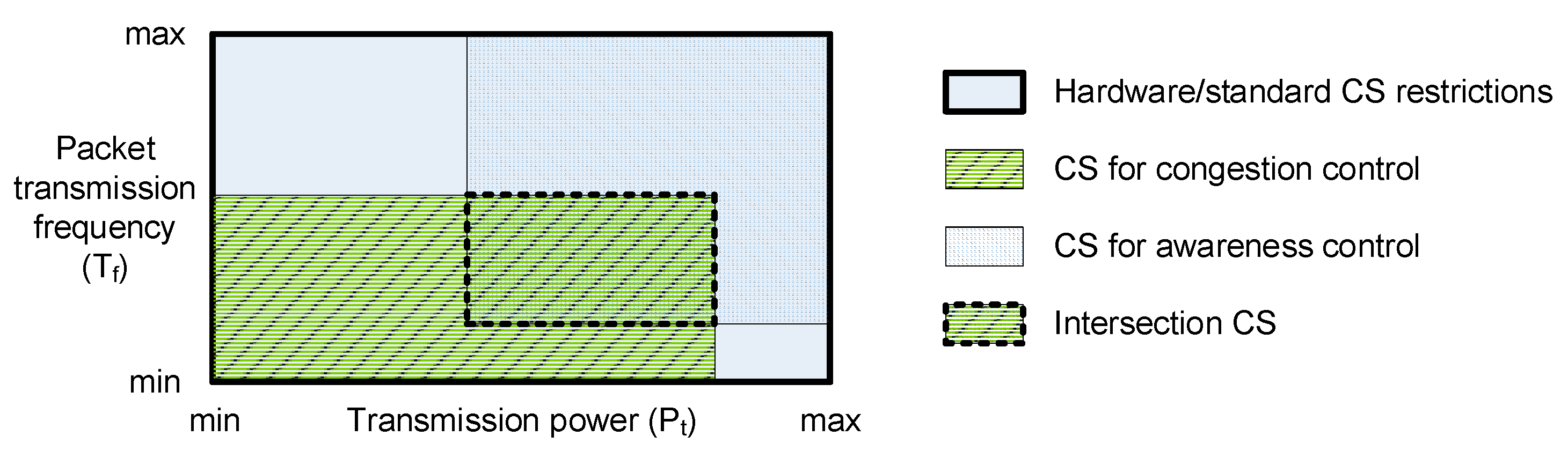
  • Each protocol operates independently, calculates its own CS, and reports it to COMPASS.
  • COMPASS calculates the Intersection CS based on the received CSs for each protocol.
  • COMPASS configures the communication parameters to be compliant with the identified ICS. Different criteria could then be applied to select the communication parameters within the identified ICS.
COMPASS dynamically adapts its operation to the conditions of the protocols it coordinates. If the CS for any of these protocols changes (e.g., because the channel load changes or the application requirements are modified), COMPASS calculates the new ICS and adapts the communication parameters based on the new ICS. The proposed COMPASS methodology constitutes a generic framework, and is independent of the protocols to be coordinated, their specific implementations, the method used to compute the CSs, the considered communication parameters, and the configuration of the communication parameters following the identified ICS.
The operation of COMPASS is here illustrated considering the coordination of A-DCC and MINT. COMPASS is independent of the mechanism used to configure the communication parameters. However, to evaluate its performance, it is necessary to specify how the communication parameters are configured once the ICS has been identified. Different options are possible, but in this study, the parameters are initially configured to the minimum values pertaining to the ICS (minimum Pt and Tf). The parameters are then dynamically adapted following an AIMD process (Additive Increase and Multiplicative Decrease). All vehicles piggyback the difference between their current Pt and Tf and the minimum Pt and Tf of their ICS, as well as the minimum values received from all neighboring nodes. This process modifies the DCC_NET piggybacking scheme since instead of exchanging channel load information, vehicles exchange information about the configuration of their communication parameters with respect to the minimum required. The information exchanged is used in the AIMD process to dynamically modify the configuration of the communication parameters within the ICS. Pt and Tf are increased if their increment is compliant with the computed ICS, or decreased otherwise. We consider additive factors of 0.25 dB and 0.05 Hz for increments, and a multiplicative factor of 0.025 for decrements. Additive factors are multiplied by 4 for vehicles for which the difference between Pt and Tf and the minimum Pt and Tf of the ICS is lower than the average values of vehicles within 2 hops. Similarly, the multiplicative factor is doubled for vehicles for which the difference between Pt and Tf and the minimum Pt and Tf of the ICS is higher than the average values of vehicles within 2 hops. The following algorithms formally describe using pseudo-code how COMPASS derives the ICS for a given vehicle (Algorithm 1) and updates its communication parameters (Algorithm 2). Both algorithms consider N neighboring vehicles, P protocols to be coordinated, and C communication parameters over which the protocols can act. In Algorithm 2, Δ k   a v g   represents the average difference between the communication parameters used by vehicles within 2 hops and the minimum parameters of their ICS. ak and mk represent the additive and multiplicative factors of communication parameter k (1 ≤ kC), respectively.
Algorithm 1. Derive own ICS
Input :   c k j m i n and   c k j   m a x for each protocol j and parameter k
Output :   c k m i n and   c k   m a x of the ICS for the vehicle executing COMPASS for each parameter k
1.   Initialization :   c k m i n =   0   and   c k   m a x = ∞ for 1 ≤ kC
2. For each protocol coordinated j (1 ≤ jP) do
3.    For each communication parameter k (1 ≤ kC) do
4.     if c k m i n is   lower   than   the   c k j m i n for protocol j do
5.       c k m i n = c k j m i n   reported for protocol j
6.     End If
7.     if c k   m a x is   higher   than   the   c k j   m a x   for protocol j do
8.      c k   m a x = c k j   m a x for protocol j
9.     End If
10.    End For
11. End For
Algorithm 2. Update communication parameters of the ego vehicle executing COMPASS
Input :   c k m i n and   c k   m a x of   the   ICS   of   the   ego   vehicle ,   c k and   c k m i n   for each neighbor
Output :   c k for each communication parameter k
1.   Initialization :   Δ k   a v g = 0 for 1 ≤ kC and Inc_flag = true
2. For each communication parameter k (1 ≤ kC) do
3.    For each 1-hop neighbor i (1 ≤ iN) do
4.     Δ k   a v g = Δ k   a v g + ( c k c k m i n ) i
5.    End For
6.    Δ k   a v g = Δ k   a v g / N
7.    if c k > c k m a x   of ego vehicle executing COMPASS
8.     Inc_flag = false
9.    End if
10. End for
11. For each communication parameter k (1 ≤ kC) do
12.    If Inc_flag is true do
13.     If c k c k m i n of   ego   vehicle   <   Δ k   a v g and   c k + 4 a k of   ego   vehicle   <   c k   m a x do
14.      c k = c k + 4 a k   for ego vehicle
15.     Else if c k + 2 a k of   ego   vehicle   <   c k   m a x do
16.      c k = c k + 2 a k   for ego vehicle
17.    End If
18.    Else
19.     if c k c k m i n of   ego   vehicle   >   Δ k   a v g and   c k ( 1 2 m k ) of   ego   vehicle   >   c k   m i n do
20.      c k = c k ( 1 2 m k )   for ego vehicle
21.     Else if c k ( 1 m k ) of   ego   vehicle   >   c k   m i n do
22.      c k = c k ( 1 m k )     for ego vehicle
23.     End If
24. End For

4. Evaluation

4.1. Scenario and Simulation Settings

The proposed COMPASS methodology is evaluated in a highway crossing scenario with 4 road segments and 4 lanes per road segment where vehicles are uniformly distributed in each lane. In the crossing scenario, we evaluate the spatial distribution of the channel load and the application’s effectiveness experienced by each vehicle. This scenario can be characterized by the traffic density in vehicles/km/lane, and the length of each of the four road segments (3.5 km). Three different traffic densities have been simulated (50, 75 and 100 vehicles/km/lane). The road topology can influence the performance and operation of the protocols considered in this study. The reliability, stability and effectiveness of congestion, awareness and topology control protocols have often been evaluated in straight highway scenarios where the spatial distribution of vehicles can be considered uniform, especially under free-flow conditions. With such a uniform distribution, all vehicles sense similar channel load levels, and the protocols can more easily converge to a stable solution. However, when vehicles sense different channel load levels, it is more difficult to guarantee the stability and fairness of protocols. In this context, the selected scenario is more challenging than for example a straight highway or T-way scenario. This is the case because highway crossing scenarios generally experience higher concentration levels of vehicles per square kilometer closer to the crossing area. As a result, vehicles close to the crossing area experience significantly higher channel load levels than vehicles located far away from the crossing area since they can sense more vehicles.
In the selected scenario, we consider that all vehicles periodically transmit 1-hop broadcast packets on the control channel using IEEE 802.11 p. Each packet has a payload of 250 Bytes, and contains the positioning, speed and basic status information of the transmitting vehicle. All vehicles initially use the same transmission power (by default Pt = 23 dBm) and a random packet transmission frequency (Tf) between 1 Hz and 10 Hz. Following [25], this study utilizes the Nakagami-m propagation model with m = 3. The radio interface is configured for all vehicles with a carrier sense threshold of −90 dBm and a reception threshold −82 dBm.
Awareness control protocols set the communication parameters so that application requirements are satisfied. Each vehicle in the scenario runs a vehicular application that requires that at least R packets are correctly received per second by all vehicles within a given communication range CR. To decouple this study from any particular application, vehicles set their initial application requirements randomly, with the communication range varying between 50 and 200 m and the packet reception frequency between 1 Hz and 10 Hz. From the initial settings, the application requirements linearly vary during the simulation. CBRmax has been set equal to 0.6 following [22]. The CBR values computed in this study have been obtained from the aggregation of all packets sensed by each vehicle’s radio interface, i.e., with a received signal higher than −90 dBm.
COMPASS can adapt its operation to the dynamics of the protocols it coordinates. In fact, COMPASS computes the ICS and reconfigures the communication parameters as soon as the CS of any of the protocols changes. The application requirements and the number of neighbors normally change at a slower pace than the channel load. As result, COMPASS is executed in this study every time a new CBR value is obtained. Following [23], a new CBR value is obtained every 250 ms, which is considered sufficiently high for COMPASS to be able to satisfactorily adapt its operation to the dynamics of the vehicular environment.
Table 1 summarizes the communication and simulation parameters. Simulations have been executed to ensure the statistical accuracy of the presented results. In this study, we used a vehicular network simulator implemented over Matlab to accurately simulate the performance and efficiency of vehicular communications and networking protocols. The simulator implements different propagation models, radio access technologies, and communication and networking protocols. We have extensive validated our implementation under different configurations and scenario conditions.

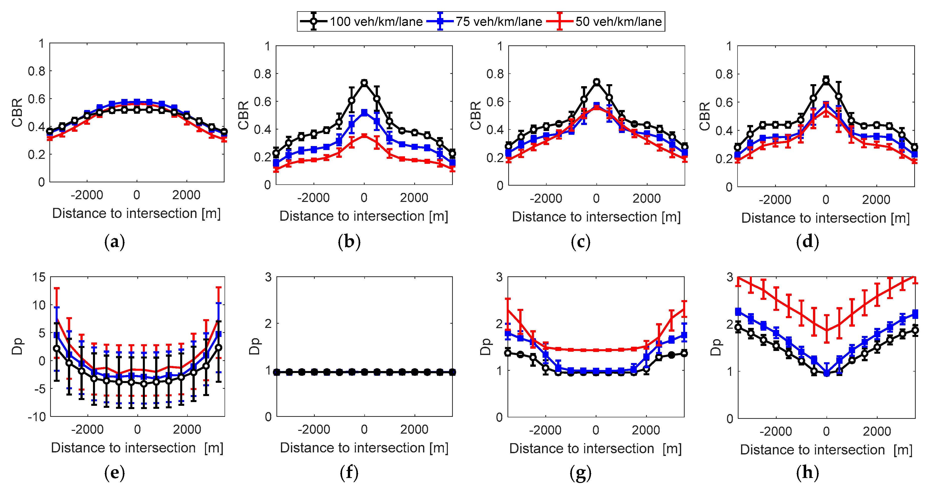
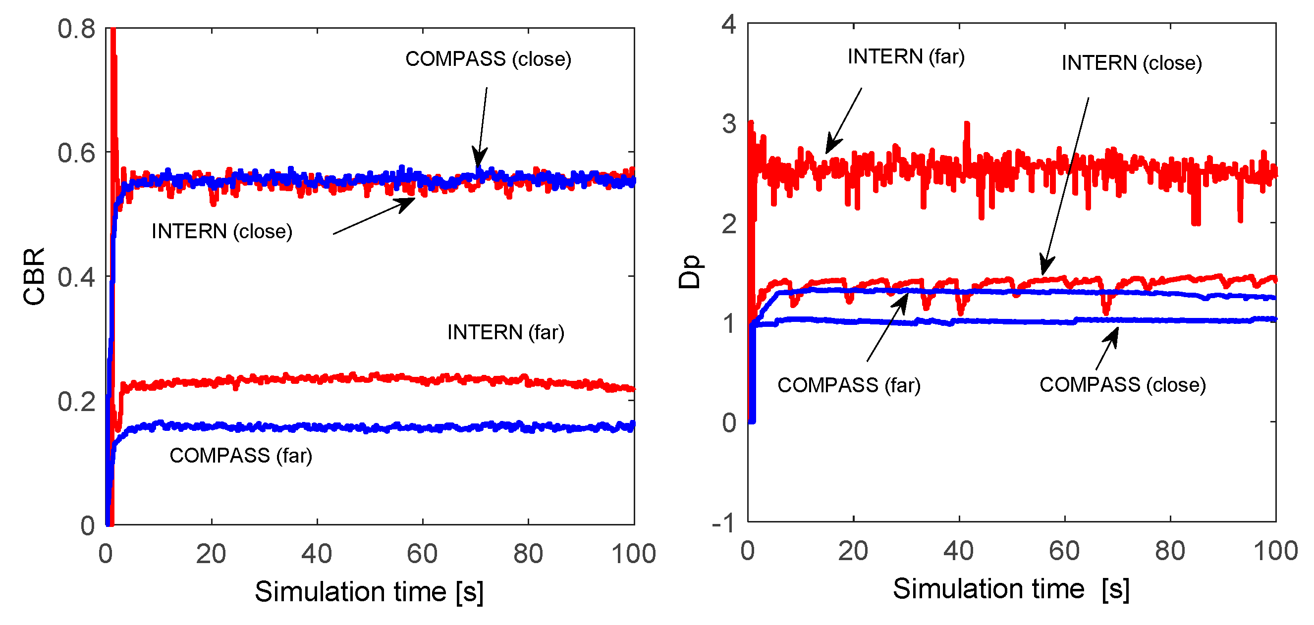
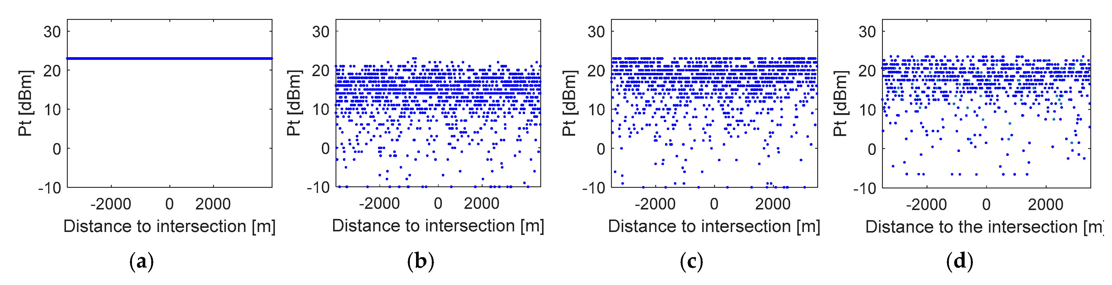
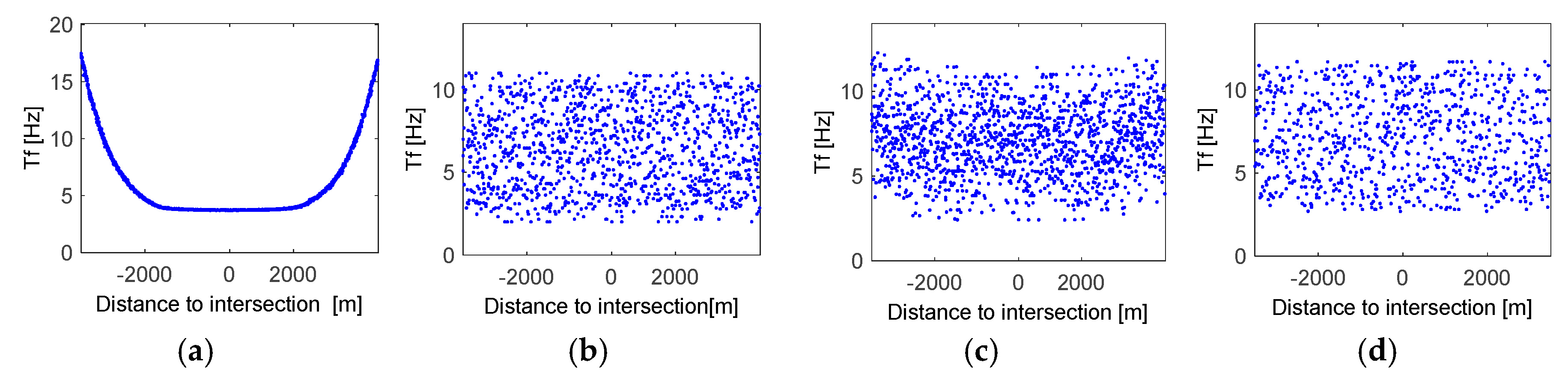
4.2. Congestion and Awareness Control

Figure 5 plots the average spatial distribution of the CBR and the Dp metric as a function of the distance to the intersection; the vertical lines represent the 5th and 95th percentiles. The Dp metric represents the difference between the number of packets demanded by the application (i.e., packet reception frequency) and the number of packets that are actually received per second at the communication range required by the application. An application is then satisfactorily supported if Dp > 0. The Dp values reported have been calculated taking into account packet losses due to propagation conditions. The results depicted in Figure 5a show that A-DCC successfully maintains the CBR below CBRmax = 0.6 irrespective of the traffic density. This trend was indeed expected since A-DCC has been designed to control the channel load. Congestion control protocols do not take into account that vehicles may have varying application requirements when setting the vehicles’ communication parameters. The results depicted in Figure 5e show that A-DCC does not always satisfy the applications requirements (Dp < 0). Only for low traffic densities, vehicles located at long distances to the intersection can achieve positive Dp values since they can use high packet frequencies compared to vehicles close to the intersection.
The results obtained show that the CBR experienced with MINT (Figure 5b) increases with the traffic density, especially at short distances to the intersection. This is the case because MINT configures each vehicle with the minimum packet transmission frequency and power required to satisfy its application requirements, and the protocol does not control the channel load. This results in that the application requirements are satisfied with a constant Dp metric independently of the traffic density (see Figure 5f). Under low and medium traffic densities, the use of the minimum required transmission settings results in that the channel is not fully utilized since the maximum experienced CBR is below CBRmax. These results demonstrate that, even if A-DCC does not always satisfy the application requirements, there is sufficient channel capacity available in the simulated scenario to satisfy the application requirements while maintaining the CBR below CBRmax. The experienced CBR with MINT only surpasses CBRmax under the highest simulated traffic density and for vehicles close to the intersection. In this case, the traffic density is so high that there is not sufficient channel capacity to satisfy the requirements of all vehicles without exceeding CBRmax at short distances to the intersection.
The results depicted in Figure 5c,g show that INTERN is able to satisfy the application requirements of all vehicles (Dp > 0) while maintaining the CBR below CBRmax, except for the highest traffic density scenario. In this scenario, the requirements of all vehicles cannot be satisfied without exceeding CBRmax, as it was also observed for MINT in Figure 5b. The direct comparison of INTERN and MINT shows that INTERN increases the use of the available bandwidth and augments the experienced Dp compared to MINT. Higher Dp levels reduce the risks of random channel variations that could provoke that transmission settings are not capable of guaranteeing the application requirements at the receiving vehicles.
The results obtained when applying the COMPASS methodology to coordinate A-DCC and MINT are depicted in Figure 5d,h. Figure 5d show that COMPASS is able to maintain the channel load levels below CBRmax = 0.6 (except for very high traffic densities as it was the case with MINT and INTERN), while satisfying the application requirements of all vehicles (Dp > 0 in Figure 5h). COMPASS is able to improve the Dp values with respect to INTERN, especially at short distances to the intersection and high traffic densities. Moreover, COMPASS offers better evolution perspectives since it does not require designing a new integrated scheme. This allowed, for example, the straightforward application of COMPASS to coordinate A-DCC and MINT, but also to coordinate other protocols such as PULSAR [23] and MINT. The analysis conducted with PULSAR and MINT yielded similar results as to those here presented when coordinating A-DCC and MINT: the CBR is maintained below CBRmax while the application requirements are satisfied for all vehicles Dp > 0. This demonstrates that the proposed COMPASS coordination methodology is independent of the specific protocol implementations, and can be applied to different congestion and awareness control schemes.
The convergence and stability of the control processes that are part of A-DCC and MINT is relevant for their correct operation. It is therefore important to analyze whether these properties are maintained when coordinating the operation of the two protocols using COMPASS. Figure 6 depicts for INTERN and COMPASS, the time evolution of the CBR and Dp metric for two selected vehicles and a traffic density of 75 veh/km/lane. One of these vehicles is located at the intersection (referred to as ‘close’ in the figure), where the maximum channel load is experienced. The other vehicle is located at around 2400 m from the intersection (referred to as ‘far’ in the figure). These two vehicles are selected to check the convergence and stability of the protocols under different conditions. Figure 6 shows that both protocols satisfy the application requirements during the simulation time as the Dp is maintained higher than 0. The channel load is also maintained below the required threshold during the simulation run. The results in Figure 6 show that COMPASS can maintain the convergence and stability properties of the protocols it coordinates. After an initial transition period of less than 5 s, the CBR and Dp metrics converge and their oscillations are kept below ±5% of their respective average values. The initial transition period is produced because all vehicles in the scenario initiate their operation at the same time (i.e., at simulation time equal to t = 0), which is unlikely to happen in a practical situation.
Figure 7 and Figure 8 represent a snapshot of the packet transmission frequency and power used by each vehicle in the scenario (each dot in the figure corresponds to a particular vehicle) after 50 s of simulation time. MINT, INTERN and COMPASS adapt the vehicles’ packet transmission frequency and power taking into account their individual application requirements. This results in that vehicles implementing these protocols can utilize different packet transmission frequency and power depending on their specific application requirements. The variability shown in Figure 7 and Figure 8 for the packet transmission frequency and power utilized when implementing INTERN, MINT or COMPASS is due to the fact that the application requirements for each vehicle have been randomly selected so that the study is not restricted to a particular application. In this case, INTERN, MINT and COMPASS adapt the configuration of the communication parameters to the application requirements, which explains the variability observed. However, it is important remembering (Figure 6) that the CBR and Dp metrics converge when implementing COMPASS and INTERN. A very different behavior is observed for A-DCC. First of all, A-DCC does not adapt the transmission power and all vehicles use the same power level (Figure 7a). A-DCC adapts the packet transmission frequency based on the channel load and not on the application requirements; in particular, the packet transmission frequency is adapted so that similar values are utilized by neighboring vehicles. This explains why we do not observe a scattered plot in Figure 8a even though the application requirements were also randomly selected with A-DCC.

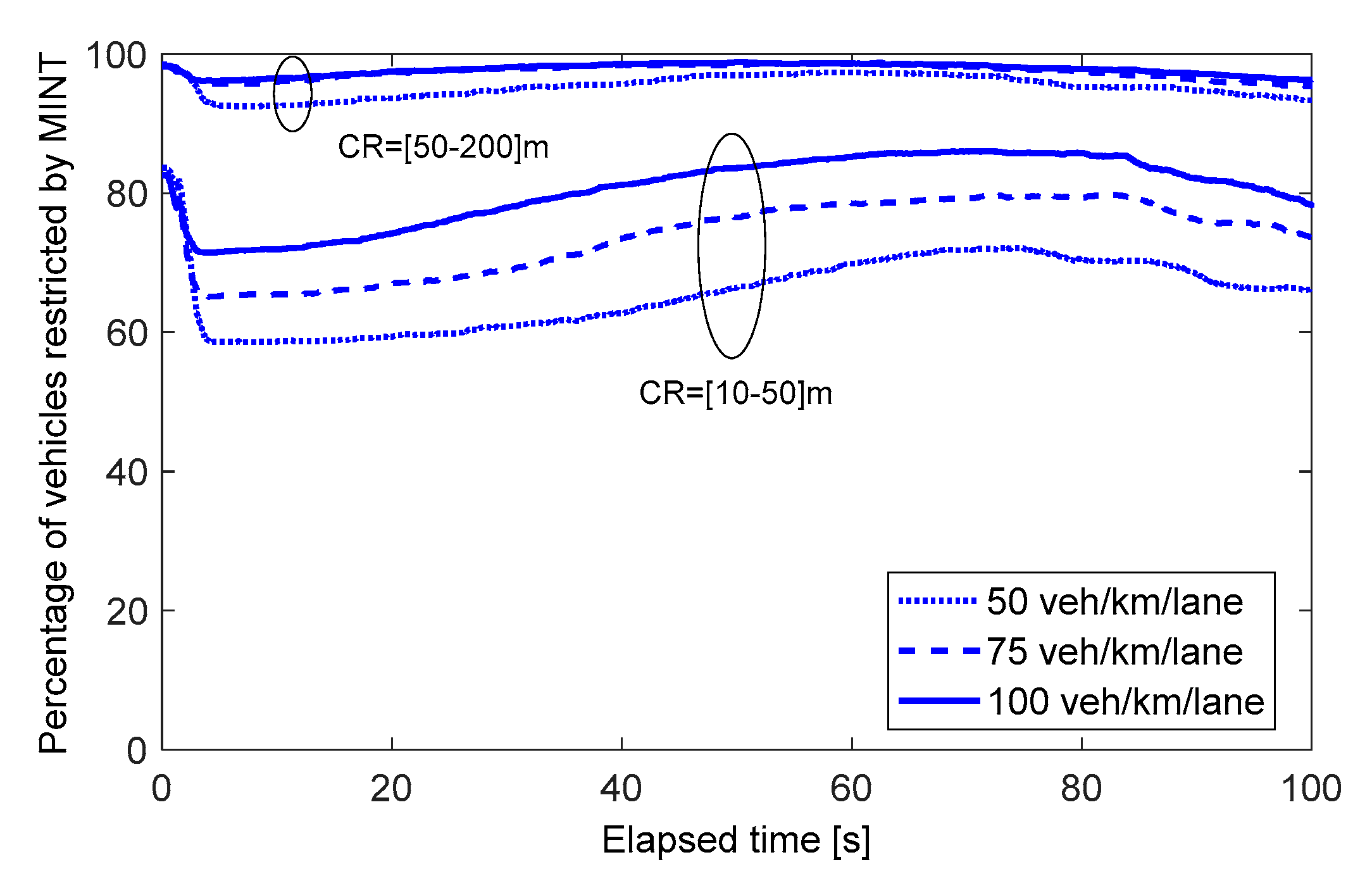
4.3. Congestion, Awareness and Topology Control

The proposed COMPASS coordination methodology offers better evolution perspectives than integrated solutions, and could be directly used within ETSI’s DCC framework to coordinate congestion and awareness control functions. Another important advantage of COMPASS is that it can coordinate multiple protocols operating over the same parameters. To demonstrate this, we have also evaluated the capacity of COMPASS to coordinate congestion, awareness and topology control protocols. While the integration of the three protocols is not straightforward, their coordination using COMPASS is simple. It only requires computing the protocols’ CSs and the Intersection CS (the process previously explained is maintained). The topology control protocol here implemented for illustrative purposes is an ideal scheme designed to maintain the number of neighbors above a minimum threshold in order to ensure certain network connectivity. To this aim, the topology control protocol linearly increases the minimum transmission power required until 25 vehicles are present in the neighbor table. Similarly, the transmission power is linearly decreased when more than 250 vehicles are present in the neighbor table. The transmission power is increased or decreased in 1 dB steps. The topology control protocol is hence referred to as TOWER (Topology Control through Linear Power Control). COMPASS has been applied to coordinate the congestion (A-DCC), awareness (MINT) and topology (TOWER) control protocols. Figure 9 plots the spatial distribution of the average CBR, Dp and number of neighbors. The results are shown for different ranges of the CR requirement. The results depicted in Figure 9 show that COMPASS is capable to successfully coordinate the operation of the congestion, awareness and topology control protocols since the CBR is maintained below CBRmax, Dp is higher than 0 for all vehicles, and the number of neighbor vehicles is maintained above the 25 minimum threshold. These results clearly demonstrate that COMPASS is capable to successfully coordinate different protocols that operate on the same communication parameters without modifying their implementation or having to design new integrated solutions.
This section also analyzes the capacity of COMPASS to adapt its coordination process to varying context and operating conditions. The coordination of A-DCC, MINT and TOWER results in that the minimum transmission power that each vehicle requires is established by the topology or awareness control protocols (depending on the context conditions) since A-DCC is designed to utilize a fixed transmission power. In the case of the higher range of CR values (50 to 200 m), the transmission power level required by the awareness control protocol is high, and therefore the number of neighboring vehicles is also high. As a result, the minimum transmission power to be used (compliant with the ICS) is established by the awareness control process, and not by the topology control protocol. On the other hand, when we consider the lower CR range (10–50 m), the transmission power required for awareness control is lower, and the minimum required transmission power (again compliant with the ICS) is in many cases the one demanded by the topology control process. These trends are illustrated in Figure 10. This figure depicts the time evolution of the percentage of vehicles with a required minimum transmission power (i.e., minimum transmission power in the ICS) established by the awareness control protocol MINT. The minimum transmission power is established by the topology control TOWER for the rest of vehicles since A-DCC is designed to utilize a fixed transmission power. Figure 10 shows that when the communications range requirements increase, the minimum transmission power is limited by the awareness control process MINT. However, when the communications range requirements are relaxed to 10–50 m, the percentage of vehicles with a required minimum transmission power established by the awareness control process is reduced; this is the case because the transmission power level needed by the topology control process increases. Figure 10 also shows that higher traffic densities increase the number of neighboring vehicles, and therefore the percentage of vehicles with a required minimum transmission power established by the awareness control process, and not by the topology control process as it requires lower transmission power levels. These results demonstrate that COMPASS is capable to adapt its coordination process to the context conditions, even when considering multiple interacting protocols and diverse operating conditions.

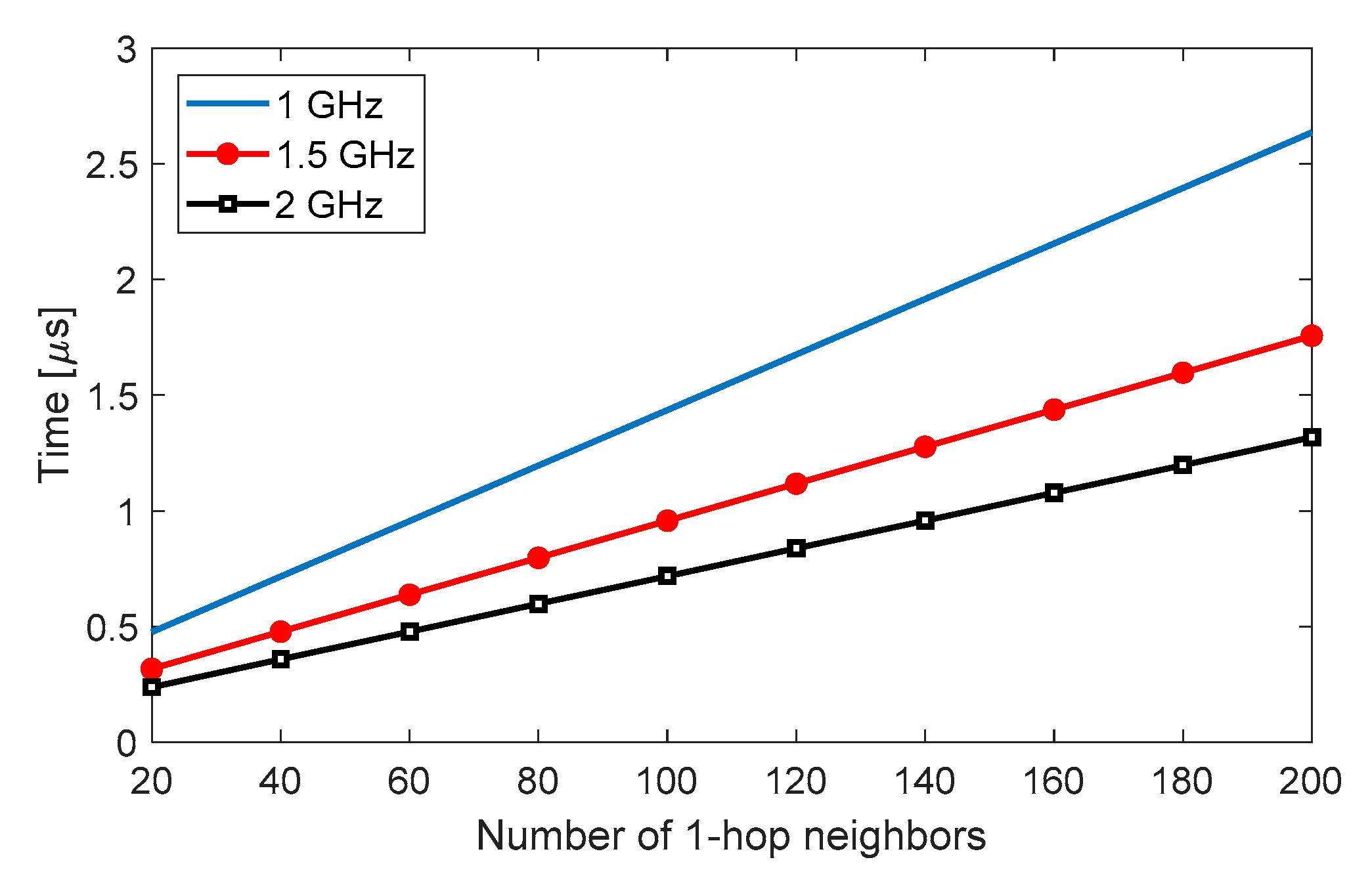
4.4. Computational Cost

Table 2 and Table 3 show an upper bound of the number of CPU cycles needed by COMPASS to execute each line of Algorithms 1 and 2. These algorithms are executed by COMPASS to derive the ICS and adapt the communication parameters, respectively. The Repetitions column represents how many times each algorithm line needs to be executed (many are inside for loops). It is an upper bound because some lines are only executed when a certain condition is satisfied (If-Else sentences). The number of CPU cycles has been computed considering Intel CPU architectures [30]. For example, the addition or subtraction require 1 CPU cycle, the multiplication of two floating point numbers requires 5 CPU cycles, and their division requires 39 cycles. Using these tables, we can estimate an upper bound of the total number of CPU cycles needed to run COMPASS. Figure 11 plots the upper bound of the CPU time needed to run COMPASS for different CPU speeds and a varying number of neighboring vehicles. The results shown consider C = 3 communication parameters and P = 3 interacting protocols for varying number of neighboring vehicles, N. The parameters considered represent realistic scenarios. For these scenarios, Figure 11 shows that the time needed to execute COMPASS is below 3 µs. These results provide clear evidences that COMPASS has a low computational cost, and it is hence feasible to implement it in real systems without introducing significant delays.

5. Discussion

The integrated and coordinated approaches have been analyzed under scenarios where the protocols’ CSs were not disjoint. It can be possible that certain operating conditions produce an empty ICS (i.e., a set with no elements). In this case, it is not possible to find a configuration of the communication parameters that simultaneously satisfies the requirements of all protocols. Considering awareness and congestion control, this situation could occur when the channel load and application’s requirements are so high that the maximum communication parameters allowed by the congestion control process are lower than the minimum ones demanded by the awareness control process. In other words, this situation can occur when the channel capacity is not sufficient to simultaneously satisfy the application’s requirements of all vehicles. It can be considered a general problem of vehicular wireless networks that has not been fully solved yet. In fact, this is not a specific problem of COMPASS, since it is also produced with other protocols dealing with awareness control (e.g., INTERN and MINT in this study).
Mechanisms exist to increase the channel capacity and try avoiding the described situation. Vehicles could use higher-order modulation and coding schemes to increase the data rate and therefore the channel capacity [31]. In addition, the information to be transmitted could be compressed by the higher layers of the protocol stack to reduce the packet size before each transmission [32]. Another interesting approach would be the combination of networking coding and multi-hop beaconing. Network coding can exploit the characteristics of the broadcast communication channel to increase the network’s capacity or throughput [33]. When using network coding, a forwarding node combines multiple packets into a single coded one. An adequate selection of nodes to forward broadcast messages using network coding could enable the reduction of the transmission power levels needed by awareness control, and thereby decrease the overall channel load. Certain studies claim that multi-hop beaconing can be inefficient compared to single-hop beaconing schemes employing higher transmission power levels [34], although recent studies have shown its potential to improve the communications range if the relays are properly selected [35,36]. The combined use of multi-hop beaconing with network coding could offer room to improve the channel capacity [37,38]. Reducing the number of messages transmitted on the channel could also be an alternative approach to reduce the probability of an empty ICS due to insufficient channel capacity. In this case, the packet transmission frequency could be decreased, or lower priority messages (taking into account the vehicles’ context) could be discarded, postponed or transmitted on different channels [39].
Despite these alternatives, it might still happen that an empty ICS cannot be avoided, even with the integrated approach since it can be considered a general problem of vehicular wireless networks. In this case, achieving a configuration of parameters that satisfies all protocols will not be possible, and it will be necessary to define certain priority levels among protocols. In the scenario discussed in this paper, this is equivalent to decide whether it is more relevant to guarantee a load below CBRmax, provide the awareness levels required by the application’s requirements, or maintain a certain number of neighbor vehicles. It is important noting that certain vehicles might have more strict awareness or topology control requirements based on their road traffic context. As a result, priority decisions can be taken at the vehicle’s level and be context-dependent. In any case, the design of solutions to increase channel capacity or tackle situations where the channel capacity is insufficient are out of the scope of this paper that is focused on the proposal of a methodology for the cross-layer coordination of protocols in vehicular networks.

6. Conclusions

This paper has presented and evaluated COMPASS, a novel methodology for the cross-layer coordination of protocols in vehicular networks that act or depend on the same communication parameters. The proposal has been designed to solve possible negative interactions or conflicts that may arise between such protocols when operating independently of each other. The proposed coordination methodology provides significant benefits over alternative methodologies such as integrating the conflicting or interacting protocols. In particular, the coordination methodology is independent of the protocols to be coordinated, their specific implementations, and the communication parameters over which these protocols actuate. In addition, the coordination methodology does not require changing the original protocols, which facilities the evolution of vehicular networks and standards, and the coexistence with legacy solutions. The proposal has a low computational complexity which facilitates its real-world implementation and possible impact on standardization. COMPASS can be implemented as part of the Management layers specified for ITS communications architectures in ETSI or ISO. The proposed methodology has been initially designed to demonstrate the feasibility to effectively coordinate congestion and awareness control protocols. However, this study has also demonstrated the capacity of the proposed methodology to coordinate additional protocols that operate over the same parameters. Such capacity has been demonstrated considering the coordination of vehicular congestion, awareness and topology control protocols under diverse context conditions.
The conclusions of this study identify possible future research directions. For example, COMPASS could be further fine-tuned and optimized under more dynamic scenarios and real road topologies. COMPASS could also be designed so its operation is adapted based on the context conditions of each vehicle. Such adaptation could be designed to approximate the optimal solution so that all application requirements are satisfied and the maximum channel capacity is not reached. Other alternative approaches to select the communication parameters within the ICS could also be investigated. COMPASS could also be proposed for congestion control in C-V2X or LTE-V. In fact, C-V2X Mode 4 as specified under 3GPP Release 14 identifies the need for congestion control but does not specify a particular congestion control protocol. ETSI and 3GPP are currently analyzing whether the current DCC solution could be valid for C-V2X Mode 4. This study has also shown than under certain conditions the IEEE 802.11p channel capacity might not be sufficient to simultaneously satisfy the application requirements of all vehicles. Novel mechanisms to increase the channel capacity could be considered and be further investigated, including the use of higher-order modulation and coding schemes, compression techniques, the combination of network coding and multi-hop beaconing, or the joint optimization of data rate, transmission power and packet transmission frequency, among others. In addition, the definition of priority levels among protocols or vehicles could be investigated to tackle situations where the channel capacity is insufficient.

Author Contributions

Conceptualization, J.G.; methodology, J.G. and M.S.; software, M.S.; validation, M.S.; formal analysis, M.S.; investigation, J.G. and M.S.; writing-original draft preparation, M.S.; writing-review and editing, J.G.; supervision, J.G.; project administration, J.G.; funding acquisition, J.G.
Funding: This work was supported in part by the Spanish Ministry of Economy and Competitiveness and FEDER funds under the projects TEC2014-57146-R and TEC2017-88612-R.

Conflicts of Interest

The authors declare no conflict of interest.

References

  1. Naik, G.; Liu, J.; Park, J.J. Coexistence of Wireless Technologies in the 5 GHz Bands: A Survey of Existing Solutions and a Roadmap for Future Research. IEEE Commun. Surv. Tutor. 2018, 20, 1777–1798. [Google Scholar] [CrossRef]
  2. Basheer, H.S.; Bassil, C. A review of broadcasting safety data in V2V: Weaknesses and requirements. Ad Hoc Netw. 2017, 65, 13–25. [Google Scholar] [CrossRef]
  3. Jabbarpour, M.R.; Noor, R.M.; Khokhar, R.H.; Ke, C.-H. Cross-layer congestion control model for urban vehicular environments. J. Netw. Comput. Appl. 2014, 44, 1–16. [Google Scholar] [CrossRef]
  4. Intelligent Transport Systems (ITS). Communications Architecture; ETSI EN 302 665 V1.1.1. Available online: https://www.etsi.org/deliver/etsi_en/302600_302699/302665/01.01.01_60/en_302665v010101p.pdf (accessed on 25 October 2018).
  5. Intelligent Transport Systems (ITS). Cross Layer DCC Management Entity for Operation in the ITS G5A and ITS G5B Medium; ETSI TS 103 175 V1.1.1. Available online: https://www.etsi.org/deliver/etsi_ts/103100_103199/103175/01.01.01_60/ts_103175v010101p.pdf (accessed on 25 October 2018).
  6. Intelligent Transport Systems (ITS). Decentralized Congestion Control Mechanisms for Intelligent Transport Systems Operating in the 5 GHz Range; Access Layer Part; ETSI TS 102 687 V1.1.1. Available online: https://www.etsi.org/deliver/etsi_ts/102600_102699/102687/01.01.01_60/ts_102687v010101p.pdf (accessed on 25 October 2018).
  7. Intelligent Transport Systems (ITS). GeoNetworking; Part 4: Geographical Addressing and Forwarding for Point-to-Point and Point-to-Multipoint Communications; Sub-Part 2: Media-Dependent Functionalities for ITS-G5; ETSI TS 102 636-4-2 V1.1.1. Available online: https://www.etsi.org/deliver/etsi_ts/102600_102699/1026360402/01.01.01_60/ts_1026360402v010101p.pdf (accessed on 25 October 2018).
  8. Intelligent Transport Systems (ITS). Facilities Layer; Communication Congestion Control; ETSI TS 103 141 V0.0.9. Available online: https://portal.etsi.org/webapp/workProgram/Report_WorkItem.asp?wki_id=37124 (accessed on 25 October 2018).
  9. Sepulcre, M.; Mittag, J.; Santi, P.; Hartenstein, H.; Gozalvez, J. Congestion and Awareness Control in Cooperative Vehicular Systems. Proc. IEEE 2011, 99, 1260–1279. [Google Scholar] [CrossRef] [Green Version]
  10. Gozalvez, J.; Sepulcre, M. Opportunistic technique for efficient wireless vehicular communications. IEEE Veh. Technol. Mag. 2007, 2, 33–39. [Google Scholar] [CrossRef]
  11. Sepulcre, M.; Gozalvez, J.; Harri, J.; Hartenstein, H. Application-Based Congestion Control Policy for the Communication Channel in VANETs. IEEE Commun. Lett. 2010, 14, 951–953. [Google Scholar] [CrossRef]
  12. Giang, A.T.; Lambert, A.; Busson, A.; Gruyer, D. Topology control in VANET and capacity estimation. In Proceedings of the IEEE Vehicular Networking Conference (VNC), Boston, MA, USA, 16–18 December 2013; pp. 135–142. [Google Scholar]
  13. Srivastava, V.; Motani, M. Cross-layer design: A survey and the road ahead. IEEE Commun. Mag. 2005, 43, 112–119. [Google Scholar] [CrossRef]
  14. Fu, B.; Xiao, Y.; Deng, H.J.; Zeng, H. A Survey of Cross-Layer Designs in Wireless Networks. IEEE Commun. Surv. Tutor. 2014, 16, 110–126. [Google Scholar] [CrossRef]
  15. Edirisinghe, R.; Zaslavsky, A. Cross-Layer Contextual Interactions in Wireless Networks. IEEE Commun. Surv. Tutor. 2014, 16, 1114–1134. [Google Scholar] [CrossRef]
  16. Babber, K.; Randhawa, R. Cross-Layer Designs in Wireless Sensor Networks. In Computational Intelligence in Sensor Networks; Mishra, B., Dehuri, S., Panigrahi, B., Nayak, A., Das, H., Eds.; Studies in Computational Intelligence; Springer: Berlin/Heidelberg, Germany, 2012; Volume 776. [Google Scholar]
  17. Williams, B. The CALM Handbook; ISO TC204, v1.2; George Ronald Publisher: Herts, UK, September 2004. [Google Scholar]
  18. Molina-Masegosa, R.; Gozalvez, J. LTE-V for Sidelink 5G V2X Vehicular Communications: A New 5G Technology for Short-Range Vehicle-to-Everything Communications. IEEE Veh. Technol. Mag. 2017, 12, 30–39. [Google Scholar] [CrossRef]
  19. Intelligent Transport Systems (ITS). Cross Layer DCC Management Entity for Operation in the ITS G5A and ITS G5B Medium; Validation Set-Up and Results; ETSI TR 101 613 V1.1.1. Available online: https://www.etsi.org/deliver/etsi_tr/101600_101699/101613/01.01.01_60/tr_101613v010101p.pdf (accessed on 25 October 2018).
  20. Rostami, A.; Cheng, B.; Bansal, G.; Sjöberg, K.; Gruteser, M.; Kenney, J.B. Stability Challenges and Enhancements for Vehicular Channel Congestion Control Approaches. IEEE Trans. Intell. Transp. Syst. 2016, 17, 2935–2948. [Google Scholar] [CrossRef]
  21. Bansal, G.; Kenney, J.B.; Rohrs, C.E. LIMERIC: A Linear Adaptive Message Rate Algorithm for DSRC Congestion Control. IEEE Trans. Veh. Technol. 2013, 62, 4182–4197. [Google Scholar] [CrossRef]
  22. Bansal, G.; Kenney, J.B. Controlling Congestion in Safety-Message Transmissions: A Philosophy for Vehicular DSRC Systems. IEEE Veh. Technol. Mag. 2013, 8, 20–26. [Google Scholar] [CrossRef]
  23. Tielert, T.; Jiang, D.; Chen, Q.; Delgrossi, L.; Hartenstein, H. Design Methodology and Evaluation of Rate Adaptation Based Congestion Control for Vehicle Safety Communications. In Proceedings of the IEEE Vehicular Networking Conference (VNC), Amsterdam, The Netherlands, 14–16 November 2011. [Google Scholar]
  24. An, N.; Maile, M.; Jiang, D.; Mittag, J.; Hartenstein, H. Balancing the Requirements for a Zero False Positive/Negative Forward Collision Warning. In Proceedings of the Annual Conference on Wireless On-Demand Network Systems and Services (WONS), Banff, AB, Canada, 18–20 March 2013; pp. 191–195. [Google Scholar]
  25. Tielert, T.; Jiang, D.; Hartenstein, H.; Delgrossi, L. Joint power/rate congestion control optimizing packet reception in vehicle safety communications. In Proceedings of the ACM International Workshop on VehiculAr InterNETworking (VANET), Taipei, Taiwan, 25 June 2013; pp. 51–60. [Google Scholar]
  26. Killat, M.; Hartenstein, H. An empirical model for probability of packet reception in vehicular ad hoc networks. EURASIP J. Wirel. Commun. Netw. 2009. [Google Scholar] [CrossRef]
  27. Sepulcre, M.; Gozalvez, J.; Altintas, O.; Kremo, H. Integration of congestion and awareness control in vehicular networks. Ad Hoc Netw. 2016, 37 Pt 1, 29–43. [Google Scholar] [CrossRef]
  28. Zhang, L.; Valaee, S. Congestion Control for Vehicular Networks with Safety-Awareness. IEEE/ACM Trans. Netw. 2016, 24, 3290–3299. [Google Scholar] [CrossRef]
  29. Frigau, M.S. Fair Decentralized Congestion and Awareness Control for Vehicular Networks. In Proceedings of the IEEE 21st International Conference on Parallel and Distributed Systems (ICPADS), Melbourne, Australia, 14–17 December 2015; pp. 172–180. [Google Scholar]
  30. Intel. Intel® 64 and IA-32 Architectures Optimization Reference Manual; Order Number: 248966-033; Intel: Santa Clara, CA, USA, June 2016. [Google Scholar]
  31. Sepulcre, M.; Gozalvez, J.; Coll-Perales, B. Why 6Mbps is not (always) the Optimum Data Rate for Beaconing in Vehicular Networks. IEEE Trans. Mob. Comput. 2017, 16, 3568–3579. [Google Scholar] [CrossRef]
  32. Sepulcre, M.; Tercero, P.; Gozalvez, J. Can Beacons be Compressed to Reduce the Channel Load in Vehicular Networks? In Proceedings of the IEEE Vehicular Networking Conference (VNC), Taipei, Taiwan, 5–7 December 2018. [Google Scholar]
  33. Ahlswede, R.; Cai, N.; Li, S.; Yeung, R. Network information flow. IEEE Trans. Inf. Theory 2000, 46, 1204–1216. [Google Scholar] [CrossRef] [Green Version]
  34. Mittag, J.; Thomas, F.; Harri, J.; Hartenstein, H. A comparison of single- and multi-hop beaconing in VANETs. In Proceedings of the ACM International Workshop on Vehicular InterNETworking (VANET), Beijing, China, 25 September 2009; pp. 69–78. [Google Scholar]
  35. Noor-A-Rahim, M.; Ali, G.G.M.N.; Nguyen, H.; Guan, Y.L. Performance Analysis of IEEE 802.11p Safety Message Broadcast with and Without Relaying at Road Intersection. IEEE Access 2018, 6, 23786–23799. [Google Scholar] [CrossRef]
  36. Nguyen, H.; Noor-A-Rahim, M.; Liu, Z.; Jamaludin, D.; Guan, Y.L. A Semi-Empirical Performance Study of Two-Hop DSRC Message Relaying at Road Intersections. Information 2018, 9, 147. [Google Scholar] [CrossRef]
  37. Sepulcre, M.; Gozalvez, J.; Gisbert, J.R. On the Potential of Network Coding for Cooperative Awareness in Vehicular Networks. In Proceedings of the IEEE International Workshop on Automotive IoT (IEEE Auto-IoT 2015), Milan, Italy, 14–16 December 2015. [Google Scholar]
  38. Ali, G.G.M.N.; Noor-A-Rahim, M.; Chong, P.H.J.; Guan, Y.L. Analysis and Improvement of Reliability Through Coding for Safety Message Broadcasting in Urban Vehicular Networks. IEEE Trans. Veh. Technol. 2018, 67, 6774–6787. [Google Scholar] [CrossRef]
  39. Kosch, T.; Adler, C.J.; Eichler, S.; Schroth, C.; Strassberger, M. The scalability problem of vehicular ad hoc networks and how to solve it. IEEE Wirel. Commun. 2006, 13, 22–28. [Google Scholar] [CrossRef] [Green Version]
Figure 1. Decentralized Congestion Control (DCC) in the ETSI ITS Communications architecture [6].
Electronics 07 00335 g001
Figure 2. Highway scenario with a traffic jam in one direction of driving and free flow conditions in the other direction. Vehicles under the same channel load conditions can have different application requirements.
Electronics 07 00335 g002
Figure 3. Integration and coordination of protocols operating over the same communication parameters. (a) Independent. (b) Integration. (c) Coordination.
Electronics 07 00335 g003
Figure 4. COMPASS configuration sets when coordinating congestion and awareness control protocols.
Electronics 07 00335 g004
Figure 5. Average spatial distribution of the CBR and Dp metric experienced with the different protocols analyzed. The vertical lines represent the 5th and 95th percentiles. The application requirements are satisfied if Dp > 0. (a) A-DCC. (b) MINT. (c) INTERN. (d) COMPASS. (e) A-DCC. (f) MINT. (g) INTERN. (h) COMPASS.
Electronics 07 00335 g005
Figure 6. Time evolution of the CBR and the Dp metric during a simulation run. The results are shown for two vehicles that implement INTERN (integrating A-DCC and MINT), and COMPASS (coordinating A-DCC and MINT), and a traffic density of 75 veh/km/lane.
Electronics 07 00335 g006
Figure 7. Snapshot of the packet transmission power used by each vehicle after 50 s of simulation time for a traffic density of 50 veh/km/lane. (a) A-DCC. (b) MINT. (c) INTERN. (d) COMPASS.
Electronics 07 00335 g007
Figure 8. Snapshot of the transmission frequency used by each vehicle after 50 s of simulation time for a traffic density of 50 veh/km/lane. (a) A-DCC. (b) MINT. (c) INTERN. (d) COMPASS.
Electronics 07 00335 g008
Figure 9. Average of the CBR, Dp metric and number of neighbor vehicles when applying COMPASS to coordinate the operation of A-DCC, MINT and TOWER. The results are shown for a traffic density of 75 veh/km/lane and two possible ranges of the communication range (CR) requirements: between 50–200 m and between 10–50 m.
Electronics 07 00335 g009
Figure 10. Time evolution of the percentage of vehicles with a required minimum transmission power established by the awareness control protocol MINT. The results are obtained with COMPASS coordinating the operation of A-DCC, MINT and TOWER. The results are depicted for different traffic densities and two possible intervals of the communication range (CR) requirements: between 50–200 m and between 10–50 m.
Electronics 07 00335 g010
Figure 11. Upper bound of the CPU time needed to execute COMPASS for 3 CPU speeds, C = 3 communication parameters and P = 3 interacting protocols.
Electronics 07 00335 g011
Table 1. Communications and simulation parameters.
ParameterValue
Packet size [Bytes]250
Min. and Max. transmission power [dBm]−10 and 23
Min. and Max. packet tx frequency [Hz]1 and 20
Min. and Max. ΔTf [Hz]1 and 3
Data rate [Mbps]6
Carrier sense threshold [dBm]−90
Reception threshold [dBm]−82
Target channel busy ratio (CBRmax)0.6
CBR measurement period [ms]250
Communication range required (CR) [m]50–200
Packet reception frequency required (R) [Hz]1–10
Traffic density [vehicles/km/lane]50, 75, 100
Simulation time [s] and simulation runs150 and 10
Table 2. Computational cost of Algorithm 1.
Algorithm LineCPU CyclesRepetitions
11C
211
31P
41P·C
51P·C
61P·C
81P·C
91P·C
Table 3. Computational cost of Algorithm 2.
Algorithm LineCPU CyclesRepetitions
11C + 1
21C
31C·N
43C·N
639C
81C
111C
121C
139C
147C

