Article

Modelling of the Power Interface of the Digital-Physical Hybrid Simulation System of a VSC-HVDC Based on Virtual Resistance Compensation

School of Electrical Engineering, Wuhan University, Wuhan 430000, China
*
Author to whom correspondence should be addressed.
Electronics 2018, 7(11), 333; https://doi.org/10.3390/electronics7110333
Submission received: 26 September 2018 / Revised: 13 November 2018 / Accepted: 13 November 2018 / Published: 19 November 2018
(This article belongs to the Section Power Electronics)

Abstract

:
To enhance the stability and accuracy of the digital-physical hybrid simulation system of a modular multilevel converter-based high voltage direct current (MMC-HVDC) system, this paper presents an improved power interface modeling algorithm based on ideal transformer method (ITM). By analyzing the stability condition of a hybrid simulation system based on the ITM model, the current of a so-called virtual resistance is added to the control signal of the controlled current source in the digital subsystem, and the stability of the hybrid simulation system with the improved power interface model is analyzed. The value of the virtual resistance is optimized by comprehensively considering system stability and simulation precision. A two-terminal bipolar MMC-HVDC simulation system based on the proposed power interface model is established. The comparisons of the simulation results verify that the proposed method can effectively improve the stability of the hybrid simulation system, and at the same time has the advantages of high simulation accuracy and easy implementation.

1. Introduction

The topology of a voltage source converter-high voltage direct current (VSC-HVDC) system is evolving gradually from the monopole to the pseudo bipolar, and then the newly true bipolar, to accommodate the ever-increasing capacity of the electric power to be transmitted [1,2,3]. The dynamic behavior of an MMC-based bipolar VSC-HVDC system, which is characterized by a large number of power electronic devices and more diversified operation modes, is so complicated that it is hard to predict accurately with a pure digital simulator [4], thus this urges the development of a digital-physical hybrid simulation (DPHS) system [5,6].
Playing a key role in integrating the digital simulation subsystem with the physical scaled subsystem to implement a DPHS, the power interface unit has attracted considerable attention regarding its control accuracy, response speed, and the most concerning issue, the modeling method.
Currently, the ideal transformer method (ITM) and damping impedance method (DIM) are the two effective methods to accurately represent the power interface burdened with the physical subsystem in the digital subsystem.
ITM, which was first proposed in Reference [7], is more appreciated since it can part the VSC-HVDC system into two subsystems at any desired location in a direct and convenient way. Reference [8] carries out theoretical analysis of the performance of the ITM from the aspects of system stability and simulation accuracy, and concludes that this method is of a better active load capacity but a poor system stability. Inserting a passive element, for example an inductor [9], into the physical subsystem seems to be an intuitive and easy way to improve the stability of an ITM-based DPHS system. However, this newcomer that originally does not belong to a VSC-HVDC system implies a higher power loss and implementation cost of the DYHS system, and more importantly, degrades the simulation accuracy. Additionally, aiming at improving the stability of a DYHS system, References [10,11] present a so-called feedback current filtering method that can be realized conveniently in software. However, the practicability of this method is very limited due to the difficulty in tuning the parameters of the filter. Based on the fact that the stability conditions for the voltage-source-ITM and current-source-ITM are exactly contrary to each other, reference [12] proposes a novel real-time switching ITM-based algorithm that when one type of ITM fails to guarantee the system stability, the other type of ITM is then activated in time, thereby maintaining the stable operation of a DPHS system in all the circumstances. However, the lack of a reliable and universal criterion for the switching of the ITM methods hinders the wide application of this method. In summary, the ITM has stability problems and needs appropriate improvement.
As for the DIM-based methods proposed in [13,14,15] that intend to achieve real-time impedance matching by solving the equivalent impedance of the physical subsystem based on the measurements of the voltage and current at the port of the power interface unit interfacing with the physical subsystem, they are expected to be improved further to accommodate for an active system of which the equivalent impedance varies sharply and frequently, such as the VSC-HVDC. In general, the DIM solves the stability problem, but its implementation is more complicated.
This paper proposes a novel concept of virtual resistance compensation for modelling the power interface unit of the DPHS of a VSC-HVDC system, aiming at improving the system stability in a cost-effective way. The major innovation of this paper is as follows: (1) the control signal of the controlled current source utilized in the current ITM to represent the power interface unit burdened with the physical subsystem is improved by adding the current of a virtual resistance. This tiny modification in the model of the power interface unit not only can improve the stability of the whole DPHS system dramatically, but also facilitate the implementation of the proposed method greatly. (2) By comprehensively considering the system ability improvement and simulation accuracy, the value of the virtual resistance is properly tuned, thus guaranteeing the desired performances for a DPHS system to simulate the physical VSC-HVDC engineering.
The remainder of this paper is structured as follows: the operation principle and stability analysis of a DPHS system based on current ITM method are introduced in Section 2. Section 3 presents the main contribution of this paper, i.e., the virtual resistance compensation algorithm for the power interface unit of a DPHS system, the method for tuning the resistance is also given in this section. The simulation results to verify the validity and effectiveness of the proposed algorithm are presented in Section 4. Finally, in Section 5, the main findings of the paper are summarized.

2. Operation Principle of the Power Interface of a DPHS System

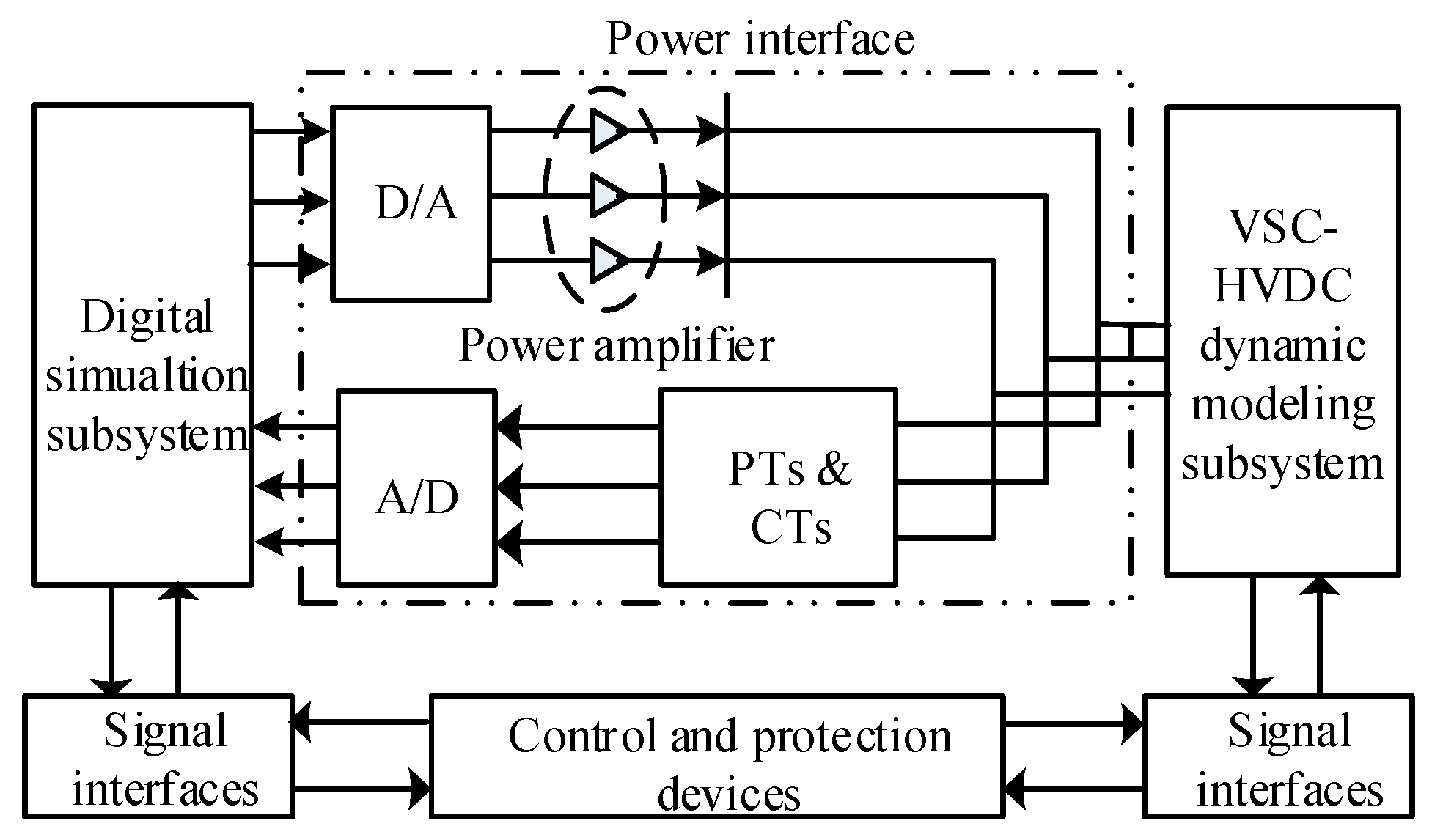
2.1. General Structure of the DPHS System

As shown in Figure 1, the DPHS system is generally structured by a digital simulation subsystem that simulates the real AC power system to which the VSC-HVDC connects, a physical dynamic modeling subsystem which is the real VSC-HVDC system in a reduced scale, the control and protection devices of the whole power system, and the power interface unit that plays a key role in the successful implementation of the DPHS system.
Only by designing the power interface unit elaborately to provide a two-way functionality, can the digital simulation subsystem and the physical dynamic modeling subsystem, which are distinctly different in operation principle, voltage/current levels and system nature (continuous vs. discrete), cooperate and interact with each other to behave precisely as the actual power system integrated with VSC-HVDC systems. That is on the one hand, the power amplifier of the power interface amplifies the analog signals which are converted by the D/A converter from the digital signals output from the digital simulation subsystem, thereby the physical dynamic modeling subsystem can operate as desired. On the other hand, the power interface unit samples the necessary signals of the physical dynamic modeling subsystem via the Potential Transformers (PTs) and Current Transformers (CTs) and converts them into digital signals by the embedded A/D converters, then transmits these signals to the digital simulation subsystem in time to prepare for the solution of the AC system in the next simulation time step.
We can learn from the previous explanation that plenty of factors may affect the performance of the power interface unit, and thus the operation the whole DPHS system; for example the conversion accuracy and speed of the A/D and D/A converter, and the measurement accuracy and response speed of the PTs and CTs. This paper regards the power amplifier as a delay link in the analysis of system stability and devotes itself to find an effective and practical algorithm in modeling the power interface to improve the stability of the DPHS system.

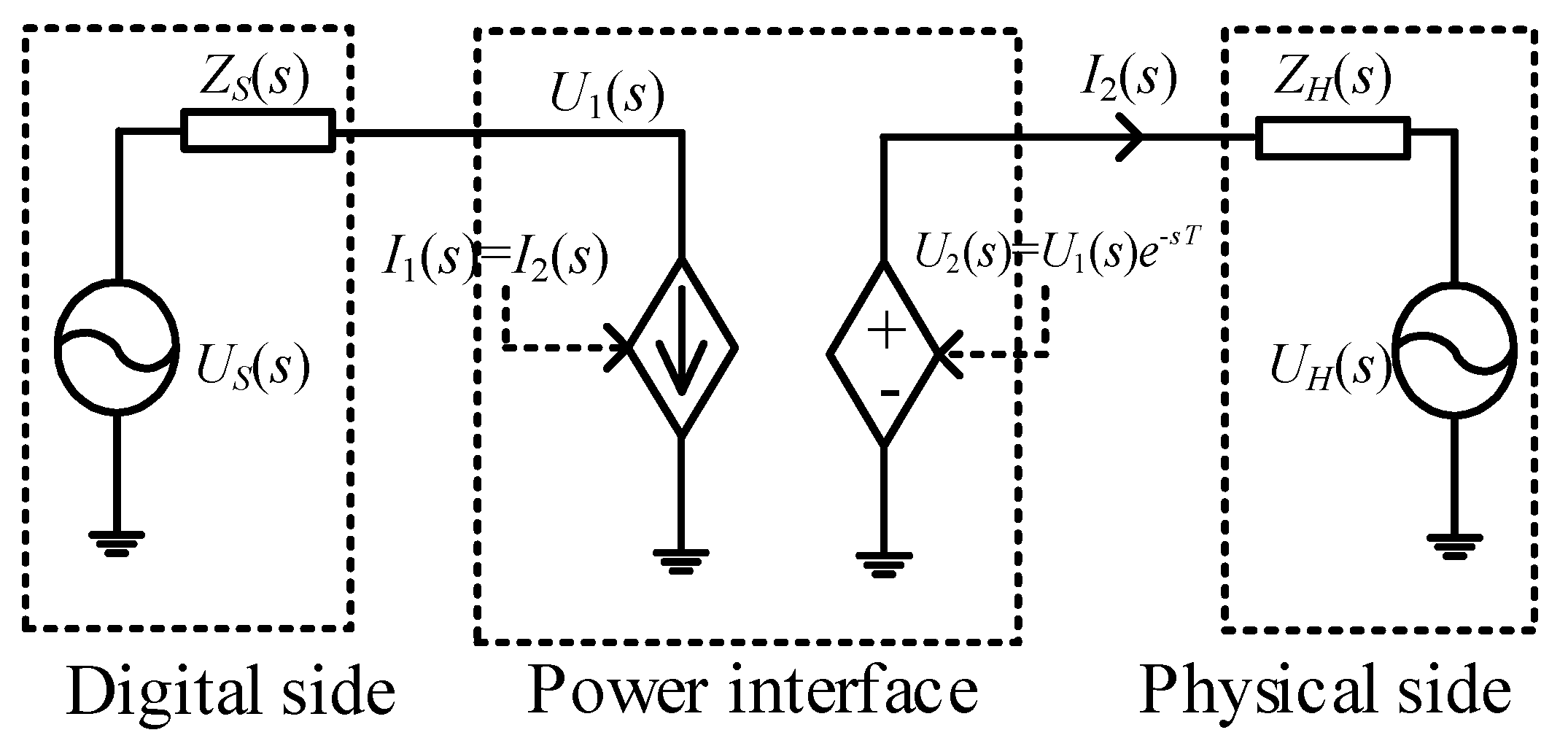
2.2. Current Modeling Method Based on ITM

The voltage-source-based version of the ITM algorithm, which has been widely applied in modelling the power interface of a hybrid simulation system [7,8,9,10,11,12], is chosen as the foundation in this paper to support the voltage source converters of the VSC-HVDC system. Figure 2 is the equivalent circuit of the DPHS system based on current voltage-source-based ITM method.
In Figure 2, US(s)/ZS(s) and UH(s)/ZH(s) are the equivalent voltage source/impedance of the digital and physical subsystem respectively. U1(s) and I1(s) are the voltage and current at the port of the digital subsystem interfacing with the power interface unit, U2(s) and I2(s) represent the actual output voltage and current of the power interface. The controlled current source, which is under the control of the sampled signal of I2(s), is used to model the remaining circuit of the DPHS besides the AC system in the digital simulation subsystem, while the controlled voltage source represents the power amplifier outputting voltage U2(s), which lags behind the control signal U2(s) in time by a constant of T.

2.3. System Stability Analysis of the Current ITM-Based Modeling Method

In this paper, we apply the s-domain stability analysis method to evaluate the stability of the DPHS system with a delay time introduced by the power interface unit. The discretization feature of the digital simulation process is bypassed.
With UH(s) = 0, the voltage U1(s) and U2(s) at digital and physical port of the power interface unit can be derived from Figure 2 as:
{ U 1 ( s ) = U S ( s ) I 1 ( s ) Z S ( s ) U 2 ( s ) = I 2 ( s ) Z H ( s )
The outputs of the controlled current and voltage source are, respectively:
{ U 2 ( s ) = U 1 ( s ) e s T I 1 ( s ) = I 2 ( s )
By combining the above two formulas, we can obtain:
U 2 ( s ) U S ( s ) = e s T 1 + Z S ( s ) Z H ( s ) e s T
The open loop transfer function of the system shown in Figure 2 can be solved from Formula (3) as:
G ( s ) = Z S ( s ) Z H ( s ) e s T
The condition in to guarantee the system stability can be deduced according to the Nyquist stability criterion as:
| Z S ( s ) Z H ( s ) | < 1
In equality (5) implies that the whole DPHS system is stable only when the amplitude of the equivalent impedance of the physical subsystem is larger than that of the digital subsystem. Therefore, to improve the stability of a DPHS system, we can increase |ZH(s)| and/or decrease |ZS(s)| by: (1) redesigning the physical subsystem. Obviously, this method has hardly any chance to be put into practice due to the fact that the involved possible additions and/or modifications of the main-circuit elements and the operation modes of the physical subsystem, just for the purpose of improving the stability of the DPHS system, are unacceptable. The scheme proposed in Reference [16] seems to be an exception in that the DPHS system is decoupled at the system-side of the converter transformer instead of the converter-side, thereby increasing |ZH(s)| and decreasing |ZS(s)| at the same time. However, this way is of a very poor practicability in that the investment and land occupation of the DPHS system are expected to increase dramatically when the converter transformers are implemented physically; (2) redesigning the simulation model in the digital subsystem. In theory, this way is more appreciated due to its obvious advantages of very easy implementation and convenient adjustment. Similarly, the part of the simulation model that represents the real AC power system cannot be modified for the purpose of stability improvement only, thus the controlled current source, which simulates the power interface burdened with the physical subsystem, is our last straw to clutch at.

3. Power Interface Modeling Method Based on Virtual Resistance Compensation

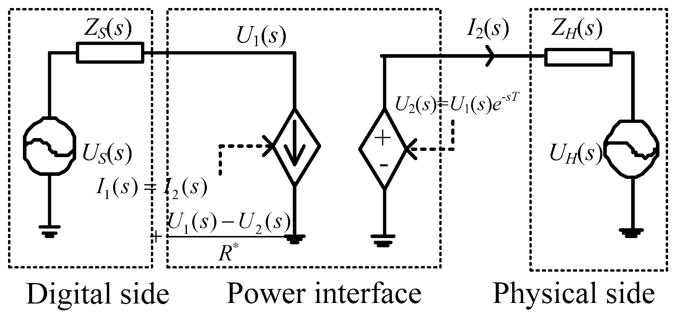
3.1. Principle of the Improved Modeling Method

Figure 3 illustrates the circuit of a DPHS system with our improved power interface model. We can see that the signal in controlling the controlled current source is updated by adding a current flowing through a virtual resistor R* to the output current of the power interface.
The outputs of the controlled current and voltage source in Figure 3 are respectively:
{ U 2 ( s ) = U 1 ( s ) e s T I 1 ( s ) = I 2 ( s ) + U 1 ( s ) U 2 ( s ) R *
The second equation in Formula (6) implies that the virtual resistor R* only functions when the time delay T is nonzero.
By combining Formulas (1) and (6), we can obtain:
U 2 ( s ) U S ( s ) = R * R * + Z S ( s ) e s T 1 + Z S ( s ) ( R * Z H ( s ) ) Z H ( s ) ( R * + Z S ( s ) ) e s T
The open loop transfer function of the system shown in Figure 3 can be derived according to the above equation as:
G ( s ) = Z S ( s ) ( R * Z H ( s ) ) Z H ( s ) ( R * + Z S ( s ) ) e s T
Then the stability condition of the DPHS system with the improved power interface model can be solved according to the Nyquist stability criterion as:
| Z S ( s ) ( R * Z H ( s ) ) Z H ( s ) ( R * + Z S ( s ) ) | = | Z S ( s ) Z H ( s ) | × | R * Z H ( s ) R * + Z S ( s ) | < 1
By comparing the two stability conditions expressed in Formulas (5) and (9) respectively, we can know that the stability of the DPHS system is indeed influenced by the simple method of introducing a virtual resistor R*, and if properly tuned, this virtual resistor will provide us with a cost-effective measure to achieve the goal of improving the stability of a DPHS system, or even stabilizing a DPHS system which is originally unstable.

3.2. System Stability Analysis

ZS(s) = sL1 + R1 and ZH(s) = sL2 + R2, respectively, and further assuming s = , we can obtain:
| ( R 1 + j ω L 1 ) ( R * R 2 j ω L 2 ) ( R 2 + j ω L 2 ) ( R * + R 1 + j ω L 1 ) | < 1
Formula (10) can be reformed by removing the sign for absolute value solution as:
( ω 2 L 1 2 + R 1 2 ω 2 L 2 2 R 2 2 ) 2 ( ω 2 L 1 2 R 2 + ω 2 L 2 2 R 1 + R 1 2 R 2 + R 1 R 2 2 ) R * < 1
Simplifying the above formula by recalling ZS(s) = sL1 + R1 and ZH(s) = sL2 + R2, we can obtain:
( | Z S ( s ) | 2 | Z H ( s ) | 2 ) R * < 2 ( R 2 | Z S ( s ) | 2 + R 1 | Z H ( s ) | 2 )
Several interesting conclusions regarding the system stability can be drawn from the analysis of Formula (12) as:
(1)
When |ZS(s)| < |ZH(s)|, we can know from Formulas (5) and (12) that both the DPHS systems adopting the voltage-source-type ITM method and our virtual resistance compensation modeling algorithm with R* > 0 are stable. Therefore, we can conclude that the system stability will not be degraded by the introduction of the virtual resistor with any positive value at least.
(2)
When |ZS(s)| > |ZH(s)|, the voltage-source-type ITM method fails to guarantee the stability of the DPHS system. While Formula (12) definitely informs us that the system stability can be recovered by just adding a virtual resistor into the power interface model, provided that the resistance satisfies:
R * < 2 ( R 2 | Z S ( s ) | 2 + R 1 | Z H ( s ) | 2 ) | Z S ( s ) | 2 | Z H ( s ) | 2

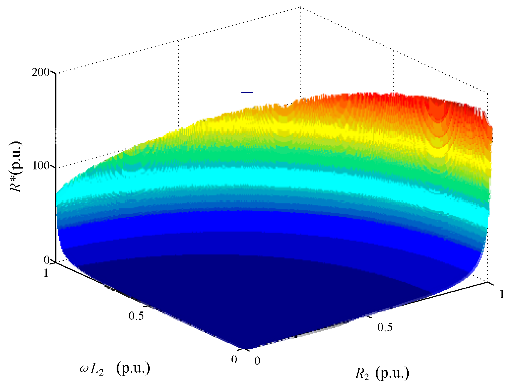
3.3. Tuning Method for the Virtual Resistance

In theory, the virtual resistor of a value that is much smaller than the right-side of the inequality (Equation (13)) is appreciated in that it can provide the DPHS system with a larger stability margin. While the second equation in Formula (6) indicates that due to the participation of the current in the virtual resistor, the behavior of the power interface burdened with the physical subsystem observed from the digital side (represented by I1(s)) deviates from its reality (represented by I2(s)), and this deviation tends to be larger with a smaller value of R*.
Therefore, to offer the DPHS system a simulation accuracy as high as possible under the premise of guaranteeing the system stability, R* is tuned to be of a value that satisfies Formula (13) in all the possible combinations of the impedance ZS(s) and ZH(s), that is,
R * = max   { min   [ 2 ( R 2 | Z S ( s ) | 2 + R 1 | Z H ( s ) | 2 ) | Z S ( s ) | 2 | Z H ( s ) | 2 ] }
For the DPHS of a bipolar VSC-HVDC system, the digital side equivalent impedance ZS(s) is of a constant value under steady operation and it can be obtained conveniently via the impedance scanning technology, while the impedance ZH(s) is variable due to the fast switching of the converters. Taking |ZH(s)| as the base value, Figure 4 shows the per-unit value of R* as a function of ZH(s) with R1 = 0.8 p.u.
Figure 4 informs us that R* should be of a smaller value for R2 and ωL2 with smaller values, thus the minimum value of the impedance of the physical subsystem is the key factor in determining the virtual impedance. In this paper, we solve this issue roughly according to the mono-polar AC equivalent circuit of the MMC shown in Figure 5.
In Figure 5, LT and L0 are the equivalent inductance of the converter transformer and the inductance in each arm of the converter, respectively. Rarm,jp and Rarm,jn,(j = a, b, c), which is of a time-invariant value, represents the resistance in the upper and lower arm of leg j of the monopole converter, respectively.
We consider the scenario that the DC bus of the converter is short-circuited to calculate the minimum value of |ZH(s)| from Figure 5 as:
{ R 2 , min = 1 2 NR ON L 2 , min = L T + L 0 2
where N is the number of the series modules in an arm and RON is the equivalent on-resistance of a module. For a VSC-HVDC with the bipolar arrangement, the values of R2,min and L2,min are half of those solved from Formula (15).

4. Simulation Verification

We corroborate the correctness and effectiveness of virtual-resistance-compensation-based modeling algorithm by carrying out plenty of simulations on the model shown in Figure 6 using PSCAD software.
The physical subsystem is characterized by a two-terminal true bipolar VSC-HVDC system with MMC-based converters, and the sub-module is established with the Thevenin equivalent model. Each AC terminal is connected to the corresponding AC power system realized in the digital subsystem through a power interface.
Table 1 summarizes the parameter values of the main circuit elements and settings of the simulation model.
The minimum values of R2 and L2 can be solved from Table 1 as: R2,min = (90 × 0.005)/4 = 0.1125 Ω and L2,min = 0.058 H.

4.1. Verification of the Virtual Resistance modeling Algorithm

Figure 7 illustrate the waveform of the physical subsystem voltage U2 for the original ITM-based power interface unit model.
As seen from Figure 7, when applying the original ITM to model the power interface unit, U2 begins to oscillate at about t = 0.05 s and the DPHS system will lose stability thereafter. The reason is that the system stability condition, i.e., Formula (5) has been violated since |ZS(s)|/|ZH(s)| = 1.05 > 1.
Substituting R2,min = 0.1125 Ω, L2,min = 0.058 H and ω = 100 π into Formula (14), we can obtain R* = 35 Ω, and the physical subsystem voltage U2 for our improved power interface unit model is shown in Figure 8.
The ‘original system’ refers to the simulation model of the actual MMC-HVDC project, i.e., the one in which the structure is similar to that shown in Figure 6 but without the two power interface models, and its simulation results are taken as the benchmarks in this paper.
Figure 8 shows that by improving the power interface model with the virtual resistance compensation, the DPHS system is stable and the waveform of the voltage U2 agrees well with that of the original system. These results validate the correctness of our improved ITM and the effectiveness of the parameter tuning method of the virtual resistance in guaranteeing the stability of the DPHS system.

4.2. Simulation Accuracy of the Virtual Resistance Modeling Algorithm

The following three indicators are used to evaluate the accuracy of a DPHS system in simulating the original system.
δ P = | P ref P P ref | × 100 %
δ V = | V ref V V ref | × 100 %
δ E = | E ref E E ref | × 100 %
where Pref/P, Vref/V and Eref/E are respectively the active power P of the power interface, the RMS value of the phase voltage U2 of the physical subsystem and the positive polar DC voltage E, of the original system/the DPHS system with our improved ITM, as shown in Figure 6. The variations of the relative simulation error δP, δV and δE are depicted in Figure 9.
We can learn from Figure 9 that for R* = 35 Ω, the relative errors δP, δV and δE are lower than 0.3%, 0.07% and 0.4% respectively. These results prove that by introducing a properly tuned virtual resistance into the model of the power interface, not only the stability of a DPHS system can be improved, but also a high simulation accuracy can be guaranteed.

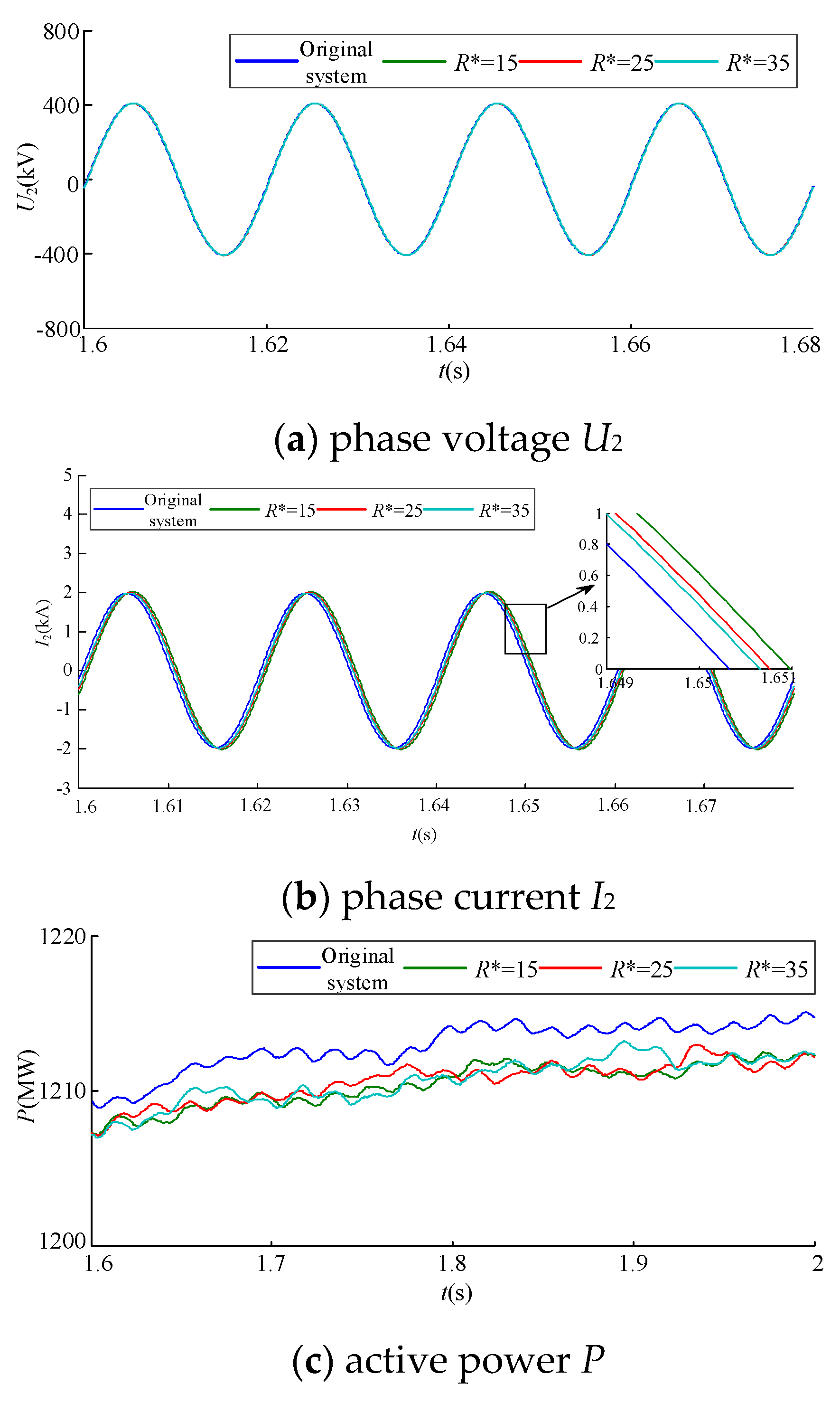
4.3. Simulation Accuracy for Different Values of the Virtual Impedance

Figure 10 shows the waveforms of the active power P, the phase voltage U2 and the power interface output current I2 in steady state for R* = 15 Ω, 25 Ω and 35 Ω.
We can learn that for R* with different values that all satisfy the stability condition (Equation (13)), the voltages at the port of the physical subsystem interfacing with the power interface unit are almost the same, as shown in Figure 10a. The active powers of the power interface unit shown in Figure 10b have similar values, which are lower than those of the original system. As seen from Figure 10b, the currents of the physical subsystem deviate slightly from that of the original system due to the insertion of the virtual resistance, and a smaller value of R* offers a larger time delay for the current in tracking its reference. These results prove that the virtual resistance being of a value that is as large as possible is preferred in guaranteeing a higher simulation accuracy for the DPHS system.

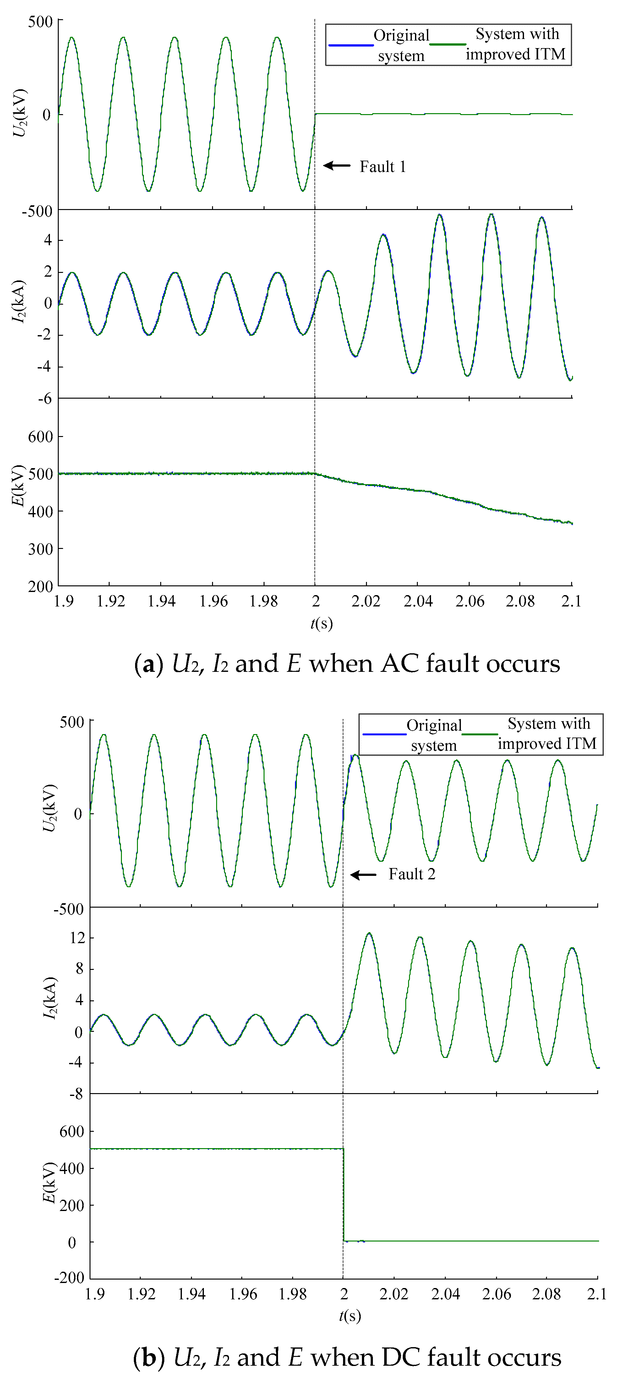
4.4. Verification of the Virtual Resistance Modeling Algorithm in the Transient Process

The simulation of AC and DC faults is carried out in PSCAD. Fault settings are (1) three-phase short-circuit grounding fault at bus 1; and (2) bipolar short-circuit fault at the middle of HVDC transmission line, the fault occurs in 2 s, and the simulation results are shown in Figure 11.
We can learn from Figure 11 that when an AC or a DC fault occurs, the hybrid simulation system with improved interface model can maintain stable operation. The maximum relative error of each index quantity during the transient process is given in Table 2.
We can learn from Table 2 that the method proposed in this paper can still guarantee the accuracy of the system in the transient process.

5. Conclusions

This paper carries out research on the modelling algorithm for the power interface unit of the DPHS system of a bipolar VSC-HVDC project. An improved version of the current ITM that is based on the virtual resistance compensation technology is proposed with the aim to improve the stability of the DPHS system. By comprehensively considering the system stability and simulation accuracy, the value of the virtual resistance is optimized according to the system stability criterion. Simulation results verify that the proposed modelling algorithm and virtual resistance tuning method for the power interface unit can effectively improve the stability and guarantee the high simulation accuracy of a DPHS system. Furthermore, its excellent advantage of very easy implementation provides a solid foundation for the research of the joint trial operation technology of the DPHS of a VSC-HVDC system.

Author Contributions

Conceptualization, J.L. and H.Z.; Methodology, J.L. and H.Z.; Software, J.L. and C.W.; Validation, H.Z., C.W. and X.L.; Formal Analysis, H.Z.; Investigation, J.Z.; Resources, J.Z.; Data Curation, X.L.; Writing-Original Draft Preparation, H.Z.; Writing-Review & Editing, J.L.; Visualization, J.L.; Supervision, J.L.; Project Administration, J.L.; Funding Acquisition, J.L.

Funding

This research and the APC were funded by the National Key Research and Development Program (2016YFB0900903) grant number 775 CHF.

Acknowledgments

The authors would like to thank all the members of the National Key Research and Development Program (2016YFB0900903), especially Zhou Wenjun and Liu Kaipei.

Conflicts of Interest

The authors declare no conflict of interest.

References

  1. Xiang, W.; Lin, W.; Xu, L.; Wen, J. Enhanced independent pole control of hybrid MMC-HVDC system. IEEE Trans. Power Deliv. 2018, 33, 861–872. [Google Scholar] [CrossRef]
  2. Guo, Y.F.; Gao, H.L.; Wu, Q.W.; Zhao, H.; Østergaard, J.; Shahidehpour, M. Enhanced voltage control of VSC-HVDC-connected offshore wind farms based on model predictive control. IEEE Trans. Sustain. Energy 2018, 9, 474–487. [Google Scholar] [CrossRef]
  3. Sanz, I.M.; Judge, P.D.; Spallarossa, C.E.; Chaudhuri, B.; Green, T.C. Dynamic overload capability of VSC HVDC interconnections for frequency support. IEEE Trans. Energy Convers. 2017, 32, 1544–1553. [Google Scholar] [CrossRef]
  4. Papaspiliotopoulos, V.A.; Korres, G.N.; Kleftakis, V.A.; Hatziargyriou, N.D. Hardware-In-the-Loop design and optimal setting of adaptive protection schemes for distribution systems with distributed generation. IEEE Trans. Power Deliv. 2015, 32, 393–400. [Google Scholar] [CrossRef]
  5. Kotsampopoulos, P.C.; Lehfuss, F.; Lauss, G.F.; Bletterie, B.; Hatziargyriou, N.D. The limitations of digital simulation and the advantages of PHIL testing in studying distributed generation provision of ancillary services. IEEE Trans. Ind. Electron. 2015, 62, 5502–5515. [Google Scholar] [CrossRef]
  6. Ren, W.; Sloderbeck, M.; Steurer, M.; Dinavahi, V.; Noda, T.; Filizadeh, S. Interfacing issues in real-time digital simulators. IEEE Trans. Power Deliv. 2011, 26, 1221–1230. [Google Scholar] [CrossRef]
  7. Kuffel, R.; Wierckx, R.P.; Duchen, H.; Lagerkvist, M.; Wang, X.; Forsyth, P.; Holmberg, P.; Chevrefils, A.R.; Matar, M.; Iravani, R.; et al. Expanding an analogue HVDC simulator’s modelling capability using a real-time digital simulator (RTDS). In Proceedings of the First International Conference on Digital Power System Simulators (ICDS’95), College Station, TX, USA, 5–7 April 1995; IEEE: New York, NY, USA, 1995; pp. 199–204. [Google Scholar]
  8. Hu, Y.; Zhang, P.; Fang, C.; Bao, H. Power hardware-in-the-loop simulation system: Part one characteristics of interface algorithms. Autom. Electr. Power Syst. 2013, 37, 36–41. [Google Scholar]
  9. Hong, M.; Horie, S.; Miura, Y.; Ise, T.; Dufour, C. A method to stabilize a power hardware-in-the-loop simulation of inductor coupled system. In Proceedings of the International Conference on Power System Transients, Seoul, Korea, 27–29 December 2009; pp. 1–7. [Google Scholar]
  10. Lauss, G.; Lehfuß, F.; Viehweider, A.; Strasser, T. Power hardware in the loop simulation with feedback current filtering for electric systems. In Proceedings of the Conference on IEEE Industrial Electronics Society (IECON 2011), Melbourne, Australia, 7–10 November 2011; IEEE: New York, NY, USA, 2011; pp. 3725–3730. [Google Scholar]
  11. Yoo, I.D.; Gole, A.M. Compensating for interface equipment limitations to improve simulation accuracy of real-time Power Hardware in Loop simulation. IEEE Trans. Power Deliv. 2012, 27, 1284–1291. [Google Scholar] [CrossRef]
  12. Xin, Y.; Jiang, S.; Li, G.; Wang, L. Review on interface algorithms of power hardware-in-the-loop simulation for power systems. Autom. Electr. Power Syst. 2016, 40, 159–167. [Google Scholar]
  13. Paran, S.; Edrington, C.S.; Vural, B. Investigation of HIL interfaces in nonlinear load studies. In Proceedings of the North American Power Symposium, Champaign, IL, USA, 9–11 September 2012; IEEE: New York, NY, USA, 2012; pp. 1–6. [Google Scholar]
  14. Paran, S.; Edrington, C.S. Improved power hardware in the loop interface methods via impedance matching. In Proceedings of the Electric Ship Technologies Symposium, Arlington, VA, USA, 22–24 April 2013; IEEE: New York, NY, USA, 2013; pp. 342–346. [Google Scholar]
  15. Paran, S.; Fleming, F.; Li, D.; Edrington, C.S. Utilization of adaptive PHIL interfaces for harmonic load cases. In Proceedings of the IEEE Conference of the Industrial Electronics Society (IECON 2014), Dallas, TX, USA, 30 October–1 November 2014; IEEE: New York, NY, USA, 2015; pp. 3803–3808. [Google Scholar]
  16. Lin, C.Q.; Jiang, S.Q.; Chen, H.H. An improved interface algorithm of power hardware-in-the-loop simulation for MMC-HVDC. J. Northeast Dianli Univ. 2016, 36, 1–6. [Google Scholar]
Figure 1. General structure of a digital-physical hybrid simulation (DPHS) system.
Electronics 07 00333 g001
Figure 2. Equivalent circuit of the DPHS based on a voltage-source-ITM (ideal transformer method).
Electronics 07 00333 g002
Figure 3. Equivalent circuit of the DPHS based on the improved power interface model.
Electronics 07 00333 g003
Figure 4. The relationship between R* and ZH (p.u.).
Electronics 07 00333 g004
Figure 5. Equivalent circuit of an modular multilevel converter (MMC).
Electronics 07 00333 g005
Figure 6. Structure of the simulation model.
Electronics 07 00333 g006
Figure 7. Waveform of the voltage for the original ITM interface model.
Electronics 07 00333 g007
Figure 8. Waveform of the voltage for the improved ITM interface model.
Electronics 07 00333 g008
Figure 9. Relative errors of P, V and E.
Electronics 07 00333 g009
Figure 10. Simulation results comparison for different values of R*. (a) phase voltage U2, (b) phase current I2, (c) active power P.
Electronics 07 00333 g010
Figure 11. Simulation results in the transient process. (a) U2, I2 and E when AC fault occurs. (b) U2, I2 and E when DC fault occurs.
Electronics 07 00333 g011
Table 1. Elements parameter values and simulation model settings.
ParameterValue
AC systemsRated line-to-line voltage500 kV
Rs1 and Rs11.2 Ω
Ls1 and Ls10.06 H
Converter transformersRated capacity1500 MVA
Transformation ratio500/270
LT0.1 p.u.
ConvertersL00.1 H
N90
RON0.005 Ω
DC systemRated DC voltage±500 kV
Rated transmission capacity1200 MVA
Power interfaceT50 μs
Time delay of A/D and CTs0 μs
Simulation modelSimulation step size10 μs
Simulation time3 s
Table 2. Simulation errors in the transient process.
δP (%)δV (%)δE (%)
Normal0.300.070.40
Fault 10.2800.53
Fault 20.440.230

