Power-Efficient Random Access Design for Machine Type Communication


Abstract
:1. Introduction
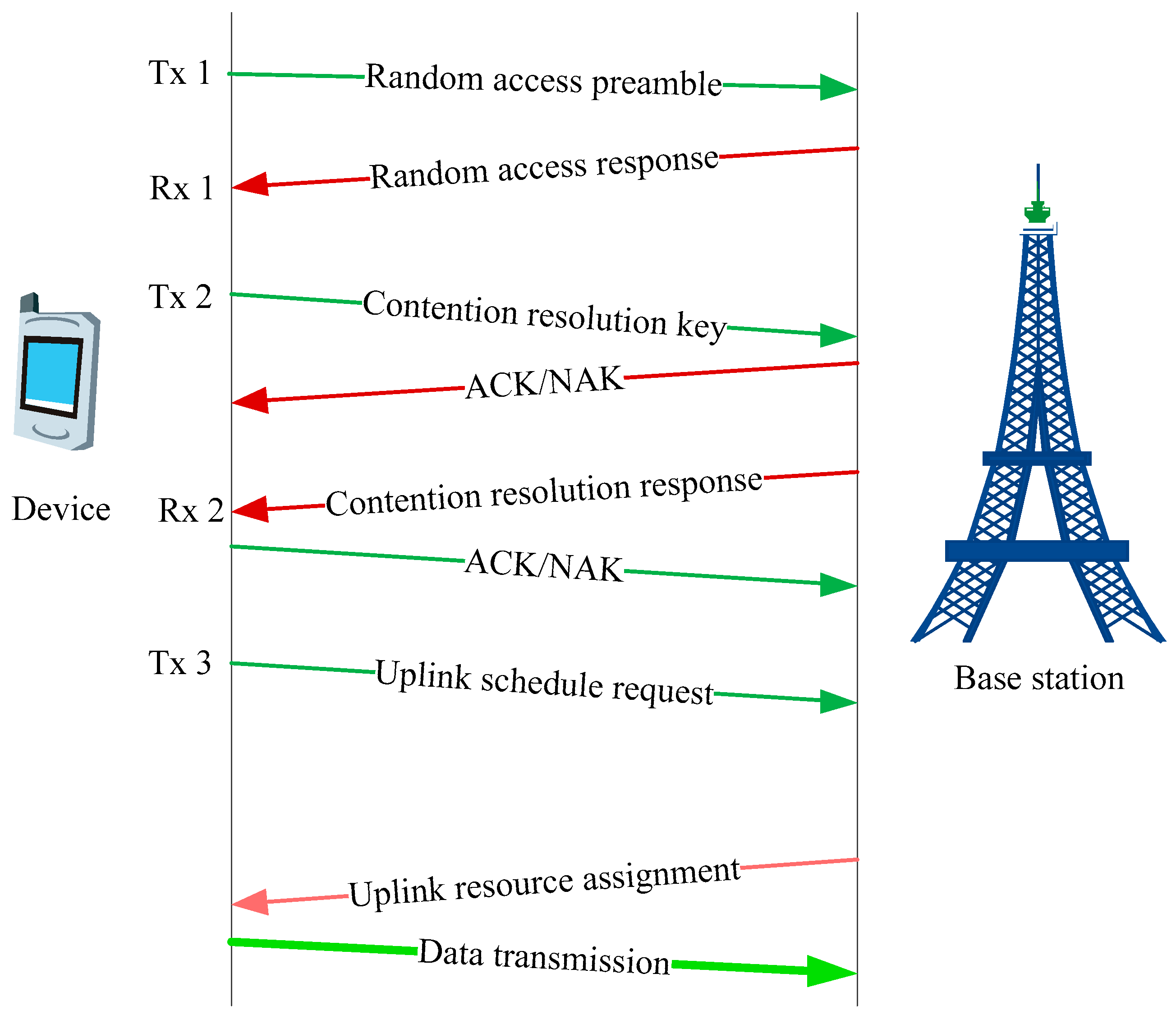
2. LTE Random Access
3. LTE-nMTC Random Access Design
3.1. Power Consumption Analysis
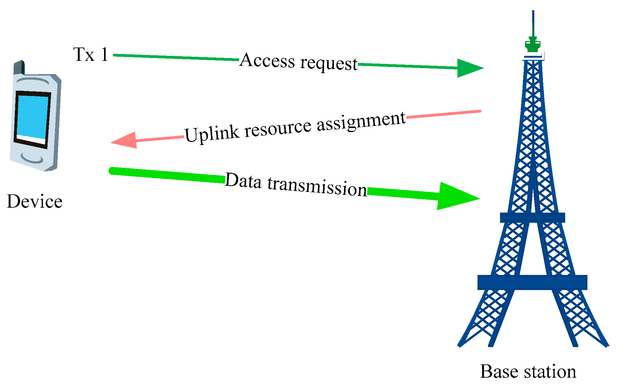
3.2. Simplified Random Access Signaling
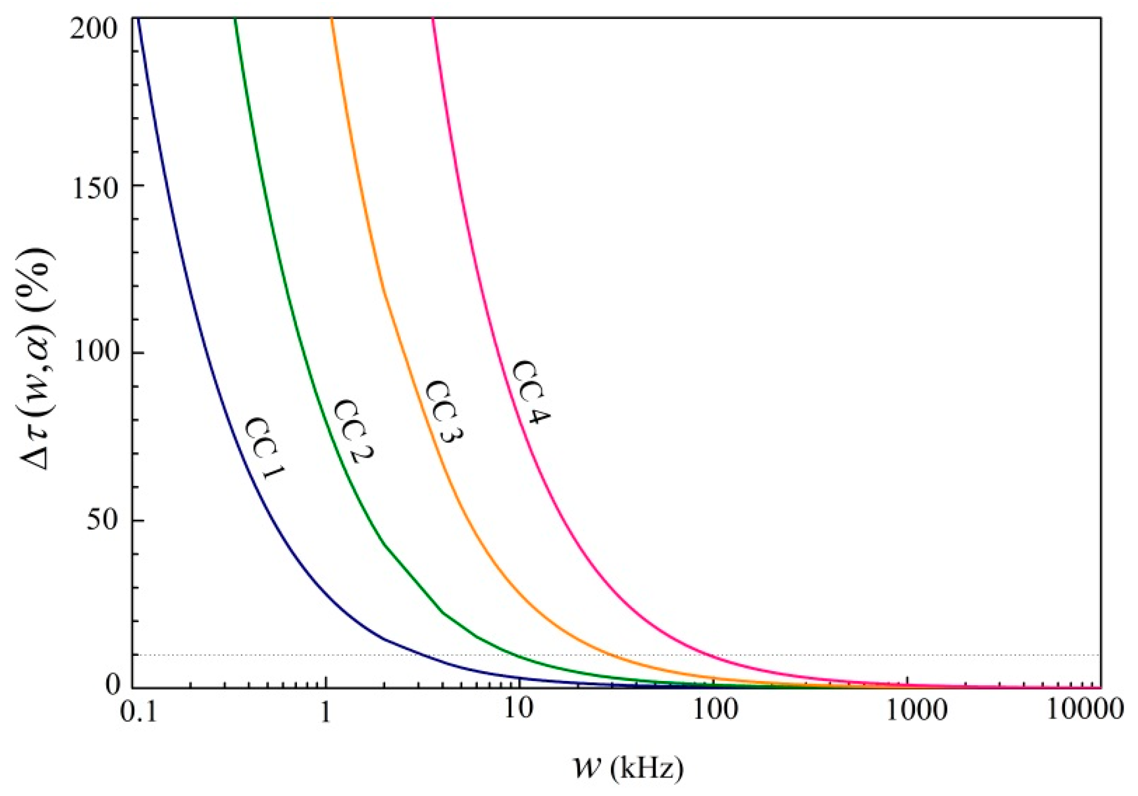
3.3. Effective Bandwidth and Optimal Resource Configuration
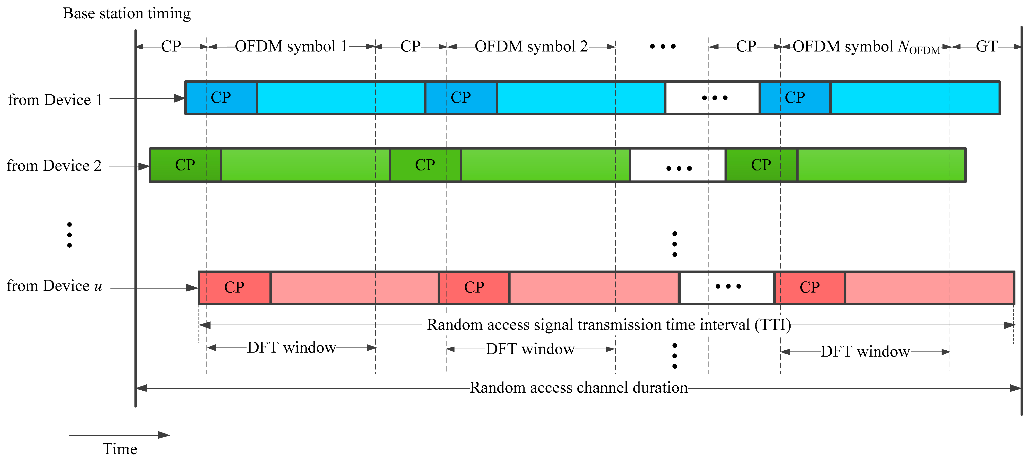
3.4. Physical Layer Mapping and Timing Estimation
4. Link Budget Analysis and Simulation Results
4.1. Link Budget Analysis
4.2. Simulation Results
4.3. Support for Larger Cells
4.4. Random Access Capacity
5. Conclusions
Author Contributions
Funding
Conflicts of Interest
References
- Rajpal, J. Framework for enabling machine-type communication services. IET Wirel. Sens. Syst. 2017, 7, 9–14. [Google Scholar] [CrossRef]
- Xia, N.; Chen, H.; Yang, C. Radio resource management in Machine-to-Machine communications—A survey. IEEE Commun. Surv. Tutor. 2018, 20, 791–828. [Google Scholar] [CrossRef]
- Ali, M.S.; Hossain, E.; Kim, D.I. LTE/LTE-A random access for massive Machine-Type Communications in Smart Cities. IEEE Commun. Mag. 2017, 55, 76–83. [Google Scholar] [CrossRef]
- Wu, G.; Talwar, S.; Johnsson, K.; Himayat, N.; Johnson, K.D. M2M: From mobile to embedded Internet. IEEE Commun. Mag. 2011, 49, 36–43. [Google Scholar]
- Knight, M. Wireless security—How safe is Z-wave? Comput. Control Eng. J. 2006, 17, 18–23. [Google Scholar] [CrossRef]
- SIGFOX Whitepaper. SIGFOX—One Network a Billion Dreams. Available online: https://docslide.us/technology/sigfox-whitepaper.html (accessed on 8 October 2018).
- Sornin, N. LoRaWAN Specfication. Available online: https://lora-alliance.org/resource-hub (accessed on 8 October 2018).
- Weightless Specfication. Available online: http://www.weightless.org/about/weightless-specification (accessed on 8 October 2018).
- Lippuner, S.; Weber, B.; Salomon, M.; Korb, M.; Huang, Q. EC-GSM-IoT network synchronization with support for large frequency offsets. In Proceedings of the 2018 IEEE Wireless Communications and Networking Conference (WCNC), Barcelona, Spain, 15–18 April 2018; pp. 1–6. [Google Scholar]
- Hoglund, A. Overview of 3GPP release 14 enhanced NB-IoT. IEEE Netw. 2017, 31, 16–22. [Google Scholar] [CrossRef]
- Tsiropoulou, E.E.; Katsinis, G.K.; Vamvakas, P.; Papavassiliou, S. Efficient uplink power control in multi-service two-tier femtocell networks via a game theoretic approach. In Proceedings of the 2013 IEEE 18th International Workshop on Computer Aided Modeling and Design of Communication Links and Networks (CAMAD), Berlin, Germany, 25–27 September 2013; pp. 104–108. [Google Scholar]
- Tsiropoulou, E.E.; Katsinis, G.K.; Filios, A.; Papavassiliou, S. On the Problem of Optimal Cell Selection and Uplink Power Control in Open Access Multi-service Two-Tier Femtocell Networks. In Proceedings of the 2014 Ad-Hoc, Mobile, and Wireless Networks (ADHOC-NOW), Benidorm, Spain, 22–27 June 2014; pp. 114–127. [Google Scholar]
- Zahir, T.; Arshad, K.; Nakata, A.; Moessner, K. Interference Management in Femtocells. IEEE Commun. Surv. Tutor. 2013, 15, 293–311. [Google Scholar] [CrossRef] [Green Version]
- Chandrasekhar, V.; Andrews, J.G.; Muharemovic, T.; Shen, Z.; Gatherer, A. Power control in two-tier femtocell networks. IEEE Trans. Wirel. Commun. 2009, 8, 4316–4328. [Google Scholar] [CrossRef] [Green Version]
- Li, L.; Xu, C.; Tao, M. Resource Allocation in Open Access OFDMA Femtocell Networks. IEEE Wirel. Commun. Lett. 2012, 1, 625–628. [Google Scholar] [CrossRef]
- 3GPP. Technical Specification Group Services and System Aspects System Improvements for Machine-Type Communications (MTC) (Release 11). TS 23.888, ver.11.0.0. March 2013. Available online: ftp://3gpp.org/Specs/2013-03/Rel-11/23_series/ (accessed on 8 October 2018).
- 3GPP. Technical Specification Group Services and System Aspects Service Requirements for Machine-Type Communications (MTC) Stage 1 (Release 13). TR 22.368, ver.13.1.0. December 2014. Available online: ftp://3gpp.org/Specs/2014-12/Rel-13/22_series/ (accessed on 8 October 2018).
- 3GPP. Technical Specification Group Radio Access Network Evolved Universal Terrestrial Radio Access (E-UTRA) Physical Channels And Modulation (Release 12). TS 36.211, ver.12.4.0. December 2014. Available online: ftp://3gpp.org/Specs/2014-12/Rel-12/36_series/ (accessed on 8 October 2018).
- Balasubramanya, N.M.; Lampe, L.; Vos, G.; Bennett, S. On timing reacquisition and Enhanced Primary Synchronization Signal (ePSS) design for energy efficient 3GPP LTE MTC. IEEE Trans. Mob. Comput. 2017, 16, 2292–2305. [Google Scholar] [CrossRef]
- Holma, H.; Toskala, A. WCDMA for UMTS-HSPA Evolution and LTE.; John Wiley & Sons: New York, NY, USA, 2007. [Google Scholar]
- Zou, J.; Yu, H.; Miao, W.W.; Jiang, C.L. Packet-Based preamble design for random access in massive IoT communication systems. IEEE Access. 2017, 5, 11759–11767. [Google Scholar] [CrossRef]
- Yang, W.; Wang, M.; Zhang, J.; Zou, J.; Hua, M.; Xia, T.; You, X. Narrowband wireless access for low-power massive Internet of Things: A bandwidth perspective. IEEE Wirel. Commun. Mag. 2017, 99, 2–9. [Google Scholar] [CrossRef]
- 3GPP. Technical specification group radio access network Evolved Universal Terrestrial Radio Access (E-UTRA) physical channels and modulation (Release 14). TS 36.211, ver.14.4.0. September 2017. Available online: ftp://3gpp.org/Specs/2017-09/Rel-14/36_series/ (accessed on 8 October 2018).
- Tarik, T.; Andreas, K. Machine type communications in 3GPP networks potential, challenges, and solutions. IEEE Commun. Mag. 2012, 50, 178–184. [Google Scholar]
- 3GPP. Technical Specification Group Radio Access Network Study on Provision of Low-Cost Machine-Type Communications (MTC) User Equipment (Device) Based on LTE (Release 12). TR 36.888, ver.12.0.0. June 2013. Available online: ftp://3gpp.org/Specs/2013-06/Rel-12/36_series/ (accessed on 8 October 2018).
- Duan, S.; Shah-Mansouri, V.; Wang, Z.; Wong, V.W. D-ACB: Adaptive congestion control algorithm for bursty M2M traffic in LTE networks. IEEE Trans. Veh. Technol. 2016, 65, 9847–9861. [Google Scholar] [CrossRef]


| 4 (140 dB) | 3 (145 dB) | 2 (150 dB) | 1 (155 dB) | |
|---|---|---|---|---|
| Effective bandwidth(kHz) | 94 | 30 | 9 | 3 |
| Extra transmission time(%) | 10 | |||
| 4 (140 dB) | 3 (145 dB) | 2 (150 dB) | 1 (155 dB) | ||||
|---|---|---|---|---|---|---|---|
| TDM channels | 1 | 36 | 1 | 12 | 1 | 3 | 1 |
| Optimal bandwidth(kHz) | 12 | 90 | 9 | 30 | 6 | 9 | 3 |
| Channel bandwidth(kHz) | 12 | 90 | 9 | 30 | 6 | 9 | 3 |
| Number of subcarriers per channel | 4 | 30 | 3 | 10 | 2 | 3 | 1 |
| Total channels | 15 | 72 | 20 | 72 | 30 | 60 | 60 |
| Time penalty(%) | 130 | 9 | 60 | 9 | 27 | 11 | 10 |
| 4 (140 dB) | 3 (145 dB) | 2 (150 dB) | 1 (155 dB) | ||||
|---|---|---|---|---|---|---|---|
| TDM channels | 1 | 36 | 1 | 12 | 1 | 3 | 1 |
| Optimal bandwidth(kHz) | 12 | 90 | 9 | 30 | 6 | 9 | 3 |
| Channel bandwidth(kHz) | 12 | 90 | 9 | 30 | 6 | 9 | 3 |
| Number of subcarriers per channel | 4 | 30 | 3 | 10 | 2 | 3 | 1 |
| Total channels | 90 | 432 | 120 | 432 | 180 | 360 | 360 |
| Time penalty(%) | 125 | 9 | 59 | 8 | 26 | 10 | 10 |
| 4 (140 dB) | 3 (145 dB) | 2 (150 dB) | 1 (155 dB) | |||
|---|---|---|---|---|---|---|
| (dB) | LTE-nMTC | Tx1 | 0 | 0 | 0 | 0 |
| LTE-eMTC | Tx 1 | −11 | −16 | −21 | −26 | |
| Tx (2, 3) | −4 | −9 | −14 | −19 | ||
| Rx (1, 2) | 1 | −4 | −9 | −14 | ||
| 4 (140 dB) | 3 (145 dB) | 2 (150 dB) | 1 (155 dB) | |||
|---|---|---|---|---|---|---|
| TTI (sec) | LTE-nMTC | Tx1 | 0.0074 (5 symbol groups) | 0.0221 (12 symbol groups) | 0.09945 (54 symbol groups) | 0.2578 (140 symbol groups) |
| LTE-eMTC | Tx1 | 0.002 | 0.007 | 0.03 | 0.08 | |
| Rx1 | 0.116 | 0.274 | 0.638 | 1.564 | ||
| Tx2 | 0.008 | 0.045 | 0.2 | 0.85 | ||
| Rx2 | 0.011 | 0.034 | 0.138 | 0.574 | ||
| Tx3 | 0.001 | 0.008 | 0.06 | 0.13 | ||
© 2018 by the authors. Licensee MDPI, Basel, Switzerland. This article is an open access article distributed under the terms and conditions of the Creative Commons Attribution (CC BY) license (http://creativecommons.org/licenses/by/4.0/).
Share and Cite
Yu, H.; Zou, J.; Xu, C. Power-Efficient Random Access Design for Machine Type Communication. Electronics 2018, 7, 286. https://doi.org/10.3390/electronics7110286
Yu H, Zou J, Xu C. Power-Efficient Random Access Design for Machine Type Communication. Electronics. 2018; 7(11):286. https://doi.org/10.3390/electronics7110286
Chicago/Turabian StyleYu, Hai, Jun Zou, and Chen Xu. 2018. "Power-Efficient Random Access Design for Machine Type Communication" Electronics 7, no. 11: 286. https://doi.org/10.3390/electronics7110286
APA StyleYu, H., Zou, J., & Xu, C. (2018). Power-Efficient Random Access Design for Machine Type Communication. Electronics, 7(11), 286. https://doi.org/10.3390/electronics7110286