1. Introduction
The rapid development of electric mobility has intensified the need for charging solutions that are not only energy-efficient, but also convenient, reliable, and suitable for seamless integration into future transport infrastructure. In this context, wireless power transfer (WPT) has emerged as a promising alternative to conventional plug-in charging because it eliminates exposed conductive interfaces, improves user comfort, and enables a higher degree of charging automation. In electric-vehicle applications, wireless charging can also reduce vulnerability to environmental conditions, mechanical wear, vandalism, and user-dependent charging behavior, while supporting more flexible infrastructure deployment in private, public, and transit environments [
1,
2,
3].
Among the different wireless energy-transfer approaches, near-field inductive and resonant-inductive techniques are the most suitable for electric vehicles because they can deliver useful power levels over practical air gaps with comparatively high efficiency. In their simplest form, such systems operate through magnetic coupling between a transmitting coil and a receiving coil, similarly to a loosely coupled transformer [
4,
5]. However, unlike conventional transformers, EV charging systems usually operate with significant air gaps, limited magnetic coupling, and possible lateral misalignment between the primary and secondary pads. For that reason, the design of the magnetic coupler, the choice of resonant compensation, and the tuning of the operating frequency become critical factors that directly influence power-transfer capability, efficiency, and system stability. General WPT reviews also show that although many transmission methods exist, electromagnetic induction and resonance-enhanced inductive transfer remain the most practical options for short- and medium-range high-power applications [
6,
7,
8].
Existing research and industrial developments confirm the strong potential of inductive WPT for both stationary and dynamic electric-vehicle charging. Stationary systems are intended for applications such as home charging, parking areas, depots, and opportunity charging at stops, where the vehicle is positioned over a ground pad and energy is transferred through the vehicle-mounted pickup [
9,
10]. Dynamic or on-route charging extends this concept by energizing road-embedded transmitting structures so that vehicles can receive power while moving or while passing over energized segments. Such an approach has the potential to reduce charging downtime, alleviate range anxiety, and decrease the need for oversized battery packs [
11,
12,
13]. Previous developments reported in the literature include stationary commercial pads, public-transport charging installations, and concepts for online electric vehicles and segmented road-powered systems, demonstrating that both charging modes are technically feasible and highly relevant for future transport systems.
Despite this progress, several engineering challenges still limit the broader deployment of inductive EV charging systems. A recurring issue is the strong dependence of efficiency on the coupling factor between the transmitting and receiving coils. As the air gap increases or the relative alignment worsens, the coupling factor decreases and the transfer efficiency drops accordingly [
14,
15]. The geometry of the coils, the number of turns, the magnetic-core arrangement, and the shielding concept therefore play a decisive role in overall system performance. At the same time, the power-electronic interface must provide high-frequency excitation with acceptable switching losses and controllable operating conditions, while the resonant network must maintain efficient power transfer under realistic loading and geometric constraints. Prior studies have shown that impedance matching and resonant tuning can significantly improve transfer performance, but practical optimization remains strongly dependent on the intended application and package constraints [
16,
17].
Another important challenge is electromagnetic safety in the occupied area around the charging system. Because EV wireless chargers rely on alternating magnetic fields, their design must account not only for transferred power and efficiency, but also for magnetic-field leakage and exposure in the vicinity of the vehicle and infrastructure [
18,
19,
20]. This requirement becomes even more important when a system is intended for real deployment scenarios, including public-access charging areas and on-route applications. Consequently, a practically relevant EV WPT study should not stop at conceptual circuit design, but should also include prototype-level validation and assessment of field levels around the charging platform. The literature contains examples of systems designed for improved field distribution and low electromagnetic exposure, which highlights the need to integrate performance optimization with safety-oriented verification [
21,
22].
In this context, the main gap addressed by the present work is the limited number of studies that combine magnetic-coupler realization, resonant power-stage integration, prototype-level validation, and occupied-area magnetic-field assessment within one application-oriented study of static EV wireless charging.
The contribution of this paper is not a general review of EV wireless charging technologies, but the design and prototype-level validation of a static WPT platform. The main contributions are as follows: (1) development of a practical coupled magnetic/electrical design procedure for a 35 kW-class inductive charging platform; (2) realization of a Tx/Rx magnetic coupler with reported dimensions, inductance, and coupling characteristics; (3) prototype-level validation of the implemented platform at a nominal 30 kW operating level under reported static charging conditions; and (4) representative occupied-area magnetic-field assessment. Dynamic or on-route charging is not experimentally validated in the present work and is discussed only as a possible direction for future extension.
2. Related Works
Wireless power transfer for electric vehicles has evolved from a primarily exploratory topic into a mature research field with clearly differentiated directions, including system-level reviews, resonant converter studies, magnetic-coupler optimization, prototype demonstrations, and safety- or standards-oriented investigations. Across this body of work, near-field inductive and resonant-inductive approaches remain the most practically relevant for EV charging because they provide a favorable compromise among transferred power, transfer distance, implementation maturity, and packaging feasibility [
3,
4,
5,
6,
7,
11,
23,
24,
25].
A substantial part of the literature focuses on electrical architecture and resonant compensation. These studies address converter topologies, resonant-network selection, operating-frequency control, impedance matching, and the interaction between compensation strategy and transferred power [
11,
12,
13,
14]. Their contribution is essential for understanding the behavior of high-frequency EV charging systems, but such works often place less emphasis on the simultaneous optimization of the magnetic structure, the physical implementation constraints, and the occupied-area field distribution [
26,
27,
28].
Another major research direction concerns the magnetic coupler itself. Published studies investigate coil geometry, ferrite arrangement, shielding, misalignment tolerance, leakage-field reduction, and coupling-factor improvement under constrained air gaps and realistic packaging conditions [
29,
30,
31]. These contributions are especially important because the coupler directly determines the achievable power density, efficiency, field distribution, and tolerance to installation inaccuracies [
30,
31,
32]. However, many of these studies optimize magnetic performance indicators in relative isolation, without carrying the design through to a fully integrated power-stage implementation and prototype-level validation [
32,
33,
34,
35].
Experimental and application-oriented publications have further demonstrated the feasibility of both stationary and dynamic EV charging. The literature includes laboratory demonstrators, public-transport charging systems, segmented transmitting structures, and roadway-oriented dynamic charging concepts [
36,
37,
38,
39,
40]. These studies confirm the technological relevance of both static and on-route charging modes, but they often emphasize infrastructure concepts, moving-vehicle operation, or proof-of-concept functionality rather than a unified design route that consistently links coupler design, converter integration, and safety-oriented field verification.
In parallel with purely technical developments, the field has increasingly incorporated safety, interoperability, and standardization requirements. Safety-focused studies and broader system-level analyses highlight that EV wireless charging must be evaluated not only in terms of power transfer and efficiency, but also in terms of electromagnetic exposure, installation conditions, alignment reproducibility, and infrastructure compatibility [
18,
19,
20,
21,
22]. This evolution is also reflected in normative documents such as IEC 61980 Parts 1–3 [
41,
42,
43], IEC PAS 61980-5 [
44], ISO 19363 [
45], SAE J2954 [
46], and the ICNIRP exposure guidelines [
47,
48], which collectively frame wireless charging as a deployment-oriented engineering system rather than as an isolated converter or magnetic-coupler problem.
Overall, the reviewed literature shows substantial progress in resonant converter design, magnetic-coupler optimization, prototype realization, dynamic charging concepts, and standards-oriented safety assessment. At the same time, these research directions are often treated separately. In this context, the present study is positioned as an application-oriented contribution that integrates magnetic-coupler design, resonant power-stage realization, prototype-level static validation, and occupied-area magnetic-field assessment within one experimentally supported workflow for static EV wireless charging. Possible extension toward on-route charging is discussed only as future work.
3. System Concept and Operating Principle
3.1. Overall Architecture of the Wireless Charging System
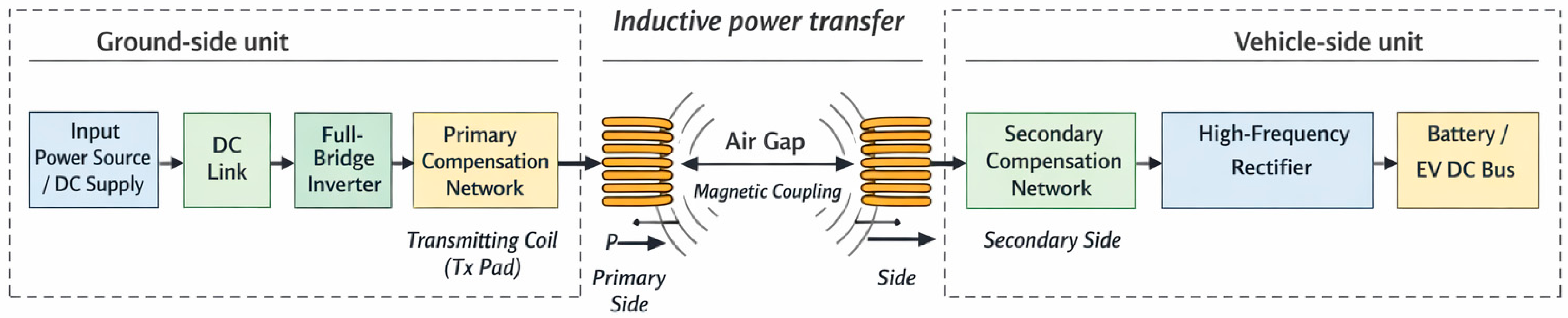
The proposed charger is organized as a ground-side transmitting unit, a vehicle-side receiving unit, and the associated power-electronic interface. On the primary side, a DC source feeds a full-bridge inverter and the resonant compensation network, which excite the transmitting pad at high frequency. On the secondary side, the receiving pad, compensation stage, rectifier, and DC interface deliver power to the vehicle load. In functional terms, the whole system behaves as a loosely coupled high-frequency transformer with a significant air gap and non-ideal magnetic coupling.
The developed platform is intended for static wireless charging and was experimentally validated under static operating conditions. From an engineering perspective, the proposed architecture belongs to the 35 kW-class, while the realized laboratory prototype was validated at a nominal 30 kW operating level, with peak capability up to 45 kW for 1 min. The primary power stage is based on a full-bridge inverter topology designed for operation in the reported low-tens-of-kHz range. The overall system concept links high-frequency power conversion, resonant compensation, and optimized contactless magnetic coupling for practical EV charging applications across air gaps up to about 100 mm.
The overall architecture of the proposed wireless power transfer charging system is illustrated in
Figure 1. The platform is organized into two main subsystems: the ground-side power unit and the vehicle-side receiving unit. Energy is transferred wirelessly between the transmitting and receiving coils through inductive coupling across an air gap.
On the ground side, the electrical energy provided by the input power source is first conditioned through a DC link stage and then converted into high-frequency alternating voltage by a full-bridge inverter. The generated high-frequency current excites the primary resonant compensation network and the transmitting coil (Tx pad), producing a time-varying magnetic field in the vicinity of the charging platform. This alternating magnetic field forms the basis of the inductive wireless power transfer mechanism.
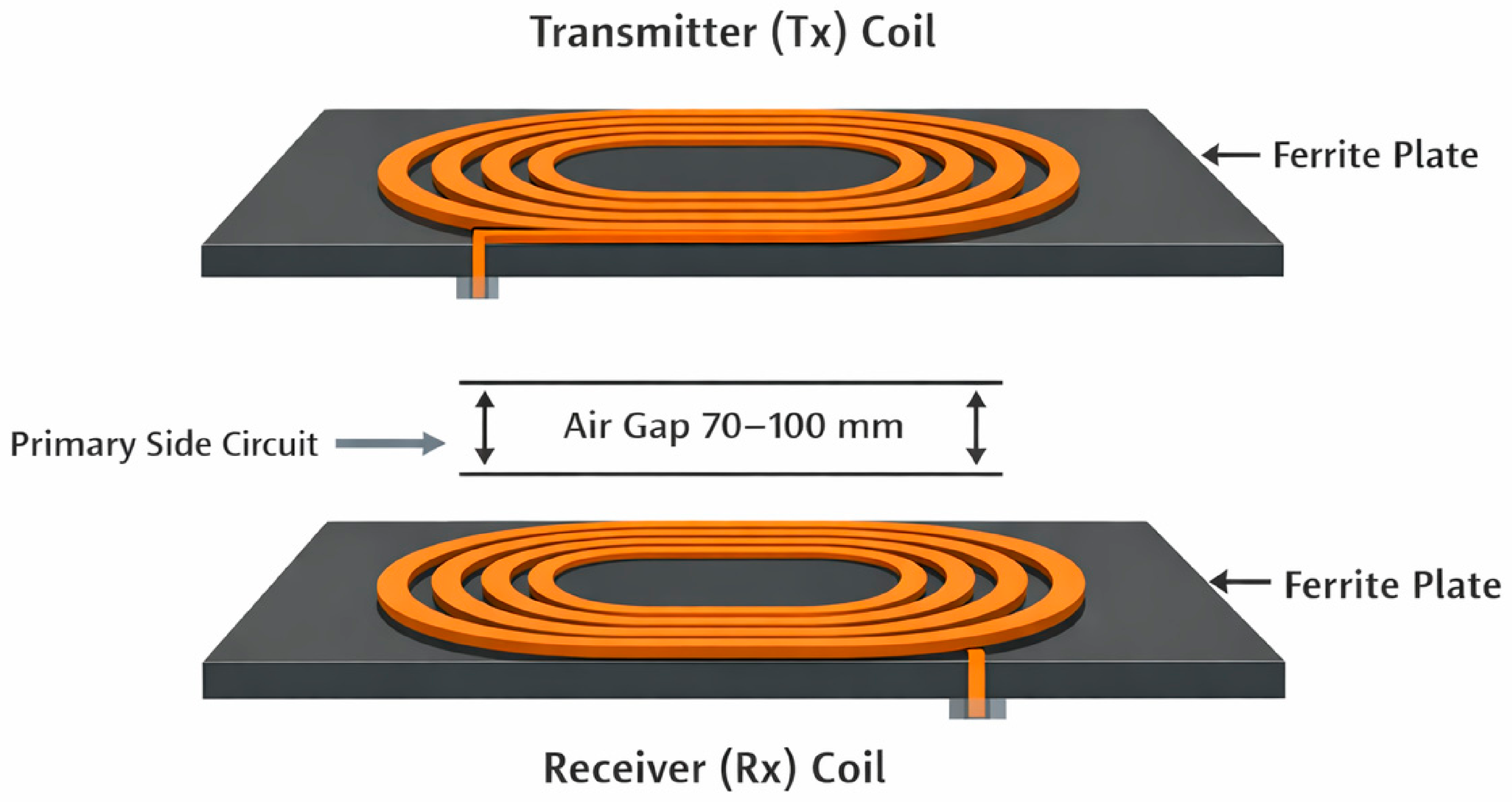
The transmitting and receiving coils form a loosely coupled inductive structure separated by an air gap. The alternating magnetic field generated by the transmitting coil induces voltage in the receiving coil (Rx pad) mounted on the vehicle. The efficiency of the power transfer process depends on several parameters, including the coil geometry, coupling coefficient, operating frequency, and the resonant compensation networks implemented on both sides of the system.
On the vehicle side, the induced high-frequency voltage is processed by the secondary compensation network and subsequently converted into DC power through a high-frequency rectifier stage. The resulting electrical energy is then delivered to the vehicle battery or to the EV DC bus. This architecture allows the charging system to operate without a direct conductive connection between the vehicle and the charging infrastructure.
The presented architecture is experimentally validated for static charging only. In static operation, the vehicle is positioned above the transmitting pad and remains stationary during energy transfer. Possible extension toward segmented or on-route charging scenarios remains outside the current validation scope and is considered only as future work.
3.2. Operating Principle of Inductive Power Transfer
Wireless transfer is achieved by generating an alternating magnetic field in the transmitting coil and inducing a voltage in the receiving coil through mutual inductance. Because EV charging operates with a relatively large gap and possible lateral misalignment, the system cannot rely on tight transformer coupling. Instead, efficient transfer is obtained by resonant operation, where the Tx/Rx inductances and compensation capacitors are tuned to the same operating frequency to reduce reactive power and increase useful transferred power.
3.3. Static Charging Mode
In static charging, the vehicle is parked above the ground-side transmitting pad and the relative position of the coils remains almost constant during energy transfer. This operating mode provides the most stable coupling conditions and is therefore used as the reference case for validating the magnetic coupler, the resonant compensation network, and the prototype-level power-transfer capability of the proposed system.
3.4. Perspective for Future On-Route Extension
The same inductive transfer principle may in principle be extended to segmented transmitting structures for future on-route charging applications. However, such operation introduces additional challenges related to time-varying coupling, changing alignment, power-transfer continuity, segment activation, and control adaptation. Since these aspects are not experimentally addressed in the present study, on-route operation is discussed here only as a future extension of the underlying static charging concept.
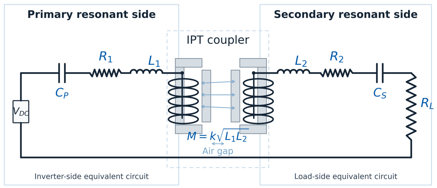
The same IPT principle underlies both static and future on-route charging concepts. In the present study,
Figure 2 illustrates the equivalent Tx/Rx representation used for the static charging platform, while on-route operation is discussed only conceptually. In static charging, energy transfer takes place between one fixed transmitting pad and one fixed receiving pad. In on-route charging, the same electromagnetic principle is preserved, but the ground-side transmitting structure is distributed into segmented pads that are energized according to vehicle position.
This transformer-based interpretation provides the basis for the electromagnetic modeling and optimization of the coupled coil system presented in the following sections.
3.5. Engineering Rationale of the Proposed Concept
The proposed coupler concept was developed and validated for static charging. The design is driven by a common set of engineering requirements, including adequate coupling across the air gap, compact pad dimensions, low coil losses, practical material use, and controlled stray-field exposure. These requirements define the basis of the design procedure presented in the next section. Possible extension of the concept toward segmented or on-route charging remains a topic for future investigation rather than a validated contribution of the present work.
4. Design Procedure and Formalized Parameter Selection
4.1. Engineering Requirements and Design Criteria
The development of the proposed WPT platform was treated as an engineering trade-off problem rather than as a purely single-objective optimization task. The main design criteria were (i) sufficient self-inductance of the transmitting and receiving pads; (ii) adequate magnetic coupling across the target air gap; (iii) low coil losses; (iv) acceptable pad dimensions, mass, and ferrite usage; and (v) controlled magnetic-field exposure in the occupied area. These criteria were considered jointly in order to obtain a practically realizable static EV charging platform.
4.2. Design Variables and Constraint Set
To formalize the parameter-selection process, the design vector can be written as
where
N is the number of turns, s is the turn spacing,
lcond is the effective conductor length,
nf is the number of ferrite plates,
mf is the ferrite mass,
C1 and
C2 are the primary and secondary compensation capacitances, and
f is the operating frequency. The final design is required to satisfy constraints related to inductance, coupling, transferred power, operating frequency range, overall package dimensions, and occupied-area magnetic-flux density.
In compact form, the constrained design problem may be expressed as
subject to
Here, η is the transfer efficiency, Ploss denotes the estimated coil and conduction losses, mtot is the total magnetic-pad mass, is the maximum magnetic flux density in the occupied area under the considered operating condition, and wη, wloss, wm, and wB are weighting factors reflecting the relative importance of the design objectives.
4.3. Iterative Parameter Selection Procedure
The final parameter set was selected by iterative constrained parameter sweep and simulation-supported refinement. The procedure started from the available geometric envelope of the equivalent IPT structure and then refined the number of turns, turn spacing, conductor arrangement, ferrite layout, and resonant compensation values. Candidate configurations were screened analytically with respect to inductance, coupling-dependent power-transfer capability, estimated losses, and geometric feasibility. The feasible candidates were then further refined using simulation-supported evaluation of magnetic behavior and field distribution.
This procedure does not seek a universal mathematical optimum in an abstract sense; instead, it identifies a practically balanced design that satisfies the imposed electrical, geometric, and safety-related constraints of the intended static charging application.
4.4. Design and Parameter-Selection Workflow
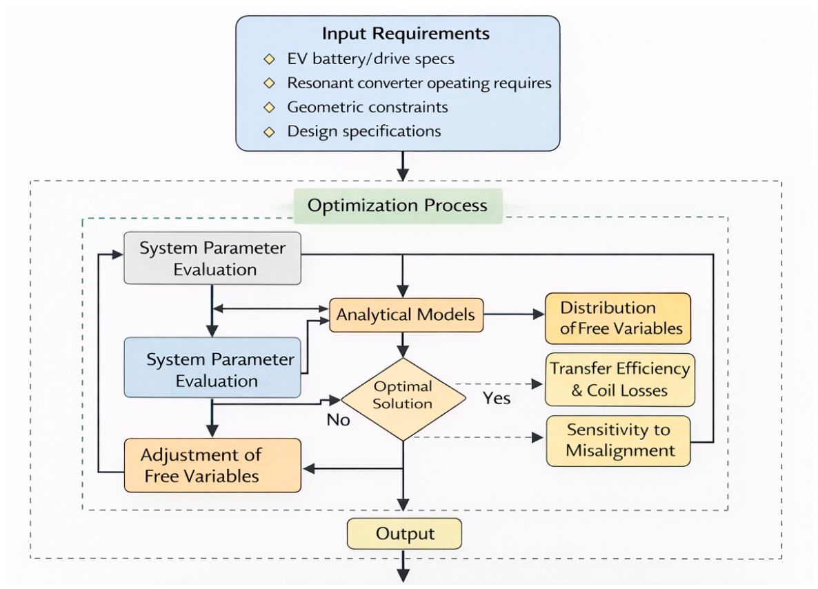
The workflow used for the design and validation of the proposed wireless charging platform is illustrated in
Figure 3. Rather than representing a black-box optimization routine, the workflow summarizes the sequence of engineering steps used to define, evaluate, refine, and finally validate the selected WPT platform.
As shown in
Figure 3, the process starts from the specification of the main application requirements, including EV-related operating conditions, target power level, geometric constraints, operating-frequency range, and occupied-area magnetic-field considerations. These inputs define the feasible design space of the system.
The workflow then proceeds through analytical IPT modeling and parameter screening, followed by simulation-supported refinement of the magnetic and electrical subsystems. At this stage, candidate configurations are evaluated with respect to inductance, coupling behavior, estimated losses, resonant compatibility, geometric feasibility, and occupied-area field control. If the obtained parameter set does not satisfy the imposed design criteria, the selected variables are adjusted and the evaluation sequence is repeated.
Once a feasible and practically balanced parameter set is identified, the resulting design is used as the basis for prototype-oriented implementation and experimental validation. Therefore,
Figure 3 should be interpreted as a formalized engineering design-and-selection workflow linking requirements, analytical modeling, refinement, and prototype verification for the proposed static EV WPT platform.
The formal mathematical relations used within this workflow are introduced in the Analytical Relations for the Compensated IPT System section, where the coupling-dependent power-transfer capability, reflected impedance, resonance conditions, and efficiency trends are derived explicitly.
6. Power Electronics and Compensation Network
6.1. Full-Bridge Topology and Resonant Operation
The power-electronic stage of the proposed wireless charging platform is based on a primary-side full-bridge inverter followed by a resonant compensation network and a coupled Tx/Rx magnetic structure. This arrangement provides the required high-frequency excitation of the transmitting coil and forms the electrical basis for inductive wireless power transfer.
On the primary side, the DC input source is conditioned by a DC-link stage, where the capacitor Cdc stabilizes the supply voltage. The full-bridge inverter converts the DC input into a high-frequency AC voltage in the range required for resonant inductive operation. This excitation is applied to the primary compensation network and the transmitting coil.
Because the transmitting and receiving coils are weakly coupled due to the relatively large air gap, efficient power transfer requires resonant operation. The compensation network is therefore designed to cancel the dominant inductive reactance of the coupled coils and to improve the transfer of active power across the air gap. In this way, the system operates close to resonance, reducing reactive power circulation and improving overall efficiency.
The transmitting and receiving coils form a loosely coupled inductive structure characterized by their self-inductances and mutual inductance. The alternating magnetic field generated by the transmitting coil induces a voltage in the receiving coil, thereby enabling contactless energy transfer between the ground-side and vehicle-side subsystems.
Equivalent resistive elements on the load side represent the aggregated losses and load behavior of the resonant circuit. These elements are included in the adopted circuit model in order to capture the practical operating conditions of the system.
The selected full-bridge topology ensures reliable high-frequency operation, efficient utilization of the DC source, and compatibility with the resonant compensation strategy. This configuration supports the experimentally validated static charging platform described in this paper. Possible extension toward segmented or on-route charging would require further investigation under time-varying coupling conditions and is therefore outside the present validation scope.
6.2. Secondary Interface and System-Level Topology Rationale
The compensation capacitors on the primary and secondary sides are selected to match the optimized inductance values of the realized coupler. In this way, the electrical design remains consistent with the magnetic design and maintains acceptable input impedance, resonant behavior, and power-transfer capability under practical EV charging conditions.
On the secondary side, the received high-frequency power is processed through the secondary resonant branch and converted into DC power by a high-frequency rectifier. The rectified output is then supplied to the battery or the vehicle DC bus. This arrangement allows the vehicle-side subsystem to receive useful electrical energy without a direct galvanic connection to the ground-side charging infrastructure.
The secondary-side interface must preserve resonant operation while providing a usable DC output for charging. In this respect, the adopted topology is justified by system-level rather than purely converter-level considerations. Its role is to excite the optimized coupler reliably, maintain resonant transfer, and support a practical EV charging platform that integrates magnetic performance, converter operation, and safety-oriented validation.
Static charging benefits from steady alignment and stable operating conditions, whereas future on-route charging extensions would require the same resonant principle to remain effective under changing coupling conditions and segmented infrastructure.
7. Prototype Development and Experimental Setup
7.1. Prototype-Oriented Development Approach
The proposed charging platform was validated through prototype realization rather than through simulation alone. The development sequence included optimized coil design, implementation of the primary full-bridge excitation stage, construction of a first prototype, extension to a second demonstrator installation, and magnetic-field measurements around the realized system. In this way, the study progressed from analytical and numerical optimization toward application-oriented hardware verification.
7.2. Prototype Realization and Test Conditions
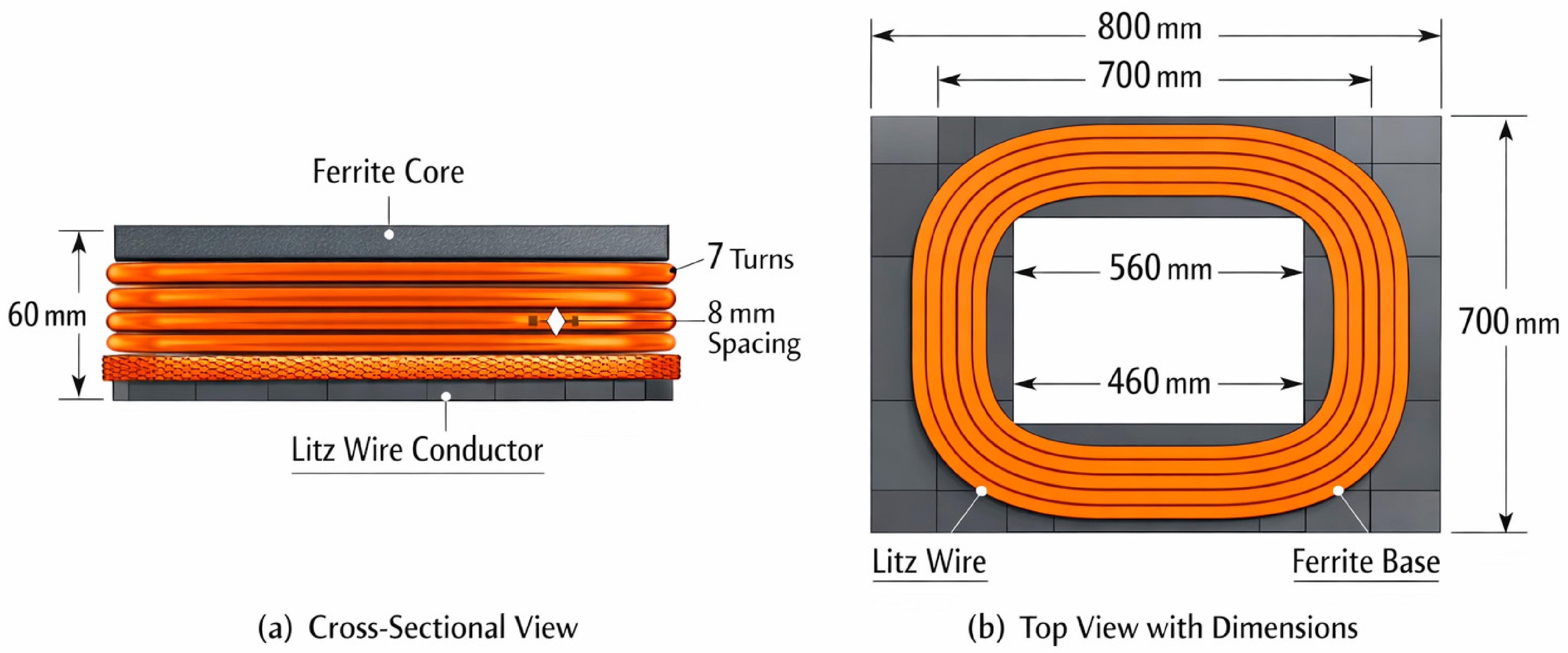
The optimized coupler was physically built using the final dimensions and material set reported in
Section 5. The realized hardware therefore represents the direct embodiment of the analytical and simulation-supported design procedure. The manufactured Tx/Rx magnetic structure preserved the optimized rectangular geometry and ferrite-assisted arrangement required for practical inductive power transfer across a non-negligible air gap. To further document the realized hardware platform, the main technical specifications of the developed IPT module and the corresponding prototype operating conditions are summarized in
Table 2.
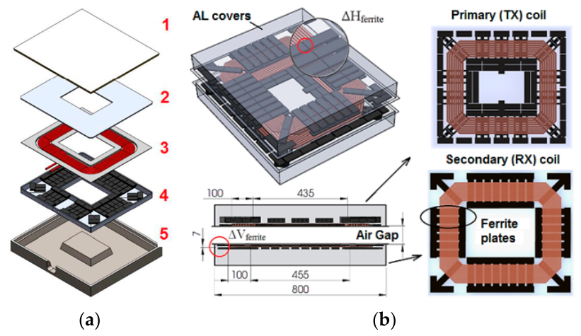
From the viewpoint of practical implementation, the transmitting pad was not treated merely as a laboratory magnetic assembly, but as a ground-side module intended for protected installation. Since the receiving coil is integrated into the electric vehicle, the transmitting coil requires mechanically robust and environmentally suitable housing. In the realized demonstrator, the ground-side module was implemented using a layered construction that included reinforced structural support, epoxy-resin encapsulation of the winding region, and ferrite-bar elements combined with shielding features. This packaging-oriented realization strengthens the practical relevance of the developed IPT platform beyond purely electromagnetic design considerations.
The first prototype was used to verify the compatibility of the optimized Tx/Rx coils, the equivalent IPT transformer, and the primary full-bridge inverter under controlled operating conditions. The available prototype data confirm operation at a nominal 30 kW charging level, with a peak capability of 45 kW for 1 min. At the rated 30 kW/5 Ω load condition, the realized system delivered 400 V DC and 75 A DC. Depending on load and coil alignment, the converter operated in the 12–20 kHz range using combined frequency-shift and phase-shift PWM control. Experimental validation was carried out for air gaps up to 100 mm, confirming the electrical compatibility between the optimized magnetic coupler and the implemented high-frequency full-bridge power stage.
A second prototype was developed as an installation and demonstration platform in order to move the work closer to practical deployment conditions and to support application-oriented validation of the concept. This demonstrator strengthens the engineering relevance of the study because it shows that the optimized coupler and converter concept can be transferred from prototype-level verification toward installation-oriented implementation.
In addition to the prototype-level validation, the realized platform was further documented from the viewpoint of practical implementation and representative converter-side operation. The corresponding mechanical realization of the transmitting module and the demonstrator installation are illustrated in
Figure 6.
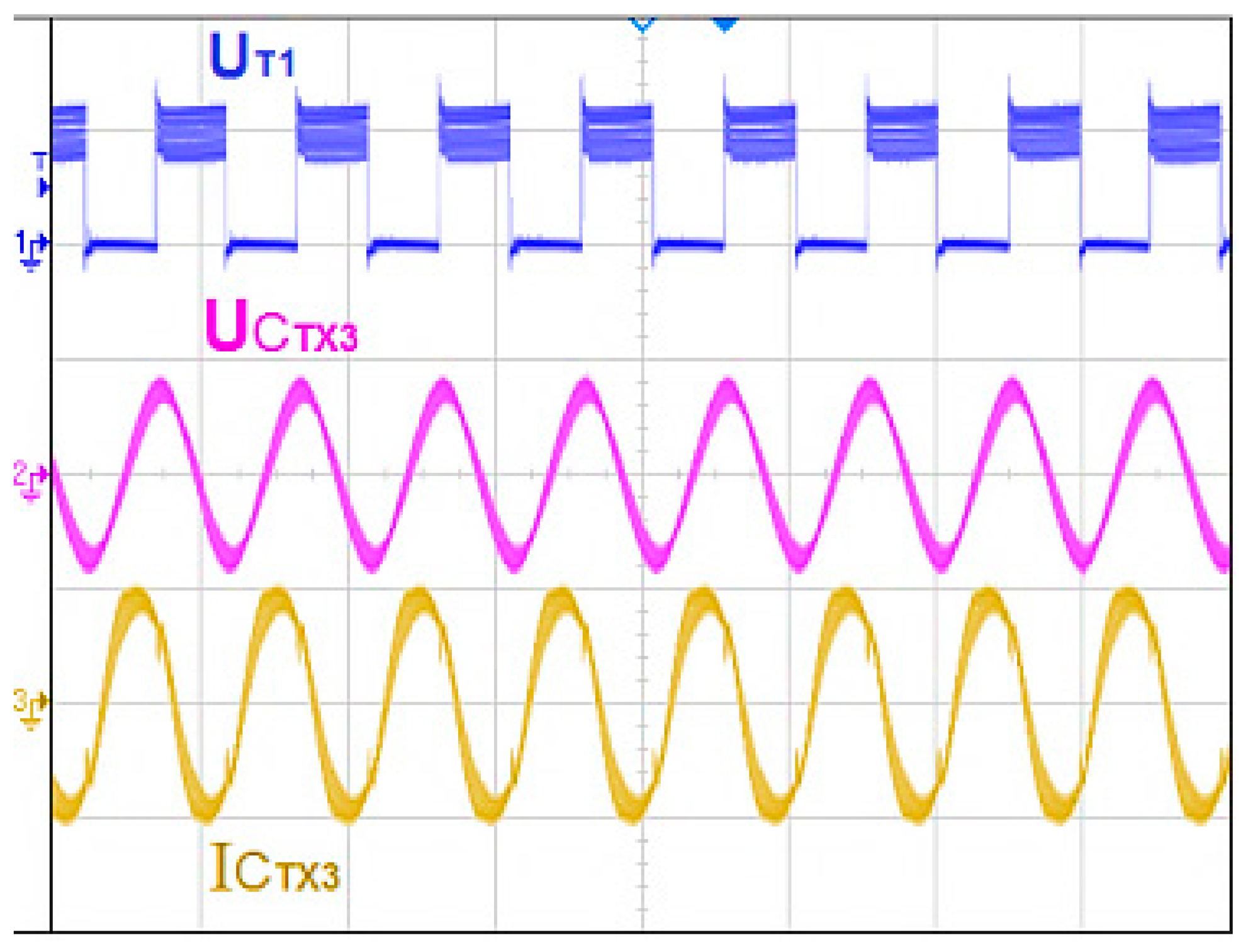
In addition to the documented mechanical realization, representative converter-side waveforms were recorded in order to verify the electrical behavior of the realized IPT module under practical operating conditions. These measurements illustrate the voltage and current behavior at the transmitting side of the resonant stage for a representative charging condition and defined coil displacement. The recorded waveforms provide direct experimental support for the electrical compatibility of the resonant power stage and the magnetic coupler beyond averaged efficiency measurements.
Representative measured waveforms obtained at the transmitting side of the IPT system are shown in
Figure 7.
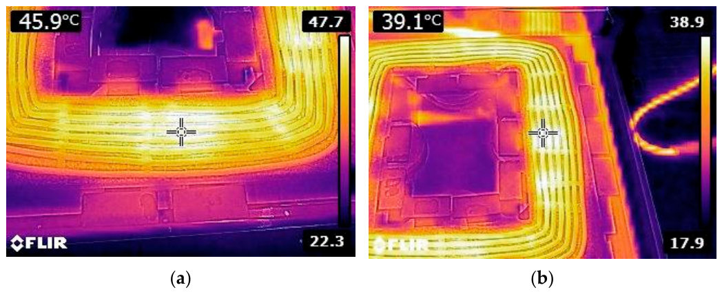
Thermographic images of the transmitting coil obtained using an infrared (FLIR) camera are presented in
Figure 8. The images illustrate the temperature distribution along the winding during operation and provide indirect experimental evidence of current distribution and loss localization in the coil structure. The thermographic patterns qualitatively indicate a non-critical temperature distribution under the reported operating conditions and provide additional experimental support for the practical operation of the realized transmitting pad.
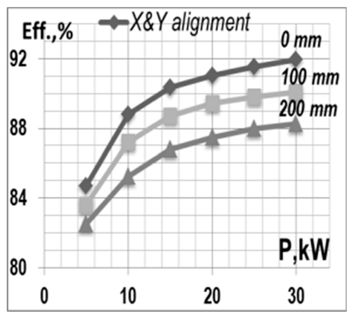
The experimentally reported operating data indicate an efficiency range of 80–92%, with the most favorable values obtained around 30 kW and a vertical air gap of approximately 70 mm. Appropriate transfer efficiency was maintained for air gaps in the range of about 70–100 mm. The corresponding efficiency map also illustrates the sensitivity of the realized IPT module to horizontal coil displacement under the investigated X- and Y-direction misalignment conditions, confirming that useful transfer performance was maintained for the reported experimental cases.
Figure 9 presents the experimentally measured efficiency as a function of output power for different X- and Y-direction coil misalignments and supports the practical operating range reported for the realized prototype.
In addition to transfer-efficiency validation, representative occupied-area magnetic-field measurements were performed around the demonstrator installation in order to assess the practical field-exposure behavior of the realized platform.
7.3. Demonstrator Installation and Measurement Basis
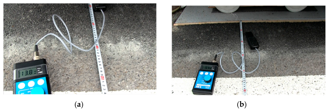
In addition to transfer-oriented validation, the experimental campaign included representative measurements of magnetic flux density in the accessible area around the charging coils. Representative magnetic-flux-density measurements performed around the demonstrator installation are shown in
Figure 10.
The purpose of these tests was to assess representative magnetic-field levels in the occupied area around the demonstrator and to support safety-oriented validation of the proposed design. The reported values correspond to representative spot measurements obtained under the stated operating conditions and should be interpreted as indicative measurements rather than as a complete spatial field map. For frequencies up to 150 kHz, the adopted reference safety level was B = 27 μT.
The developed hardware platform supports the experimental validation of the proposed static charging concept. In the present work, the prototypes verify the operation of the coupler and converter under fixed-position charging conditions. Any extension toward segmented or on-route charging should be regarded as future work rather than as part of the current validation scope.
The validation campaign progressed through three stages: first, verification of the electrical compatibility and basic WPT functionality of the initial prototype; second, demonstrator-level installation of the developed platform; and third, representative occupied-area magnetic-field measurements for safety-oriented assessment.
8. Results and Discussion
8.1. Magnetic and Electrical Performance
The optimized coupler achieved an inductance of 60 μH, a coupling factor of 0.45, and coil losses of approximately 2%, confirming that the proposed design route yields a physically realizable high-power EV charging coupler. The prototype platform was experimentally validated at a nominal 30 kW operating level, with a peak capability of 45 kW for 1 min. The measured efficiency was in the range 80–92%, with the most favorable operation observed around 30 kW and a vertical air gap of approximately 70 mm. Appropriate transfer efficiency was maintained for vertical air gaps in the range 70–100 mm, while the reported tests also confirmed the expected sensitivity of transfer efficiency to horizontal coil misalignment under the investigated displacement conditions. In addition, representative occupied-area magnetic-flux-density measurements remained below the adopted reference threshold of 27 μT for frequencies up to 150 kHz.
The analytical relations developed in Section Analytical Relations for the Compensated IPT System support the interpretation of the reported experimental trends. In particular, the transferred power and the near-resonant efficiency depend strongly on the coupling-dependent term . Consequently, the experimentally favorable operating region observed around 30 kW and a vertical air gap of approximately 70 mm can be interpreted as a practical compromise between sufficiently strong coupling, acceptable current levels, and effective resonant tuning. Conversely, when the vertical gap increases or lateral misalignment becomes more pronounced, the coupling factor decreases, the reflected impedance changes, and the useful transferred power and efficiency are correspondingly reduced. This analytical interpretation is consistent with the measured efficiency range of 80–92% and with the experimentally observed sensitivity to coil displacement.
The achieved coupling factor is favorable for a practical EV charger with a non-negligible air gap. At the same time, the low reported coil losses indicate that the improvement in coupling was not obtained at the expense of excessive internal dissipation. The design therefore performs as a balanced engineering compromise.
The realization of a first prototype and a second demonstrator confirms that the proposed concept progresses beyond analysis and optimization to application-oriented hardware validation. This substantially strengthens the contribution of the work.
The measured magnetic induction in the occupied area remained below the adopted threshold of 27 μT for frequencies up to 150 kHz. This is a key practical result because it demonstrates that the optimized charger combines transfer-oriented design with controlled field exposure.
The final realized platform should be interpreted as a constrained engineering trade-off solution rather than as a universally optimal design in a purely mathematical sense. Its practical value lies in the simultaneous achievement of adequate coupling, acceptable winding losses, feasible dimensions, manageable mass, and controlled occupied-area magnetic-field levels under the reported static charging conditions.
8.2. Limitations and Strength of the Experimental Results
The reported results should be interpreted as prototype-level validation of the proposed design methodology rather than as a complete deployment-ready characterization. The strongest experimentally supported findings concern the realized magnetic coupler, the nominal 30 kW static prototype validation, and the representative occupied-area magnetic-field assessment. In this sense, the manuscript presents a coherent combination of design, realization, and measurement-based verification that supports the practical relevance of the proposed WPT platform. Future work should extend the efficiency mapping under vertical and horizontal misalignment, provide broader spatial field characterization, and investigate segmented dynamic charging operations.
9. Electromagnetic Safety Assessment
9.1. Assessment Basis and Measurement Context
Electromagnetic safety assessment is essential for any inductive EV charger because the transfer process relies on alternating magnetic fields in an area that may be accessible to users or bystanders. For this reason, field exposure is treated here as part of the design validation rather than as a secondary issue.
Representative magnetic-flux-density measurements around the demonstrator installation yielded 13.8 μT at 125 mm from the coil and 5.4 μT at 225 mm, both below the adopted reference threshold of 27 μT for frequencies up to 150 kHz. These results support the practical suitability of the realized coupler for occupied-area operation under the reported experimental conditions, while remaining limited to representative measurement points rather than a full spatial exposure map.
The measured magnetic field in the occupied area is shaped by the geometry of the Tx/Rx pads, the coupling condition, the ferrite layout, and the operating frequency. In the present system, these factors are governed by the optimized 700 × 800 × 60 mm coupler and the ferrite-assisted magnetic design. Representative magnetic-flux-density measurements around the demonstrator installation are shown in
Figure 10.
9.2. Experimental Safety Result and Implications
The favorable safety result is consistent with the ferrite-assisted coupler design and the selected electrical operating conditions of the realized static charging platform. For static charging, the result supports the suitability of the charger for user-accessible installations.
9.3. Scope and Limitations of the Safety Evaluation
The present manuscript supports the safety conclusion at the level of the adopted threshold, the frequency range, and the occupied-area compliance result. It does not claim a full spatial field map or a complete point-by-point exposure matrix, because those numerical details are not available in the current source material.
Overall, the safety assessment confirms that the optimized WPT platform satisfies an essential practical requirement for EV charging applications and strengthens the application-oriented value of the proposed methodology. To support the safety-oriented interpretation of the experimental results, the representative occupied-area magnetic-flux-density measurements are summarized in
Table 3 together with the corresponding distances from the transmitting module and the adopted reference threshold.
10. Conclusions
This work presented the design and prototype-level validation of an inductive wireless power transfer platform for static EV charging. The realized coupler achieved an inductance of about 60 μH, a coupling factor of about 0.45, and estimated coil losses of approximately 2%, while the developed prototype was validated at a nominal 30 kW operating level for air gaps up to about 100 mm. The measured transfer efficiency was in the range 80–92%, with favorable operation observed around 30 kW and a vertical air gap of approximately 70 mm. Representative occupied-area magnetic-flux-density measurements remained below the adopted 27 μT reference level under the reported operating conditions, supporting the practical suitability of the realized system for static charging applications.
The present study experimentally validates the platform under static charging conditions only. Possible extension toward segmented or on-route charging remains outside the current validation scope and is reserved for future work. Future research should include broader efficiency mapping under vertical and horizontal misalignment, extended spatial magnetic-field characterization, and experimental investigation of dynamic or quasi-dynamic charging operation.