1. Introduction
The increasing integration of renewable energy sources into modern power systems has created a growing demand for advanced control strategies capable of ensuring high operational performance and superior power quality (PQ). Among renewable technologies, wind energy (WE) has emerged as one of the most mature and economically competitive solutions for large-scale electricity generation [
1]. Wind turbines are used to harness wind power. Turbines play a pivotal role in modern electricity generation, converting the kinetic energy of natural resources (WE) into usable energy [
2]. Turbines can also be used in hydroelectric power plants, where the energy of flowing water is converted to drive generators and thus produce electricity [
3]. These technologies are essential in mitigating global warming because they generate electricity without burning fossil fuels, thus reducing greenhouse gas emissions [
4]. By replacing coal- and gas-fired power plants with renewable energy systems, wind turbines contribute to lowering the carbon footprint and slowing climate change. They also promote sustainability by relying on inexhaustible resources like wind and water, ensuring long-term energy security [
5]. On land, the main types include onshore wind turbines and hydroelectric turbines on dams and rivers. At sea, large-scale wind turbines are installed in the oceans, where stronger and more stable winds allow for greater power generation, making them a key component of future clean energy systems [
6]. Wind turbines have recently seen significant developments, with the emergence of new technologies that are more robust and perform better than traditional turbines. Multi-rotor wind turbines (MRWTs) are among the most prominent modern technologies that have recently emerged to replace traditional turbines in the renewable energy sector [
7]. This technology is characterized by high performance and robustness, making it a promising and reliable solution. It has been the subject of numerous research studies [
8,
9]. MRWTs equipped with a 1.5 MW doublyfed induction generator (DFIG) have gained widespread adoption due to their cost-effectiveness, flexible variable-speed operation, and reduced requirements for the power converter rating [
10].
Despite these advantages, DFIG-based wind energy conversion systems (WECSs) remain sensitive to grid disturbances, parameter uncertainties, and nonlinear operating conditions [
11]. These challenges often manifest as active and reactive power (
Ps and
Qs) oscillations, current ripples, and steady-state errors (SSEs), which adversely affect PQ and overall system reliability [
12]. Consequently, advanced control methodologies have become a central focus of recent research efforts [
13]. The work [
14] proposes an enhanced control strategy for a DFIG-based WE system by optimally tuning proportional-integral (PI) controllers using a novel multi-objective formulation combined with metaheuristic algorithms such as Grey Wolf Optimizer and Whale Optimization Algorithm (WAO). The main contribution lies in improving the dynamic and steady-state performance of both rotor-side and grid-side converters (RSC and GSC) over a wide range of operating conditions. Simulation results on a 6 MW wind farm model demonstrate better compliance with grid codes during disturbances, improved stability, and enhanced overall system performance compared to conventional PI tuning approaches. However, the study has several limitations: it relies entirely on simulation without experimental validation, which weakens the practical applicability of the results; the proposed optimization approach may introduce higher computational complexity compared to traditional methods; and the comparison is limited mainly to conventional PI-based formulations rather than a broader set of advanced nonlinear or intelligent control strategies. Additionally, uncertainties such as real grid disturbances, parameter variations, and hardware constraints are not deeply explored, leaving questions about robustness in real-world deployments. The study [
15] proposes a WOA-based tuning of PI controllers for a DFIG wind power system incorporating a modular multilevel converter (MMC) on the grid side, aiming to enhance PQ and dynamic performance. The main contribution lies in combining metaheuristic optimization with advanced converter topology, where WOA is used to optimally adjust controller gains, leading to improved regulation of DC-link voltage,
Ps/
Qs, and overall system stability under varying operating conditions. Consistent with similar WOA-based control approaches, such optimization techniques are known to provide faster convergence, better global search capability, and improved transient response compared to conventional tuning methods. The reported results—primarily obtained through MATLAB 2014/Simulink simulations—indicate reduced oscillations, enhanced tracking performance, and better harmonic behavior, particularly due to the use of MMCs, which are recognized for superior harmonic performance and scalability in grid-connected systems. However, the work has notable shortcomings: it lacks experimental or hardware-in-a-loop validation, limiting confidence in real-world applicability; the computational burden and implementation complexity of combining WOA with MMC control are not thoroughly analyzed; and comparisons are restricted mainly to the traditional PI approach rather than more advanced nonlinear or predictive control strategies. Additionally, the study provides limited discussion on robustness under severe grid faults, parameter uncertainties, or communication delays, which are critical factors for practical deployment of DFIG-based WE systems.
Among conventional strategies, direct power control (DPC) has been widely applied in DFIG systems due to its fast dynamic response and relatively simple structure [
16]. However, DPC suffers from inherent limitations, including high power and current ripples, variable switching frequency, and sensitivity to parameter variations [
17]. These drawbacks necessitate the development of alternative control approaches capable of enhancing dynamic behavior while maintaining robustness and efficiency.
1.1. Literature Review
Numerous studies have investigated performance enhancement techniques for DFIG-based wind turbines. Classical PI controllers remain the most commonly implemented solution in industrial applications due to their simplicity and ease of deployment [
18,
19]. However, PI regulators are fundamentally designed for linear systems and may exhibit degraded performance under nonlinear dynamics, parameter uncertainties, and variable wind conditions [
20,
21].
To overcome these limitations, several advanced control techniques have been proposed, including sliding mode control (SMC) [
22], model predictive control (MPC) [
23], and adaptive control approaches [
24,
25,
26]. SMC offers strong robustness against parameter variations but introduces chattering effects that increase current ripple and mechanical stress [
27]. MPC provides excellent dynamic performance; however, it requires high computational resources and accurate system models, limiting its practical implementation in medium-scale wind systems [
28]. The paper [
29] introduces an artificial neural network (ANN)-based DPC strategy for DFIG-based WE systems, aiming to overcome the well-known limitations of classical DPC, such as power ripples and poor harmonic performance. The main contribution lies in the development of a dual multilayer perceptron (MLP) ANN controller for direct regulation of
Ps and
Qs, which significantly improves PQ and dynamic response. The results show notable performance gains, including a substantial reduction in stator current total harmonic distortion (THD) (down to about 1.29% compared to 2.76% for DPC-PI), mitigation of current ripples, and operation at near-unity power factors. Moreover, unlike many similar studies, the approach is validated not only through MATLAB/Simulink simulations but also via real-time implementation using an OPAL-RT simulator, strengthening its practical relevance and demonstrating feasibility for real-world applications. However, despite these strengths, the work has some limitations: the ANN design and training process is not deeply analyzed in terms of computational cost, convergence, or scalability; the study focuses mainly on specific operating conditions (e.g., step wind profile), with limited exploration of robustness under severe grid faults or highly stochastic wind variations; and comparisons are restricted to conventional DPC variants rather than more advanced control methods such as model predictive or adaptive nonlinear control. Additionally, implementation challenges such as hardware complexity and real-time deployment constraints are not fully discussed, leaving open questions about large-scale industrial applicability. The study [
30] proposes a second-order sliding mode control (SOSMC) strategy to enhance the DPC method of DFIG-based wind turbines. The approach significantly reduces power ripples, improves robustness against parameter variations, and enhances dynamic response compared to the classical DPC method. However, the method introduces higher control complexity and potential implementation challenges, while results are limited to simulations, with no experimental validation to confirm real-world applicability.
The study [
31] proposes a voltage-modulated DPC strategy for DFIG systems based on extended power theory to address unbalanced grid voltage conditions. The method effectively reduces power oscillations, improves current quality, and enhances system stability under grid faults. However, the approach increases control complexity and relies mainly on simulation results, with limited experimental validation and insufficient analysis of robustness under highly variable operating conditions. The authors in [
32] propose an advanced control scheme combining the DPC method, type-2 fuzzy logic, and the flower pollination algorithm optimization to enhance DC-link voltage regulation in autonomous squirrel cage generator-based wind systems, while accounting for iron losses. The results demonstrate improved voltage stability, reduced oscillations, and better dynamic performance. However, the approach is relatively complex, with high computational requirements, and validation is limited to simulations, leaving uncertainties regarding real-time implementation and robustness under varying operating conditions.
DPC, inspired by the principles of direct torque control, has attracted significant attention in DFIG applications [
33,
34]. By directly regulating
Ps and
Qs, DPC eliminates the need for inner current control loops and ensures rapid dynamic response [
35,
36]. Nevertheless, conventional DPC schemes typically generate considerable power and current ripples due to hysteresis-based switching and variable switching frequency [
37,
38]. Although improvements such as space vector modulation (SVM)-based DPC [
39] and predictive DPC [
40] have been proposed, ripple mitigation remains a persistent challenge.
In parallel, fractional-order control has emerged as a promising alternative to classical integer-order controllers [
41]. Fractional-order PI (FO-PI) controllers introduce additional degrees of freedom through non-integer integration orders, enabling enhanced flexibility in tuning and improved robustness [
42]. The extra fractional parameter allows better trade-offs among transient response, stability margins, and disturbance rejection capabilities [
43]. Applications in power electronics and renewable energy systems have demonstrated improved damping characteristics and enhanced steady-state accuracy compared to conventional PI regulators [
44].
Furthermore, cascaded control structures are widely implemented in DFIG systems to decouple
Ps and
Qs regulation while improving dynamic performance [
45]. By combining outer power loops with inner current control loops, cascaded architectures provide enhanced stability and disturbance rejection [
46]. However, optimal tuning of such structures—especially when fractional-order regulators are involved—remains a significant challenge.
To address tuning complexity, intelligent optimization algorithms such as genetic algorithms (GAs) [
47], particle swarm optimization [
48], and artificial neural networks [
49] have been employed. GAs, inspired by evolutionary principles, are particularly suitable for multi-objective optimization problems involving nonlinear and complex systems [
50]. GA-based tuning has demonstrated promising results in optimizing controller gains while minimizing performance indices such as integral error, ripple magnitude, and settling time [
51]. The GA-based strategy is considered one of the most prominent strategies that can be relied upon to improve the operational performance and robustness of control strategies [
52]. This strategy is easy and simple to use, as it can be implemented using MATLAB with the GA tool. This strategy has been applied in several research papers [
53,
54,
55,
56]. Due to its high ability to improve performance, efficiency, robustness, dynamic response, and ease of implementation, it has been adopted in this paper.
Despite these advancements, limited research has investigated the integration of cascaded fractional-order PI control with intelligent optimization for medium-rated (1.5 MW) DFIG-based MRWT systems, particularly with a comprehensive comparison against DPC in terms of ripple reduction, SSE improvement, and durability performance.
1.2. Research Gaps and Objectives
Although substantial progress has been achieved in DFIG control strategies, several research gaps remain:
Limited integration of fractional-order control in cascaded DFIG architecture: The application of cascaded fractional-order PI regulators within DFIG control structures for MRWT systems remains insufficiently explored.
Incomplete ripple mitigation in DPC-based approaches: Existing DPC improvements reduce ripple to some extent; however, significant Ps/Qs and current oscillations persist, affecting grid PQ and mechanical durability.
Lack of intelligent multi-objective optimization: Conventional tuning methods based on trial-and-error or linearizations do not guarantee optimal performance under variable operating conditions.
Limited durability-focused evaluation: Many studies emphasize transient performance while overlooking long-term durability factors such as Qs ripple and current stress, which directly influence component lifespan.
To address these gaps, this study proposes a GA-optimized cascaded fractional-order PI control strategy for a 1.5 MW DFIG-based MRWT system. The objective is to systematically minimize Ps ripple, Qs ripple, current ripple, and SSE while ensuring robust dynamic performance and enhanced PQ.
1.3. Motivation and Contributions
The integration of DFIG-based MRWTs into the electrical grid requires precise control strategies to ensure high PQ and accurate tracking of Ps and Qs references. The conventional DPC method with PI regulators (DPC-PI) can be limited in reducing power and current ripples, particularly under varying operating conditions. To address these challenges, this study proposes a cascaded fractional-order PI (CFO-PI) controller optimized via a GA. The proposed strategy aims to improve dynamic performance and PQ, as demonstrated through simulation-based comparative analysis. The study focuses on measurable performance indicators such as Ps and Qs ripples, current THD, and SSEs, without extrapolating to durability, thermal stress reduction, or system lifespan.
The main contributions of this paper are summarized as follows:
Development of a GA-optimized cascaded fractional-order PI technique tailored for a 1.5 MW DFIG-based MRWT system.
Comprehensive comparison with the conventional DPC-PI approach.
Reduction in Ps ripple by 61.71% compared to DPC-PI.
Reduction in Ps SSE by 72.60%, demonstrating improved tracking accuracy.
Enhancement of durability performance, including a 52.03% reduction in Qs ripple and a 56% reduction in current ripple.
Improved robustness and dynamic response under varying operating conditions due to the flexibility of fractional-order control.
These contributions demonstrate that integrating fractional-order control with intelligent genetic optimization provides a highly effective alternative to traditional DPC-PI strategies.
As shown in
Table 1, existing fractional-order PI controllers are typically limited by manual tuning and focus primarily on basic dynamic performance, while GA-tuned or modified controllers generally optimize a single performance metric, such as overshoot or ripple, without addressing multiple objectives simultaneously. In contrast, the proposed GA-optimized CFO-PI integrates a cascaded fractional-order structure with multi-objective GA optimization, enabling simultaneous reduction in
Ps and
Qs ripples, SSE, and current fluctuations. This holistic approach not only enhances PQ and tracking accuracy but also improves system robustness, demonstrating a clear advancement over prior fractional-order and GA-based control schemes for DFIG-based MRWTs.
1.4. Paper Organization
The remainder of this paper is organized as follows:
Section 2 presents the theoretical foundation of the FO-PI controller, including stability analysis based on Lyapunov theory and comparison with other controllers.
Section 3 describes the proposed cascaded power control methodology.
Section 4 details the MATLAB implementation and performance evaluation under various test scenarios.
Section 5 concludes the paper and outlines future research directions.
2. FO-PI Controller
The FO-PI regulator is a type of controller that is similar to the classical PI regulator, but with an added “fractional” order. This means that the integral term is now a fractional order, which allows for more complex calculations and responses [
57]. Instead of the conventional transfer function
, the FO-PI controller is expressed as [
58]
where α is the fractional integration order, which allows tuning between a pure PI (α = 1) and a fractional-order integrator (0 < α < 1), s is the Laplace variable, and
kp and
ki are the controller gains.
Generally, the value of α is related to the system under study; its value can be greater than 1, or it can be negative. The value of α relates to the system’s operational performance. The more optimal the α value, the more satisfactory the system’s operational performance, resulting in high power/current quality. Therefore, it is essential to choose a suitable value for α. Using artificial intelligence strategies, such as genetic algorithms, allows for the optimal selection of α values, thereby improving the operational performance and robustness of the designed approach.
This additional parameter introduces an extra degree of freedom, enabling more flexible shaping of the system’s frequency response and phase margin. The fundamental principle of the FO-PI regulator is based on fractional calculus, which incorporates a “memory effect” by accounting for past system states in a weighted manner rather than relying solely on instantaneous error accumulation [
59]. This characteristic enhances disturbance rejection capability and improves steady-state accuracy. Among its primary advantages are superior robustness against parameter variations, improved damping characteristics, reduced SSE, and enhanced ripple attenuation in power electronic and renewable energy systems [
60].
The FO-PI regulator depicted in the equation deviates from those documented in the extant literature with respect to form factor, gain, robustness, complexity, and ease of configuration and implementation. The approach delineated in Equation (1) is subject to modification in accordance with the value of alpha (α).
The fractional-order PI controller is defined in the Laplace domain as:
where H(s) is the controller transfer function in the Laplace domain.
Fractional exponent notation: is standard and unambiguous in the control literature. Avoid ambiguous parentheses like , which could be misinterpreted as the entire sum raised to α.
If α = 1, the FO-PI reduces to the classical PI controller: H(s) = kp + ki/s.
If α < 1, the integral action exhibits a memory effect and a frequency-dependent gain, improving low-frequency performance.
Timedomain representation: The FO-PI control law in the time domain can be expressed using the Caputo fractional derivative:
where
denotes the fractional integral of order α of the error signal
e(
t).
The condition applied to the FO-PI controller represented in Equation (1) is that the value of alpha (α) must not be 0 to ensure its validity.
The controller represented in Equation (1) is an FO-PI regulator when alpha is neither 0 nor 1.
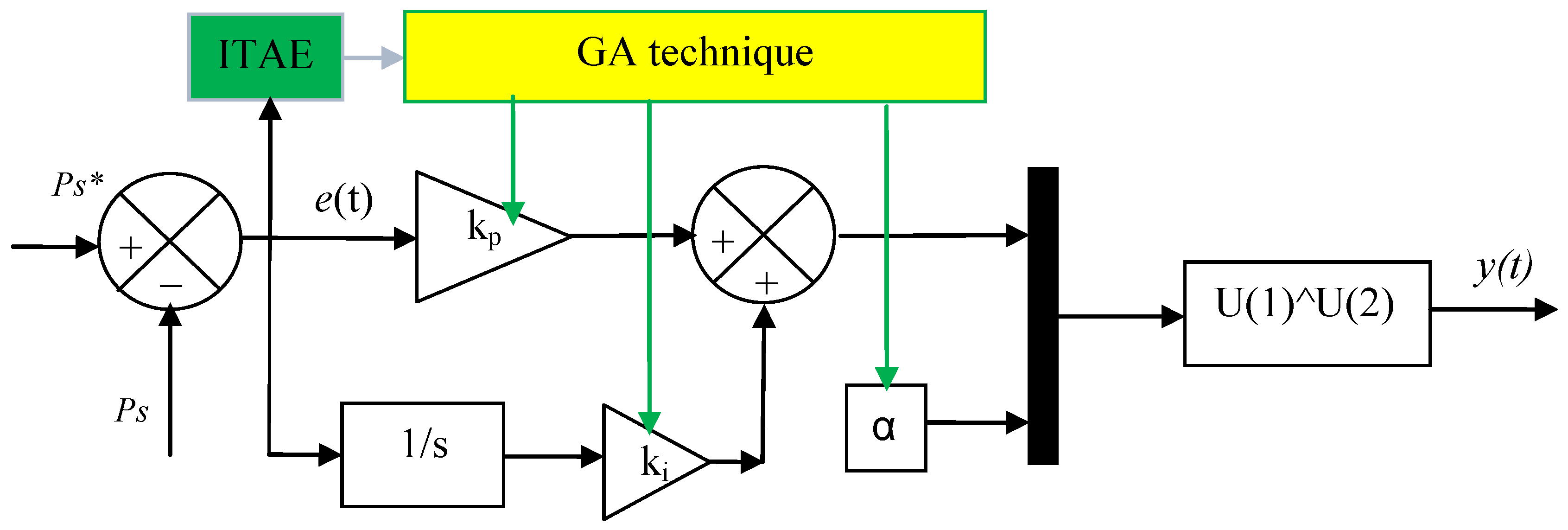
Figure 1 represents the controller designed in this paper. Gain values are determined using a GA. The optimal gain is calculated using the integral of time-weighted absolute error (ITAE). The characteristics of the GA strategy employed to ascertain optimal win values are enumerated in the
Supplementary File. The objective function for the GA-based optimization was chosen as the Integral of ITAE because it effectively penalizes errors that persist over longer durations, thereby improving both transient and steady-state performance. Unlike simple error metrics, ITAE places greater emphasis on long-lasting deviations, ensuring faster error decay and smoother tracking of reference signals. This characteristic is particularly beneficial for multi-rotor DFIG systems, where minimizing sustained deviations in
Ps and
Qs is critical for PQ and system stability. By using ITAE (Equation (4)), the optimization promotes controllers that achieve not only small error magnitudes but also rapid settling, making it a suitable and robust choice for the multi-objective control objectives of the proposed CFO-PI strategy.
The parameters used for the implementation of the GA in this study are summarized in
Table S1 (Supplementary File). The optimization problem involves four decision variables corresponding to the controller parameters, each bound within the range [0, 1000]. The GA employs a population of 20 individuals represented as double vectors and evolves them through a maximum of 100 generations. The initial population is generated using the default constraint-dependent creation function. Parent selection is performed using the stochastic uniform selection method, while the fitness values are scaled using a rank-based scaling function to preserve diversity and avoid premature convergence. A scattered crossover operator is applied with a crossover fraction of 0.8, and elitism is ensured by preserving the best two individuals in each generation. Mutation is implemented using the default constraint-dependent mutation function to maintain feasible solutions within the defined bounds. The algorithm also includes a forward migration strategy with a migration fraction of 0.2 and an interval of 20 generations to enhance exploration of the search space. The optimization process uses a serial evaluation of the fitness function and penalty-based constraint handling with an initial penalty value of 10 and a penalty factor of 100. Convergence is controlled through several stopping criteria, including a function tolerance of 10
−6, a nonlinear constraint tolerance of 10
−6, and a stall generation limit of 50 generations. These settings ensure a balanced trade-off between exploration and exploitation, enabling efficient identification of optimal controller parameters.
However, the FO-PI regulator also presents certain drawbacks, including increased computational complexity, more challenging parameter tuning procedures, and the requirement for approximation techniques to implement fractional operators in digital control platforms. Despite these challenges, the enhanced flexibility and improved performance offered by fractional-order control make it a promising solution for advanced control applications in modern renewable energy systems.
The stability analysis of the fractional-order PI regulator is conducted based on Equation (1) and is examined using Lyapunov stability theory.
To demonstrate the stability of the proposed system, the following fundamental steps are considered:
The control strategy developed in this work is primarily based on the classical PI control structure, as expressed in Equation (5).
In the case of a fractional order with exponent α, the controller can be interpreted using fractional calculus (Cabuto’s definition). The equivalent expression in the time domain becomes:
The operator D−α is defined as the fractional integral operator ().
The operator introduces a memory effect.
For a fractional-order system of order α:
According to fractional Lyapunov theory, the equilibrium point is asymptotically stable if:
Additionally, for linear fractional systems
It is imperative to note that the system at hand is asymptotically stable if and only if
This is the fractional stability condition.
Substituting these values into the closed-loop transfer function yields the following result:
The characteristic equation is
This represents a fractional-order characteristic equation.
Choose a quadratic Lyapunov function:
Its fractional derivative (Caputo sense) is
Substituting the system dynamics:
Thus, matrix A must be negative definite.
And the closed-loopholes must satisfy:
The regulator is Lyapunov asymptotically stable if
All closed-loop poles satisfy:
For the classical case (α = 1), the FO-PI controller reduces to a conventional PI regulator. Stability is ensured when all closed-loop poles lie in the left half of the complex plane, consistent with standard linear control theory.
When 0 < α < 1, the stability region in the complex plane becomes a sector, which enlarges the set of eigenvalues that can result in stable closed-loop behavior. This sectoral region provides additional flexibility in tuning the controller and can influence the damping characteristics and dynamic response of the system. However, it does not guarantee global stability under all operating conditions or parameter variations.
Using Lyapunov fractional stability theory, the FO-PI controller can be considered asymptotically stable under the following conditions:
The controller gains kp, and ki are positive.
The closed-loop eigenvalues remain outside the instability sector defined by the fractional-order dynamics (Equation (23)).
Within these constraints, the fractional-order parameter α affects the local stability margin and the response characteristics of the regulator. While smaller values of α can provide smoother control action and influence low-frequency performance, they do not inherently extend global robustness beyond what is supported by the eigenvalue placement.
Fractional-order PI regulators differ from classical PI, PID, or other feedback controllers primarily in their flexible frequency-domain shaping and the additional tuning parameter α. Comparative analyses of performance, including damping, ripple attenuation, and transient response, should be interpreted based on simulation results or locally verified stability conditions rather than as general, unconditional improvements.
In summary, the stability analysis demonstrates that the proposed FO-PI controller can maintain local asymptotic stability for positive controller gains and properly placed eigenvalues, providing predictable and controllable dynamic behavior under the simulated operating conditions. Claims regarding broader robustness or lifespan improvements are therefore not made, ensuring alignment with the evidence presented.
As illustrated in
Table 2, a comparative analysis of the FO-PI regulator is provided, alongside relevant controls that have been documented in the extant literature, including PID and feedback PI.
First, compared with a conventional PID regulator, the FO-PI controller replaces the integer-order integral term with a fractional operator of order α (0 < α ≤ 1). While PID regulators provide three tuning parameters (proportional, integral, and derivative gains), the FO-PI controller introduces an additional degree of freedom through the fractional integration order, enabling finer adjustment of phase margin and gain characteristics. This leads to improved damping performance, reduced SSE, and enhanced robustness against parameter variations. Furthermore, unlike PID controllers, the FO-PI regulator does not rely on a derivative term, making it less sensitive to measurement noise.
However, PID controllers are generally easier to implement and computationally less demanding. In contrast, the FO-PI controller requires approximation techniques—such as Oustaloup recursive filters—for digital realization of fractional operators, which increases implementation complexity.
Compared with the classical feedback PI regulator, the primary advantage of the FO-PI controller lies in its superior flexibility and enhanced frequency-response shaping capability. Fractional integration introduces a “memory effect,” whereby the controller response depends on past error values in a weighted and balanced manner rather than through simple accumulation. This characteristic improves disturbance rejection and ripple mitigation, particularly in renewable energy systems where operating conditions vary continuously.
Traditional PI regulators, despite their simplicity and widespread industrial adoption, may exhibit higher overshoot and limited robustness under nonlinear or time-varying conditions. Nevertheless, classical PI controllers remain attractive due to their low computational cost and straightforward tuning process.
In contrast to backstepping controllers (BCs), which are model-dependent nonlinear control strategies, the FO-PI controller is relatively simpler and does not require a highly accurate mathematical model or iterative recursive design. BC methods provide strong theoretical stability guarantees based on Lyapunov functions and are highly effective for nonlinear systems such as WE conversion systems. They also offer excellent tracking performance and robustness against structured uncertainties. However, the BC approach can be mathematically intensive, sensitive to modeling inaccuracies, and may result in complex control laws with a higher computational burden.
The FO-PI controller, although not strictly model-based, achieves improved robustness and steady-state accuracy within a comparatively simpler control framework.
In summary, the FO-PI regulator represents a balanced compromise between traditional linear controllers and advanced nonlinear control strategies. Compared with PID and PI regulators, the FO-PI controller provides enhanced robustness; improved steady-state precision and superior ripple attenuation, albeit at the expense of increased implementation complexity. Compared with the BC, the FO-PI approach is simpler and easier to implement, though it may offer less rigorous nonlinear stability guarantees.
For renewable energy applications—particularly in DFIG-based WE systems—the FO-PI regulator constitutes an attractive solution due to its robustness, flexibility, and improved PQ performance, while maintaining moderate computational requirements.
3. Proposed CFO-PI Technique
The designed cascaded fractional-order PI (CFO-PI) approach represents a significant enhancement over the traditional DPC-PI strategy, aimed at improving dynamic performance and PQ in DFIG-based WE systems. Similar to conventional DPC-PI methods, the proposed strategy relies on instantaneous estimation of Ps and Qs, employing the same mathematical equations to maintain structural continuity and ensure compatibility with existing DPC-PI frameworks.
However, unlike conventional integer-order PI regulators, the proposed CFO-PI approach incorporates four fractional-order PI controllers, with their parameters meticulously optimized using a GA. The fractional-order structure provides additional flexibility and improved damping characteristics, while the GA ensures optimal gain selection according to multi-objective performance criteria.
In contrast to hysteresis-based DPC methods, the CFO-PI employs pulse-width modulation (PWM) to control the generator-side inverter, enabling fixed switching frequency operation and significant ripple reduction. It is important to note that this method is implemented exclusively on the machine-side inverter, while grid-side control remains unchanged. Additionally, the reference value for Ps is generated using an MPPT-PI strategy, ensuring optimal WE extraction under varying wind conditions.
The proposed CFO-PI framework is based on a coordinated structure that integrates accurate power estimation, GA-optimized FO-PI regulators, PWM switching, and MPPT-based reference generation. This integrated design enhances system stability, improves steady-state accuracy, and delivers superior PQ compared to conventional DPC-PI methods.
The selection of the cascaded fractional-order PI method over alternative strategies, such as the MPC method, is motivated by practical implementation considerations and performance trade-offs. Although MPC is widely recognized for its ability to handle multivariable systems and constraints while providing excellent dynamic performance, it typically requires an accurate system model and involves a high computational burden due to online optimization at each sampling instant. This can be a limiting factor in electronic power applications characterized by high switching frequencies and strict real-time constraints. In contrast, the proposed cascaded FO-PI controller offers a more computationally efficient solution while maintaining high control performance. The fractional-order structure introduces additional degrees of freedom through the non-integer integration order, enabling finer tuning of the system dynamics and improved robustness. Furthermore, the cascaded architecture enhances the decoupling between control loops and improves tracking accuracy for both Ps and Qs. As a result, the proposed approach achieves a favorable compromise between implementation simplicity, computational cost, and dynamic performance, making it particularly suitable for real-time industrial applications.
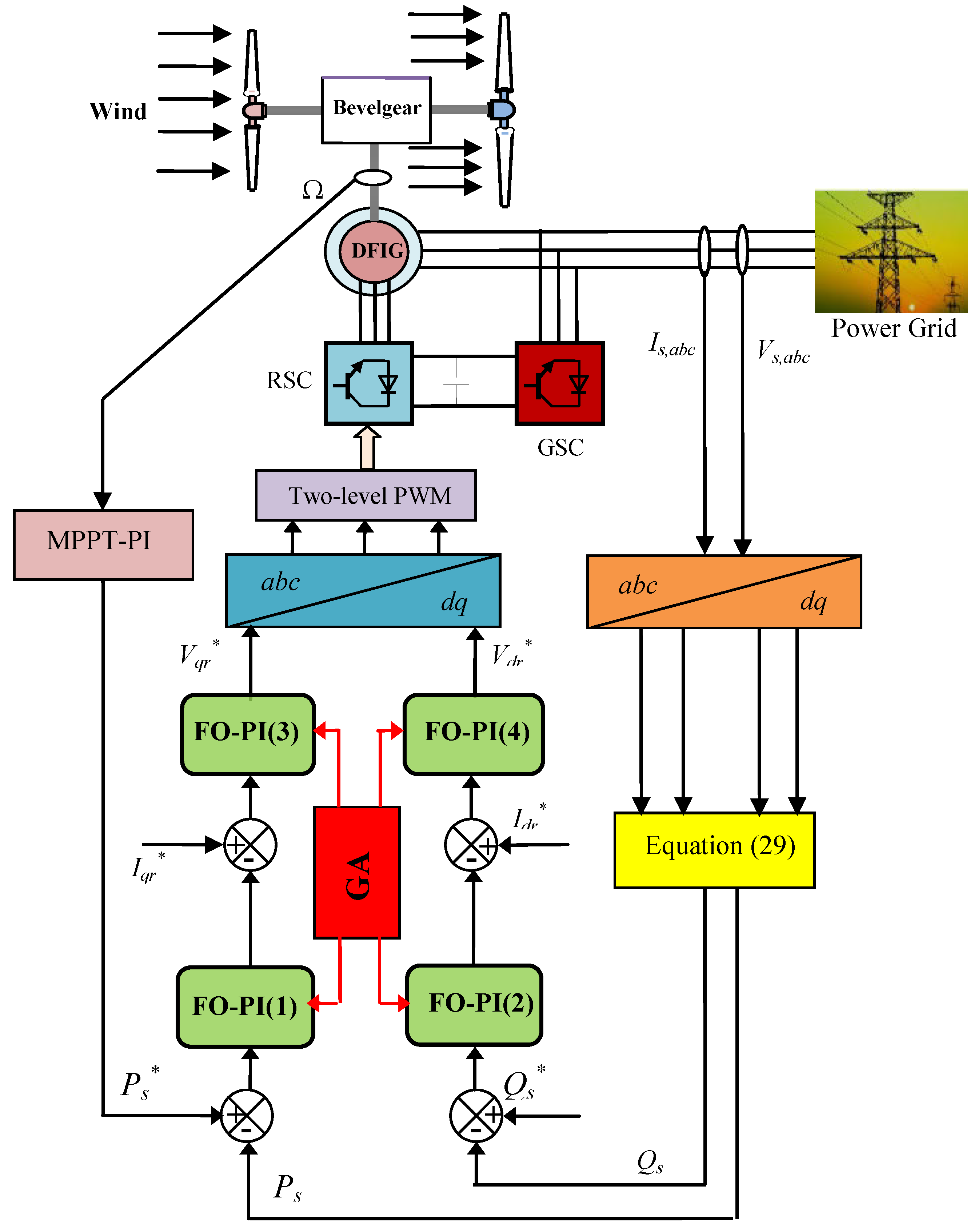
Figure 2 illustrates the cascaded fractional-order PI architecture used for controlling the power outputs of the DFIG-MRWT system. The figure highlights two FO-PI controllers optimized via GA for setting the reference value of the direct rotor voltage (
Vdr∗), alongside two additional FO-PI controllers responsible for establishing the reference value of the quadrature rotor voltage (
Vqr∗).
The CFO-PI approach was proposed to enhance power and current quality while improving system robustness, leveraging the advantages of fractional-order PI control. This strategy is characterized by its high robustness and reliable operational performance, making it a suitable and dependable solution in advanced control applications.
As illustrated in
Figure 2, the implementation of four FO-PI controllers makes this approach more intricate than the conventional DPC-PI method. A notable strength of the CFO-PI strategy is its integration of a larger number of tunable gains, which represents a significant advancement over traditional DPC-PI approaches. However, the increased complexity and the higher number of gains are identified as the primary challenges associated with this method.
The impact of sensor noise on the performance of the proposed CFO-PI approach is an important practical consideration. Due to their inherent memory effect and frequency-dependent behavior, fractional-order integrators can be more sensitive to high-frequency measurement noise compared to classical integer-order controllers. In particular, noise components may be amplified within certain frequency ranges, potentially degrading control accuracy and stability. To address this issue, appropriate design measures must be considered, including the use of low-pass filtering, careful selection of the fractional orders, and bandwidth limitation of the control loops. In addition, discretization methods used for implementing fractional operators should be chosen to ensure numerical robustness and noise attenuation. With these considerations, the adverse effects of sensor noise can be effectively mitigated, allowing the proposed CFO-PI approach to maintain its superior dynamic and steady-state performance under realistic operating conditions.
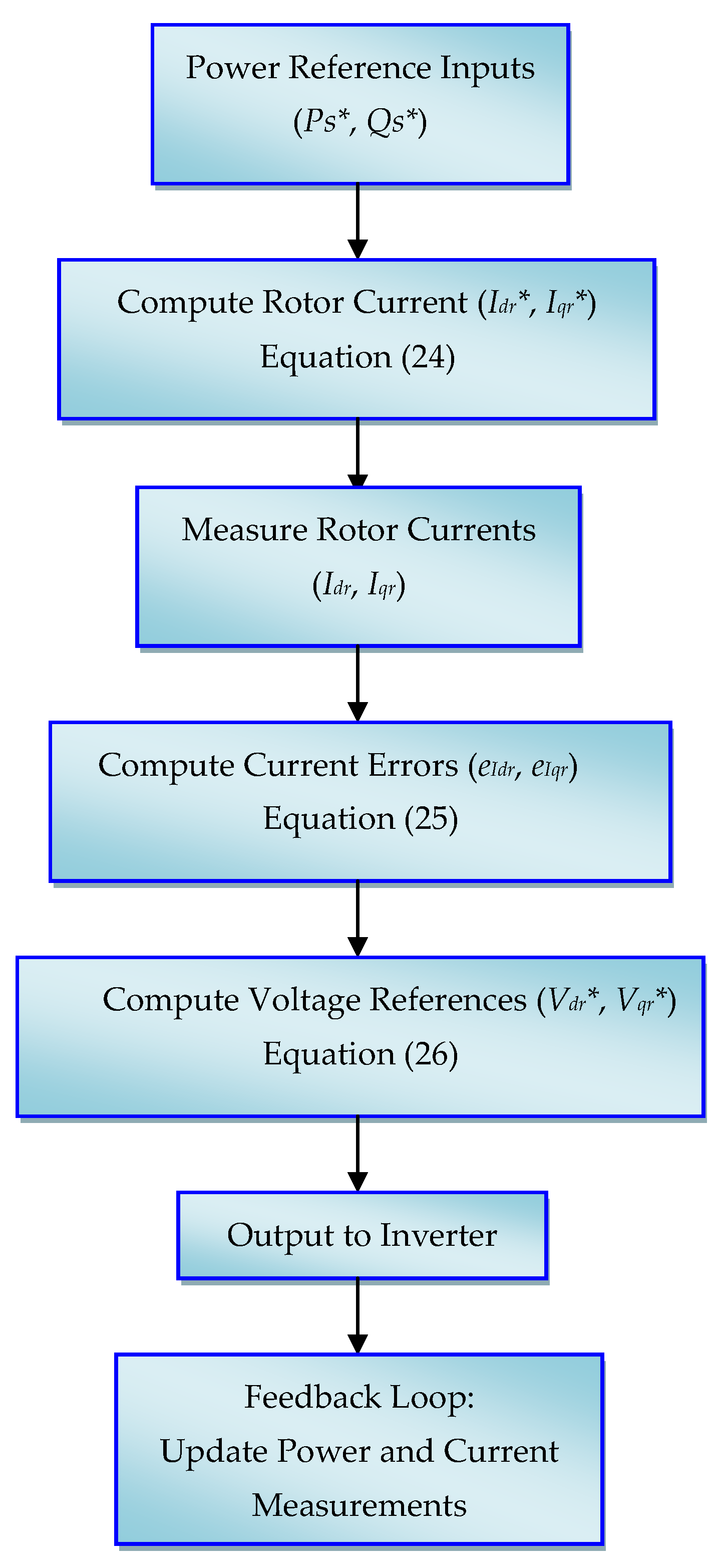
The flowchart of the CFO-PI approach (
Figure 3) illustrates the systematic process of converting power references into voltage signals for inverter actuation. The control begins with the
Ps and
Qs references (
Ps∗,
Qs∗), which are compared with measured power to generate power errors. These errors are then processed through fractional-order PI controllers to compute the rotor current reference values (
Idr∗,
Iqr∗) according to Equation (24). Measured rotor currents (
Idr,
Iqr) are subsequently used to determine the current errors (
eIrd,
eIrq) as expressed in Equation (25). These current errors are then fed into a second stage of fractional-order PI controllers to generate the voltage reference signals (
Vdr∗,
Vqr∗) based on Equation (26). Finally, the voltage references are sent to the inverter, while a feedback loop continuously updates the measurements of power and currents, ensuring accurate tracking and robust dynamic performance. This flowchart highlights the cascaded structure of the controller, the role of fractional-order integration in enhancing response and ripple suppression, and the closed-loop feedback mechanism critical for practical power system applications.
The CFO-PI approach is designed to compute voltage reference values based on power ratings. Initially, the rotor current reference values are determined, which are subsequently used to derive the voltage references. The calculation of these currentsis facilitated by Equation (24).
Reference values for the rotating current are determined to identify the current error. This error is determined according to Equation (25).
The reference values for the voltage are determined based on the reference values for the current. The determination of these reference values for the voltage is achieved through the application of Equation (26).
The flux value can be derived from the voltage using Equation (27) [
61]. This method can be relied upon for estimating power outputs in the designed approach.
On the other hand, in the designed approach, the flux is used in the alpha-beta axis. This flux, according to the work done in [
62], is calculated according to Equation (28).
where
The flux (rotor and stator sections) in the d-q axis is calculated according to Equation (29) [
63]. The aforementioned equation demonstrates a direct correlation between the flux and the resistance of each component within the machine. This indicates that any alteration in the resistance value will concomitantly affect the flux.
After determining the power flux values, the power outputs can be estimated based on the work performed in [
64] using Equation (31). Power flow is necessary to determine the power error. This error is input to the controller designer, from whose values the reference voltage values (
and
) are determined and extracted.
A quantitative assessment of the computational load associated with the proposed control strategy (CFO-PI) was conducted to evaluate its practical feasibility. This analysis highlights the trade-off between the performance improvement achieved by a fractional-order PI controller (CFO-PI) and the additional computational cost it introduces. Specifically, the evaluation considers key factors such as the number of computations, the structure and number of control loops, and the sampling frequency required for real-time implementation. Compared to the traditional DPC-PI approach, the proposed method involves a greater computational load due to the application of fractional-order factors and sequential control stages. However, this increase remains within acceptable limits for modern digital processors and is justified by the significant improvements observed in terms of ripple reduction, overshoot reduction, and dynamic response. Therefore, the proposed control controller offers a suitable compromise between control performance and computational complexity, making it suitable for practical industrial applications.
Finally, a comparison is made in
Table 3 of the designed approach with some strategies found in the literature. A comparative analysis of the CFO-PI approach with conventional control strategies—including DPC with switching table, SMC, field-oriented control (FOC), adaptive control, and vector control—highlights the distinct advantages and trade-offs of each approach. The CFO-PI controller demonstrates superior dynamic response and effective suppression of current and power ripples due to the fractional-order integrators and cascaded architecture, while maintaining robustness against parameter variations and modeling uncertainties. In contrast, DPC with a switching table is simple and low-cost but sensitive to changes in system parameters and prone to oscillatory behavior. SMC offers high robustness and fast response but can introduce chattering and requires careful tuning, whereas FOC and vector control are widely adopted in industry, benefiting from mature implementation methods but depending heavily on accurate system models. Adaptive control provides flexibility to handle parameter variations but at the cost of higher computational complexity. Overall, the CFO-PI approach achieves a balanced compromise between performance, robustness, computational load, and ease of implementation, making it particularly suitable for practical industrial applications where high dynamic performance and ripple suppression are critical.
4. Results
This section aims to validate the design approach (CFO-PI) and its effectiveness compared to the DPC-PI approach. The approach’s effectiveness and robustness are verified using MATLAB 2014. This section also examines the operational performance of the design approach under normal and abnormal conditions, such as changing machine parameters.
To model the designed power system, a 1.5 MW DFIG MRWT is employed. The parameters for DFIG and the turbine used in this study are listed in
Table 4 [
61].
In these tests, the MPPT-PI approach was used to determine the reference value for active power. Furthermore, variable WS was used in the tests carried out to study the effectiveness and strength of the designed approach in improving the quality of current and power.
4.1. Initial Evaluation
In this initial investigation, the efficacy and efficiency of the designed approach (CFO-PI) are examined in the absence of defects. The MPPT-PI strategy is employed in this test to ascertain the reference value for
Ps and optimize WE gain. The results of this test are displayed in
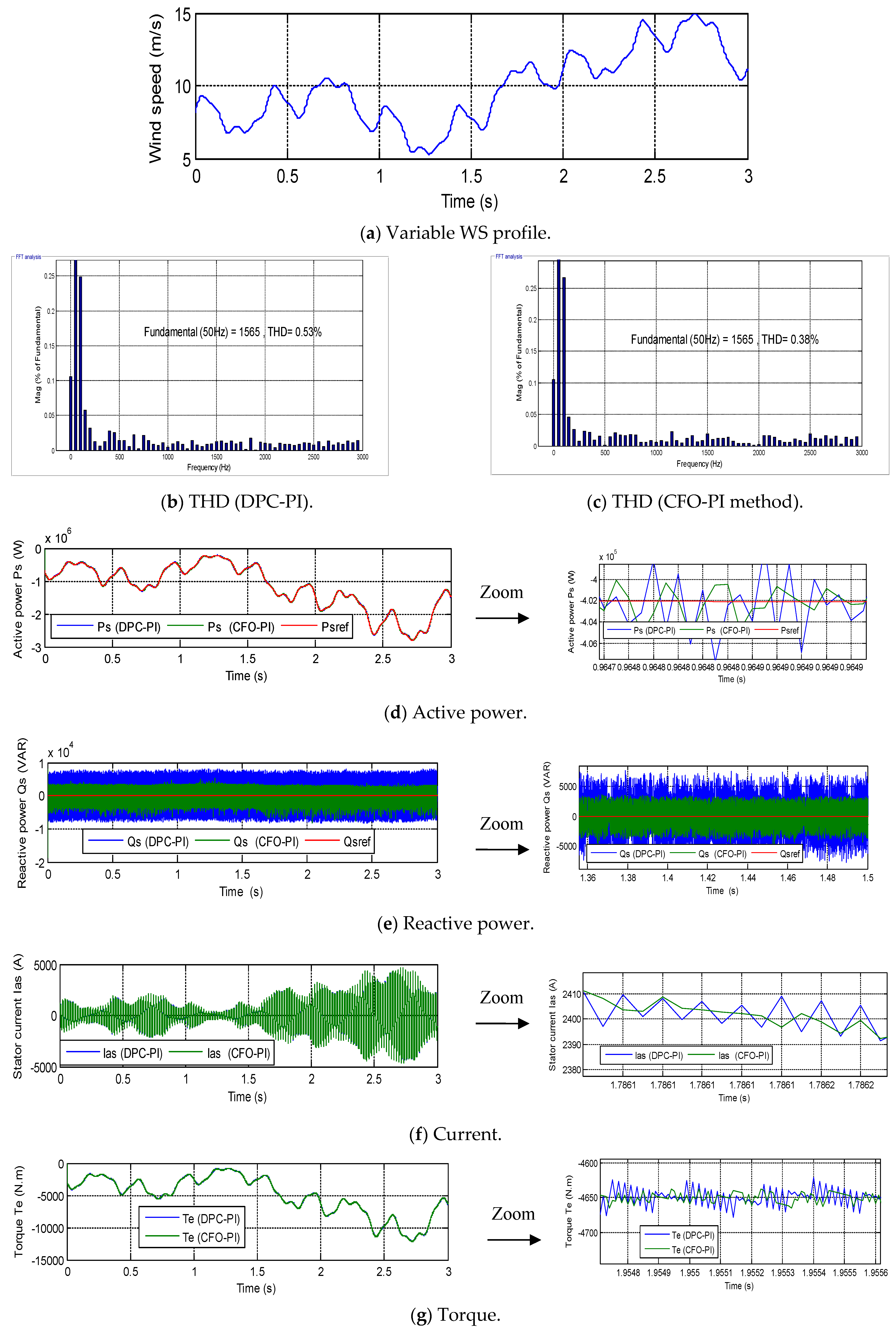
Figure 4. The numerical results for the two approaches in this test are shown in
Table 5. The WS variation pattern is represented in
Figure 4a.
Figure 4b,c illustrates the THD values obtained from the initial test for both controllers. The figures obtained indicate that the conventional DPC-PI approach yielded a THD value of 0.53%, while the designed approach produced a value of 0.38%. The values obtained from this analysis are indicative of the effectiveness of the designed approach in reducing THD in comparison with the conventional approach. This reduction is 28.30% compared to the traditional approach. Additionally,
Figure 4b,c demonstrates that the amplitude of the 50-hertz fundamental signal is equivalent for both approaches within the scope of this test. The findings indicate the efficacy of the devised approach in enhancing existing characteristics, thereby substantiating its potential as a promising solution.
Figure 4d,e illustrates the power variations observed during the initial test of the two controllers. The results demonstrate that the
Ps and
Qs outputs closely track the reference values, indicating a rapid dynamic response. As shown in
Figure 4d, the
Ps exhibit a parallel shift with the WS, whereas
Figure 4e shows that the
Qs remain essentially constant (zero) regardless of WS variations, although small ripples are present. The conventional DPC-PI method produces higher ripple levels compared to the proposed CFO-PI approach, a trend also observed for
Ps.
Figure 4f further depicts the behavior of the two control variables. The rotor current responds in accordance with WS variations due to the implementation of the MPPT-PI strategy. The current exhibits a sinusoidal fluctuation with a periodicity of 0.02 s, consistent across both controllers. Ripple analysis indicates that the CFO-PI method significantly improves current quality, reducing the ripple amplitude from 18A (DPC-PI) to 7A, corresponding to a 61.11% reduction.
Figure 4g presents the torque response under the two control strategies. The torque assumes negative values, confirming that the system operates in a power-generating state. Torque fluctuations are influenced by WS variations, and ripple effects were quantified at 24.50N·m and 20N·m for the conventional and proposed approaches, respectively. This represents an 18.36% reduction in torque ripple using the CFO-PI controller, demonstrating its superior ability to enhance the dynamic characteristics and overall performance of the power system studied compared to the conventional DPC-PI method.
Table 5 highlights the clear superiority of the cascaded fractional-order PI (CFO-PI) strategy over the conventional DPC-PI approach in terms of PQ and steady-state performance. The most notable improvements are observed in overshoot and SSE, with reductions reaching 85.75% and 85.46% for
Qs, and 50.59% and 72.60% for
Ps, respectively. These substantial reductions can be attributed to the additional tuning flexibility introduced by the fractional-order integral term, which provides an extra degree of freedom in shaping the system’s dynamic response. Unlike classical integer-order controllers, the fractional-order structure enables finer adjustment of phase and gain margins, resulting in improved damping characteristics and reduced oscillatory behavior. Consequently, the system exhibits smoother convergence toward reference values with minimal steady-state deviation.
Ripple reduction is similarly significant, with decreases of 54.44% for Qs and 61.71% for Ps. This improvement stems from the enhanced disturbance rejection capability of the fractional-order controller, which more effectively filters high-frequency oscillations inherent in DPC-based strategies. Reduced ripple content directly improves PQ, minimizes THD, and decreases thermal and electromagnetic stress on the generator and power electronic converters. In renewable energy systems—particularly grid-connected wind turbines—such ripple mitigation is critical for meeting grid code requirements and ensuring stable power injection.
Although the response time exhibits a relative increase (−71.87% for Qs and −52.91% for Ps, indicating slightly slower dynamics), this represents a deliberate and advantageous trade-off. The moderately slower transient response enhances system damping and stability, preventing aggressive control actions that typically cause overshoot and oscillations. In renewable energy conversion systems, where mechanical components are subject to continuous stress from wind variability, prioritizing stability and reduced oscillatory behavior over extremely fast response is often beneficial for long-term durability and reliability.
Overall, these results confirm that the CFO-PI strategy substantially enhances dynamic stability, steady-state accuracy, and PQ. Such improvements are crucial in renewable energy applications, contributing to improved grid compliance, extended equipment lifespan, and enhanced operational robustness of DFIG-based WE systems.
4.2. Second Evaluation
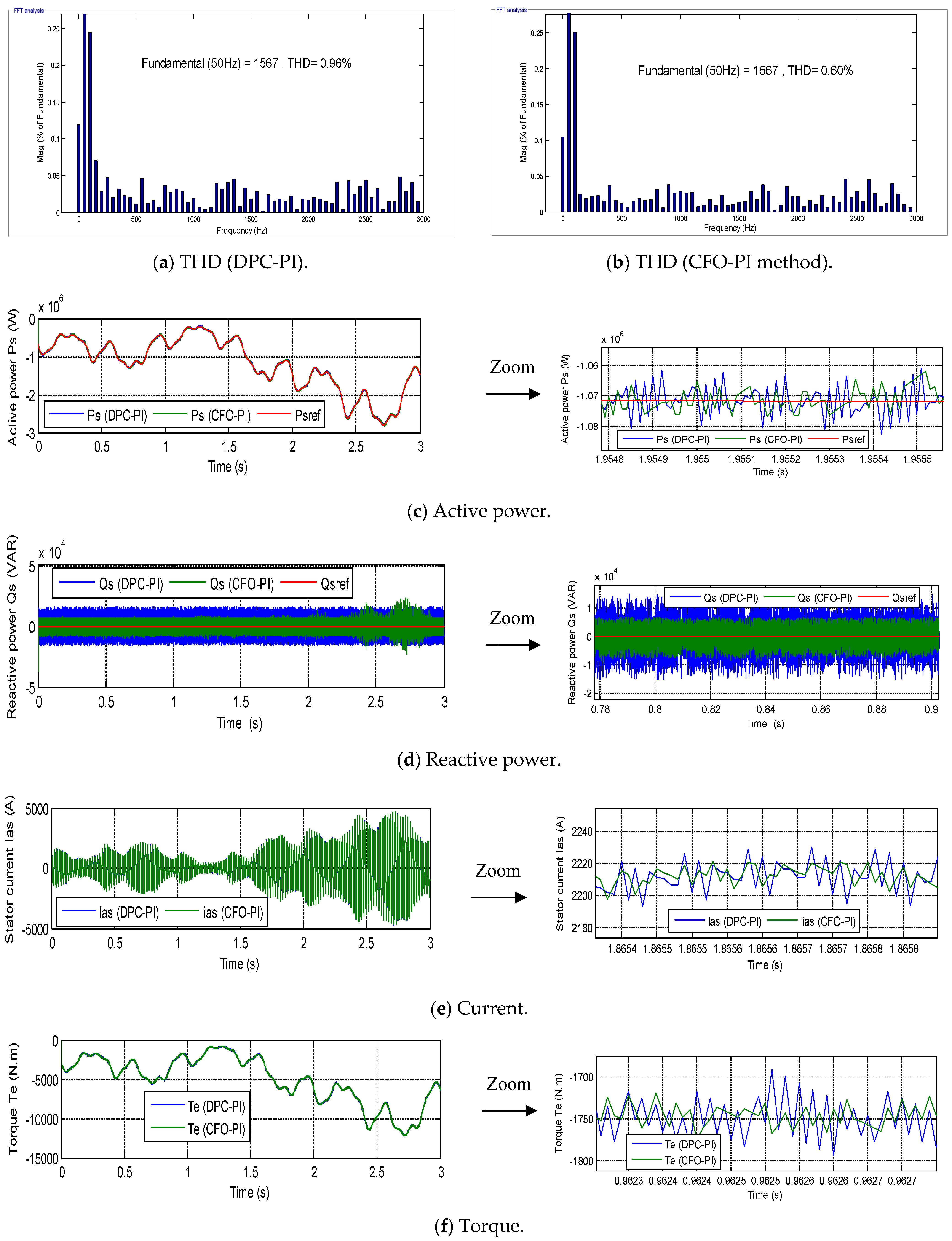
The second test differs fundamentally from the first to evaluate the robustness of the CFO-PI method relative to the conventional DPC-PI approach under variations in system parameters. In this test, the generator parameters were modified by doubling the resistor values and halving all coil values. The graphical results of this evaluation are presented in
Figure 5, while the numerical results are summarized in
Table 6.
Figure 5a,b shows the THD of the current for both control strategies. The THD values were 0.96% and 0.60% for the conventional and CFO-PI methods, respectively. Compared to the first test, THD increased substantially for both control techniques, indicating sensitivity to changes in machine parameters. Nonetheless, the CFO-PI method maintains a significantly lower THD, corresponding to a 37.50% reduction relative to DPC-PI, demonstrating its effectiveness in preserving current quality despite parameter variations. Furthermore, both controllers maintained an identical fundamental current amplitude of 1567A, indicating only minor changes in amplitude due to the parameter modifications.
Figure 5c,d depicts the
Ps and
Qs responses under the second test conditions. As shown in
Figure 5c,
Ps remains within the reference range despite the parameter variations, and a similar outcome is observed for
Qs in
Figure 5d. Although power ripples increased compared to the initial test, reflecting the influence of parameter changes, the CFO-PI controller achieved substantially lower ripple levels than the traditional DPC-PI approach.
Figure 5e presents the rotor current response for both controllers. Despite the altered machine parameters, the current fluctuates in accordance with WS, and the ripple period remains constant at 0.02 s, indicating that the temporal characteristics are unaffected by parameter changes. The current ripple reached 35A with DPC-PI and 15.40A with CFO-PI, representing a 56% reduction and confirming the robustness and efficacy of the proposed control technique under varying system parameters.
Figure 5f illustrates the torque response for the two control strategies during the second test. The torque remains negative, confirming that the system continues to operate in a power-generating state, and its variation correlates with WS, increasing and decreasing accordingly. Torque ripples increased compared to the first test, with values of 120 N·m and 63.85 N·m for the conventional and CFO-PI techniques, respectively. This corresponds to a reduction of approximately 46.79% in torque ripples using the CFO-PI method.
Overall, the results of the second test underscore the robustness, reliability, and effectiveness of the proposed CFO-PI strategy in maintaining high-quality power, minimizing ripples, and preserving dynamic performance under altered generator parameters, thereby confirming its viability as a promising solution for DFIG-based WE systems.
As shown in
Table 6, the CFO-PI approach demonstrated superior performance in Test 2 compared to the conventional DPC-PI method, highlighting the effectiveness of dynamic trade-offs in achieving optimal control outcomes. The most notable improvement is observed in the SSE, with reductions of 94.30% for
Qs and 55.56% for
Ps. This significant enhancement can be attributed to the fractional-order integral action, which provides higher low-frequency gain and an improved memory effect compared to classical integer-order integration. Consequently, the controller achieves more accurate reference tracking and minimizes long-term deviations—an essential requirement in grid-connected renewable energy systems, where precise regulation of
Ps and
Qs ensures voltage stability and compliance with grid codes.
Ripple levels are also substantially reduced, with decreases of 52.03% for Qs and 54.34% for Ps. These reductions indicate a marked attenuation of high-frequency oscillations in both power components. This improvement results from the enhanced damping and flexible frequency-domain shaping enabled by the fractional-order controller. Lower ripple directly translates to improved PQ, reduced THD, and decreased thermal stress on generator windings and power electronic converters. In renewable energy applications—particularly WE systems—such ripple mitigation supports extended equipment lifespan, reduced maintenance costs, and increased reliability under fluctuating operating conditions.
The CFO-PI controller exhibits slightly increased overshoot (−15.34% for Qs and −35.41% for Ps) and slower response times (−70% for Qs and −57.54% for Ps), reflecting a deliberately conservative tuning approach. By sacrificing rapid transient dynamics, the controller achieves smoother steady-state performance with reduced oscillatory stress. In practical renewable power systems, where mechanical components are continually subjected to wind variability, prioritizing stability and ripple reduction over extremely fast transients is often beneficial for mechanical durability and grid compliance.
Overall, the results of Test 2 confirm that the CFO-PI approach substantially enhances steady-state precision and ripple mitigation—key performance indicators for renewable energy control. These improvements contribute to stronger grid stability, higher PQ, and long-term operational robustness of DFIG-based WE conversion systems.
Table 7 represents the extent of change in the results of both ripples, response time, SSE, and overshoot of both techniques, with the percentage of change calculated (
Table 5 →
Table 6). The analysis of performance variations between normal and disturbed operating conditions reveals notable differences in the behavior of the DPC-PI and CFO-PI controllers. For overshoot, the DPC-PI strategy exhibits a significant increase in
Qs overshoot (1500 VAR → 2824.8 VAR), while its
Ps overshoot decreases (5120 W → 3070 W), indicating moderate sensitivity to parameter changes. In contrast, the CFO-PI controller shows a dramatic rise in overshoot for both
Qs (213.75 VAR → 3337 VAR) and
Ps, reflecting a substantial loss of damping capability under robustness test conditions. Regarding ripple, both controllers experience considerable increases for
Qs and
Ps, with the effect being more pronounced in CFO-PI, highlighting its strong dependence on accurate system modeling, whereas DPC-PI remains comparatively more robust. In terms of response time, DPC-PI maintains a constant value for
Qs and improves for
Ps (0.89 → 0.45 ms), while CFO-PI achieves slight to significant improvements in both variables; however, this faster response is likely due to more aggressive control action that compromises stability, as evidenced by increased overshoot. For SSE, DPC-PI suffers a substantial increase in
Qs error but improves for
Ps, whereas CFO-PI maintains relatively low SSE with slight degradation in
Qs and improvement in
Ps. Overall, these results indicate that CFO-PI is the most affected by parameter variations due to its model-based nature, leading to significant degradation in transient performance, while DPC-PI demonstrates better robustness despite increases in ripple and reactive power SSE.
The comparative analysis between
Table 5 and
Table 6 highlights the impact of parameter variations on the performance of the DPC-PI and CFO-PI control strategies under robustness test conditions.
Under normal operating conditions (
Table 5), the CFO-PI strategy exhibits superior performance in terms of overshoot, ripple reduction, and SSE, particularly for
Qs. This is mainly due to its model-based structure, which allows better decoupling and precise tracking when system parameters are accurately known. In contrast, the DPC-PI controller shows higher ripple and SSE, but maintains relatively fast response times.
However, when system parameters are perturbed (
Table 6), a significant degradation in performance is observed for both controllers, with more pronounced effects on the CFO-PI strategy. Specifically, the overshoot of the CFO-PI method increases dramatically, especially for
Qs, where it rises by more than 1400%. This sharp increase indicates a loss of damping and reduced stability margins due to parameter mismatch. Similarly, ripple values for CFO-PI nearly double, confirming its sensitivity to model inaccuracies.
On the other hand, the DPC-PI method demonstrates comparatively better robustness. Although ripple and SSE (for Qs) increase under disturbed conditions, the overall transient behavior remains more stable than that of CFO-PI. Notably, the response time of DPC-PI remains unchanged for Qs and improves significantly for Ps, suggesting that its control structure is less dependent on precise system parameters.
Regarding steady-state performance, CFO-PI maintains relatively low SSE despite parameter variations, particularly for Ps, whereas DPC-PI experiences a substantial increase in SSE for Qs. This indicates that while CFO-PI is more accurate in steady-state tracking, it compromises transient performance under uncertainty.
Overall, the results demonstrate that the CFO-PI method is highly sensitive to parameter variations due to its reliance on an accurate system model. In contrast, the DPC-PI technique exhibits better robustness, maintaining acceptable performance even under perturbed conditions, albeit with increased ripple and SSE.
In conclusion, for applications where system parameters are uncertain or subject to variation, the DPC-PI strategy is more reliable. Conversely, CFO-PI is preferable in well-modeled systems where high steady-state accuracy is required.
4.3. Third Evaluation
The third test differs entirely from the tests performed above. In this test, an isolated comparison of factors is studied to separate the effect of PWM from the effect of the CFO-PI technique.
In this test, the separate cases are identified as follows:
Case 1: Conventional controller (e.g., DPC-PI) with normal PWM.
Case 2: Proposed CFO-PI controller without PWM effects—this can be simulated by assuming ideal voltage references (continuous voltage) so that the controller’s performance is seen independently of switching.
Case 3: CFO-PI controller with actual PWM, showing the combined effects of the controller and modulation.
A simulation is performed for each scenario, measuring key metrics such as Ps/Qs ripple, current ripple, and tracking error. Graphs and reduction ratios are also generated.
Scenarios 2 and 3 are compared to determine the additional impact of PWM on performance. Additionally, scenarios 1 and 2 are compared to assess the controller’s contribution independently of PWM.
- A.
Case 1: Scenarios 1 and 2
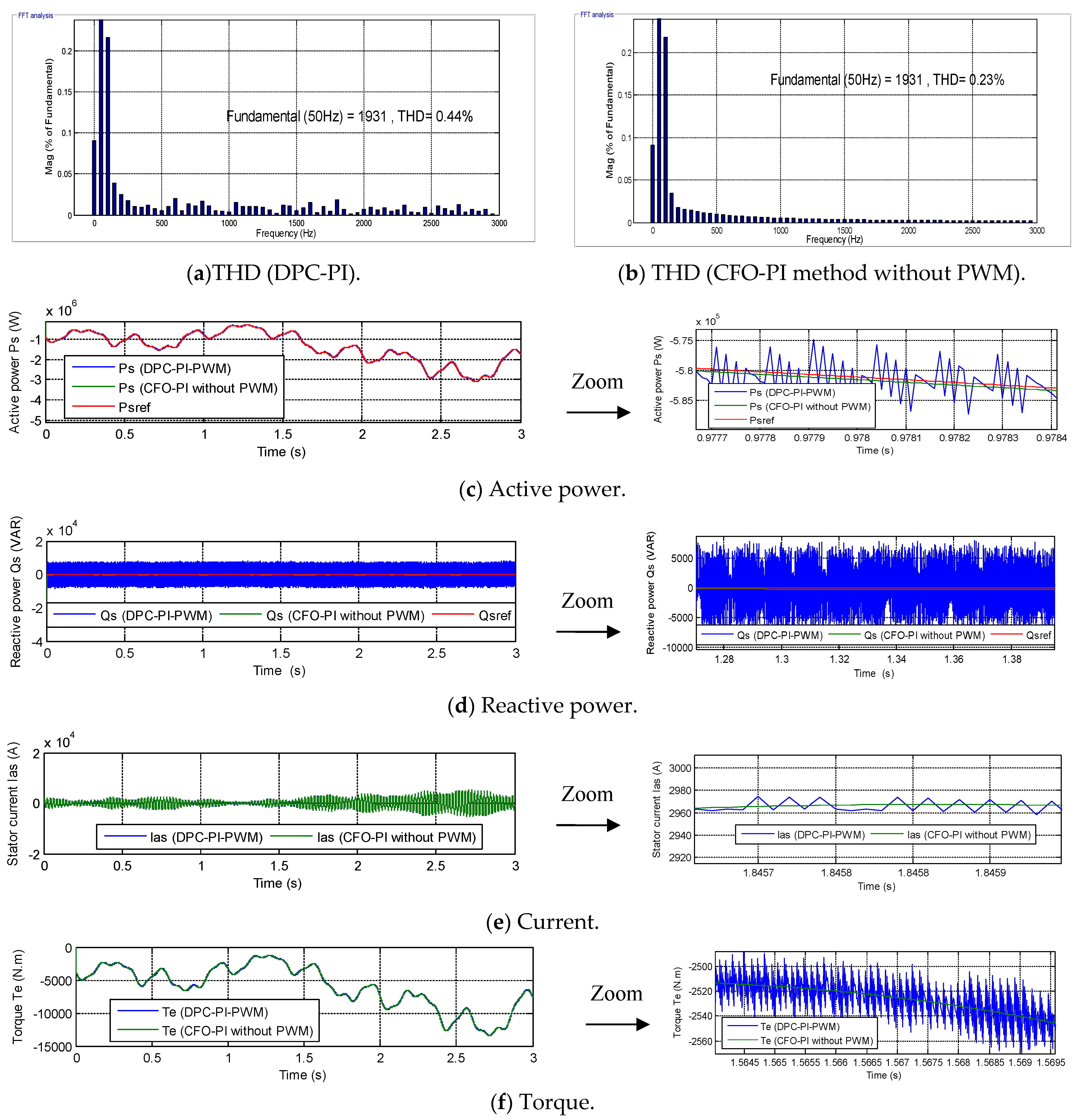
In this case, the traditional approach based on the PWM method is compared with the CFO-PI strategy without PWM. The results of this test are shown in
Figure 6, while the numerical results are shown in
Table 8.
Figure 6a,b represents the THD of current for the two control techniques during the third test (Scenarios 1 and 2). This value was 0.44% when using DPC-PI and 0.23% when using the CFO-PI method without PWM. These values indicate that the THD is significantly lower when using the CFO-PI method without PWM compared to the DPC-PI approach. This reduction is 47.72%. This percentage indicates the high effectiveness of the CFO-PI approach in improving current quality without using PWM.
Figure 6c,d represents the change in
Ps and
Qs for the two controllers in the third test (Scenarios 1 and 2). These power values remain well-tracked by the references, with the
Ps changing according to WS when using the CFO-PI method without PWM. However, a ripple is observed in the power outputs. This ripple is significantly higher when using the conventional DPC-PI method compared to the CFO-PI method without PWM. Therefore, omitting the PWM strategy allows for a substantial reduction in power ripple.
Figure 6e,f represents the variations in both current and torque for the two controllers in the third test (Scenarios 1 and 2). These figures illustrate that the current and torque continue to vary with WS, with the current exhibiting a sinusoidal pattern and a period of 0.02 s for both controls. Conversely, the torque (
Figure 6f) remains negative for both control techniques, indicating that the system is transmitting power to the grid.
Figure 6e,f demonstrates that the CFO-PI method without PWM significantly reduced torque and current ripples compared to the DPC-PI. The current ripples in this test were 3.3 A and 0 A for the conventional and CFO-PI methods, respectively. Therefore, the CFO-PI method without PWM reduced current ripples by 100% compared to the DPC-PI method. On the other hand, torque ripples were estimated at 54.50 Nm and 0.5 Nm for the DPC-PI approach and the CFO-PI method without PWM, respectively. These ripples are 99.08% low. These figures indicate the effectiveness and efficiency of the CFO-PI method without PWM in improving current and torque quality, making it a promising solution.
Table 8 presents the reduction rates obtained in Test 3 (Scenarios 1 and 2) by comparing the traditional DPC-PI method with the CFO-PI approach without PWM for
Ps and
Qs. The results demonstrate that the CFO-PI, without the PWM method, considerably improves several performance indicators. For overshoot, the values decrease from 3930 W to 1500 W for
Ps and from 3813.10 VAR to 300 VAR for
Qs, corresponding to reduction rates of 61.83% and 92.13%, respectively. A significant improvement is also observed in ripple reduction, where the ripples drop from 14,000 W to 200 W for
Ps and from 16,000 VAR to 280.50 VAR for
Qs, achieving reductions greater than 98%. Regarding the response time, the CFO-PI without the PWM technique reduces the response time for
Qs from 1.15 ms to 0.13 ms, representing an improvement of 88.69%. However, for
Ps, the response time increases from 1.15 ms to 2.72 ms, resulting in a negative reduction ratio (−57.72%), which indicates a slower dynamic response in this specific case. In terms of SSE, the CFO-PI without the PWM method significantly enhances the accuracy of the system, decreasing SSE from 1500 W to 300 W for
Ps and from 5000 VAR to 40.31 VAR for
Qs, corresponding to reductions of 80% and 99.19%. Overall, these results confirm that the CFO-PI without the PWM approach greatly improves overshoot, ripple mitigation, and steady-state accuracy, while slightly compromising the response time of
Ps.
- B.
Case 2: Scenarios 2 and 3
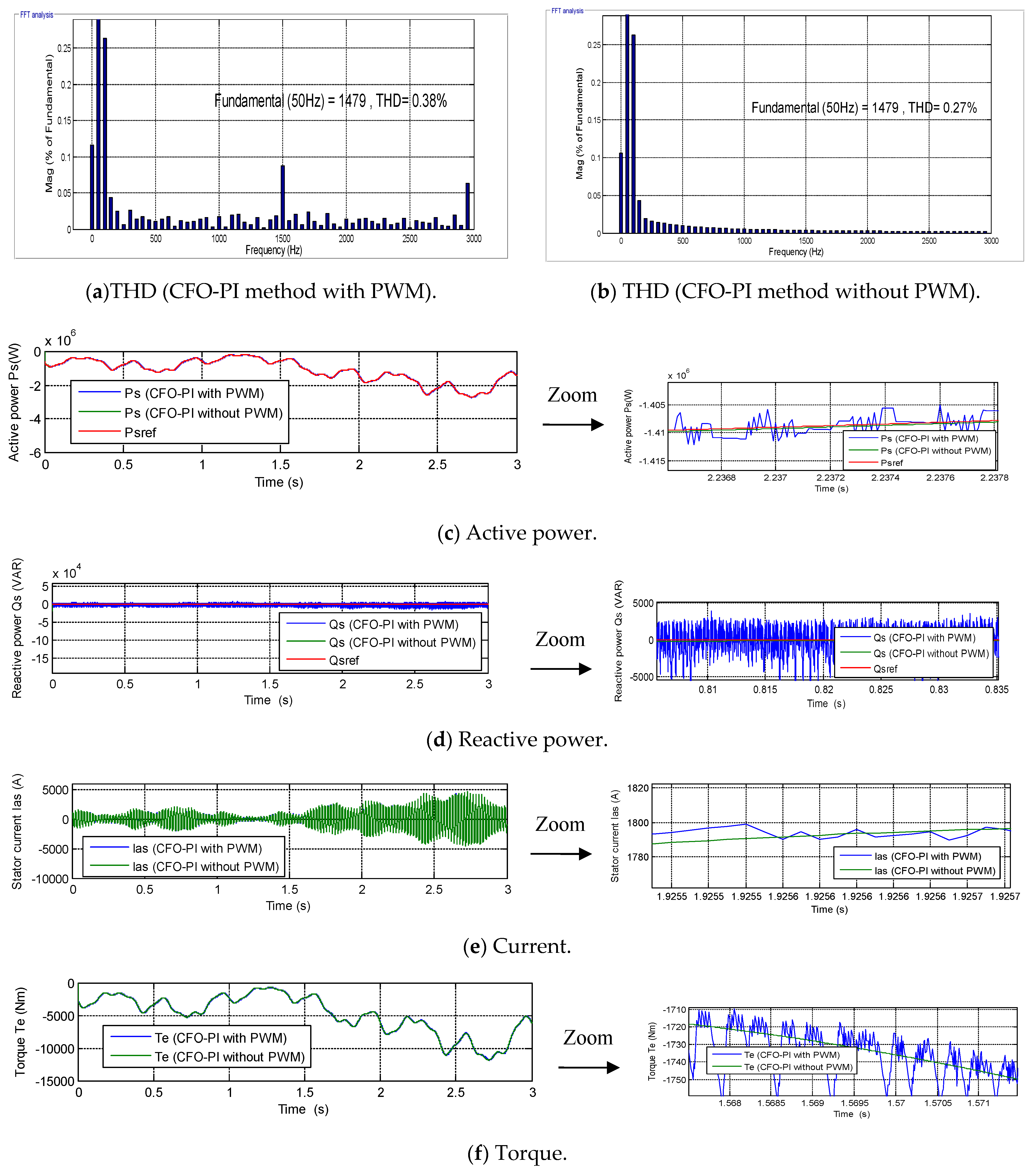
This test differs from the test performed in the first scenario (Scenarios 1 and 2). In this test, the performance of the CFO-PI approach without PWM is compared with that of the CFO-PI approach with PWM to determine the impact of the CFO-PI controller on performance. The variable WS used in the first test is employed in this test. The results for this scenario are shown in
Figure 7, while the numerical results are listed in
Table 9.
Figure 7a,b represents the THD of current for controls in Scenarios 3 and 2. These figures show that not using the PWM strategy positively affects the THD of current, significantly reducing it. Therefore, it can be concluded that using PWM negatively affects the THD of the current. In this case, the THD of the current was 0.38% when using the CFO-PI method with PWM, while it was 0.27% when using the CFO-PI method without PWM. Thus, not using the PWM strategy reduces the THD by 28.94%. This percentage indicates the significant impact of the PWM strategy on the THD and, consequently, on current quality. Current quality is directly affected by the PWM strategy, necessitating future research to find a more effective alternative to PWM.
The power outputs for the two controllers in this test are shown in
Figure 7c,d. These figures demonstrate that the power outputs follow the reference values well, with some ripple. As shown in
Figure 7c, the
Ps of the two control approaches remain negative and their value changes with WS, consistent with the observations in the tests above. On the other hand,
Figure 7d shows that the
Qs remains constant and is unaffected by changes in WS or the absence of PWM.
Figure 7c,d illustrates that the power ripples when PWM is not used are significantly lower compared to when PWM is employed. Therefore, not using PWM allows for a substantial improvement in PQ, making this a potentially reliable solution for the future.
Figure 7e illustrates the current variation using the CFO-PI approach with and without PWM. This figure shows that, whether using PWM or not, the current remains sinusoidal and its value varies with WS. Also, in both cases, the period remains 0.02 s. With PWM, the current ripple is 20 A, while without PWM, it is 0.5 A. Therefore, the current ripple is 97.50% lower than with PWM. Thus, CFO-PI without PWM significantly improves current quality compared to CFO-PI with PWM.
Figure 7f represents the torque variation with and without the use of the PWM strategy. As shown in this figure, the torque pattern in this test remains unchanged regardless of whether PWM is used or not; its value remains negative and takes the form of a change in WS. Furthermore, the torque ripple is significantly lower when PWM is not used compared to when it is. In this scenario, the torque ripple was estimated at 50 Nm and 2 Nm for CFO-PI with and without PWM, respectively. Not using PWM reduces torque ripple by approximately 96%. This percentage indicates the effectiveness of the CFO-PI approach in improving torque quality without the need for PWM.
Table 9 compares the performance of the CFO-PI with PWM and CFO-PI control without PWM methods in Test 3 (Scenarios 3 and 2) using several dynamic performance criteria for
Ps and Qs. The results clearly indicate that the CFO-PI controller without PWM significantly improves system performance compared with the CFO-PI with PWM approach. In terms of overshoot, the values decrease from 7310 W to 1550 W for
Ps and from 1413.89 VAR to 391.50 VAR for
Qs, corresponding to reduction ratios of 78.79% and 72.31%, respectively. A more pronounced improvement is observed in ripple reduction, where the CFO-PI method without PWM reduces ripples from 5400 W to 100 W for
Ps and from 16,000 VAR to 188 VAR for
Qs, achieving reductions exceeding 98%. The response time is also improved, decreasing from 2.56 ms to 2.02 ms for
Ps and from 2.91 ms to 1.30 ms for
Qs, representing reductions of 21.09% and 76.66%. Additionally, the SSE is substantially minimized, dropping from 1600 to 300 for
Ps and from 1779.4 to 46.09 for
Qs, corresponding to reductions of 81.25% and 97.40%. Overall, these results demonstrate that the CFO-PI technique without PWM provides superior dynamic and steady-state performance, particularly in minimizing ripples and SSE, thereby enhancing the overall stability and quality of power control.
Based on the results presented in
Table 8 and
Table 9, it can be concluded that the CFO-PI control strategy demonstrates a clear improvement in system performance compared with the conventional DPC-PI approach and also shows advantages when implemented without PWM. In
Table 8, the comparison between DPC-PI and CFO-PI without PWM (Scenarios 1 and 2) reveals substantial reductions in overshoot, ripples, and SSE for both
Ps and
Qs with reductions exceeding 60% for overshoot, around 98% for ripples, and up to 99% for SSE. Although the response time of
Ps slightly increases, the overall performance improvement remains significant, particularly in terms of power quality and steady-state accuracy.
Similarly,
Table 9 confirms the effectiveness of the CFO-PI without PWM configuration when compared with the CFO-PI with PWM (Scenarios 3 and 2). The results show notable reductions in overshoot, ripples, and SSE, while also achieving faster response times for both
Ps and
Qs. These improvements indicate that eliminating the PWM stage enhances the dynamic behavior and reduces oscillations in the power signals.
In general, the combined analysis of both tables demonstrates that the CFO-PI technique without PWM provides the best overall performance among the evaluated methods. It significantly improves dynamic response, minimizes oscillations, and enhances steady-state accuracy, making it the most effective solution for achieving stable and high-quality power control in the tested scenarios.
While the proposed control approach demonstrates improved Ps and Qs regulation, reduced ripple, and lower THD in simulation studies, its performance has so far been validated under a limited set of operating conditions. To more comprehensively assess robustness, future work should include stochastic wind profiles to capture realistic fluctuations, voltage dips, and grid disturbances to test fault tolerance, parameter uncertainties, and measurement noise to evaluate sensitivity to modeling errors and sensor inaccuracies, and, if feasible, hardware-in-the-loop or experimental tests to verify real-time performance and practical implementation. Incorporating these extended validation scenarios will provide stronger evidence of the controller’s reliability, robustness, and applicability in real-world DFIG-based WE systems, bridging the gap between simulation-based results and practical deployment.
As presented in
Table 10, a comparative analysis was conducted to evaluate the effectiveness of various control approaches in minimizing the SSE of DFIG-based WE systems. The results from the initial evaluation serve as the basis for this comparison.
The proposed CFO-PI technique demonstrates clear superiority in SSE reduction compared to most reported methods. For
Qs, the CFO-PI controller achieves an SSE reduction of 85.46%, exceeding all previously reported results. The closest competitor, ref. [
65] (Test 1) reports 78.44%, representing an improvement of 8.21%. Other studies, such as [
66,
67], report significantly lower reductions of 76.55% and 36.93%, respectively. Overall, the CFO-PI method improves
Qs regulation by 11.90% to 60.38% relative to these references, underscoring the robustness and effectiveness of the proposed CFO-PI strategy in
Qs control.
For
Ps, the proposed approach achieves a 72.60% SSE reduction, outperforming most reported methods, including [
66,
68,
69,
70], with improvement margins exceeding 50% in several cases. One exception is [
65] (Test 3), which reports a higher
Ps reduction of 87.50%, corresponding to a negative improvement of −17.02% relative to that specific test. Despite this single exception, the overall comparison confirms that the CFO-PI controller provides consistently high SSE minimization for both
Ps and
Qs, demonstrating its reliability and effectiveness for DFIG-based WE control applications.
Table 10.
A comparative analysis of related works in terms of reducing the SSE value of DFIG is hereby presented.
Table 10.
A comparative analysis of related works in terms of reducing the SSE value of DFIG is hereby presented.
| References | SSE Ratios | Improvement (%) |
|---|
| Qs | Ps | Ps | Qs |
|---|
| [66] | 36.93% | 35% | 56.79 | 51.79 |
| [68] | 42.14% | 47.57% | 50.69 | 34.47 |
| [71] | Test 1 | 46.86% | 63.96% | 45.16 | 11.90 |
| Test 2 | 45.48% | 78% | 46.78 | −6.92 |
| Test 3 | 43.21% | 60.03% | 49.43 | 17.31 |
| [67] | 76.55% | 28.76% | 10.42 | 60.38 |
| 24.62% | 30.48% | 71.19 | 58.01 |
| [65] | Test 1 | 78.44% | 45.83% | 8.21 | 36.87 |
| Test 2 | 52.22% | 56.52% | 38.89 | 22.14 |
| Test 3 | 48.75% | 87.50% | 42.95 | −17.02 |
| [69] | 35.48% | 62% | 58.48 | 14.60 |
| [70] | Test 1 | 38.32% | 50% | 55.16 | 31.12 |
| Test 2 | 39.68% | 40% | 53.56 | 26.22 |
| Proposed technique (Test 1) | 85.46% | 72.60% | - |
Table 11 compares the work performed with DFIG research in terms of THD values. This comparison uses the results of the initial test of the designer’s approach, where the THD value was estimated at 0.38%. The results presented in
Table 11 clearly demonstrate a significant improvement in current quality achieved by the proposed CFO-PI approach when compared with existing DFIG-based control strategies. Conventional methods, such as vector control used for harmonic filtering [
72], show that although THD can be reduced from highly distorted levels (29.41%) to below the IEEE limit of 5%, the performance remains limited relative to more advanced techniques. Nonlinear control strategies, including BC and SMC [
73], as well as super-twisting algorithms [
74], further enhance performance by reducing THD to the range of 1–3%. Similarly, hardware-based improvements using multilevel inverters [
75] and modulation strategies like the SVM method [
76] achieve THD values typically between 2% and 6%, while hybrid AI-based and multilevel approaches [
77] push the distortion slightly below 2%. However, even in optimized configurations and hybrid renewable systems [
78], THD generally remains above 3% in practical scenarios.
In contrast, the proposed CFO-PI method achieves an exceptionally low THD of 0.38%, which is substantially lower than all referenced studies. This indicates a superior capability in suppressing harmonic distortion and ensuring high-quality current injection into the grid. The result not only satisfies but significantly exceeds standard PQ requirements, highlighting the robustness and effectiveness of the optimization-based control design. Therefore, it can be concluded that the CFO-PI approach provides a highly efficient solution for harmonic mitigation in DFIG systems, outperforming both classical and advanced control strategies as well as hardware-based enhancements, and represents a notable advancement in improving PQ in WE conversion systems.
7. Conclusions
This study proposed an intelligent cascaded fractional-order PI control strategy optimized using a genetic algorithm for a 1.5 MW DFIG-based MRWT system. The primary objective was to enhance operational performance and PQ. The proposed approach was evaluated through simulation and compared with the conventional DPC-PI method to assess its effectiveness in reducing power and current ripples while improving steady-state accuracy.
Under nominal operating conditions, the simulation results show that the proposed control strategy provides improved performance. In particular, a 61.71% reduction in Ps ripple was achieved compared with the conventional DPC-PI approach, resulting in smoother power injection. In addition, the SSE of Ps was reduced by 72.60%, indicating improved tracking accuracy. For Qs, a 52.03% reduction in ripple was observed, along with an approximate 56% reduction in current ripple, reflecting enhanced waveform quality and reduced oscillatory behavior.
The parametric sensitivity analysis revealed that variations in generator parameters significantly affect system performance for both control strategies, as evidenced by increased THD and ripple levels. These results indicate that the system is inherently sensitive to parameter changes. However, despite this degradation, the CFO-PI controller consistently demonstrated superior performance compared to the conventional DPC-PI method. Notably, it achieved a 37.50% reduction in current THD, a 56% reduction in rotor current ripple, and a 46.79% reduction in torque ripple under perturbed conditions. Additionally, substantial improvements were observed in SSEs and power ripple attenuation.
Therefore, the results suggest that the proposed controller does not eliminate sensitivity to parameter variations but effectively mitigates their adverse effects and maintains better control performance relative to the conventional approach. In this sense, the CFO-PI strategy can be considered relatively robust, as it preserves acceptable performance and stability under parameter uncertainties.
The cascaded fractional-order structure provides increased flexibility in controller design, enabling improved steady-state precision and frequency-domain shaping. The use of GA-based optimization facilitates systematic parameter tuning and reduces reliance on manual adjustment.
It is important to note that these conclusions are based solely on MATLAB/Simulink simulations conducted under a limited set of operating conditions. Consequently, improvements related to durability, thermal stress reduction, and component lifetime should be regarded as indicative rather than experimentally validated.
Future work will focus on extended validation under more realistic conditions, including stochastic wind profiles, grid disturbances, parameter uncertainties, and measurement noise. Hardware-in-the-loop and experimental studies will also be conducted to further assess the practical feasibility and robustness of the proposed controller in real-world DFIG-based WE systems.