1. Introduction
Visual impairments are among the most widespread health conditions worldwide, affecting an estimated 2.2 billion people [
1], with more than 1 billion of them lacking access to appropriate services and technologies tailored to their needs. Such impairments severely impact the quality of life, restricting personal autonomy and, in severe cases, may result in complete dependence on external assistance [
2,
3,
4,
5]. Consequently, research has increasingly focused on supporting blind and visually impaired individuals (b/VI), particularly in navigation and mobility across unfamiliar environments where safety and autonomy are most at risk [
6,
7]. While sighted individuals can easily explore novel environments, designing an artificial system capable of safely guiding a visually impaired user is challenging. Providing effective navigation support requires acquiring environmental information (e.g., paths, distances, and various obstacle types), data processing in real time, and delivering intuitive feedback.
Over the past decade, electronic travel aids have evolved from basic ultrasonic devices into advanced wearable systems. Commercial examples include ultrasound-enhanced canes, wrist sonars, and tactile belts. These devices target different aspects of mobility, but they seldom offer a complete scene overview. For example, ultrasound canes, such as UltraCane [
8] and WeWALK [
9], can effectively identify hazards at head- and chest-level. However, they depend on ground contact to detect drop-off and provide narrow, direction-specific coverage that conveys “obstacle/no-obstacle” information rather than an overall layout or traversability. Wrist-worn sonars, such as Sunu Band [
10], are highly portable and translate distance from nearby obstacles into vibrotactile feedback, with ranges reported up to 5.5 m. However, a single feedback channel offers limited spatial information, often requiring significant user training to prevent overload. The tactile belt feelSpace naviBelt [
11] is excellent at conveying directional information and supporting spatial orientation. A ring of 16 vibrotactors gives continuous heading information, making paths and directions perceivable through vibrations around the waist; however, this device does not detect obstacles and must be combined with an additional sensing modality. On the research side, depth cameras coupled to vibrotactile arrays have been explored for obstacle localization and avoidance [
12,
13,
14], and simultaneous localization and mapping (SLAM) pipelines have been proposed specifically for b/VI navigation [
15]. Many of these systems share several practical limitations: sensitivity to strong ambient illumination (especially sunlight) [
12,
13,
14]; reduced throughput (less than 15 fps) [
12]; limited portability and comfort due to backpack-mounted laptops and battery packs [
12,
13]; and non–hands-free operation, alongside a limited number of recognizable obstacles due to the YOLO-based recognition that requires prior dataset collection and algorithm training [
14]. Several stereo vision systems have also been reported, but most face critical limitations: many require at least 100 ms to compute a single disparity map (capping throughput at approximately 10 fps) [
16,
17,
18]; some rely on external markers [
19,
20]; others integrate bulky or uncomfortable components for everyday use [
21,
22]. Consequently, real-world adoption remains limited.
Multiple reviews converge on persistent shortcomings [
23,
24,
25]. First, study populations often under-represent b/VI users: one review of 70 papers on electronic travel aids found that 51% relied on simulation, ~24% on blindfolded sighted, ~23% on b/VI participants, and only ~1–2% reached commercialization [
23]. Beyond under-representation, samples are frequently small or non-representative (e.g., less than six visually impaired participants [
12,
13]). Second, protocols and endpoints remain inconsistent: field trials, when present, are often sparse; obstacle-avoidance is tested on few, lightly populated routes [
12]—and task framing frequently prioritizes goal-directed navigation over general obstacle detection [
13], with limited reporting on movement quality or learning across repeated exposure [
24,
25].
What is missing is an affordable and comfortable aid that detects forward obstacles beyond narrow, single-beam coverage and sustains real-time operation on low-cost platforms across typical lighting conditions. Given its ability to infer scene geometry from passive image pairs without relying on active depth emission, stereo vision provides a cost-effective foundation for real-time obstacle detection in diverse lighting conditions. To address current gaps, we developed a compact, low-cost electronic travel aid that integrates a stereo camera, real-time SLAM, and vibrotactile feedback while logging user trajectories for offline analysis. The system enables direct comparison between two widely used depth estimation algorithms, allowing us to examine their relative suitability for real-time navigation on affordable, accelerator-free platforms. This scenario is representative of low-cost wearable implementations and provides a conservative lower bound on the computational resources required for real-time navigation support. We evaluated its ability to support safe and efficient navigation and obstacle avoidance in cluttered indoor environments. The study involved both b/VI and blindfolded sighted participants, combining quantitative measures of performance with indicators of movement quality and investigating learning across repeated trials. In doing so, we aim to demonstrate the feasibility of low-cost, real-time stereo-vision systems for navigation support without dedicated hardware acceleration.
Beyond practical feasibility, the contribution of this work is threefold. First, it provides user-centered validation in a population underrepresented in the Electronic Travel Aids literature blind and visually impaired participants tested under a controlled realistic indoor obstacle-avoidance protocol. Second, it extends evaluation beyond coarse collision-based outcomes by jointly quantifying safety, locomotor efficiency, and movement quality through obstacle-avoidance rate, walking speed, and trajectory smoothness (SPARC). Third, it compares user performance while using two widely used stereo-matching algorithms under real-time constraints on commodity CPU-only hardware, thereby informing the design of low-cost wearable assistive navigation systems.
2. Materials and Methods
2.1. Hardware
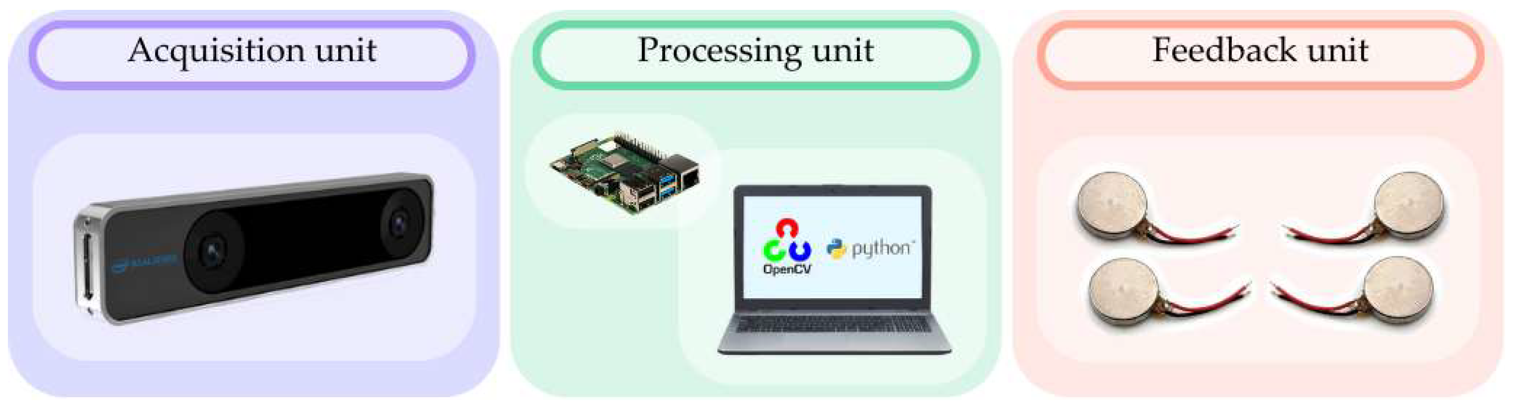
The hardware architecture comprises three main units—Acquisition, Processing, and Feedback—that operate in a continuous real-time loop (
Figure 1).
The Acquisition unit contains the Intel RealSense T265 (2019) camera [
26], which provides stereo images and 6-Degree of Freedom (DoF) tracking data. The T265 integrates multiple modules within a compact form factor (108 mm × 24.5 mm × 12.5 mm): a pair of monochrome global shutter CMOS sensors forming the stereo camera, an Inertial Measurement Unit (IMU), and the embedded Vision Processing Unit (Intel
® Movidius™ Myriad™ 2 MA215x; Intel Corporation, Santa Clara, CA, USA), connected via USB 3.1 Gen 1 Micro-B interface. The stereo sensors capture, at 30 fps, two 848 × 800 pixel wide-angle fisheye images, covering a 173° field of view. The stereo cameras have a baseline of 64.5 ± 0.15 mm, ensuring reliable disparity estimation. The integrated IMU includes a 3-axis accelerometer (±4 g at 62.5 Hz) and a 3-axis gyroscope (±2000°/s at 200 Hz), supporting robust 6-DoF tracking. The T265 runs a complete embedded visual-inertial SLAM pipeline and outputs the 6-DoF pose estimates (i.e., orientation and location) at 200 Hz.
The raw data streams (stereo images and 6-DoF camera pose estimates) are sent to a Raspberry Pi 4 Model B [
27] via a USB 3.1 Gen 1 Micro-B interface, which is part of the Processing unit. The Raspberry Pi is powered by a 10,000 mAh power bank rated at 5 V/3 A and mounted on an actively cooled heatsink to prevent thermal throttling during continuous operation. It handles data acquisition and communication, whereas the computationally intensive processing is performed on the Processing unit laptop (Asus VivoBook Pro N580V [
28], equipped with an Intel i7-class CPU, Intel HD Graphics 630 GPU, and NVIDIA GeForce MX150 with 2GB VRAM). Specifically, the Raspberry Pi transmits the information via a local wireless network to the laptop and receives the processed results for feedback generation. In the present experimental configuration, the laptop was not worn by the participant but connected to the same local wireless network as the Raspberry Pi.
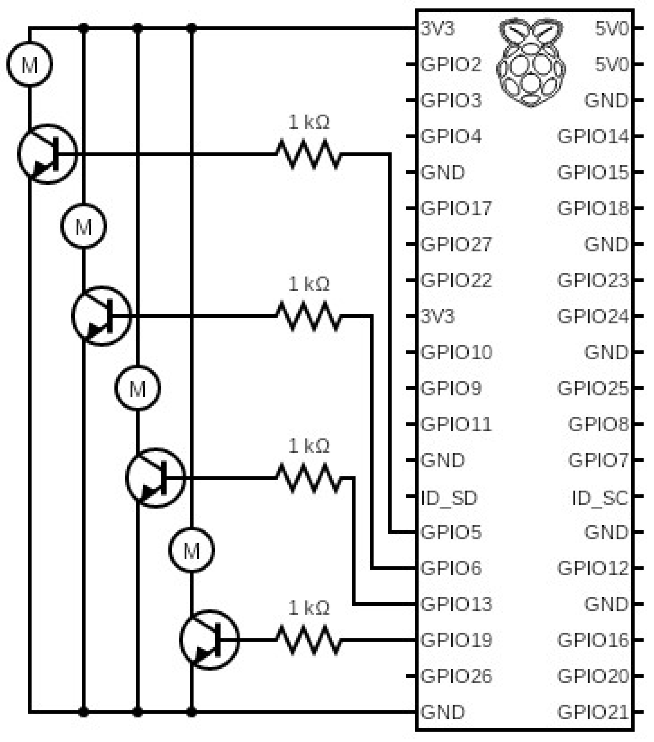
The Feedback unit consists of four coin-type eccentric rotating mass (ERM) vibration motors (Precision Microdrives Ltd., London, UK, model 310-117 [
29]) driven through Raspberry’s dedicated GPIO pins as shown in
Figure 2. They are selectively activated to deliver vibrotactile cues, notifying the user of obstacles in the surrounding environment [
30]. Each motor has a 10 ± 0.1 mm diameter and a height of 3.4 ± 0.1 mm, making them suitable for unobtrusive integration into wearable systems. At the nominal operating range (2–3 V), the motors reach frequencies of 200–240 Hz with amplitudes of 1.4–2.2 g, while maintaining an average current consumption below 40 mA [
31].
2.2. Software
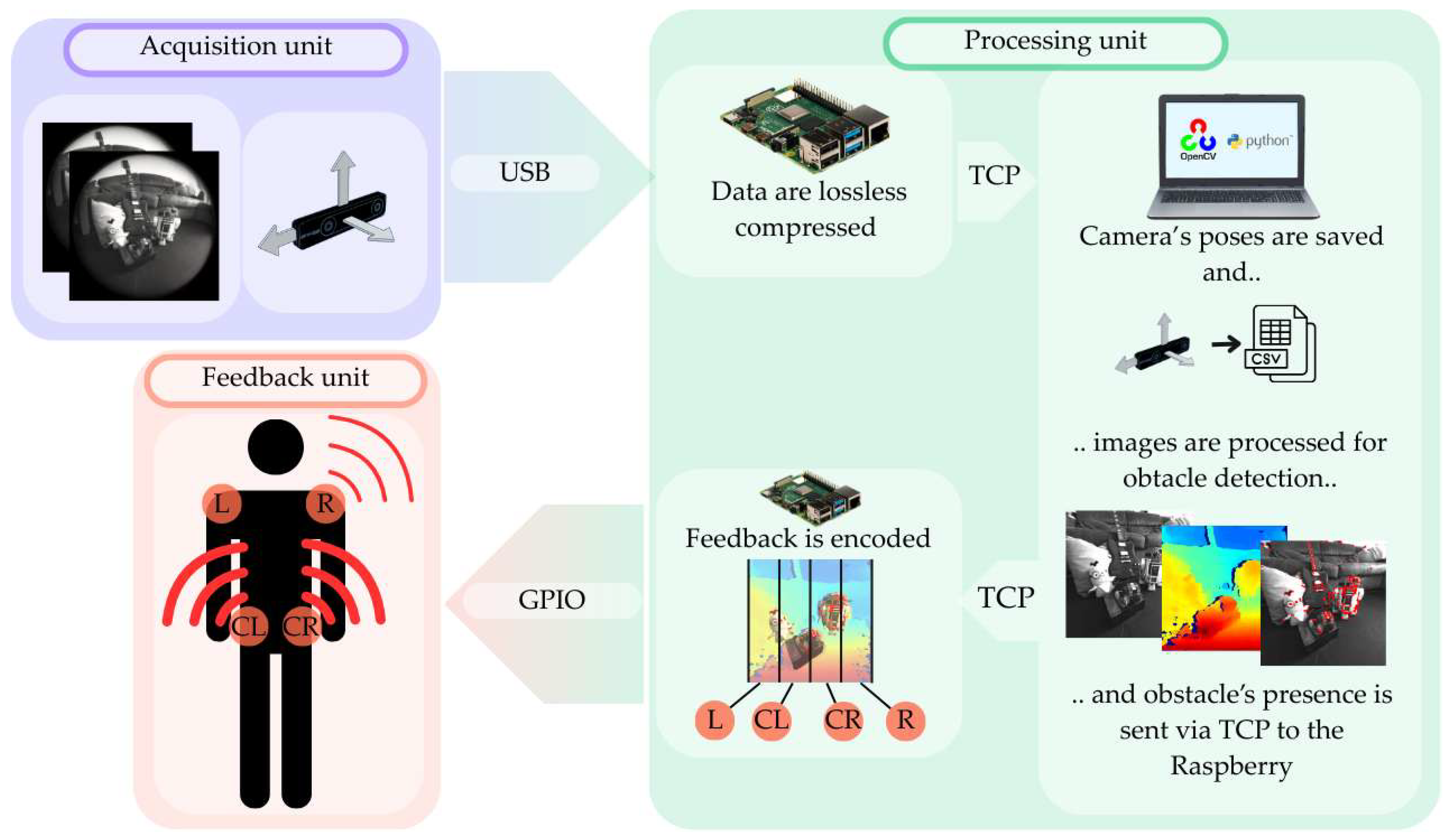
The software architecture followed a multi-stage processing pipeline, reflecting the temporal order in which data are acquired, preprocessed, transmitted, and used to generate real-time haptic feedback (
Figure 3).
2.2.1. Initialization
At startup, the Raspberry Pi initializes the T265 camera using the pyrealsense2 API [
32]. During this phase, the complete set of intrinsic and extrinsic calibration parameters for both fisheye sensors is retrieved. These parameters are stored locally and used for undistortion and rectification. Concurrently, the Raspberry Pi establishes a TCP WebSocket connection, with the laptop acting as the server to facilitate bidirectional data exchange. After initialization is completed, three dedicated threads are spawned to separately manage (i) stereo image acquisition, (ii) pose-SLAM tracking data, and (iii) vibrotactile output, i.e., the driving signals that activate the four motors. This thread-based architecture minimizes latency and prevents blocking between components of the pipeline.
2.2.2. Image Processing
Once the T265 begins streaming data, each stereo pair undergoes preprocessing directly on the Raspberry Pi. First, OpenCV fisheye model undistortion [
33] is applied using the distortion coefficients obtained at startup, followed by stereo rectification based on the intrinsic and extrinsic matrices. Performing these operations locally ensures that the transmitted image pairs are geometrically consistent and aligned, substantially reducing the computational burden on the laptop and improving the stability of subsequent disparity estimation. In parallel, pose-tracking data from the T265 are streamed continuously and logged by the laptop side for later analysis.
2.2.3. Disparity Computation
Given the T265’s streaming rate of 30 fps, each stereo pair must ideally be processed in less than 33 ms. To approach this constraint, the computationally intensive stages—dense stereo matching, disparity-to-depth conversion, and obstacle segmentation—are executed on the laptop rather than on the Raspberry Pi. The laptop receives the rectified stereo frames and processes them asynchronously, exploiting multithreading, optimized NumPy 1.18.5/OpenCV routines, and Python’s concurrent.fuures library [
34]. Disparity maps are obtained using block-matching algorithms optimized for fisheye-derived stereo data. Two stereo-matching algorithms were implemented using OpenCV: a local Block Matching (BM) method and a Semi-Global Block Matching (SGBM) approach.
BM is a purely local algorithm based on the Sum of Absolute Differences (SAD). For each pixel
(x, y) and candidate disparity (
d), the matching cost is computed within a squared support window centered at
(x, y) with side length
m + 1 pixels:
where
Il and
Ir denote the intensities in the left and right rectified images. In our implementation, we used an 11 × 11 support window, which provided a good trade-off between noise suppression and preservation of depth discontinuities. The estimated disparity corresponds to the value d minimizing
C(x, y, d). BM is computationally efficient and well suited for near real-time performance [
35,
36].
SGBM combines local SAD-based matching with global smoothness constraints. The per-pixel cost uses the Birchfield–Tomasi variant of SAD, which compares each pixel not only to its exact counterpart in the other image but also to linearly interpolated intensities of its immediate neighbors along the epipolar line. The resulting dissimilarity measure is less sensitive to sampling effects and small photometric shifts than plain SAD, improving robustness to sampling and illumination variations. Cost aggregation follows the Semi-Global Matching (SGM) formulation, in which the energy for a disparity configuration
D is:
where
p and
q are neighboring pixels,
dp and
dq their disparities,
P1 penalizes small disparity jumps, and
P2 >
P1 penalizes larger discontinuities. The optimal disparity map D minimizes the global energy function
E(D) along multiple scanline directions. SGBM yields disparity maps with fewer invalid or inconsistent regions, particularly around edges and low-texture areas, but at higher computational cost [
37].
2.2.4. Depth Computation and Temporal Filtering
The raw disparity map is denoised using a 3 × 3 median filter, which replaces each pixel with the median value in its 3 × 3 neighborhood. This non-linear filter suppresses disparity outliers and small speckle noise while preserving depth discontinuities at object boundaries. Depth
Z is then computed via the stereo geometry relation:
where
f is the focal length,
B is the stereo baseline, and
d is the disparity. Corner features are extracted from the rectified left image using a standard Harris corner detector [
38]. To compensate for potential missing matches in the disparity map, detected corners are dilated with an 11 × 11 kernel. A temporal filtering stage retains only corners persisting across consecutive frames, suppressing transient or “blinking” detections.
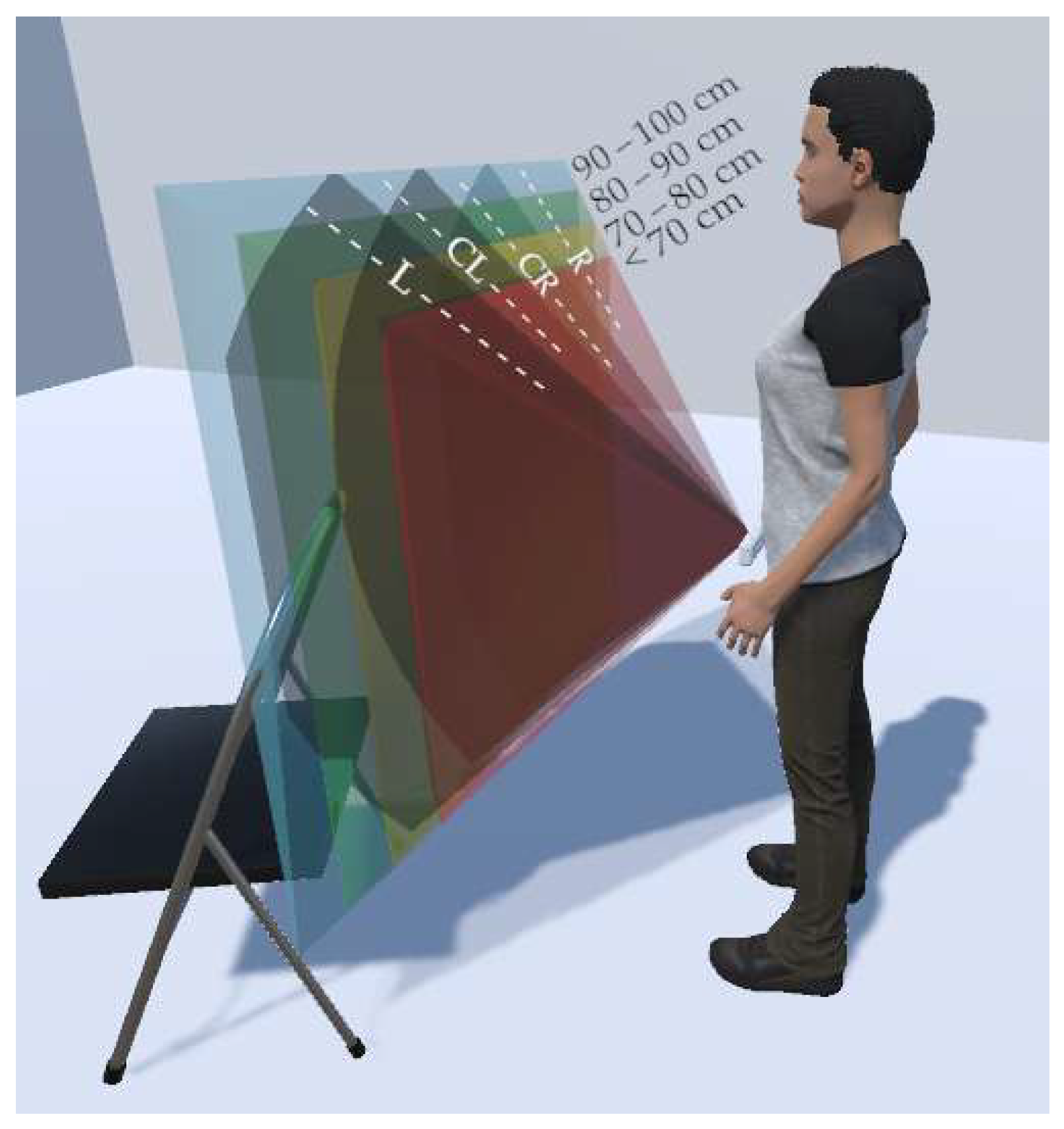
Each retained corner is then assigned a depth value and categorized into one of four distance bands:
<70 cm;
70–80 cm;
80–90 cm;
90–100 cm.
The four distance bands were chosen as a compromise between safety, depth resolution, and usability. The closer band corresponds to a collision zone, whereas the other ranges offer a 30 cm buffer in which obstacles can still be avoided with minor trajectory corrections. Splitting this buffer into three 10 cm bands allows us to encode a graded sense of proximity without introducing more levels than users can reliably distinguish in a vibrotactile pattern. These depth-band labels feed directly into the obstacle-detection stage (
Figure 4).
2.2.5. Obstacle Detection
The rectified image is partitioned into four vertical sectors corresponding to the four vibrotactile actuators: left (L), center-left (CL), center-right (CR), and right (R), as shown in
Figure 4. The two central zones are calibrated to form a 70 cm corridor at a viewing distance of 70 cm (~200 pixels within a 400-pixel image width and a 90° horizontal field of view), ensuring a minimum safe passage for the user [
39]; the lateral zones occupy the remaining columns. Each detected corner is assigned a depth from the co-registered disparity map. For each distance band, a specific depth mask selects obstacle pixels, which are then assigned to one of the four vertical sectors. A nearest-first rule is applied: detections from a closer distance (e.g., 70 cm) override those from a farther distance (e.g., 80–90 cm). The final sector–distance configuration is encoded into a predefined vibrotactile pattern and transmitted to the Raspberry Pi, which drives the vibrotactile actuators.
2.2.6. Vibration Display
The haptic interface comprises four vibration actuators positioned on the user’s skin. The shoulder actuators correspond to the lateral sectors (L and R), while the two hip actuators encode obstacles in the CL and CR regions. Obstacle information is transmitted as periodic square-wave vibration patterns (
Table 1): each actuator is either fully ON or OFF, and the duty cycle (ratio of ON time to total period) encodes the perceived urgency. For lateral actuators, duty cycle remains fixed at 0.05, providing reliable distance and directional cues without redundancy. For central actuators, the duty cycle is set at 0.1 and increases to 0.6 when obstacles are detected within 70 cm (see
Table 1), generating a more persistent and salient warning. During the ON phase, the vibration frequency varies between 208 Hz (nearest obstacles) and 212 Hz (farthest obstacles).
This encoding strategy provides an intuitive mapping between visual-space sectors, obstacle proximity, and perceived vibration intensity, enabling rapid interpretation by the user (
Figure 4).
2.3. Participants
A total of 24 individuals took part in this study. First, we tested the system with 14 sighted participants (7 females, 7 males, mean age of 26.0 years, SD = 1.96). Then, 10 participants with visual impairments (4 females, 6 males; a mean age of 44.7 years, SD = 15.7) were involved to assess the usability and effectiveness of the system under realistic end-user conditions. Nine of the ten b/VI subjects were completely blind. Among them, five were congenitally blind; three experienced a gradual progression to total blindness approximately five years before participation, and one participant (57 years old) lost vision at age 26 due to an optic-nerve pathology. The tenth participant began to lose vision approximately five years before this study due to a pathological condition and retains peripheral vision.
The two cohorts were not conceived as control and experimental groups but as distinct populations serving complementary purposes. In accordance with best practices for assistive-technology testing, initial validation was conducted with blindfolded sighted participants to ensure system safety, usability, and calibration before involving visually impaired users. The blindfolded sighted group, therefore, provided a baseline evaluation of the system behavior under naïve conditions, while the visually impaired group represented the intended end users, inherently older and more experienced in non-visual navigation.
2.4. Experimental Set-Up
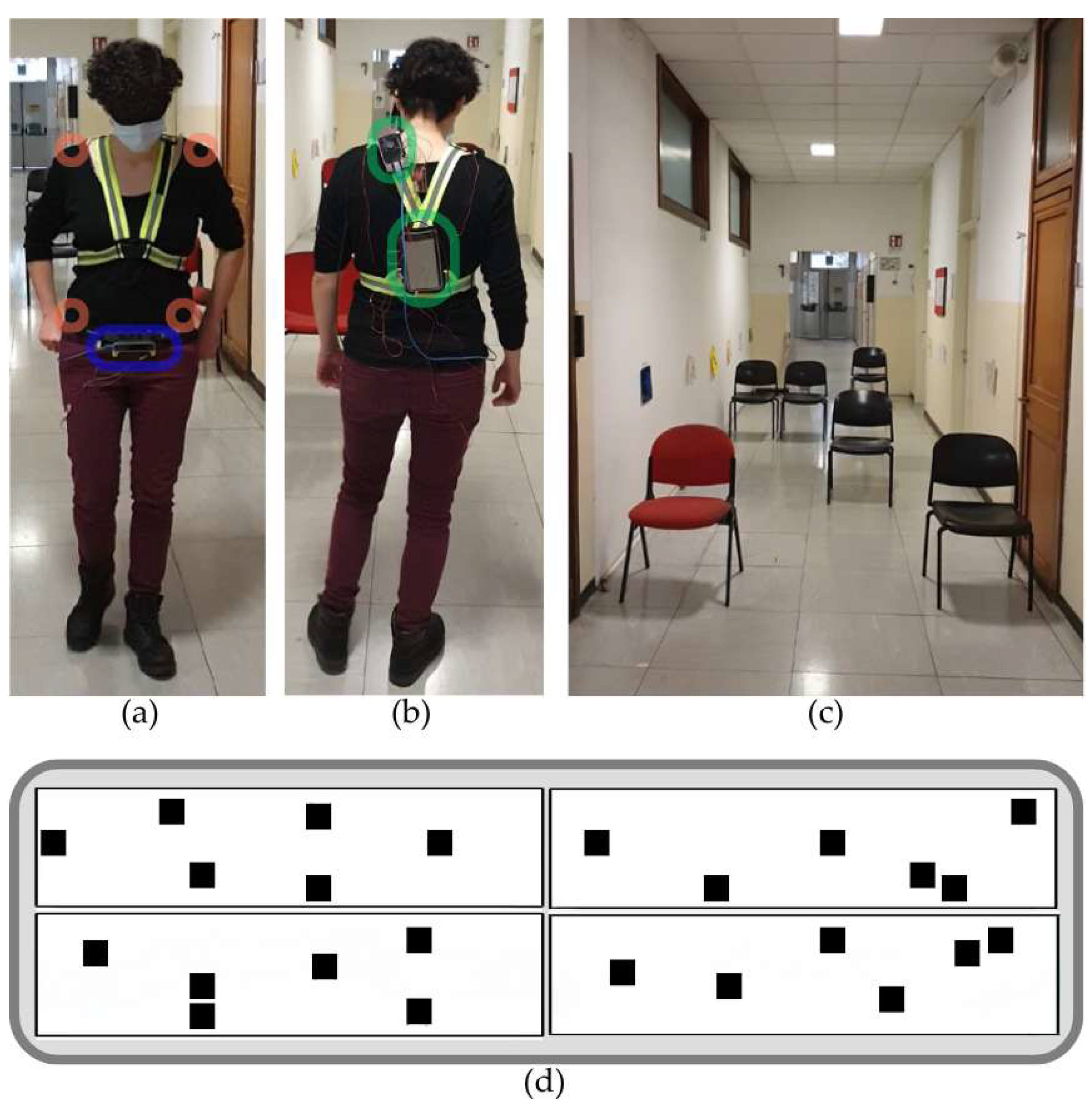
Participants wore the system that has been designed to be compact, lightweight, and ergonomically distributed across the body for maximum comfort (
Figure 5a,b). The configuration included:
a shoulder harness, containing both the Raspberry Pi and the power bank, ensuring a stable and unobtrusive power supply;
a belt at hip level to which the Intel RealSense T265 camera was secured in the frontal position, allowing a clear and stable forward-facing view;
four coin-type eccentric rotating mass actuators that were attached directly to the skin using disposable medical-grade adhesive tape: two units on the shoulders (L and R) and two on the abdomen (CL and CR). Direct skin contact was used to maximize the consistency and salience of vibrotactile perception and to avoid attenuation due to clothing layers.
The worn subsystem weighed approximately less than 450 g, including the Raspberry Pi 4 (~48 g), power bank (~200 g), Intel T265 camera (~60 g), four ERM actuators (~1.2 g each), and the shoulder harness and hip belt (~120 g).
The system was evaluated through indoor testing conducted in a 10 m long, 2.3 m wide corridor with a prefixed number of obstacles (
Figure 5c,d). The obstacles consisted of lightweight chairs (~80 cm in height, ~50 cm × 50 cm base footprint) oriented with the backrest facing the starting point. The chairs could be easily displaced by a push, ensuring that collisions were not dangerous. To ensure participant safety, the test area was cleared of any fixed elements or potential hazards such as wall-mounted objects (e.g., fire extinguishers).
To minimize auditory cues, all participants wore wax earplugs throughout the sessions. Furthermore, sighted participants and participants with residual vision wore opaque eye masks to prevent visual information from influencing their performance.
2.5. Experimental Protocol
Each experimental session was divided into two blocks of five trials each. The blocks differed in the disparity map algorithm used for obstacle detection. The order in which the algorithms were presented was counterbalanced across participants to avoid systematic bias. Before each block, participants wearing the device were allowed to move freely for 2–4 min in a corridor with obstacles. This familiarization phase aimed to help participants acclimate to the vibrotactile feedback system. Sighted participants could choose whether to explore with their eyes open or closed, while blind participants could use their white cane or their support aid if desired. Between blocks, participants were given a 5 min rest break.
Ten different obstacle layouts were presented to each subject to avoid path-learning effects. The layouts were designed to have comparable difficulty by enforcing shared structural constraints. Each configuration comprised six or seven obstacles placed to maintain a minimum free passage width of 70 cm and induce a similar number of lateral deviations (four to five lane changes) along the corridor.
2.6. Instructions for Participants
Participants were first instructed to traverse the corridor lengthwise, using the vibrotactile feedback to avoid obstacles. Each trial began with the experimenter’s verbal cue (“Start”) and ended with the “Stop” command, once the participant reached the end of the corridor. Participants were advised to avoid impulsive movements, such as kicking, and instead proceed in a careful and exploratory manner. While running was discouraged, they were free to probe the ground ahead with their feet to support navigation. To prevent self-occlusion during image acquisition, participants were instructed to keep their arms positioned outside the stereo camera’s field of view.
2.7. Data Analysis
Data from all ten navigation trials were analyzed to investigate the capability of the system to deliver vibrotactile navigation information and to identify the factors influencing user performance, including the disparity algorithm used (BM vs. SGBM) and the participant group (visually impaired vs. blindfolded sighted).
Three complementary performance metrics were extracted, each reflecting a distinct functional dimension of navigation:
Obstacle-avoidance rate. The primary safety metric was the obstacle-avoidance rate, defined as the ratio between the number of obstacles successfully avoided and the total number encountered. This measure captures the reliability and effectiveness of navigation under vibrotactile guidance.
Average walking speed. Locomotor efficiency was quantified by the average walking speed, computed over the full recorded trajectory. This metric reflects the user’s ability to maintain a natural and confident pace while simultaneously processing and responding to haptic feedback.
Trajectory smoothness. Movement smoothness was quantified using the Spectral Arc Length (SPARC) metric [
40,
41,
42], a frequency-domain measure designed to provide a robust and scale-independent estimate of movement regularity. SPARC relies on the principle that smoother movements tend to exhibit speed profiles dominated by low-frequency components, whereas irregular or hesitant movements distribute spectral energy over a broader and higher-frequency range band. The computation proceeded through the following steps. First, 3D position trajectories were smoothed using a 50-sample moving-average (rectangular) filter (~1 s window at ~50 Hz). The instantaneous speed magnitude was obtained by numerical differentiation of the filtered position signal. The magnitude spectrum was then computed via the discrete Fourier transform and peak-normalized by dividing by its maximum value, yielding a spectrum bounded between 0 and 1. The analysis was restricted to the frequency range [0, ω
c], where ω
c corresponds to the frequency at which the cumulative spectral energy reaches 95% of the total; this adaptive truncation removes high-frequency noise while preserving the behaviorally meaningful portion of the spectrum.
SPARC is calculated as the negative arc length of the normalized magnitude spectrum
(ω):
Higher SPARC values correspond to smoother and more continuous movements, whereas lower values indicate reduced smoothness and segmented motion. Descriptive analyses and visual inspections were first performed to verify that participants navigated safely and consistently across repeated trials, thereby confirming the baseline functionality of the system. Once this stability was established, statistical analyses were conducted to test the predefined hypotheses regarding learning and familiarization effects, algorithmic equivalence, and group-related differences, as detailed in the following section.
2.8. Statistical Analysis
Each dependent variable was analyzed using a mixed-design repeated-measures ANOVA with Algorithm (BM, SGBM) and Trial (T01–T05, five repetitions within each algorithmic block) as within-subject factors and Vision status (visually impaired vs. blindfolded sighted participants) and Starting algorithm (BM-first vs. SGBM-first) as between-subject factors, representing session order. Age was included as a covariate to control for demographic influences. Mauchly’s test was used to verify sphericity, and Greenhouse–Geisser corrections were applied when necessary. We corrected for multiple comparisons by using the Holm–Bonferroni correction. All analyses used Type III sums of squares with an alpha level of 0.05.
The same statistical framework was used to test the a priori hypotheses described below, each corresponding to specific main effects or interactions within the ANOVA model.
As an exploratory analysis, we also examined the Pearson correlation coefficient between walking speed and obstacle-avoidance rate within each group, collapsing across algorithms and trials.
2.8.1. Algorithmic Equivalence (H1)
Question: Does user performance differ between disparity algorithms (BM vs. SGBM)?
The main effect of the Algorithm in the ANOVA tests this hypothesis: a non-significant main effect indicates algorithmic equivalence, showing that both disparity-map methods support comparable functional performance. Any significant differences (interactions among factors) involving Algorithm are further inspected to determine whether they reflect genuine algorithmic differences or secondary factors such as group or session order.
2.8.2. Learning and Familiarization Independent of the Algorithm (H2)
Question: Does performance improve with experience? Is this improvement dependent on algorithm identity?
Within-session learning is assessed through the Trial main effect and the Algorithm × Trial interaction, indicating changes across the five consecutive trials performed with the same algorithm. Between-session familiarization is tested through the Algorithm × Starting Algorithm interaction. Since each participant experiences both algorithms (BM→SGBM or SGBM→BM), this interaction indicates whether performance with a given algorithm depends on whether it is executed in the first or second session. If this interaction reflects better performance during the second session—regardless of algorithm—it is interpreted as a session-related familiarization effect, consistent with rapid adaptation to the task and feedback. If, instead, the effect depends on the specific algorithm, it may indicate algorithm-dependent or order-specific differences. A non-significant interaction would be consistent with stable performance across sessions and algorithms.
2.8.3. Group Robustness (H3)
Question: Do b/VI participants outperform blindfolded sighted participants, and does this difference depend on the algorithm or session order?
The main effect of Vision status tests overall group differences, while Vision × Algorithm and Vision × Starting Algorithm interactions assess whether algorithmic or session effects differ between groups. Significant main effects of Vision indicate superior performance in b/VI participants, reflecting greater expertise in non-visual navigation. The absence of significant interactions would demonstrate that group differences are consistent and independent of algorithmic or order effects, supporting the robustness and generalizability of system performance.
3. Results
3.1. Baseline Functionality
All participants completed the navigation tasks without external assistance, confirming the basic usability and functional reliability of our vibrotactile navigation system.
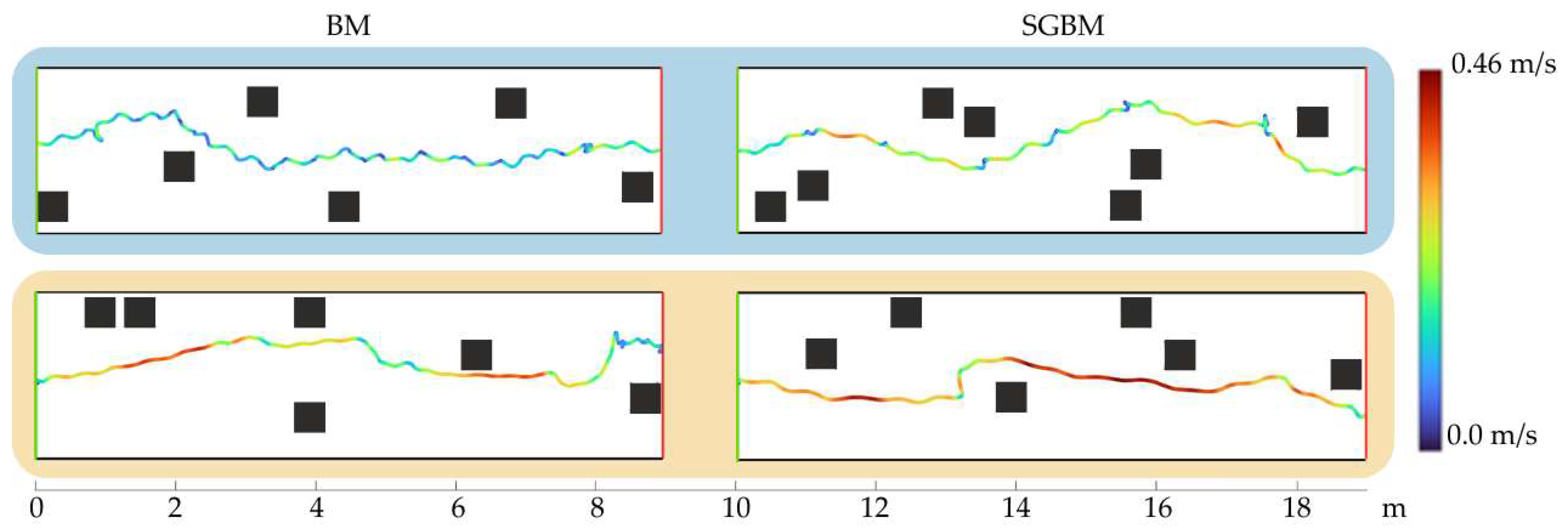
Walking speed is generally moderate and stable across conditions, with low inter-individual variability. As illustrated by the trajectories in
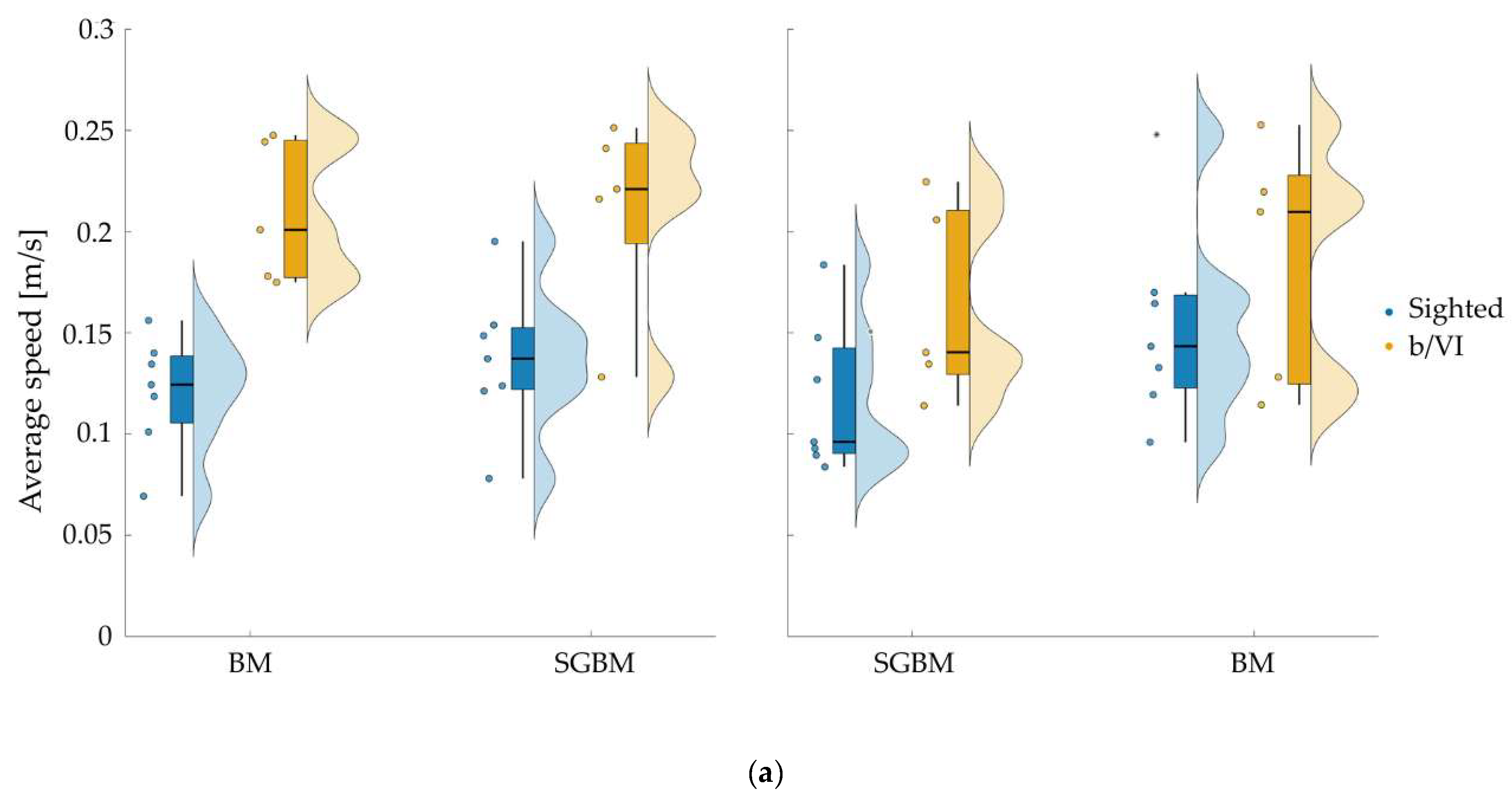
Figure 6, b/VI participants walk faster than sighted participants in all blocks: speed (mean ± SD) ranges from 0.12 ± 0.03 to 0.15 ± 0.05 m/s in the sighted group and from 0.16 ± 0.05 to 0.21 ± 0.05 m/s in the b/VI group (
Figure 7a), with overall averages of 0.13 ± 0.04 versus 0.19 ± 0.05 m/s (≈43% higher), and condition-wise differences ranging from about 20% to 75% in favor of the b/VI group.
Trajectory profiles are smooth and well controlled overall. In line with the patterns in
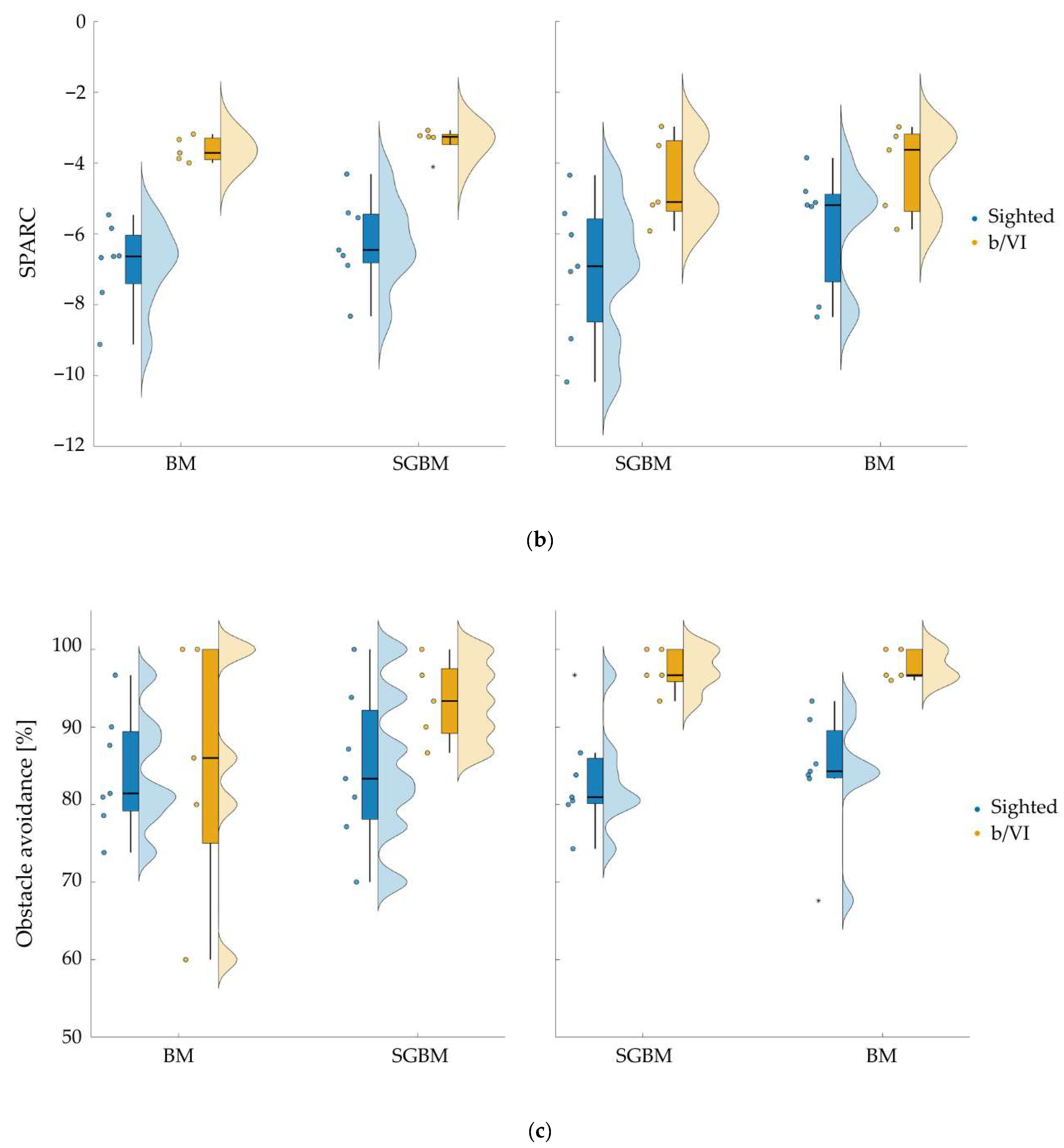
Figure 6, b/VI participants show more direct paths, with fewer slowdowns or hesitations when approaching obstacles. Blindfolded sighted participants tend to adopt a more stop-and-go pace. SPARC values vary from −4.53 ± 1.24 to −3.39 ± 0.41 in the b/VI group and from −6.99 ± 2.02 to −5.80 ± 1.72 in the sighted group (
Figure 7b).
Across sessions and groups, the mean obstacle-avoidance rate exceeds 80% (
Figure 7c), indicating a high level of safety and effective obstacle detection: sighted participants avoid on average 84.0% of obstacles (condition means ranging from 83.2 ± 7.0% to 84.6 ± 10.1%), whereas b/VI participants reach an average of 93.4% (from 85.2 ± 16.6% to 97.9 ± 2.0%). Among the 10 b/VI participants, ceiling-level performance is observed in six participant–algorithm combinations.
Taken together, these observations confirm that participants were able to interpret and use the vibrotactile feedback effectively from the outset, establishing the baseline functionality of the system before examining algorithmic, session-related, or group-dependent effects.
3.2. Computational Performance and Real-Time Operation
On the experimental hardware, both algorithms were integrated into a 30 Hz asynchronous acquisition-and-feedback pipeline, but with markedly different processing delays. Under the adopted multi-level parallelization strategy, BM required 20.21 ± 5.01 ms per frame, whereas SGBM required about 120.55 ± 47.77 ms per frame. These timings quantify the expected trade-off between a lighter local method and a smoother semi-global one: SGBM delivers denser and less noisy disparity maps at a substantially higher computational cost, while BM was associated with lower input-to-feedback latency. Behaviorally, however, this sixfold difference in per-frame processing time did not translate into measurable differences in obstacle avoidance, walking speed, or trajectory smoothness, as detailed in the following sections.
3.3. H1—Algorithmic Equivalence and Order Effects
The main effect of Algorithm (BM vs. SGBM) is not significant for any metric—obstacle avoidance: F(1,19) = 2.10,
p = 0.164, η
2 = 0.007; walking speed: F(1,19) = 4.35,
p = 0.051, η
2 = 0.004; SPARC: F(1,19) = 0.95,
p = 0.341, η
2 = 0.001—suggesting that both disparity-map algorithms support comparable levels of performance and therefore functional equivalence between methods (
Figure 7).
The Algorithm × Starting Algorithm interaction is significant for walking speed (F(1,19) = 15.77,
p < 0.001, η
2 = 0.013) and trajectory smoothness (SPARC) (F(1,19) = 15.70,
p < 0.001, η
2 = 0.011). Post hoc analyses show that BM yields the highest speed and smoother trajectories when administered in the second session (walking speed:
p < 0.001; SPARC:
p = 0.002,
Figure 7b,c), whereas SGBM does not differ significantly between first and second sessions (walking speed:
p = 0.073; SPARC:
p = 0.134). Thus, the order-related improvement is specific to BM, consistent with a benefit from prior exposure to the device/feedback rather than an intrinsic algorithmic advantage. Importantly, obstacle-avoidance remains high and unaffected by order (no significant effects involving Algorithm; all
p > 0.13,
Figure 7c).
No other interactions involving Algorithm (e.g., Algorithm × Vision, Algorithm × Trial, or Algorithm × Age) reach significance (all p > 0.10), indicating that the pattern of algorithmic equivalence is consistent across groups, sessions, and trials.
Overall, both BM and SGBM support comparable levels of functional performance, suggesting that, in this context, algorithm selection can be guided primarily by computational efficiency or energy-consumption criteria rather than behavioral outcomes.
3.4. H2—Learning and Familiarization Independent of the Algorithm
Performance remains generally stable across the five consecutive trials performed with the same algorithm, showing no systematic within-session learning. The Trial main effect is not significant (all p > 0.15), indicating that participants achieve consistent performance from the first block onward.
For obstacle avoidance (
Figure 7c), neither the main effect of Algorithm nor the Algorithm × Starting Algorithm interaction reaches significance (F(1,19) = 1.36,
p = 0.258), confirming that safety remains consistently high across sessions and is unaffected by order or algorithmic differences.
Together, these results support H2: participants show rapid familiarization with the vibrotactile system, leading to improved speed and smoothness with practice but without algorithm-specific learning effects.
3.5. H3—Group Robustness
Across all performance metrics, a clear main effect of Vision status is observed, confirming that b/VI participants outperform blindfolded sighted participants (
Figure 7). b/VI users avoid more obstacles (F(1,19) = 7.28,
p = 0.014, η
2 = 0.049), walk faster (F(1,19) = 7.86,
p = 0.011, η
2 = 0.083), and produce smoother trajectories (F(1,19) = 14.94,
p = 0.001, η
2 = 0.141). These differences are consistent with the greater expertise of b/VI participants in non-visual navigation and their ability to efficiently integrate vibrotactile feedback into movement control.
No significant interactions involving Vision status with Algorithm or Starting Algorithm are observed (all p > 0.10), indicating that the superiority of b/VI participants is independent of the disparity method and unaffected by session order. As explained in H2, both groups benefit similarly from between-session familiarization, suggesting that the system supports effective adaptation regardless of visual experience.
Although the two groups differ in mean age, the covariate Age shows no significant main or interaction effects in any model, suggesting that age did not provide additional explanatory power beyond the main group comparison in the present dataset.
Overall, these findings confirm H3: the system performs robustly across user populations, with visually impaired participants showing expected advantages in speed, safety, and movement smoothness. This reflects their greater experience with non-visual navigation rather than algorithm-specific advantages. Crucially, these group differences are consistent across algorithms and sessions, underscoring the generalizability and reliability of the system’s usability across diverse user profiles.
3.6. Exploratory Association Between Walking Speed and Obstacle Avoidance
To assess whether faster walking was associated with reduced obstacle avoidance, participant-level mean walking speed and mean obstacle-avoidance rate were correlated separately within each group. No significant correlation emerged in the blindfolded sighted group (r = −0.216, p = 0.459). In contrast, the b/VI group showed a significant, modest negative correlation (r = −0.644, p = 0.045), suggesting that participants who walked faster tended to avoid slightly fewer obstacles. Given the small subgroup sizes and the bounded, near-ceiling nature of obstacle-avoidance values, these findings should be interpreted as exploratory.
4. Discussion
This work evaluates a complete sensing-and-feedback architecture for non-visual navigation guidance. The device combines a passive stereo camera, visual SLAM, and region-based vibrotactile cues to deliver timely and spatially meaningful guidance using wearable sensing and feedback supported by external commodity hardware. In our implementation, stereo image processing runs on an off-the-shelf laptop that communicates wirelessly with a Raspberry Pi responsible for networking and vibrotactile actuator control; all modules execute on generic CPU-only hardware without dedicated accelerators. Across all performance indices (obstacle avoidance, walking speed, and trajectory smoothness), participants navigated safely and consistently, with stable performance across repetitions and minimal familiarization. Critically, no statistically significant differences were observed between Block Matching and Semi-Global Block Matching at user-level performance. These results indicate that the system can support real-time indoor navigation guidance using non-specialized, low-cost hardware.
To place the proposed system in context,
Table 2 compares it with representative existing electronic travel aids that address similar obstacle-detection or navigation-support functions.
Within this context, the present design addresses three recurring gaps in the literature: (i) the under-representation of blind/VI participants in evaluation studies, (ii) the lack of standardized, user-centered outcomes beyond coarse completion or collision counts, and (iii) the scarcity of user-level evidence to guide stereo algorithm selection under real-time constraints. Taken together, the present study explicitly links algorithmic design choices to end-user performance, demonstrating that low-complexity stereo pipelines can provide sufficiently accurate information evaluated through navigation performance.
Earlier studies on wearable stereo systems [
16,
17,
18,
19,
20,
21] often struggled to achieve real-time performance, depended on prototype-specific processing architectures, or remained weakly validated at the user level. Our implementation also uses an external processor (a commodity laptop), but it remains entirely CPU-only based and built from generic, easily substitutable components. The comparable results obtained with BM and SGBM suggest that differences between the lighter local (BM) and the smoother semi-global approach do not translate into perceptible differences in navigation guidance for the user.
Compared with infrared RGB-D sensors, which are sensitive to bright sunlight, specular surfaces, or complex illumination, passive stereo is less constrained by ambient illumination, although it still depends on image quality and scene texture. It directly reconstructs scene geometry (free space, obstacles, ground plane) from synchronized image pairs [
43,
44]. When fused with visual SLAM, stereo provides metrically scaled localization, loop-closure–based relocalization, and reusable mapping. These capabilities are well established in autonomous navigation and have matured to real-time implementations on compact hardware [
45,
46,
47,
48,
49]. This approach avoids the fragility of structured-light/Time of Flight sensors to ambient light and the directional sparsity of single-beam sonars [
13,
14,
50]. A related point concerns the type of obstacles used in the experimental trials. The present detection pipeline is geometry-based rather than category-based: it relies on stereo-derived structure and corner-supported depth cues. This design makes the system potentially applicable to obstacles of different shapes, materials, or categories, provided that they generate sufficient visual structure in the stereo pair, although this generalization requires further empirical test.
In the context of classical stereo, OpenCV’s BM and SGBM occupy a pragmatic operating point for low-power wearables and portable systems. BM is purely local, deterministic, and memory-light, enabling low-latency disparity on modest CPUs; SGBM introduces path-wise smoothness to produce denser, typically more accurate depth at a moderate computational premium that remains feasible without GPUs/TPUs [
37,
51,
52]. In contrast, global optimization methods (e.g., graph cuts, belief propagation, dynamic-programming variants) can improve accuracy but substantially increase compute and memory demands, thereby limiting real-time use on embedded platforms [
53,
54,
55,
56]. Deep stereo has been shown to achieve state-of-the-art accuracy, particularly in textureless or reflective regions. However, it typically requires large models, hardware accelerators, and strict power and latency budgets, with many networks barely reaching real time even on embedded GPUs [
57,
58,
59]. Against this technological backdrop, the observed behavioral equivalence supports the continued use of classical stereo methods as CPU-only baselines for low-cost assistive devices.
The observed group differences aligned with the expected patterns: visually impaired participants tended to avoid more obstacles and walk at a faster pace and more smoothly than blindfolded sighted controls. These offsets are consistent with long-term sensorimotor adaptation to non-visual exploration and better integration of tactile and proprioceptive cues, rather than algorithmic effects. This finding is consistent with the absence of significant Algorithm × Group interaction and with prior critiques that evaluation protocols often under-specify user-centered endpoints [
23,
24,
25]. Crucially, high avoidance rates (>80% on average, approaching 100% for some visually impaired participants) and stable smoothness indicate that the vibrotactile encoding was both intuitive and sufficient to maintain safety without visual cues. The outcomes of the study align with our hypotheses: functional equivalence between methods (H1); no algorithm-specific learning effects (H2); and robust group differences without algorithm-specific interactions (H3).
Average walking speeds in the present study were markedly lower than typical free-walking values reported for both sighted adults and blind or visually impaired pedestrians [
60,
61,
62]. This reduction likely reflects the cautious strategy adopted in a cluttered environment while participants were learning to interpret an unfamiliar vibrotactile feedback channel, rather than a simple ceiling imposed by algorithm choice. Exploratory within-group correlations did not indicate a general speed–safety trade-off: no significant association was found in blindfolded sighted participants, whereas the b/VI group showed a modest negative correlation between walking speed and obstacle avoidance. Because this latter result is based on a small subgroup and obstacle avoidance approached a ceiling in several visually impaired participants, it should be interpreted cautiously and verified in larger cohorts.
The composition of the b/VI group should be considered when interpreting the present findings. Only one participant retained residual vision, and this participant was blindfolded during testing to standardize the task to vibrotactile cues as the only source of spatial information; the present results therefore reflect system use under complete visual deprivation rather than under visual–vibrotactile augmentation. In addition, the b/VI group was heterogeneous with respect to blindness onset and duration. This increases the practical relevance of the sample, but the study was not designed or powered to determine whether these participant characteristics modulated performance. Future studies with larger and more stratified cohorts should address this question directly.
Given that BM and SGBM demonstrate non-different user-level performance, implementers can choose on engineering grounds. In applications where responsiveness is critical, such as in embedded or battery-powered devices, BM may be a more suitable solution. Conversely, when denser depth maps are needed and computational resources are less constrained, SGBM remains a valuable option. This interchangeability facilitates system portability across hardware tiers, ranging from minimal CPU-only setups to more capable mobile processors, without compromising usability. More broadly, these results support the view that passive stereo and SLAM can serve as a foundation for assistive navigation devices, integrating human-centered constraints (e.g., comfort, power, portability) with comprehensive scene understanding.
Some limitations should be considered. The sample size limits the generalizability of the results, and the groups differ in mean age. Although this age difference was not statistically significant, it can not be fully disentangled from group effects in this dataset. Future studies should therefore prioritize age-matched recruitment to allow stronger inference on group-specific effects.
Testing was restricted to controlled indoor environments with a limited subset of the obstacle shapes, heights, and surface properties. While the geometry-based pipeline is expected to generalize, some obstacle categories may remain challenging. In particular, low-lying objects such as curbs or steps are not currently recognized in terms of height or traversability, and transparent, reflective, or low-texture surfaces may generate weak or unstable disparity estimates. Broader testing with more diverse obstacles will therefore be necessary to define the operational boundaries of the system more completely.
Real-world deployment factors also require further investigation. In the present study, the vibrotactile actuators were applied directly to the skin to minimize attenuation. However, clothing could attenuate the vibration cues’ intensity and interpretability. Future designs should therefore consider integrated wearable solutions, for example, garments or belts that preserve stable skin coupling.
Anthropometry variability was not assessed in the present study. A fixed hip-mounted camera configuration was used across participants, and their height may affect viewing geometry and detection performance. Although the system was effectively usable by all the participants, this aspect should be explicitly evaluated, investigating the system performance across a representative range of user heights and mounting configurations.
A key practical limitation concerns portability. The current system relies on an external laptop for the image process, meaning that the system is not fully wearable. A direct replacement of the laptop with a smartphone is not straightforward due to computational constraints [
63,
64,
65,
66]. Two possible development paths are: (i) replacing the laptop with an on-body embedded computing board, (ii) offloading computation to a remote service via smartphone or another mobile device. The latter option better aligns with the low-cost philosophy of the system, but it introduces additional challenges related to latency, jitter, connectivity, and data privacy. Long-term miniaturization of assistive wearables may also benefit from advances in skin-integrated and flexible haptic electronics, which could improve unobtrusiveness and user acceptance [
67]. This route was not pursued in the present study because it is not aligned with the current off-the-shelf, low-cost design philosophy. In addition, comfort and long-term wearability were not formally assessed in this study and should be systematically evaluated in future iterations, especially once the system is implemented in a fully portable architecture.
Next steps should expand the cohort size to increase statistical power and include age-balanced subgroups to sharpen group-level inferences. Evaluation should be extended to more naturalistic settings (e.g., outdoor, cluttered, dynamic environments) to test its robustness. In parallel, systematic profiling of latency and power across embedded and distributed architectures will be essential to identify viable pathways toward fully wearable implementations without degrading guidance quality.




 ,
,