Dynamic Wireless Power Transfer System Without Receiving Coil Position Detection Sensors



Abstract
1. Introduction
2. Materials and Methods
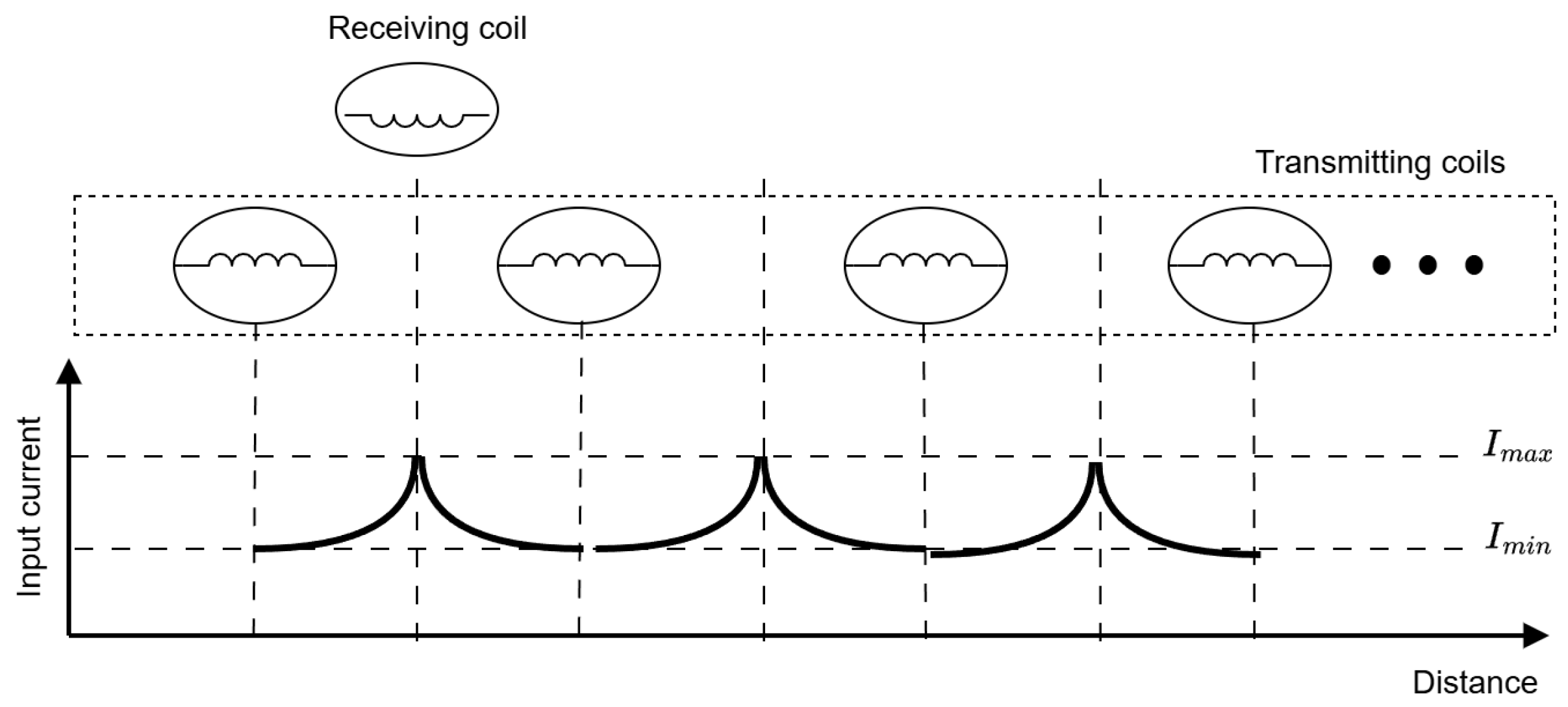
2.1. Description of the Proposed Method for Detecting the Position of the Receiving Coil
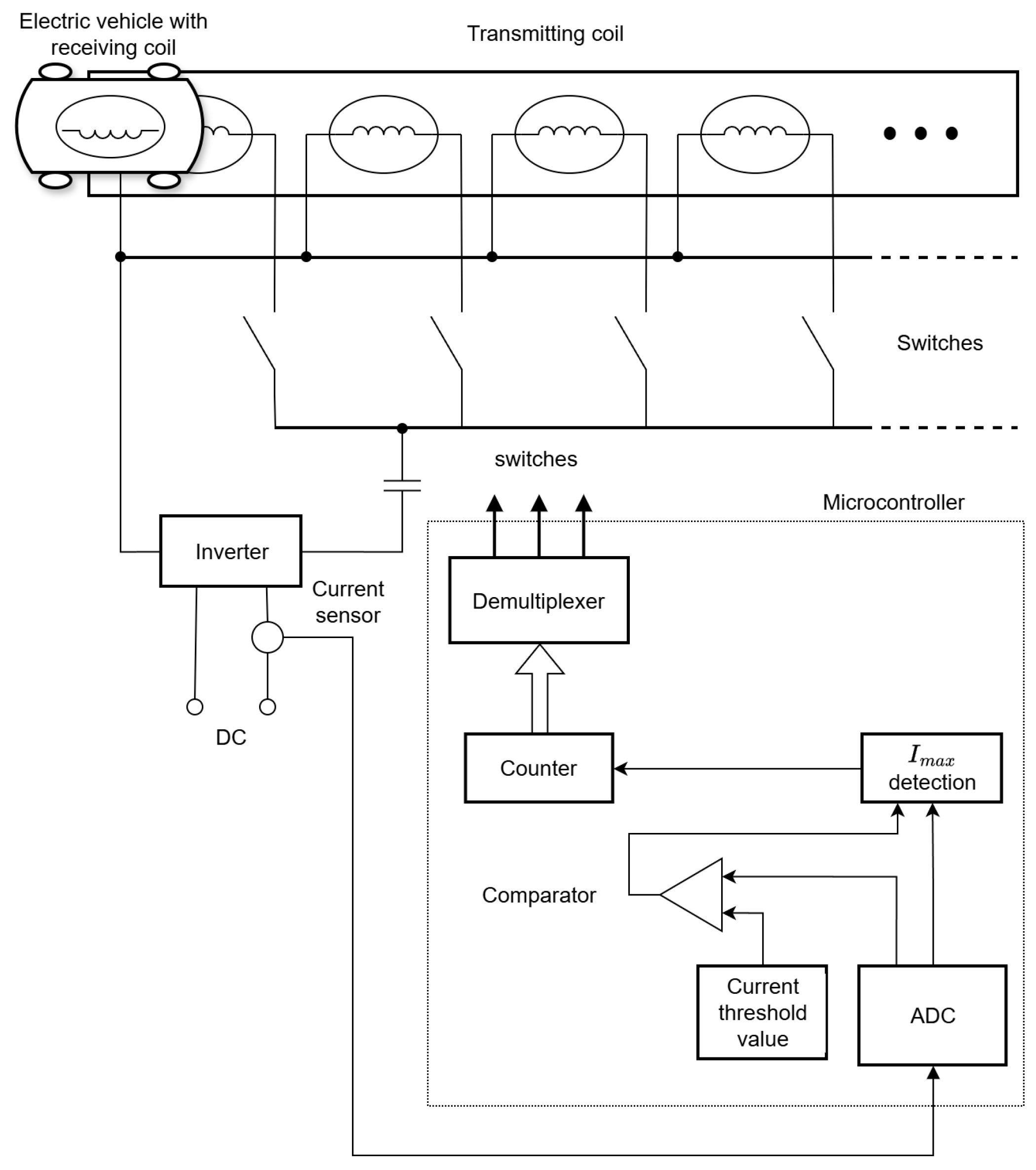
- The MC samples current values from the current sensor and converts them with the ADC;
- Value is compared against a predefined threshold value and simultaneously passed through the Imax detection block;
- If both conditions are met, a counter is incremented, and the demultiplexer switches the currently energized transmitting coil and energizes the subsequent one. This ensures a continuous energy supply to the receiving coil and, consequently, the electric vehicle.
- Cost-effectiveness: The system requires no complex structural modifications, only the addition of a current sensor and microcontroller. In contrast, solutions in [8,9,10,11,12] require multiple sensors, while sensorless alternatives such as [13] require multiple inverters. Furthermore, unlike [7], this method avoids the complexities of variable frequency control, thereby minimizing implementation costs;
- Design simplicity and robustness: The method is noticeably simpler and offers a robust and efficient solution for receiving-coil detection and transmitting coils switching.
- Algorithm requirement: The effectiveness of the system relies on the development of a precise control algorithm for the timely detection of the receiving coil and correctly switching transmitting coils;
- Efficiency trade-off: The efficiency may be limited due to the inherent nature of the method, as the resonant tuning is not performed at the position of maximum coupling between the transmitting and receiving coils;
- Initial coil-position detection challenge: While the primary scope of this study is to validate the switching logic of the proposed method, initial detection of the receiving-coil position remains a challenge.
2.2. Development of Experimental Prototype
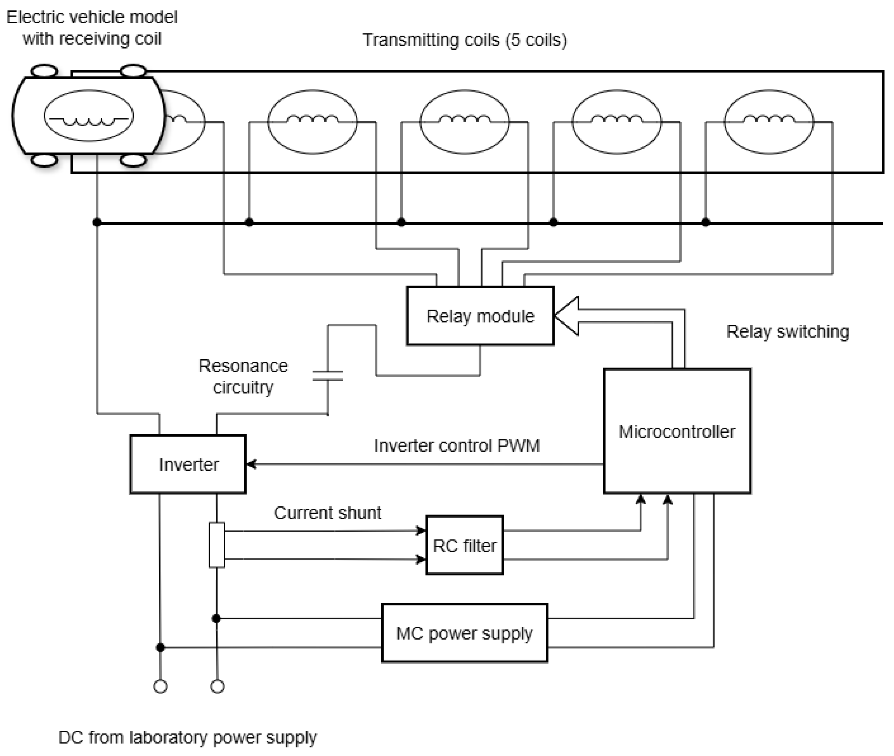
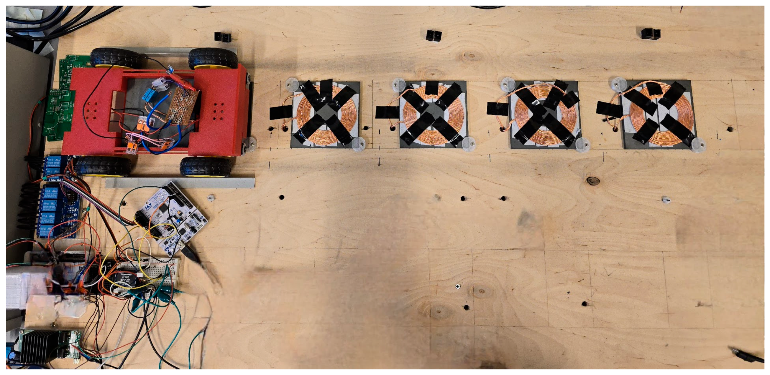
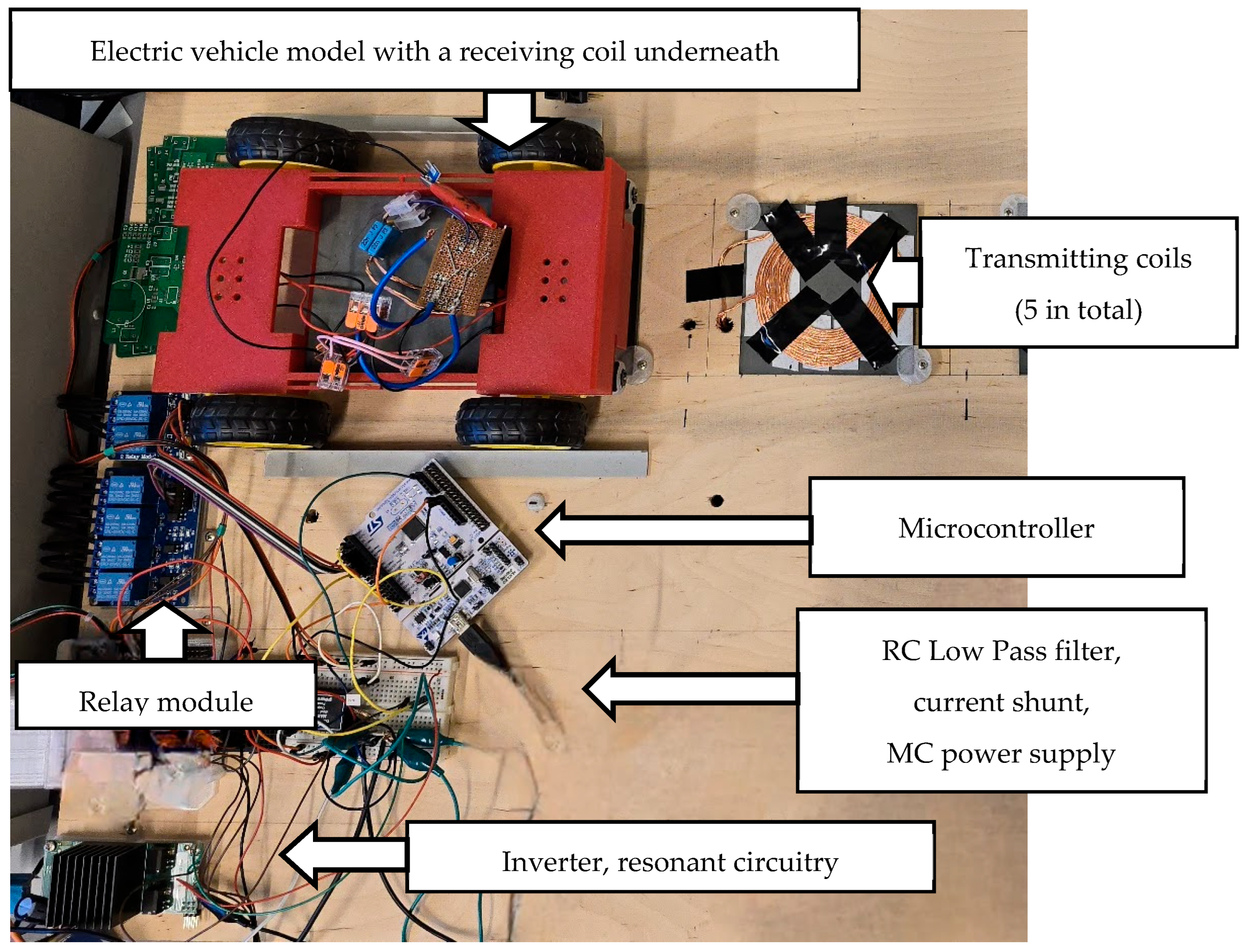
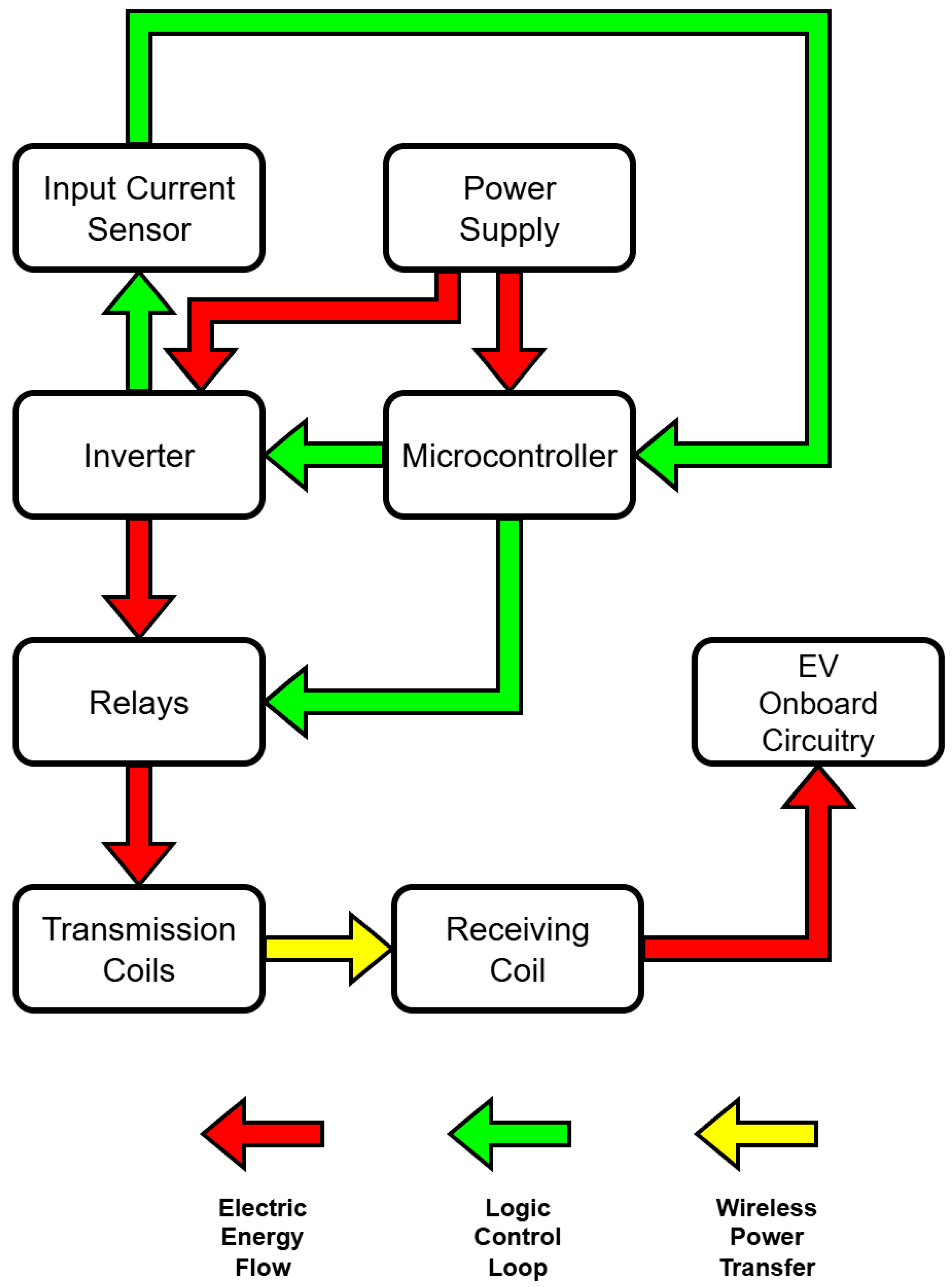
- A laboratory power supply (0 to 60 V DC);
- A 5 V DC power supply for the microcontroller;
- An inverter with resonance circuitry with a 0.1 Ω shunt resistor for input current sampling;
- A relay module for switching between the five transmitting coils;
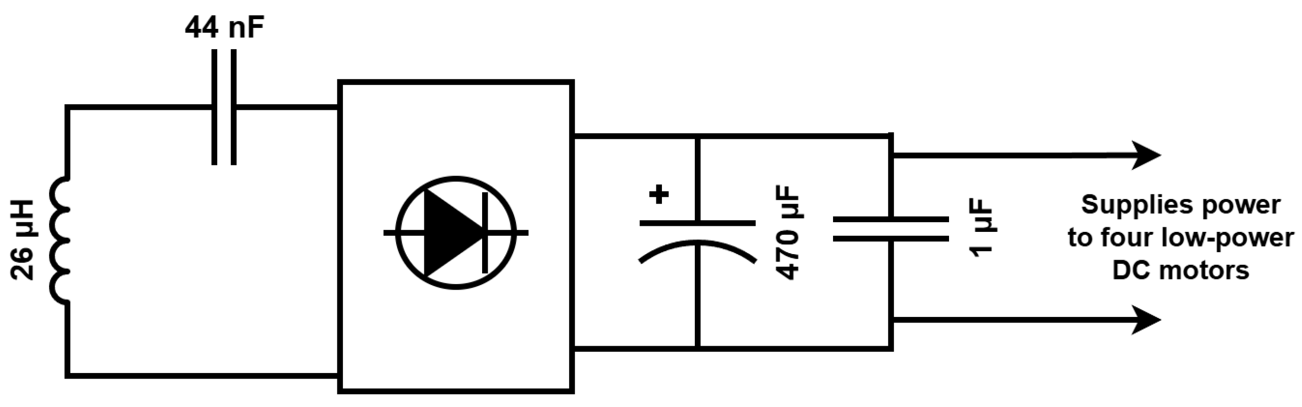
- An electric vehicle model with a bottom-mounted receiving coil, resonance circuitry, a full bridge rectifier, and four low-power DC motors. A simplified schematic of onboard electronics and connections is provided in Figure 5.
- An STM32 Nucleo-64 STM32F401RE development board;
- A low-pass RC filter connected between the microcontroller’s analog input and the shunt resistor.
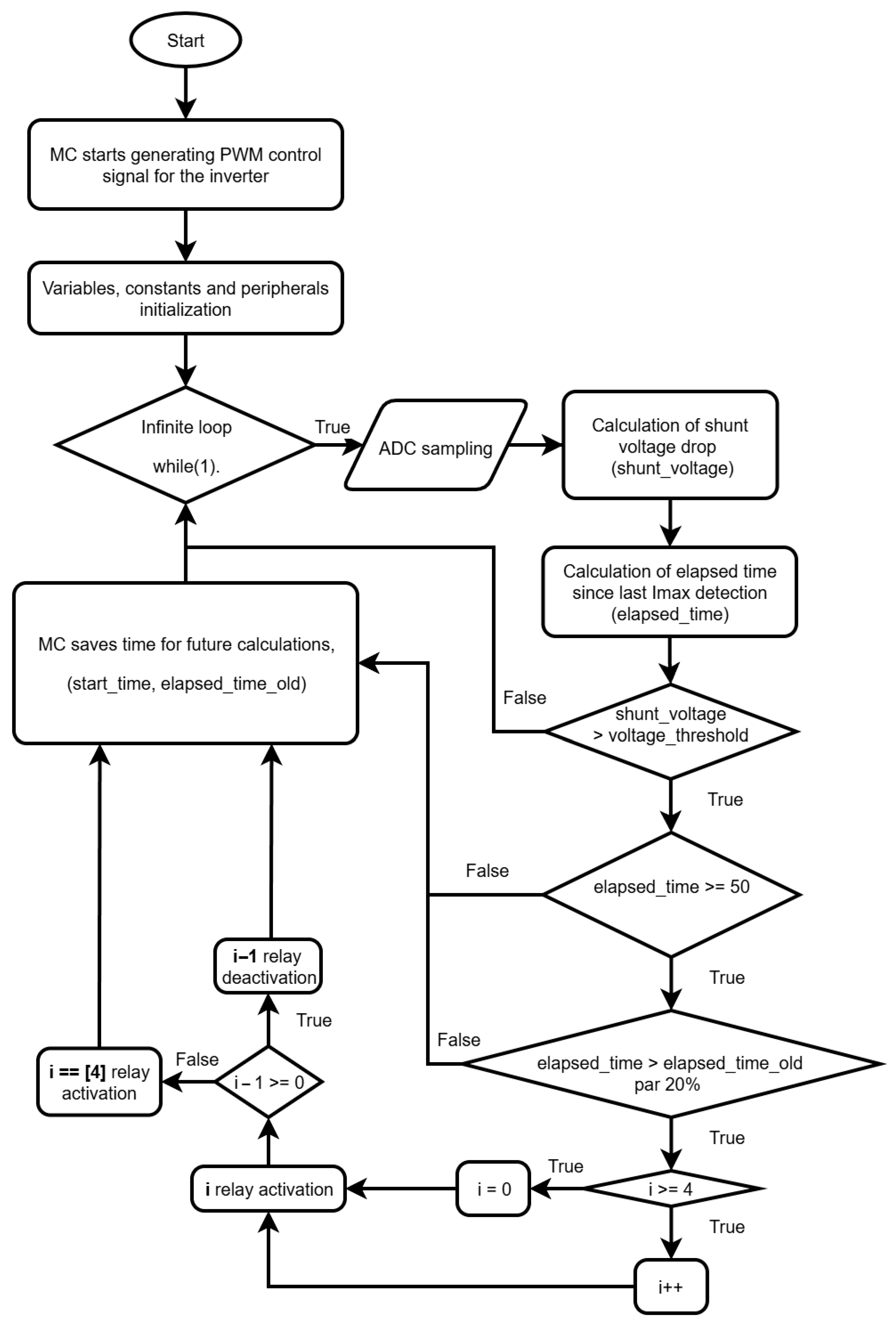
- Generation of PWM control signal for the inverter;
- Imax detection and transmitting coil switching with a relay module.
2.3. New Method Implementation with Microcontroller’s Algorithm and Program
- At least one ADC and an analog input;
- Programmable digital outputs;
- A programmable hardware timer capable of generating PWM and inverted PWM signals with dead-time setting;
- Comprehensive manufacturer and community support, documentation.
- i—an integer variable that acts as a counter and stores the index of the currently energized coil from 0 to 4, representing the five transmitting coils, respectively;
- voltage_threshold—a floating-point constant that stores the voltage threshold value for the current spike Imax;
- shunt_voltage—a floating-point variable that stores the current shunt voltage drop calculated from the ADC values;
- elapsed_time, elapsed_time_old, start_time—variables used to calculate the duration between two occurred Imax detections.
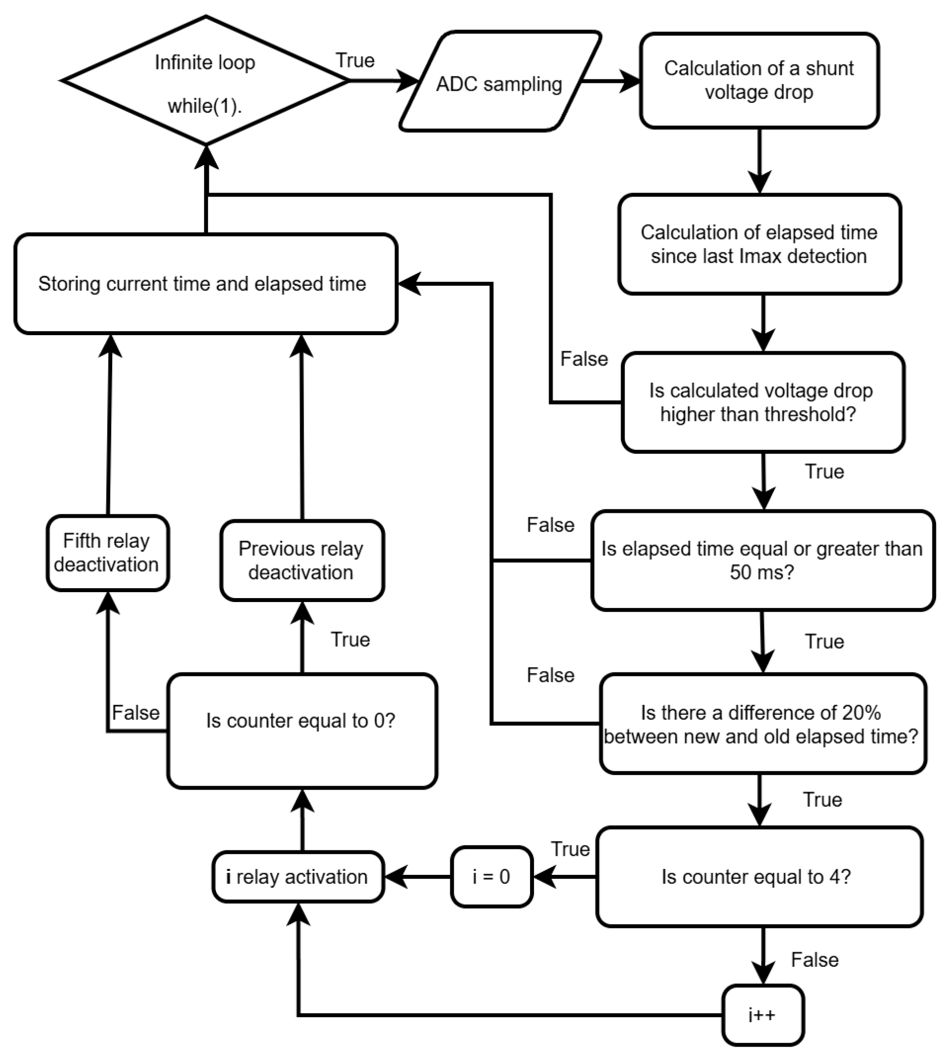
- Voltage threshold—if the shunt voltage exceeds the threshold value, then the Imax current spike at the inverter input has been reached;
- Duration between two detections—the elapsed time between two subsequent Imax detections. If the calculated duration is below a predetermined threshold, the detection is ignored to prevent false switching.

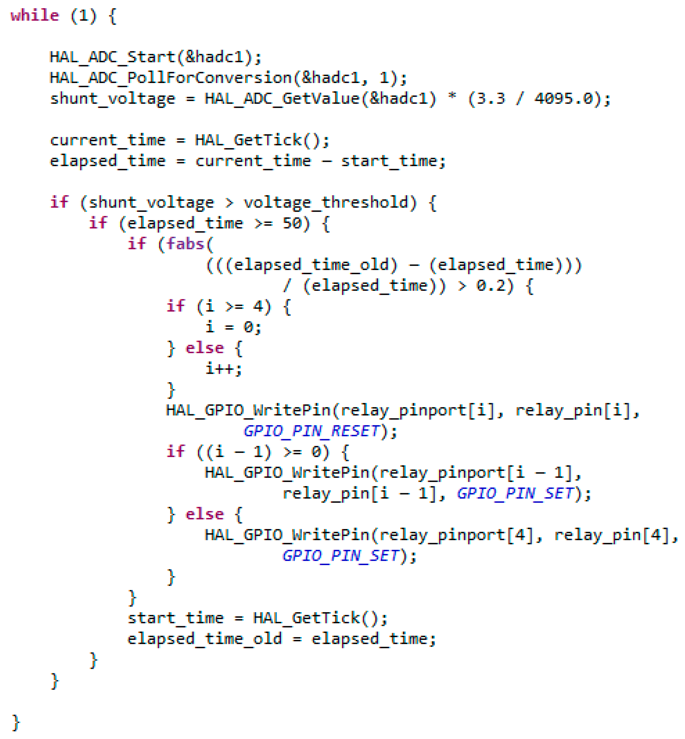
2.4. Microcontroller Current Spike Imax Detection and Transmitting Coil Switching Code
2.5. Experimental Testing Plan
- The electric vehicle model was placed at the starting position on the first transmitting coil for each trial;
- Four synchronized waveforms were recorded using a single 4-channel oscilloscope: input voltage and current of the inverter, and the output voltage and current from the onboard rectifier;
- To achieve the target speeds of the electric vehicle model, the laboratory power supply voltage was adjusted accordingly.
3. Results
3.1. First Experiment
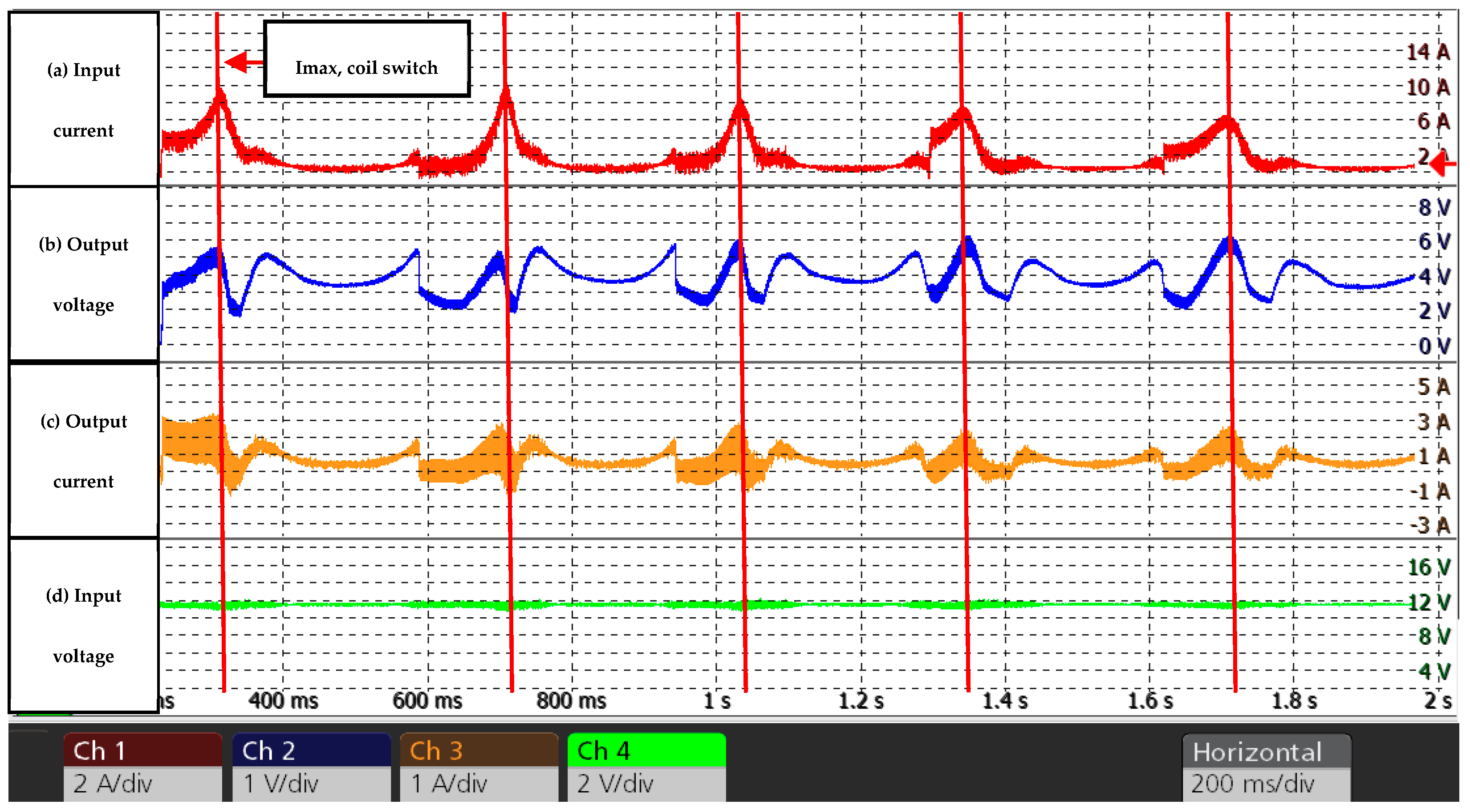
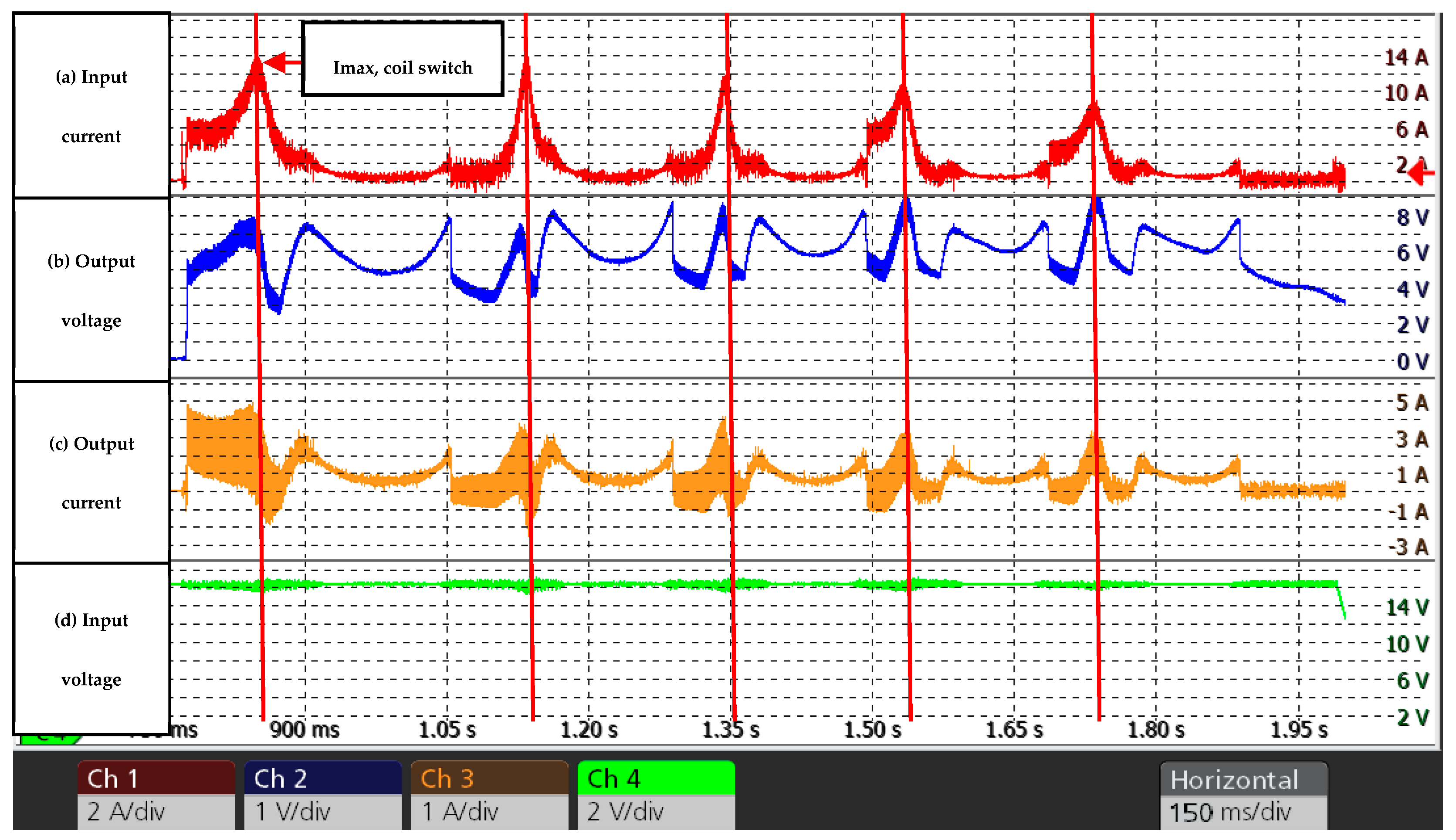
- (a)
- Inverter input current;
- (b)
- Rectifier output voltage on the electric vehicle;
- (c)
- Rectifier output current on the electric vehicle;
- (d)
- Inverter input voltage—while this remained largely constant, its waveform was recorded to simplify the data processing.

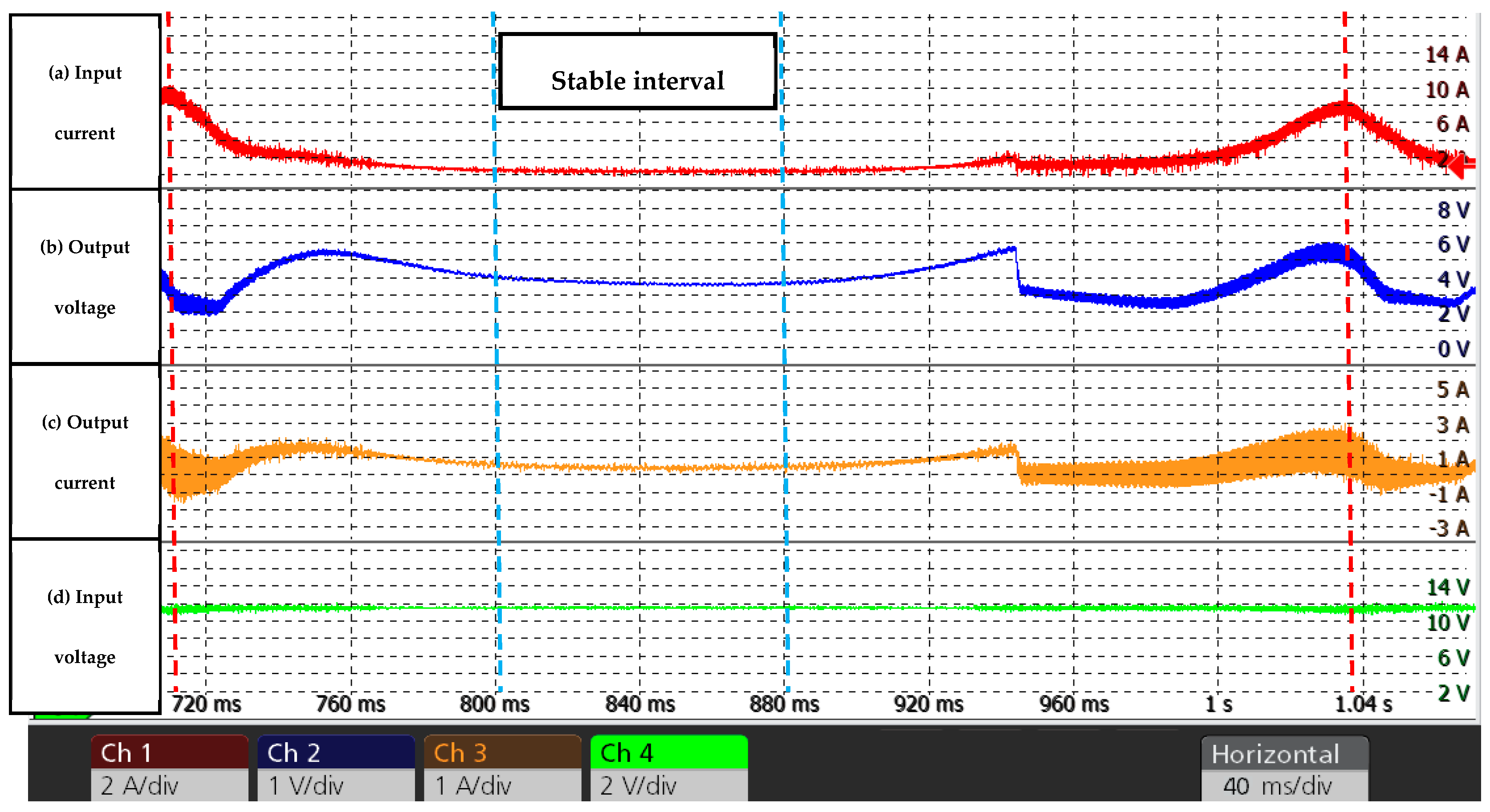
- Peak-to-Peak efficiency was calculated as the ratio of average output power (≈2.8 W) to average input power (≈18 W) during the period between current peaks (indicated by red vertical dotted lines in Figure 12). This coefficient was ≈ 15.5%.
- Stable interval efficiency was calculated as the ratio of average output power (≈1.5 W) to average input power (≈3.2 W) during the period in a stable time interval, indicated by blue vertical dotted lines in Figure 12. This coefficient was ≈ 46.8%.
3.2. Second Experiment
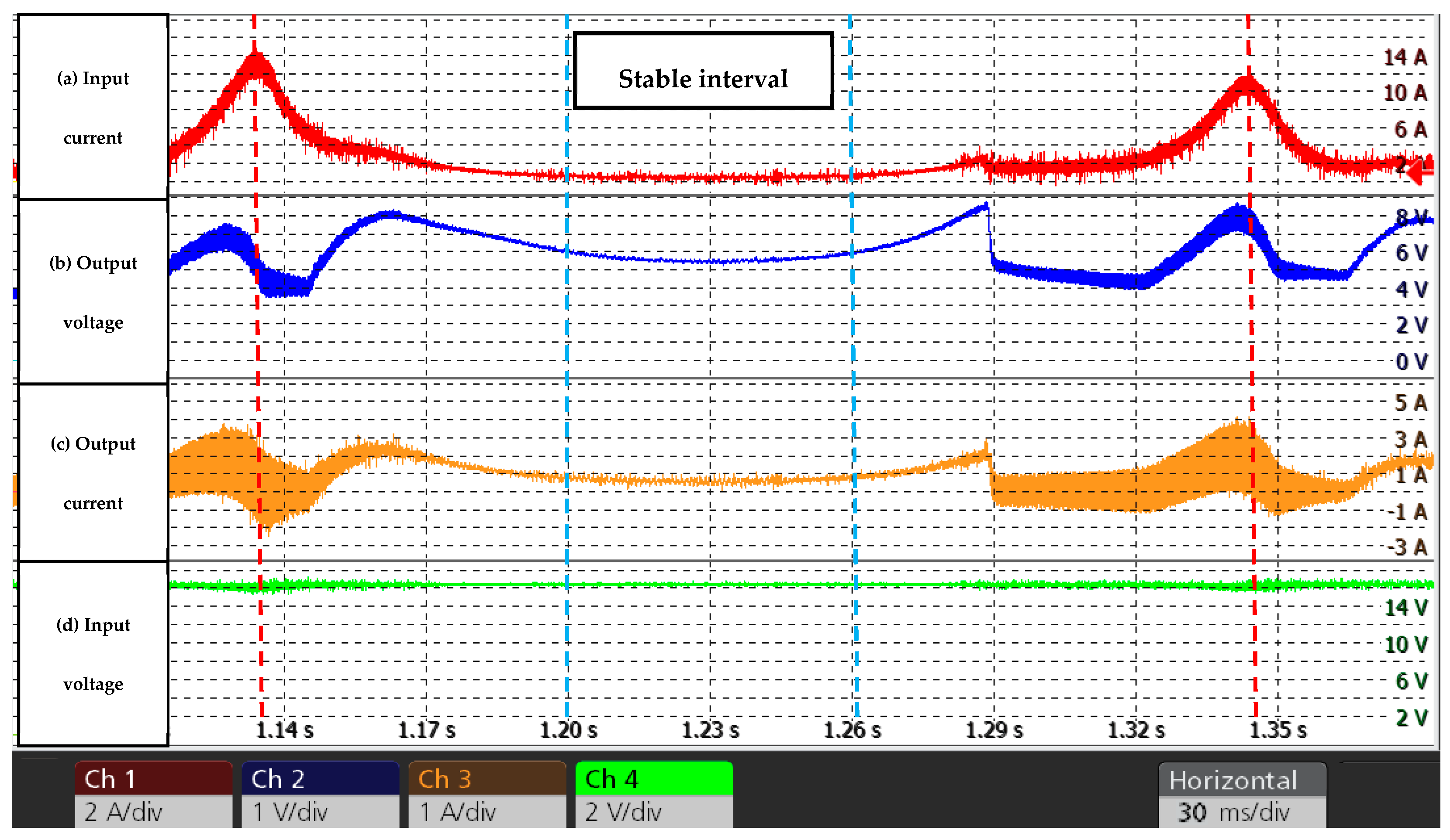
- Peak-to-Peak efficiency coefficient was ≈ 17.4%.
- Stable interval efficiency coefficient was ≈ 53.2%.
4. Discussion
- Sequential excitation: Since the microcontroller regulates which transmitting coil is energized at any given time, the system can sequentially energize each coil while monitoring current variations;
- Current regulation: By modulating the inverter’s switching frequency and PWM signal duty cycle, the microcontroller can restrict the current to a level sufficient for detection but below the threshold required to drive the EV motors, ensuring the vehicle remains stationary during the scan;
- Pattern recognition: A detection algorithm must be developed to recognize current changes;
- Position detection: By “scanning” all the transmitting coils, the specific coil coupled with the receiving coil can be determined to establish the initial position.
- Improving the electrical part of the test bench (e.g., securing connections, minimizing parasitic capacitances, and inductances);
- Investigating the test bench and system for other potential issues that affect efficiency;
- Exploring methods for determining the starting position of the receiving coil with and without additional sensors;
- Improving the software (code) to simplify experimental trials.
5. Conclusions
Author Contributions
Funding
Data Availability Statement
Conflicts of Interest
References
- Mejri, E.; Kelouwani, S.; Dube, Y.; Henao, N.; Agbossou, K. Energy Efficient Order Picking Routing for a Pick Support Automated Guided Vehicle (Ps-AGV). IEEE Access 2022, 10, 108832–108847. [Google Scholar] [CrossRef] [Scilit]
- Majid, S.A.A.; Zakaria, W.N.W.; Patar, M.N.A.A.; Tomari, M.R.M.; Amari, M.D.; Kasran, F.A.M. Optimized Global Path Planning with SLAM for Efficient Warehouse Autonomous Mobile Robot. In Proceedings of the 2025 IEEE 6th International Conference in Robotics and Manufacturing Automation (ROMA), Selangor, Malaysia, 20–22 August 2025; Institute of Electrical and Electronics Engineers Inc.: New York, NY, USA, 2025; pp. 377–381. [Google Scholar]
- Shinohara, N. Wireless Power Transfer via Radiowaves; ISTE-Wiley: Hoboken, NJ, USA, 2014; ISBN 9781118862964. [Google Scholar]
- Chen, W.; Han, X.; Pan, Y.; Yuan, Y.; Kong, X.; Liu, L.; Sun, Y.; Shen, W.; Xiong, R. Defects in Lithium-Ion Batteries: From Origins to Safety Risks. Green Energy Intell. Transp. 2025, 4, 100235. [Google Scholar] [CrossRef] [Scilit]
- McNulty, D.; Hennessy, A.; Li, M.; Armstrong, E.; Ryan, K.M. A Review of Li-Ion Batteries for Autonomous Mobile Robots: Perspectives and Outlook for the Future. J. Power Sources 2022, 545, 231943. [Google Scholar] [CrossRef] [Scilit]
- Patil, D.; Miller, J.M.; Fahimi, B.; Balsara, P.T.; Galigekere, V. A Coil Detection System for Dynamic Wireless Charging of Electric Vehicle. IEEE Trans. Transp. Electrif. 2019, 5, 988–1003. [Google Scholar] [CrossRef] [Scilit]
- Pakhaliuk, B.; Husev, O.; Shevchenko, V.; Kroics, K.; Stepins, D.; Strzelecki, R. Automatic Position Detection and Transmitting Activation of Dynamic Wireless Power Transfer System with Air Capacitor. In Proceedings of the 2022 Wireless Power Week (WPW), Bordeaux, France, 5–8 July 2022; IEEE: Hoboken, NJ, USA, 2022; pp. 487–491. [Google Scholar]
- Liang, C.; Zhang, Y.; Li, Z.; Yuan, F.; Yang, G.; Song, K. Coil Positioning for Wireless Power Transfer System of Automatic Guided Vehicle Based on Magnetic Sensing. Sensors 2020, 20, 5304. [Google Scholar] [CrossRef] [Scilit] [PubMed]
- Jeebklum, P.; Kirawanich, P.; Sumpavakup, C. Dynamic Wireless Power Transfer with a Resonant Frequency for Light Duty Electric Vehicle. Int. J. Intell. Eng. Syst. 2021, 14, 417–426. [Google Scholar] [CrossRef] [Scilit]
- Thalapil Vaheeda, J.; George, B. TMR Sensor-Based Detection of EVs in Semi-Dynamic Traffic for Optimal Charging. IEEE Trans. Intell. Transp. Syst. 2022, 23, 13721–13730. [Google Scholar] [CrossRef] [Scilit]
- Stepins, D.; Zakis, J.; Sokolovs, A.; Husev, O.; Strzelecki, R.; Doncker, R.W. de Dynamic Wireless Power Transfer System for Indoor AGV With a Distance-Measurement-Based Position Detection Technique. IEEE Access 2025, 13, 71551–71562. [Google Scholar] [CrossRef] [Scilit]
- Stepins, D.; Sokolovs, A.; Zakis, J. Dynamic Resonant-Inductive Wireless Power Transfer System for Automated Guided Vehicles with Reduced Number of Position Sensors. Electronics 2024, 13, 2377. [Google Scholar] [CrossRef] [Scilit]
- Xiong, W.; Liu, J.; Chen, J.; Hu, D. Detection of Secondary Side Position for Segmented Dynamic Wireless Charging Systems Based on Primary Phase Angle Sensing. Electronics 2023, 12, 2148. [Google Scholar] [CrossRef] [Scilit]
- Matsumoto, H.; Noborikawa, R.; Zaitsu, T.; Shibako, Y. Wireless Power Transfer System With Passive Boost Topology for AGVs. IEEE Open J. Ind. Appl. 2020, 1, 227–235. [Google Scholar] [CrossRef] [Scilit]
- Lammle, T.; Parspour, N.; Holz, J. Comparison of Circular and Double-D Coil Topologies for Automotive Inductive Charging Systems. In Proceedings of the 2020 IEEE PELS Workshop on Emerging Technologies: Wireless Power Transfer (WoW), Seoul, Republic of Korea, 15–19 November 2020; IEEE: Hoboken, NJ, USA, 2020; pp. 68–73. [Google Scholar]
- Mohammad, M.; Choi, S. Optimization of Ferrite Core to Reduce the Core Loss in Double-D Pad of Wireless Charging System for Electric Vehicles. In Proceedings of the 2018 IEEE Applied Power Electronics Conference and Exposition (APEC), San Antonio, TX, USA, 4–8 March 2018; IEEE: Hoboken, NJ, USA, 2018; pp. 1350–1356. [Google Scholar]
- Xiang, L.; Sun, Y.; Tang, C.; Dai, X.; Jiang, C. Design of Crossed DD Coil for Dynamic Wireless Charging of Electric Vehicles. In Proceedings of the 2017 IEEE PELS Workshop on Emerging Technologies: Wireless Power Transfer (WoW), Chongqing, China, 20–22 May 2017; IEEE: Hoboken, NJ, USA, 2017; pp. 1–5. [Google Scholar]
- ElGhanam, E.; Hassan, M.; Osman, A.; Kabalan, H. Design and Performance Analysis of Misalignment Tolerant Charging Coils for Wireless Electric Vehicle Charging Systems. World Electr. Veh. J. 2021, 12, 89. [Google Scholar] [CrossRef] [Scilit]





| Parameter | Value | Units |
|---|---|---|
| Inductance of transmitting/receiving coils | 26 | µH |
| Switching frequency of the inverter 1 | 149 | kHz |
| Input voltage of the inverter | 12–16 | VDC |
| Capacitance of transmitting/receiving compensation capacitors | 44 | nF |
| Vertical distance between the transmitting and the receiving coils’ ferrite pads | 25 | mm |
| Dimensions of the ferrite pad | 100 × 100 | mm |
| Distance between the centers of the transmitting coils | 160 | mm |
| Total number of transmitting coils | 5 |
Disclaimer/Publisher’s Note: The statements, opinions and data contained in all publications are solely those of the individual author(s) and contributor(s) and not of MDPI and/or the editor(s). MDPI and/or the editor(s) disclaim responsibility for any injury to people or property resulting from any ideas, methods, instructions or products referred to in the content. |
© 2026 by the authors. Licensee MDPI, Basel, Switzerland. This article is an open access article distributed under the terms and conditions of the Creative Commons Attribution (CC BY) license.
Share and Cite
Lapickis, D.; Stepins, D.; Zakis, J. Dynamic Wireless Power Transfer System Without Receiving Coil Position Detection Sensors. Electronics 2026, 15, 756. https://doi.org/10.3390/electronics15040756
Lapickis D, Stepins D, Zakis J. Dynamic Wireless Power Transfer System Without Receiving Coil Position Detection Sensors. Electronics. 2026; 15(4):756. https://doi.org/10.3390/electronics15040756
Chicago/Turabian StyleLapickis, Daniels, Deniss Stepins, and Janis Zakis. 2026. "Dynamic Wireless Power Transfer System Without Receiving Coil Position Detection Sensors" Electronics 15, no. 4: 756. https://doi.org/10.3390/electronics15040756
APA StyleLapickis, D., Stepins, D., & Zakis, J. (2026). Dynamic Wireless Power Transfer System Without Receiving Coil Position Detection Sensors. Electronics, 15(4), 756. https://doi.org/10.3390/electronics15040756