1. Introduction
In fields such as drones, robotics, and emergency response, real-time and precise position and orientation data are fundamental to intelligent navigation and collaborative operations. Currently, technologies capable of simultaneously achieving positioning and orientation estimation mainly include the following categories:
Multi-Antenna Global Navigation Satellite System (GNSS): This technology computes absolute position and orientation from the baseline vector formed by master and slave antennas. While it delivers high accuracy, it depends on reliable satellite signals and often fails in obstructed environments like indoors, urban canyons, tunnels, or dense foliage, leading to service interruptions [
1].
Visual Odometry (VO): VO estimates pose changes by analyzing consecutive image frames. It offers rich environmental texture and semantic information but is highly sensitive to lighting conditions and scene texture, with performance degrading significantly in low-texture or variable-light environments [
2].
Light Detection and Ranging (LiDAR) Odometry: This technology estimates motion trajectory and attitude by matching consecutive 3D point clouds. It provides high-precision 3D localization, is largely unaffected by lighting conditions, but suffers from high cost. Moreover, in feature-sparse environments such as long tunnels or open squares, point cloud matching becomes challenging, which can lead to localization failure [
3].
Millimeter-Wave Radar Odometry: Similarly based on consecutive point cloud matching, millimeter-wave radar exhibits superior robustness in adverse weather conditions (e.g., rain, fog, dust) compared to vision or LiDAR. However, its point clouds are sparser and generally yield lower accuracy and resolution [
4].
To enhance performance, these technologies are often integrated with an inertial navigation system (INS), which complements high-frequency attitude updates with absolute or relative positioning data. Nevertheless, such fusion increases system complexity and cost. Furthermore, if external sensors fail due to environmental factors, the INS-derived solution will accumulate integration errors, leading to unbounded drift in position and orientation.
The most advanced and resilient strategy today is multi-sensor fusion simultaneous localization and mapping (SLAM), which incorporates GNSS, cameras, LiDAR, and millimeter-wave radar within an integrated framework to exploit their complementary advantages. However, these systems are inherently complex, difficult to calibration, and costly. Consequently, they are primarily deployed in high-reliability scenarios and have not been widely adopted in time-sensitive applications like emergency response, where rapid deployment and scalability are critical.
Table 1 summarizes the characteristics of the above technologies, revealing a clear gap: a low-cost, low-complexity, all-weather solution that provides both positioning and orientation is still lacking.
Ultra-Wideband (UWB) technology has garnered significant interest for its centimeter-level ranging accuracy [
5]. However, a key limitation of most commercial UWB systems is their ability to estimate position but not orientation. To equip UWB with independent orientation estimation capabilities and eliminate reliance on supplementary sensors, researchers have explored extending single-antenna UWB into multi-antenna configurations. Current research primarily follows two paths:
Combining unsynchronized single-antenna modules: this category forms a system using multiple independent UWB modules without time synchronization. Position and orientation estimation relies on multiple sets of distance constraints. However, as each agent requires several modules, it necessitates extensive message exchange and increases device size [
6].
Employing synchronized single-antenna modules: This category also uses multiple modules but employs a shared clock and synchronization signal. Orientation is derived from phase difference measurements between modules. While effective, this category faces challenges of high system complexity, difficult hardware integration, and limited practicality for real-world deployment [
7].
Recently, commercial dual-antenna UWB modules (e.g., Qorvo DWM3220, Greensboro, NC, USA) have emerged, integrating time of flight (ToF) ranging and angle of arrival (AoA) measurement capabilities. This provides a hardware foundation for developing low-cost, integrated positioning and orientation systems [
8]. These modules obtain range measurements via single-sided or double-sided two-way ranging (SS-TWR/DS-TWR), eliminating the need for clock synchronization. A key innovation is the scrambled timestamp sequence (STS) field in the UWB packet, which enables precise time-offset measurement between the two antennas through software correlation, thereby replacing complex hardware synchronization. This time offset is converted into a phase difference, from which the AoA is calculated based on the wavelength and antenna spacing. Notably, AoA is obtained as a by-product of ranging without extra signal transmission.
However, the inherent linear array configuration of such modules introduces a front–back ambiguity issue [
9], which severely compromises orientation reliability. To the best of our knowledge, no published work has yet demonstrated a system capable of simultaneous positioning and orientation using only a single dual-antenna UWB module.
This paper presents a novel system that relies exclusively on a single dual-antenna UWB module to reliably estimate an agent’s position and orientation without fusing any additional sensors. Its main contributions are threefold:
First, recognizing that the accuracy of AoA measurements is generally inferior to that of ToF ranging in UWB systems, we adopt a “position-first, orientation-later” approch. The agent’s position is first estimated using an extended Kalman filter (EKF), and the orientation is subsequently derived based on this position estimate and the AoA measurements.
Second, we innovatively propose a method that integrates multi-hypothesis testing (MHT) with a circular likelihood metric (CLM) to effectively resolve the inherent front–back ambiguity of the linear dual-antenna array, thereby enabling accurate orientation determination. This constitutes a core contribution of our work.
Third, the entire system is designed to be self-contained, requiring only the dual-antenna UWB technology. It demonstrates strong robustness against variations in external conditions such as lighting, weather, and smoke, making it suitable for challenging environments.
The remainder of this paper is structured as follows:
Section 2 reviews the research on UWB-based positioning and orientation.
Section 3 introduces system model and the front–back ambiguity problem.
Section 4 details the two-stage positioning and orientation estimation approach.
Section 5 evaluates the system’s accuracy through Monte Carlo simulations under varying ranging and AoA noise conditions.
Section 6 validates the system’s performance via real-world experiments conducted on a precision rotary table, in an indoor field, and in an outdoor field. Finally,
Section 7 concludes the paper and suggests directions for future research.
2. Related Works
While Ultra-Wideband (UWB) positioning is a mature field, accurate orientation estimation remains a significant challenge. Existing solutions that extend UWB to determine orientation predominantly rely on one of three strategies, each introducing specific trade-offs in terms of system complexity, cost, or practicality. This section reviews these strategies—sensor fusion, multi-module configurations, and synchronized arrays—to highlight their limitations and contextualize our contribution.
2.1. Sensor Fusion with IMU
A prevalent strategy to obtain orientation is fusing UWB with an IMU. Studies like [
10,
11] exemplify this approach. Reference [
10] employs a loosely coupled EKF to fuse UWB, IMU, and barometer data, producing a full pose estimate. However, the orientation in such systems primarily relies on IMU state propagation, with UWB serving mainly to correct position drift. Similarly, ref. [
11] uses IMU data for the system state model and UWB as observations in a Kalman filter, where the orientation is independently derived from the IMU. Although integrating an IMU can theoretically improve dynamic performance and short-term accuracy, this enhancement is achieved at the expense of increased system complexity. Specifically, it necessitates expanding the state vector to include parameters for attitude, angular velocity, and accelerometer biases. This expansion, along with the added requirements for precise sensor calibration, time synchronization, and robust filter convergence, introduces significant design challenges.
2.2. Deployment of Multiple Single-Antenna Modules
Another strategy infers orientation by deploying multiple unsynchronized UWB modules to create geometric constraints. The work in [
6] is a notable example, achieving high-precision relative pose estimation by having multiple UWB antennas on each agent. However, this method requires mutual ranging between all antenna pairs on interacting agents. For instance, two agents with four modules each require 16 pairwise range measurements, leading to high system cost, large device size, and low spectrum efficiency. The study in [
12] similarly requires deploying multiple UWB modules on a vehicle, first solving for position and then estimating attitude. While [
13] incorporates orientation within an EKF, its measurements are still derived solely from UWB ranging between multiple nodes without direct orientation sensing, falling short of providing a definitive orientation solution.
2.3. Use of Phase-Synchronized Antenna Arrays
The most direct strategy for orientation is using phase-synchronized antenna arrays to measure the AoA. This category aims to derive orientation directly from incoming signals but faces significant hardware complexity. The study in [
7] employs a three-antenna array combining AoA and DS-TWR to jointly solve for position and orientation, yet it still faces challenges in hardware integration and practical deployment. Similarly, ref. [
14] proposes a cooperative system using a six-element UWB array, which requires precise phase synchronization and complex channel impulse response analysis, resulting in high implementation complexity. Although its theoretical framework supports orientation output, the original paper lacks an in-depth analysis of the achieved orientation accuracy. The same team’s later work [
15] further designed a four-antenna stereo array reported to achieve an azimuth error below 4.8°, and the work in [
16] integrates a three-antenna UWB array with an odometer, attaining a heading angle estimation accuracy of 3.4°. For a systematic survey of multi-antenna angle estimation research and a discussion of key trade-offs among different technologies, readers are referred to [
17].
2.4. Our System
In contrast, this work demonstrates that simultaneous positioning and orientation can be achieved using only a single, commercially available dual-antenna UWB module. Our system eliminates the need for IMU fusion, avoids the scalability issues of multi-module setups, and bypasses the hardware challenges of phase-synchronized arrays, offering a novel, low-cost, and highly practical alternative.
3. Models and Front–Back Ambiguity
Table 2 summarizes the mathematical notations used throughout this paper. This section formulates the system model for positioning and orientation using a dual-antenna UWB module and elaborates on the fundamental challenge of front–back ambiguity.
3.1. System Model
We consider a system comprising a mobile agent and stationary anchors. The agent’s state is defined as , where are its 2D coordinates and is its orientation. Each anchor is fixed at a known position and orientation, denoted by . All devices are equipped with a dual-antenna UWB module.
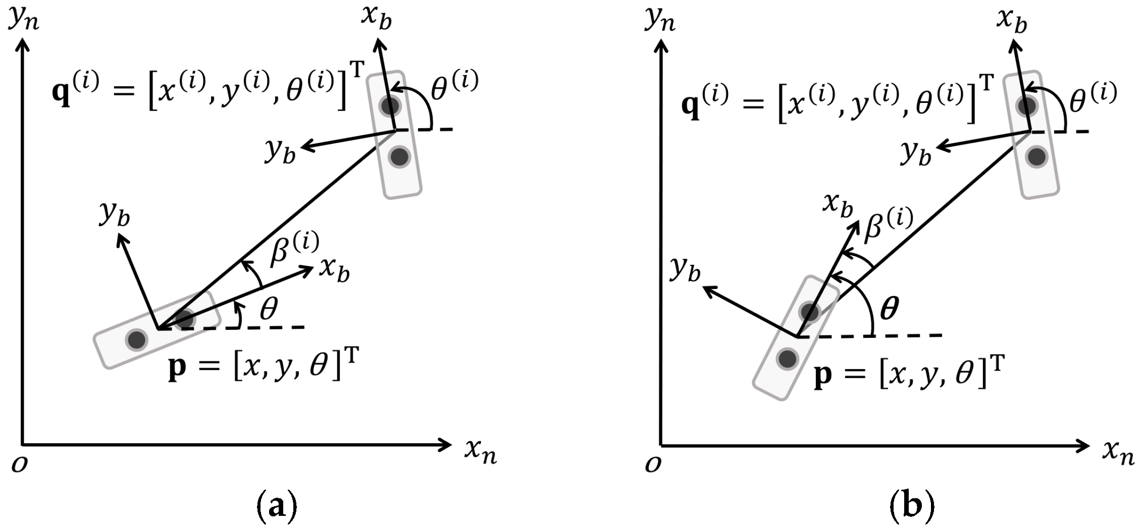
As illustrated in
Figure 1a, we define two coordinate frames: the local reference frame
and the agent’s body frame
. The origin of the body frame is the midpoint of the two UWB antennas, with its positive
-axis aligned with the antenna baseline.
The core measurements are the AoA of signals from the anchors. Let
denote the true AoA of the signal from anchor
as measured in the agent’s body frame. The corresponding measured AoA,
, is modeled as:
where
is Gaussian measurement noise.
The geometric azimuth angle
from the agent to anchor
in the local frame is given by:
3.2. The Front–Back Ambiguity Problem
In an ideal scenario without measurement noise or hardware limitations, the relationship between the geometric angle , the true AoA , and the agent’s orientation would be . However, a fundamental limitation arises from the linear configuration of the dual-antenna array.
The hardware can only resolve the AoA within a 180° field-of-view, outputting a measured AoA
constrained to the range [0°, 180°]. This leads to the front–back ambiguity problem: the same measured AoA
is reported regardless of whether the signal arrives from the front
or the back
of the antenna baseline. Consequently, as depicted in
Figure 1b, the observation model becomes ambiguous, relating the measured angle to the true AoA through two equally plausible hypotheses:
This means that a single measurement is consistent with two possible signal directions: or . This, in turn, leads to two possible solutions for the orientation .
Resolving this ambiguity is the most critical challenge for achieving precise orientation estimation with a single dual-antenna module and forms the central focus of the method proposed in the next section.
4. System Workflow
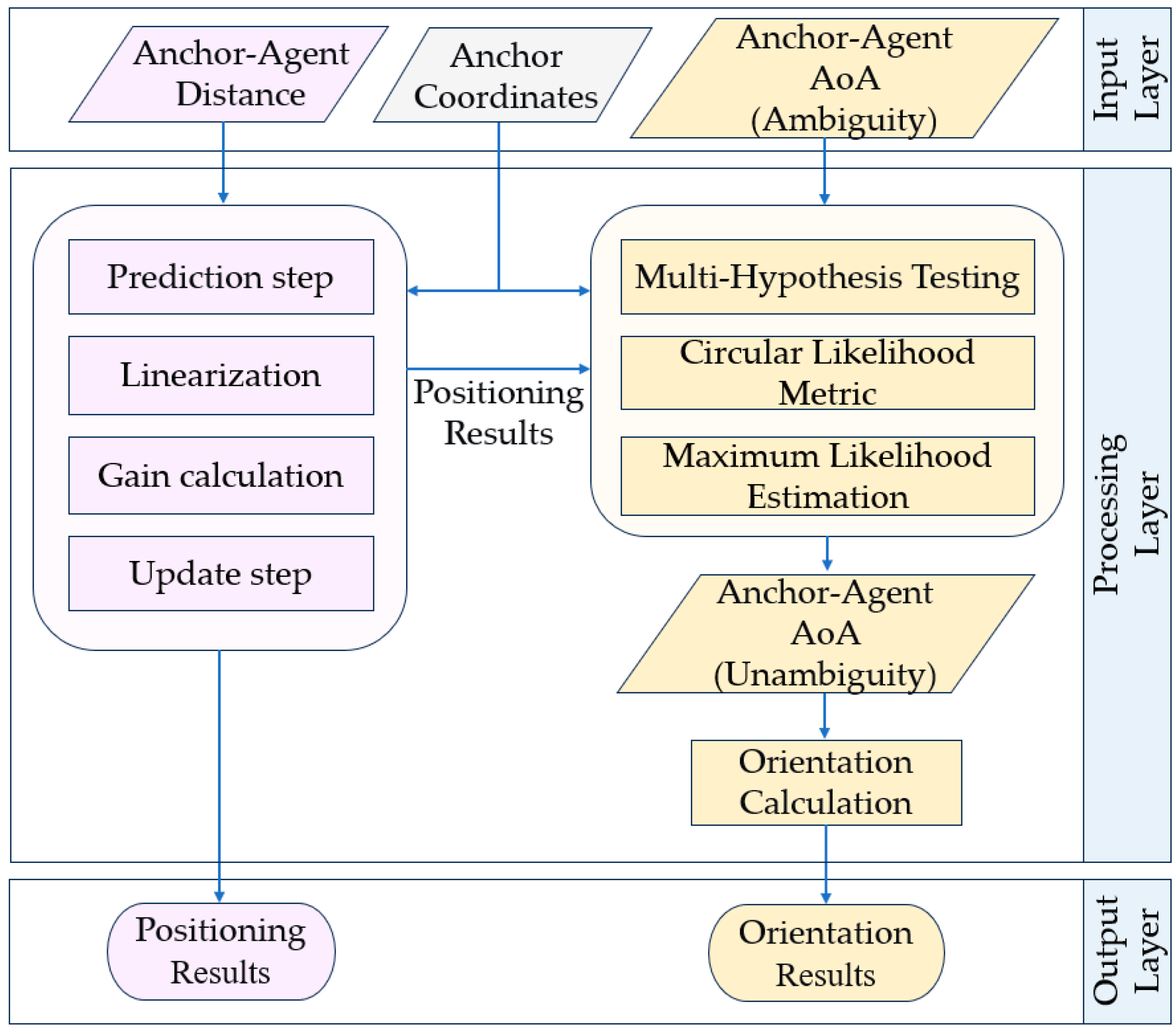
Figure 2 depicts the overall workflow of the proposed system. We refer to this architecture as cascade estimation, as it is divided into two sequential stages: an EKF-based positioning stage (Light Purple) followed by an orientation estimation stage (Light Orange) with front–back ambiguity resolution. This design ensures that the orientation estimation is directly dependent on the preceding positional output. The following subsections detail the core methodologies of each stage.
4.1. EKF-Based Positioning
In this stage, the agent utilizes bidirectional packet exchange with the anchors, whose coordinates are known, to sequentially acquire the distance measurements and the AoA value from each anchor. This subsection focuses on estimating the agent’s position using the distance measurements , where .
While estimating position from range measurements to anchors with known coordinates is a typical multilateration problem most commonly solved using the least-squares algorithm, this method requires range measurements from at least three anchors in a 2D scenario. Otherwise, it fails to yield a unique solution. To enhance the robustness of the positioning computation, we employ the EKF algorithm to calculate the agent’s coordinates. The EKF enables the output of positioning results even when the number of available ranging measurements is fewer than three.
4.1.1. System Model and Formulation
- 1.
State Vector Definition:
Since this stage only estimates the coordinates within the agent’s full unknown state vector , we define the estimated state as , where denotes the time step, and and represent the velocities in the and directions, respectively.
- 2.
State Equation:
We adopt a constant velocity motion model to formulate the system equation. This model assumes the agent moves with approximately constant velocity between consecutive time steps. To compensate for the model’s inherent inaccuracy, a larger process noise covariance is configured, which strategically weights the filter towards the UWB measurements to achieve faster convergence and enhanced robustness. The state equation in matrix form is as follows:
where
is the state transition matrix, given by , and is the sampling time interval.
is the process noise, assumed to be zero-mean Gaussian with covariance matrix . models the uncertainty introduced by the deviations from the constant velocity motion model. The diagonal elements of the matrix represent the variances of the process noise for the corresponding state variables (position and velocity).
- 3.
Observation Equation:
The corresponding observation equation is expressed as:
The vectors and matrices are defined as follows:
: Distance measurements from anchors;
: Nonlinear observation function, mapping the state vector to predicted distances. Since the distance measurement depends only on the agent’s position, each element of the observation function is computed using solely the position components of the state vector: , where and are the position elements of .
: Measurement noise, assumed to be zero-mean Gaussian with covariance matrix .
4.1.2. EKF Recursive Algorithm Steps
The positioning calculation based on the EKF proceeds through the following steps:
- 1.
Prediction Step:
(a) State Prediction: According to the constant velocity model, the predicted state is computed as:
(b) State Covariance Prediction: The covariance matrix associated with the predicted state is given by:
- 2.
Linearization:
The nonlinear observation function
is linearized around the current predicted state
via its Jacobian matrix:
For each anchor node
, the partial derivatives are computed as follows. Not that the observation function depends only on the position
, not the velocity
:
where
is the known position of the
i-th anchor, and
is the position component of the predicted state.
- 3.
Gain Calculation:
(a) Innovation Covariance: The covariance of the measurement innovation is calculated as:
(b) Kalman Gain: The optimal Kalman gain is then obtained by:
- 4.
Update Step:
(a) State Update: The state estimate is updated by incorporating the new measurement
:
(b) Covariance Update: Finally, the state covariance matrix is updated to reflect the reduction in uncertainty after the measurement:
In summary, this EKF positioning module serves as the first stage of the entire system workflow (see
Figure 2). Its output, the position estimate
, provides the fundamental input for calculating the geometric angles
in the subsequent orientation estimation stage.
4.2. Orientation Estimation
With the agent’s 2D coordinates estimated in
Section 4.1, the geometric angle
to each anchor node can be computed via (2). However, due to the front–back ambiguity expressed in (3), measured AoA
alone cannot directly determine the orientation
. This section presents a statistical framework based on two core techniques—MHT and a CLM—to resolve this ambiguity by leveraging constraints from multiple anchors.
4.2.1. MHT Framework
The front–back ambiguity is inherently underdetermined. For
anchors, there exist
geometrically feasible orientation solutions, each corresponding to a unique assignment of
signs to the AoA measurements. We formulate this as an MHT problem, where each hypothesis
is defined by a unique sign vector
, with
. Conceptually, each hypothesis
corresponds to a specific candidate vector of signed AoA measurements:
.
Table 3 illustrates representative hypotheses for
= 4.
For each hypothesis
and anchor
, a candidate orientation estimate is computed by reconciling the geometric angle with the signed AoA measurement:
The term represents the estimated orientation calculated based on from the -th anchor node during the -th hypothesis test. Meanwhile, denotes the geometric angle derived from the coordinates of the -th anchor node and the agent itself.
This yields a set of estimates for hypothesis . The core premise is that only under the correct hypothesis will all these estimates in this set cluster consistently around the true orientation . For incorrect hypotheses, erroneous sign assignments produce dispersed and inconsistent estimates. Therefore, the consistency of the set serves as the criterion for identifying the correct hypothesis .
4.2.2. CLM for Hypothesis Selection
A linear statistic like sample variance is inadequate for measuring the consistency of angular estimates due to wrap-around effects at ±180°. For example, the angle set [178°, 179°, 177°, −179°] would yield a large variance, yet these estimates are, in fact, very close on the unit circle.
To address this, we introduce the CLM, rooted in circular statistics [
18], to evaluate hypothesis consistency. For the set
under hypothesis
, the CLM is computed as the mean resultant length
:
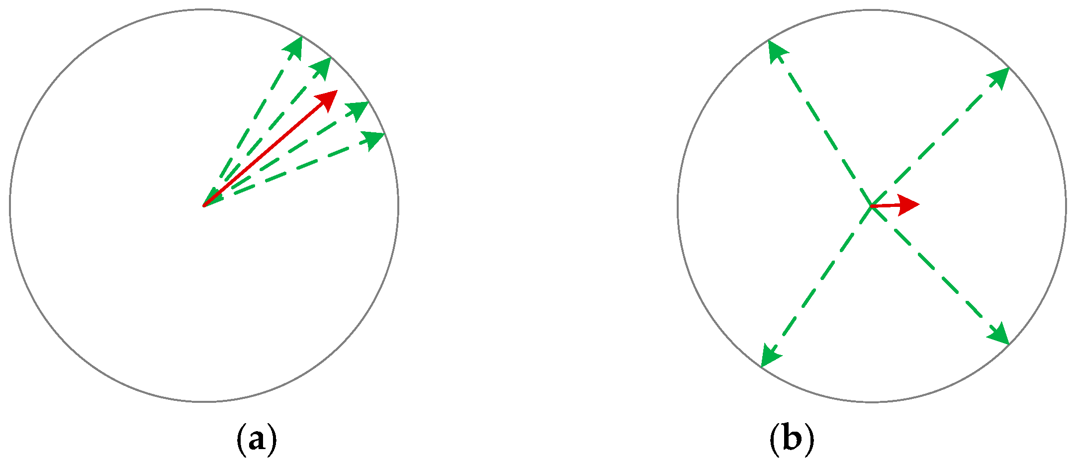
Vector Representation: Convert each angle to a unit vector (represented by a green arrow in
Figure 3) in the complex plane:
.
Vector Summation: Compute the resultant vector sum:
Normalization: Calculate the mean resultant length:
The metric has an intuitive geometric interpretation:
: Unit vectors are highly concentrated, indicating a consistent hypothesis.
: Vectors cancel each other out, indicating an inconsistent hypothesis.
Schematic diagrams of the two scenarios corresponding to
and
are shown in
Figure 3. The length of the red arrows represents the value of
.
We further model the distribution of the estimates under each hypothesis using the von Mises distribution (the circular analogue of the Gaussian). This provides a statistical foundation, showing that the likelihood
that is a monotonic function of
:
Thus, maximizing
is equivalent to maximum likelihood estimation. The optimal hypothesis is selected as:
The final orientation estimate is obtained by taking the median of the set under the selected hypothesis . This strategy is adopted instead of the circular mean to improve robustness, as the median is less sensitive to outliers caused by inevitable multipath effects in practical environments.
In cases of severely deteriorated AoA measurement accuracy, the maximum value may drop below the threshold of 0.9. An orientation estimate derived from such a low value is deemed unreliable; consequently, this results in the rejection of all hypotheses and the withholding of an orientation estimate. The validity of this threshold is demonstrated by our subsequent experiments, in which the optimal hypotheses consistently produced values above 0.95 and delivered correct orientation estimates. Overall, the CLM delivers a robust hypothesis selection criterion, which offers three principal advantages: inherent accommodation of angular wrap-around, improved resilience to outliers, and a normalized consistency measure that carries a clear probabilistic interpretation.
4.3. Discussions
This section has detailed the core methodology of the proposed cascade positioning and orientation system, which jointly estimates the agent’s position and orientation . A key contribution of our work is the use of the CLM to evaluate the consistency of angle sets. In circular statistics, the dispersion of angular data is commonly quantified by the circular variance, denoted as . This metric exhibits a direct and elegant relationship with the CLM’s consistency measure : . Thus, as approaches 1, the circular variance decreases, indicating higher angular consistency and more reliable orientation estimates. This establishes a rigorous statistical basis for the CLM.
On the practical side, although a minimum of three anchors is theoretically sufficient for 2D positioning, we employed four to introduce redundancy and improve robustness. In scenarios with more available anchors, a fixed subset of four with favorable geometry is selected to maintain computational efficiency. Evaluating only 16 hypotheses—a fixed and tractable number—avoids combinatorial explosion and supports real-time operation.
The following sections validate the proposed system through comprehensive Monte Carlo simulations and three real-world experiments, all employing a configuration of four anchor nodes.
5. Simulation Results
5.1. Simulation Setup and Noise Configuration
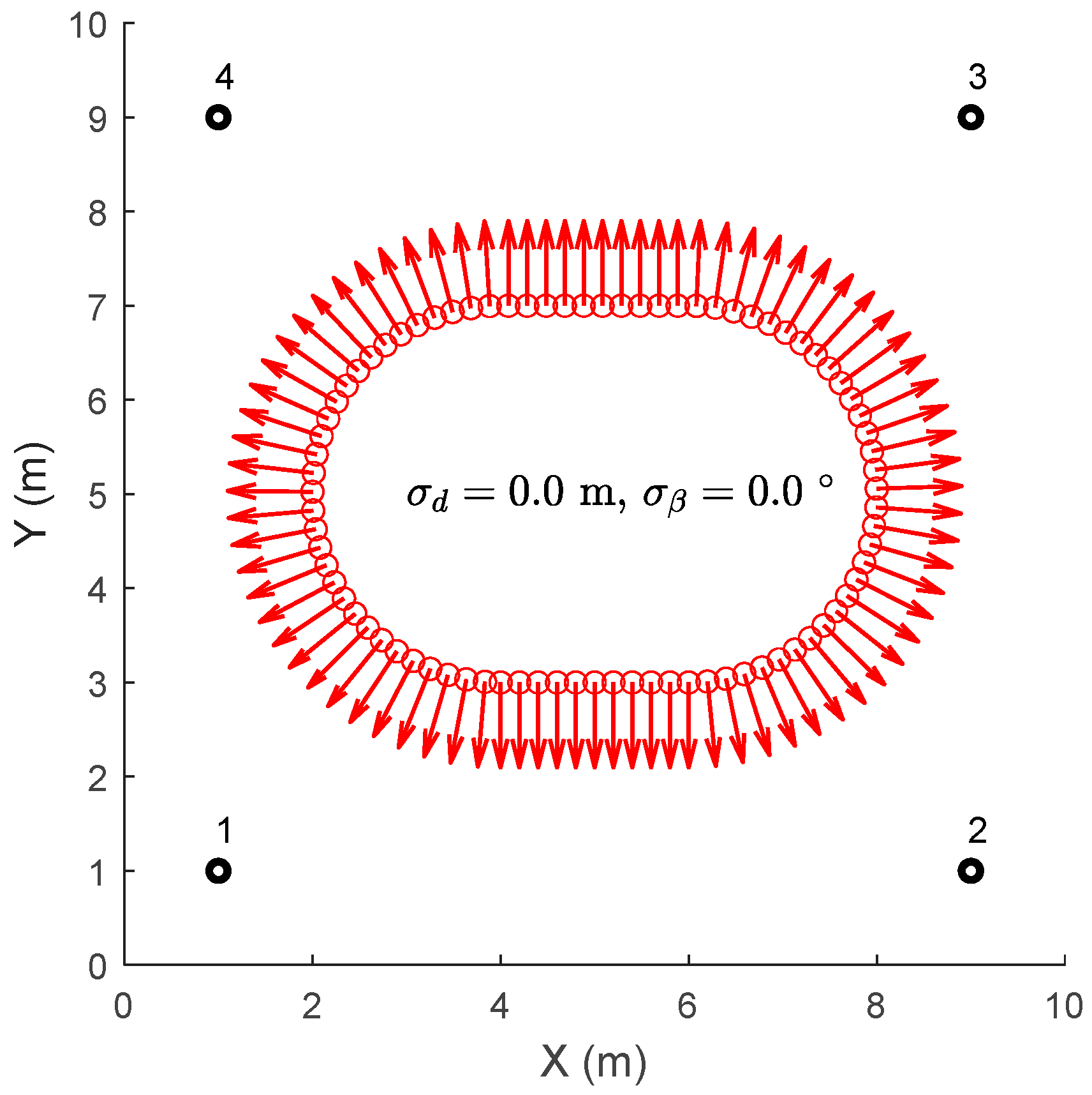
This section details the simulation setup designed to evaluate the proposed cascade estimation approach. The scenario, illustrated in
Figure 4, consists of a localization network with four anchor nodes (black circles labeled 1–4) positioned at the known coordinates (1,1), (9,1), (9,9), and (1,9); all nodes, including the mobile agent, are equipped with dual-antenna UWB modules.
The agent a follows a counterclockwise, symmetrical “race-track” path, starting and ending at (4,3), with a total length of approximately 16.56 m. Moving at a constant speed of 1.0 m/s, the trajectory comprises 83 points and incorporates typical motion patterns such as straight segments, curves, and directional changes. At each trajectory sampling point, the agent’s orientation is indicated by an arrow in
Figure 4. This design enables comprehensive system testing and facilitates intuitive result visualization.
Using the ground-truth coordinates and orientations, the simulation generated the true distance and Angle-of-Arrival (AoA) measurements. These measurements were computed between the agent at each trajectory point and all anchors. To emulate the fundamental limitation of the linear dual-antenna array, the absolute value was applied to all agent-side AoA measurements, thereby folding their range from [−180°, 180°] to [0°, 180°] to create the front–back ambiguity.
The matrix is configured with process noise values of 0.125 m2 for position and 0.05 m2/s3 for velocity, while the matrix is a diagonal matrix with all elements set to 0.04 m2, matching the typical noise variance of UWB ranging and AoA measurements. The EKF recursion was initialized with provided by a least-squares positioning solution. The initial covariance matrix was set as a diagonal matrix, with the variances for the initial position and velocity set to 0.5 m2 and 0.1 (m/s)2, respectively.
To systematically analyze the impact of sensor errors, the simulation employed nine different noise configurations. The standard deviation of the ranging noise was set to {0.1 m, 0.2 m, 0.3 m}, representing typical UWB accuracy, accuracy under mild multipath interference, and accuracy under severe multipath conditions, respectively. Correspondingly, the standard deviation of the angular noise was set to {5°, 10°, 15°} to evaluate performance under varying AoA measurement accuracies.
5.2. Simulation Results and Analysis
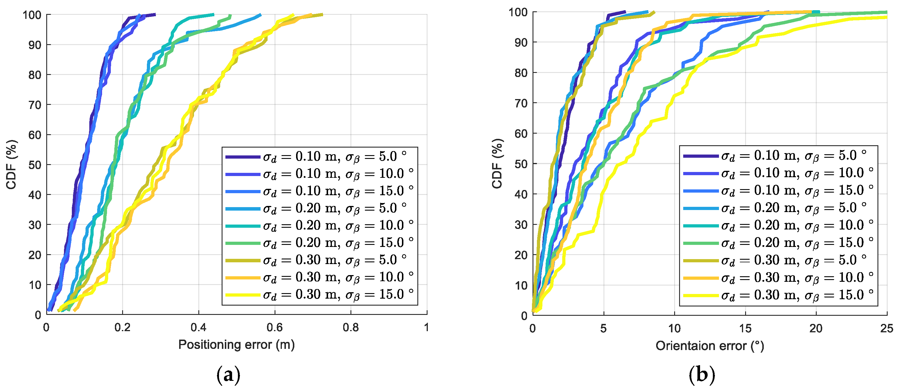
Figure 5 present the cumulative distribution functions (CDFs) of the position estimation error and the orientation estimation error, respectively.
Figure 5a demonstrates that positioning accuracy is predominantly governed by ranging noise. For instance, with
m, the CDF curves for positioning error closely overlap across all levels of angular noise. This validates that the positioning stage, which relies solely on ranging measurements, is effectively decoupled from and insensitive to AoA errors. The results show that in approximately 95% of cases, the positioning error remains below 0.2 m, which aligns with the typical accuracy level of UWB positioning. When
increases to 0.2 m, the positioning error remains below 0.4 m in about 92% of cases.
In contrast, from
Figure 5b reveals a more complex dependency for orientation estimation. Orientation accuracy is primarily determined by angular noise when the AoA measurements are precise. For example, when
= 5°, the orientation error stays within 5° in approximately 95% of cases, largely independent of the ranging error
. This indicates that high-precision AoA measurements can yield satisfactory orientation results even with degraded positioning accuracy.
However, a coupling effect emerges when both error sources are significant. When = 15° and = 0.3 m, the corresponding CDF curve shifts markedly to the right compared to scenarios with lower . These results elucidate how substantial positioning errors propagate through the system model to amplify orientation bias, revealing the critical interaction between ranging and angular errors in the cascaded framework and providing essential insights for practical system design.
5.3. Comparative Analysis with Joint Optimization
As previously established, the proposed cascade estimation approach processes distance and AoA measurements in two distinct, sequential stages. In contrast, the joint optimization method from [
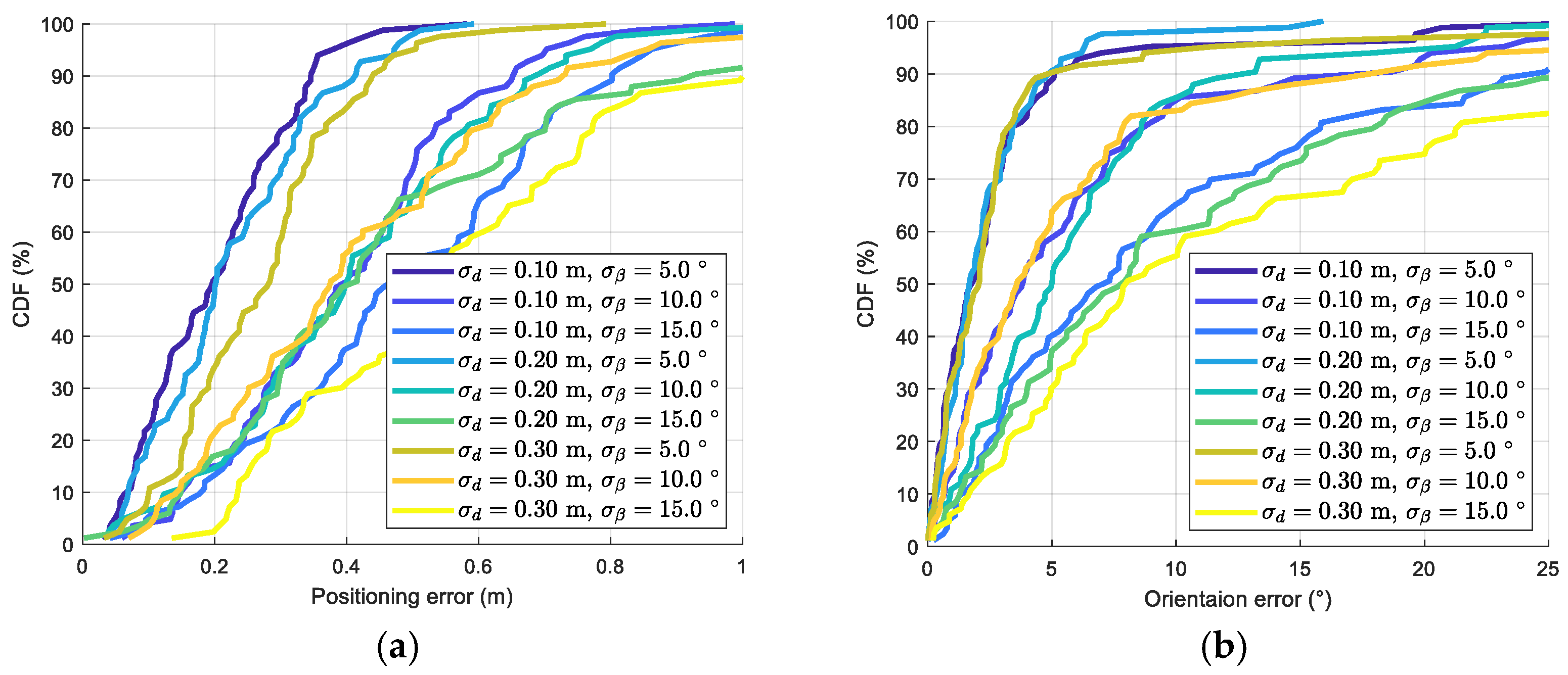
6] fuses both measurement types simultaneously for position and orientation estimation. To provide a benchmark, we reproduced this joint optimization approach under identical simulation conditions and noise configurations for a direct comparison. The results of the joint optimization are presented in
Figure 6.
A comparison between
Figure 6a and
Figure 5a reveals a critical distinction: in the joint optimization approach, with a fixed ranging noise (
= 0.1 m), the positioning error CDF curves show clear separation for different levels of angular noise (
). This confirms a strong coupling effect in the joint optimization framework, where AoA measurement errors directly degrade positioning accuracy.
Overall, under identical noise conditions, the cascade method outperforms the joint optimization approach in both positioning and orientation accuracy, with a more pronounced performance gap in positioning. The underlying reason is error propagation: in the joint optimization approach, AoA errors “contaminate” the position estimates, and the resulting degraded position in turn exacerbates the orientation errors. In contrast, the cascade estimation approach achieves superior performance by effectively decoupling the ranging and AoA estimation errors.
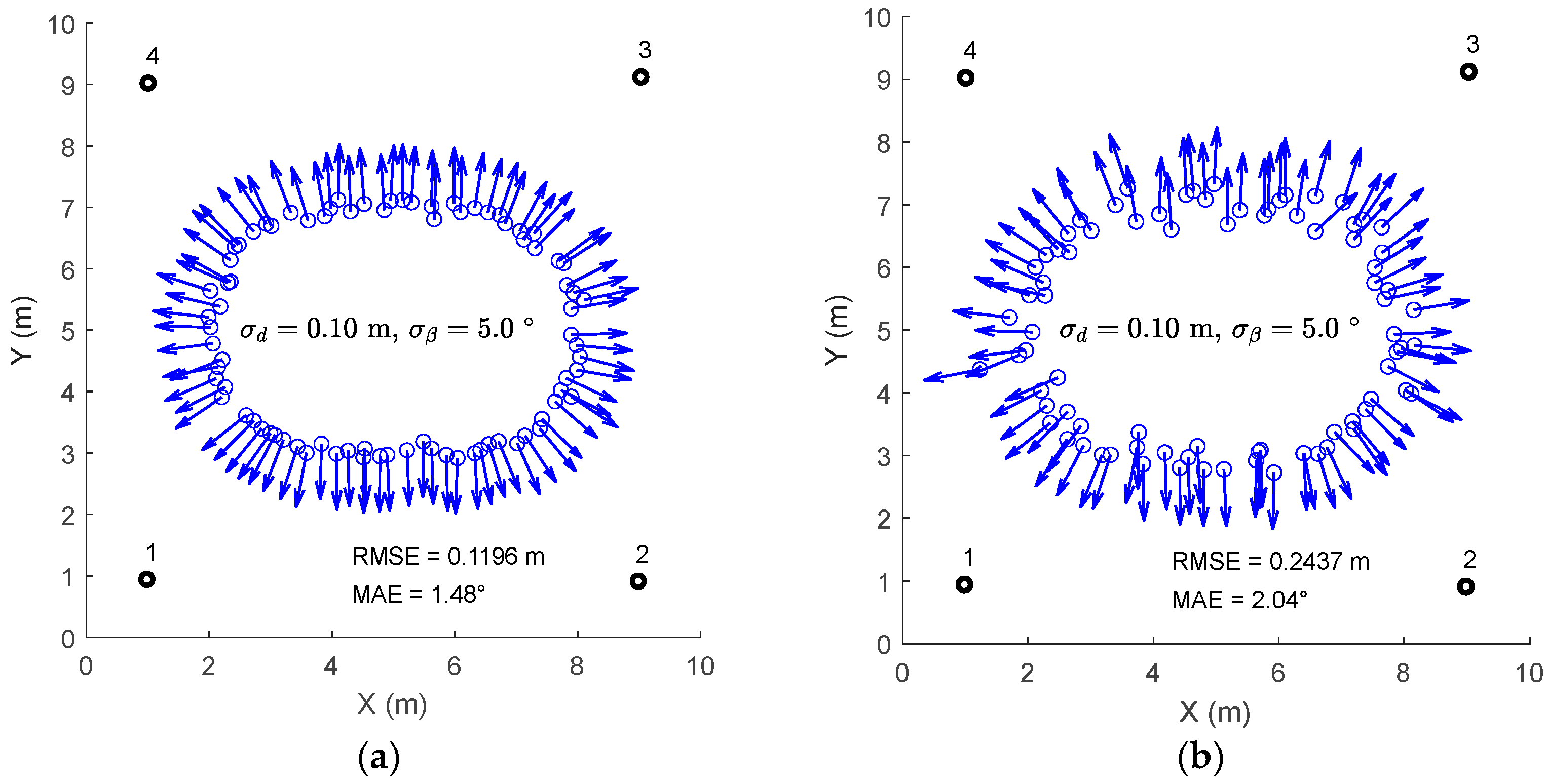
For an intuitive performance comparison,
Figure 7 visualizes the estimated trajectories (blue circles) and orientations (blue arrows) under a typical noise condition (
= 0.1 m,
= 5°). The performance is quantitatively assessed using root mean square error (RMSE), which penalizes large deviations, and mean absolute error (MAE). The latter is preferred for orientation error due to its robustness in handling the circular nature of angular data. As clearly shown in
Figure 7a, the trajectory and orientation estimates of the cascade estimation approach align closely with the ground truth. In contrast, the joint optimization results in
Figure 7b exhibit significant trajectory deviations and scattered orientation estimates. This visual evidence directly confirms the quantitative results, providing intuitive validation for the effectiveness of the proposed method.
In summary, the systematic simulations demonstrate that the proposed cascade estimation approach achieves superior positioning and orientation performance compared to the joint optimization approach under the defined conditions, providing a reliable foundation for practical deployment.
6. Experimental Results
6.1. Hardware Setup
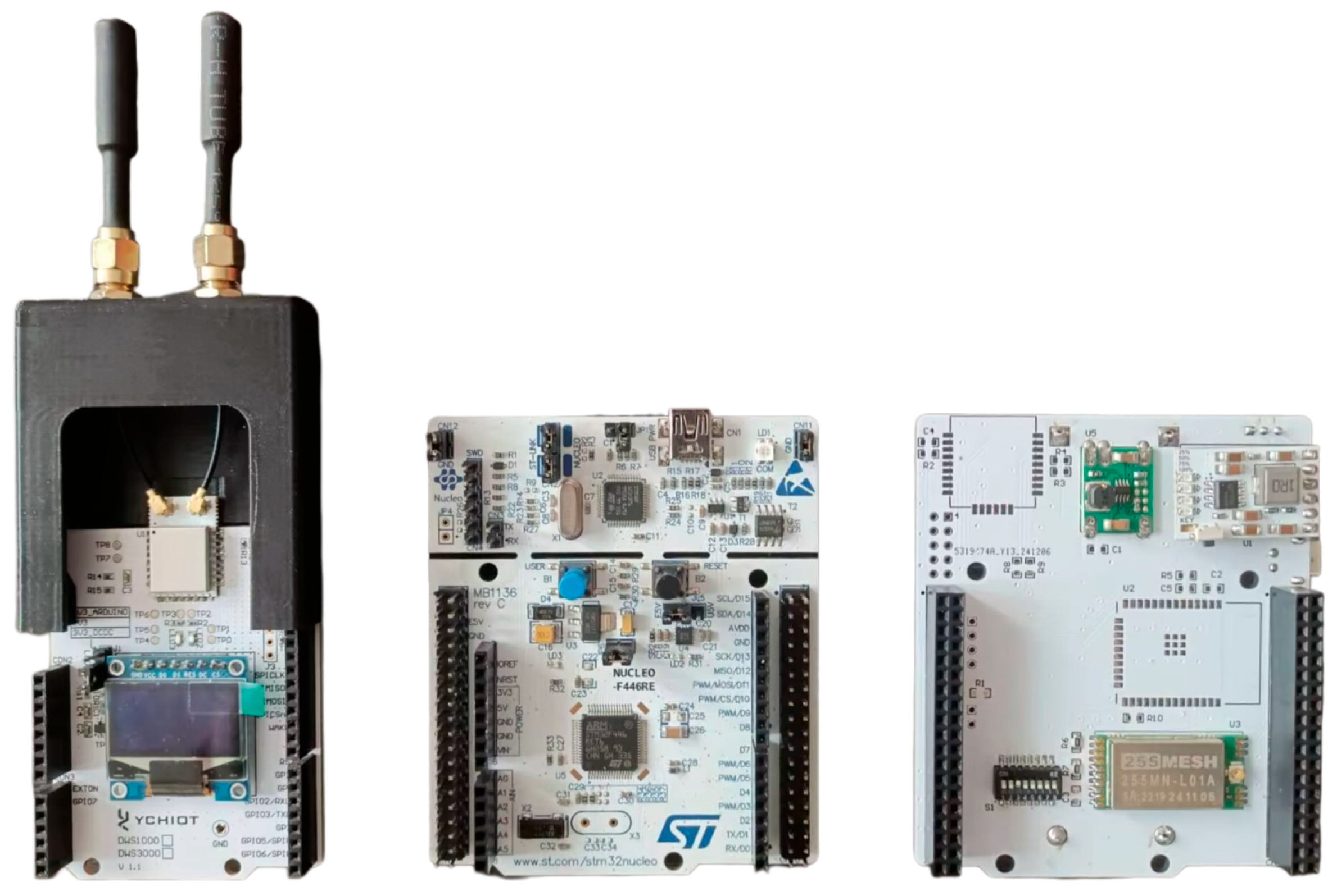
This section evaluates the proposed cascade estimation approach using custom-designed dual-antenna UWB devices based on the DWM3220 module. As illustrated in
Figure 8, each node (agent or anchor) employs a three-board stacked architecture, integrating a UWB board, a CPU board, and a LoRa board.
- 1.
UWB Board
The core component is the DWM3220 UWB module, which interfaces with external devices via SPI. We employed the SS-TWR technique for its shorter transaction time and simpler implementation compared to DS-TWR, making it more suitable for our application. The module operates on Channel 5 (center frequency: 6.5 GHz, bandwidth: 499.2 MHz), yielding a signal wavelength of λ = 4.6 cm. The two receiving antennas are spaced at λ/2 (2.3 cm), a standard configuration optimized for AoA estimation.
- 2.
CPU Board
The CPU board is an STM32 NUCLEO-F446RE development board. Its extensive peripheral set provides significant versatility for data communication and device control. The board’s Arduino-compatible interface is used to seamlessly orchestrate the UWB board’s operations, ensuring coordinated functionality between these core components.
- 3.
LoRa Board
Wireless communication is handled by an industrial-grade LoRa module, effectively overcoming coverage and reliability challenges in complex environments. Designed for plug-and-play operation, the LoRa board interfaces with the CPU board and transmits data to a central gateway. Additionally, it integrates a lithium battery charge–discharge management module and is powered by two 18,650 lithium cells, supplying energy for the entire platform.
The simulations in
Section 5 assume that AoA measurements are affected solely by Gaussian noise. In practice, however, the dual-antenna module exhibits significant nonlinearity. As noted in [
8], good linearity between the measurements and the true values is confined to the 30–150° range. Outside this range, near 0° and 180°, the nonlinearity intensifies, resulting in substantially larger measurement errors. Consequently, during practical experiments, we discard measurements near 0° or 180° and prioritize those within the 30° to 150° range for orientation estimation.
6.2. Rotary Table Experiment
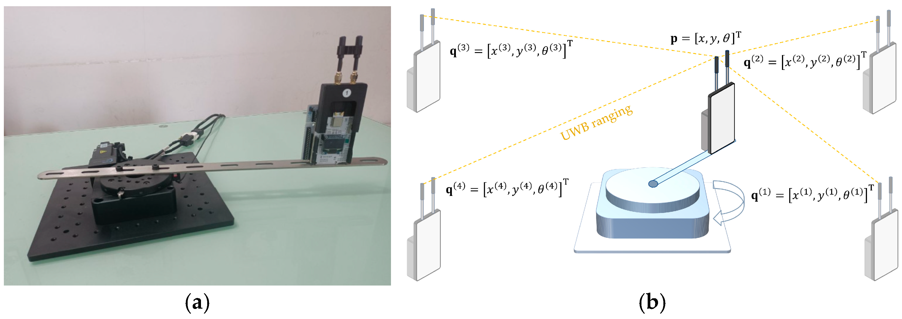
In this experiment, the agent was mounted on a lever arm, positioned 32 cm from the center of the rotary table (
Figure 9a). The rotary table, driven by a servo motor with an angular accuracy better than 0.1°, served as the ground truth source. It rotated clockwise in 20° increments, causing the agent to trace a circular path. Four anchors were deployed around the rotary table at coordinates (135, −125), (135, 125), (−135, 125), and (−135, −125) (in cm). The orientation ground truth was provided by the rotary table’s control software, and the positional ground truth was calculated from the table’s center and the lever arm geometry (
Figure 9b).
At each test point, the agent sequentially communicated with all four anchors to collect ranging and AoA measurements, transmitting the data to a local computer in real-time with each measurement cycle completed within 10 ms.
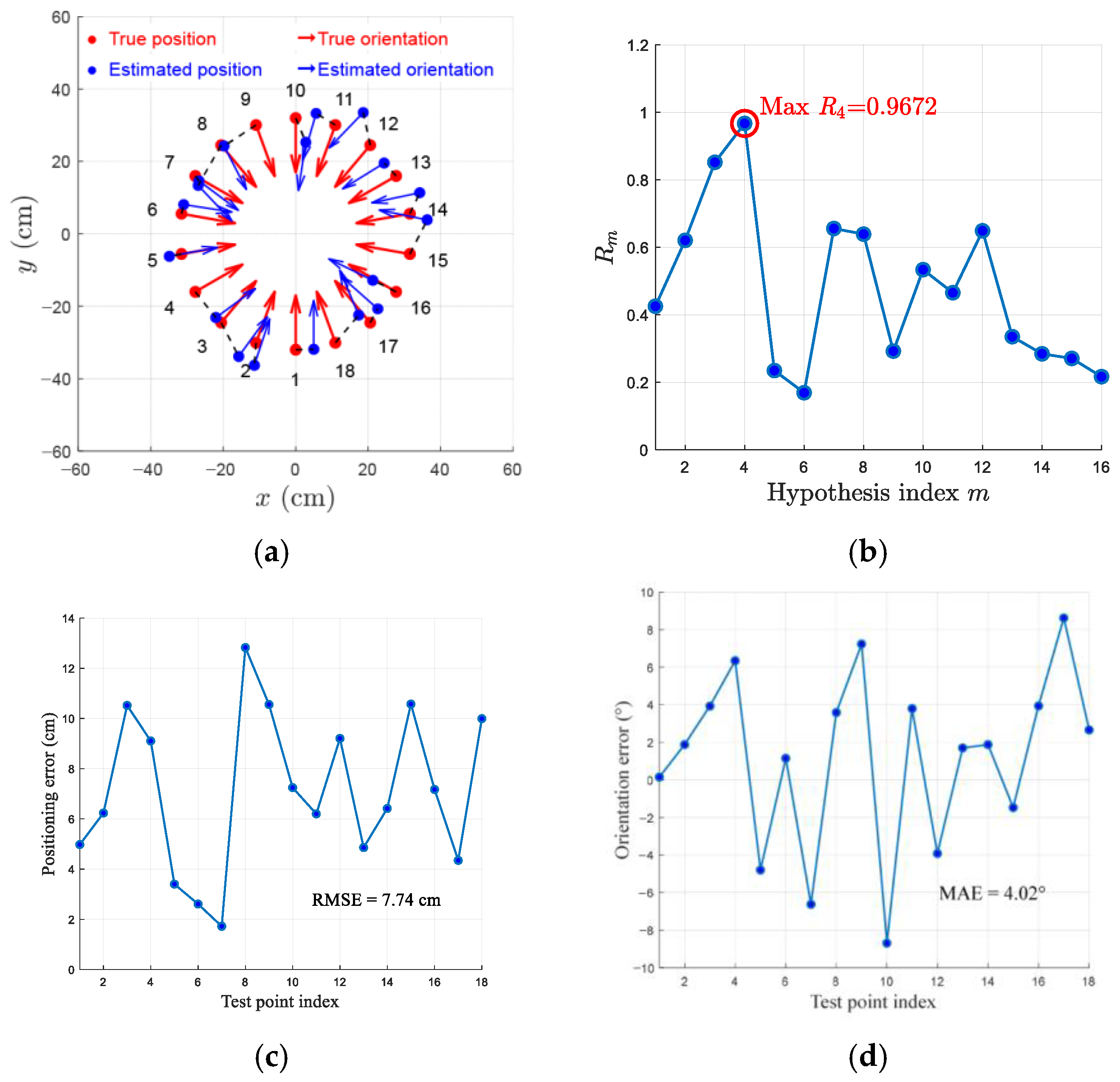
The experimental results of the cascade estimation approach are summarized in
Figure 10. For clarity, the dashed lines in
Figure 10a connect each estimate to its corresponding ground truth, demonstrating that the orientation estimates remain robust despite visible positioning deviations. The system achieved a positioning RMSE of 7.74 cm (
Figure 10c) and an orientation MAE of 4.02° (
Figure 10d).
6.3. Indoor Field Experiment
Real-world indoor positioning is inevitably affected by multipath effects. This experiment was conducted in a materials warehouse (approximately 6 × 6 m
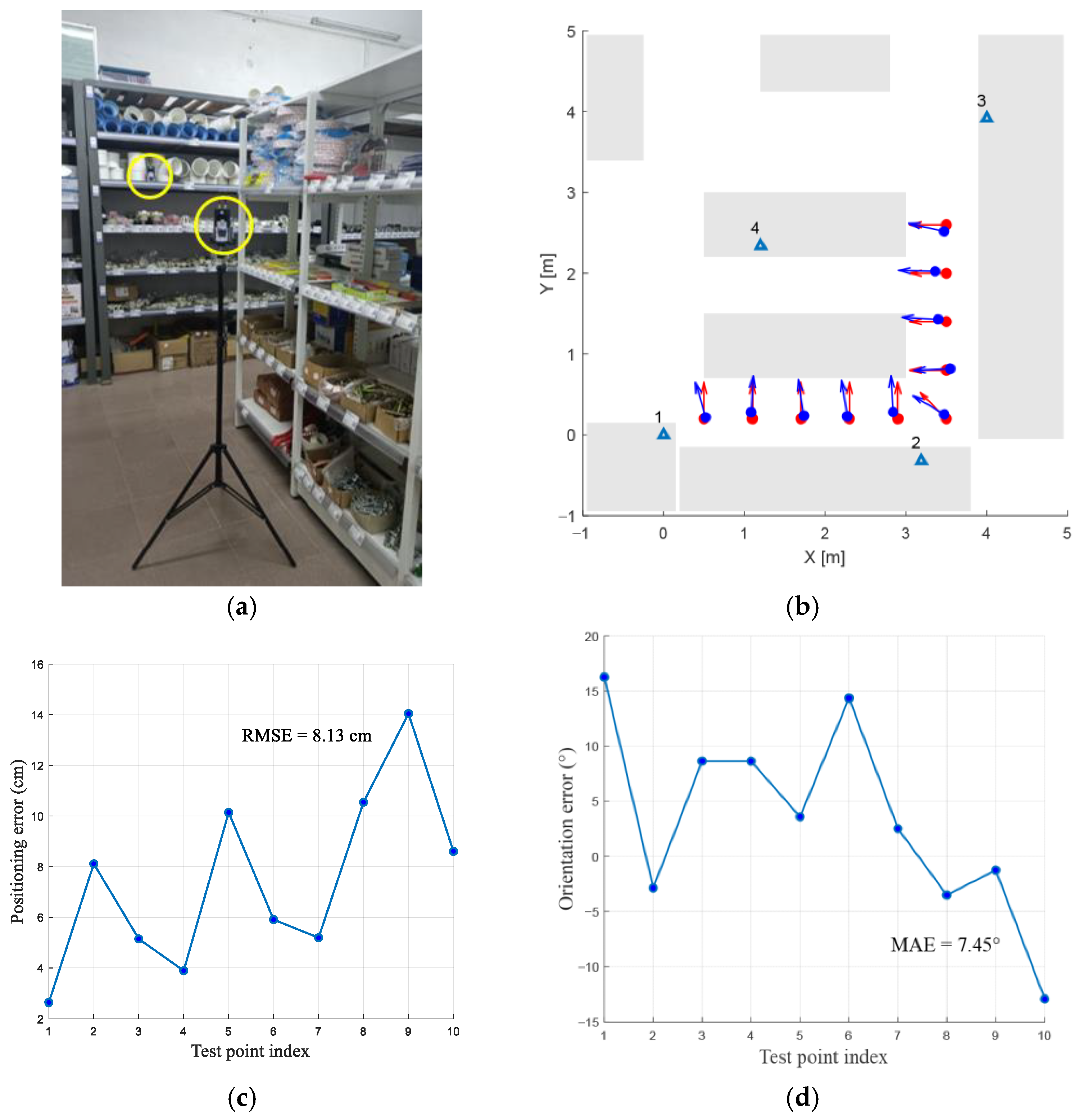
2) surrounded by metal shelves, with two additional rows of shelves in the middle, creating an environment with strong multipath. Four anchor nodes (blue labeled triangles) were mounted on different shelves, and their positions were precisely calibrated (
Figure 11b). The agent, fixed on a tripod at a constant height, was sequentially placed at 10 test points spaced 0.6 m apart. The first test point corresponds to the bottom-left corner in
Figure 11b. At each point, the agent remained static, allowing its true coordinates and orientation to be accurately recorded. Given the static measurement process, the positioning solution was computed directly using a least-squares algorithm without invoking the EKF.
The proposed cascade estimation approach achieved an overall positioning RMSE of 8.13 cm (
Figure 11c), demonstrating robustness against multipath effects and aligning with typical UWB system accuracy. The minimum and maximum positioning errors were 2 cm and 14 cm, respectively. For orientation estimation, the overall MAE was 7.45° (
Figure 11d). The error distribution ranged from −13° to 16°, with both extremes occurring at test points near the edge of the coverage area, likely due to degraded anchor geometry.
6.4. Outdoor Field Experiment
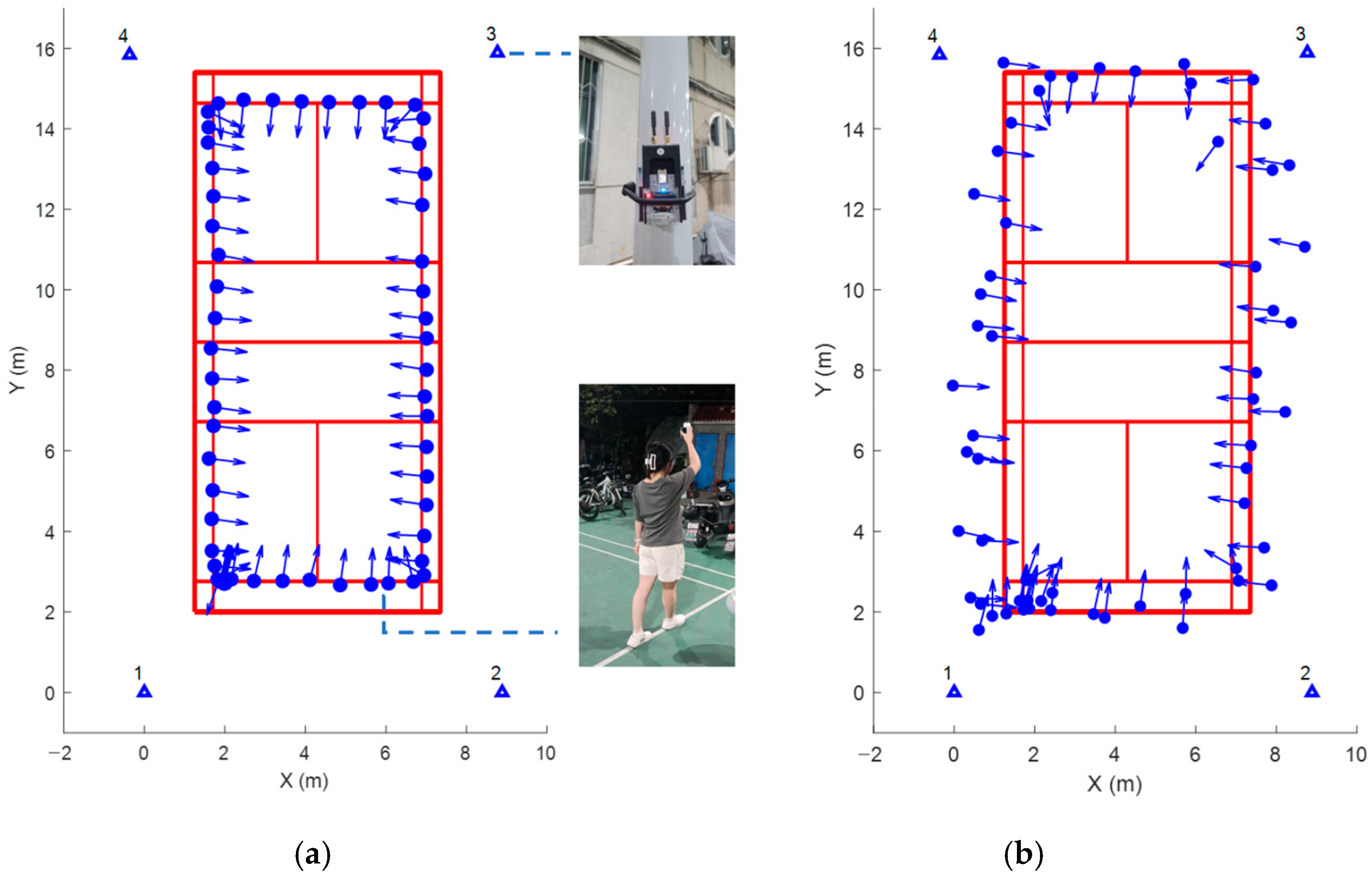
A field experiment was conducted on a standard badminton court to evaluate system performance in a realistic GNSS-denied outdoor environment. The site was surrounded by high-rise buildings, preventing reliable high-precision satellite positioning. Four anchor nodes were symmetrically mounted on light poles at the court corners at a height of approximately 1.8 m. During the experiment, an operator walked along the pre-marked court lines while holding the dual-antenna UWB device, which served as the mobile agent. The device completed a full set of distance and AoA measurements with all four anchors every 0.5 s, outputting real-time trajectory and orientation estimates. All raw data were simultaneously transmitted via LoRa and logged on a laptop for post-processing. The results of both the cascade estimation approach and the joint optimization approach are presented in
Figure 12 for comparison.
In the absence of high-precision ground-truth references in this setting, system feasibility was assessed by visually comparing the estimated trajectory against the physical court lines. The cascade estimation approach showed good consistency with the court lines, whereas the joint optimization approach exhibited noticeable errors in both positioning and orientation—with positioning errors being particularly more pronounced. These results align well with the simulation outcomes presented in
Figure 7. Unlike the static indoor field experiment, the operator’s natural walking motion introduced handheld shaking, resulting in higher fluctuations in the orientation estimates. Despite this, the overall orientation output reliably captured the macroscopic trend of directional changes throughout the movement, demonstrating the system’s basic robustness under dynamic, real-world conditions.
7. Conclusions
This paper introduces the first standalone system that achieves simultaneous positioning and orientation using only a single commercial dual-antenna UWB module, eliminating the need for auxiliary IMUs or complex antenna arrays. By introducing a novel cascaded estimation approach, our work directly solves the fundamental problem of front–back ambiguity, enabling reliable operation in GNSS-denied environments with demonstrated centimeter-level positioning and degree-level orientation accuracy. The core contribution and advantage of this work lies in defining a clear role for dual-antenna UWB: a low-cost, low-power, and computationally efficient solution that delivers reliable spatial awareness for resource-constrained applications such as logistics robots and indoor guidance.
We acknowledge that our system has certain limitations. First, its core mechanism relies on spatial anchor redundancy to resolve ambiguities, making performance sensitive to anchor geometry and density—resulting in degraded performance in sparse or poorly configured deployments. Second, our strategy of discarding AoA measurements in the severe nonlinear regions near 0° and 180°, while effective, inherently reduces measurement availability as a trade-off and depends on the empirically determined thresholds. Finally, strong multipath interference—evident in the warehouse experiment—is not actively mitigated by our UWB-only system.
This comparative analysis highlights the distinctive advantages of our system over mainstream alternatives. Compared to vision-based solutions, our system is immune to lighting variations and requires only an STM32-level embedded processor for real-time operation, eliminating the high computational overhead of visual processing. In contrast to IMU-centric fusion approaches, our UWB-only system employs a substantially simpler state estimation model. Together, these advantages establish our system as a high-performance baseline for cost- and power-sensitive applications, while sensor fusion remains a viable direction for future performance enhancement where added complexity is permissible.
Therefore, this work does not pursue a one-size-fits-all solution but successfully equips commercial UWB systems with a practical, integrated capability. To address these limitations, our future work will pursue the following directions: (1) developing algorithms robust to anchor placement, (2) developing a correction model to compensate for nonlinear AoA errors, thereby increasing measurement availability and robustness without relying on empirical thresholds, and (3) exploring lightweight, loosely coupled IMU integration to enhance multipath resilience in challenging environments such as metal-filled warehouses.
Author Contributions
Conceptualization, C.Z. and P.H.; methodology, Y.L.; software, C.Z.; validation, C.Z. and Y.L.; formal analysis, C.Z.; investigation, Y.L.; resources, P.H.; data curation, C.Z.; writing—original draft preparation, C.Z.; writing—review and editing, Y.L.; visualization, C.Z.; supervision, P.H.; project administration, P.H. All authors have read and agreed to the published version of the manuscript.
Funding
This research received no external funding.
Data Availability Statement
The datasets that support the findings of this study are available on request from the corresponding author, upon reasonable request.
Acknowledgments
The authors would like to thank the editors and reviewers for their detailed reviews and suggestions on the manuscript.
Conflicts of Interest
The authors declare no conflicts of interest.
Abbreviations
The following abbreviations are used in this manuscript:
| UWB | Ultra-wideband |
| EKF | Extended Kalman filter |
| MHT | Multi-hypothesis testing |
| CLM | Circular likelihood metric |
| AoA | Angle of arrival |
| GNSS | Global navigation satellite system |
| VO | Visual Odometry |
| LiDAR | Light Detection and Ranging |
| INS | Inertial navigation system |
| SLAM | Simultaneous localization and mapping |
| SS-TWR | Single-sided two-way ranging |
| DS-TWR | Double-sided two-way ranging |
| STS | Scrambled timestamp sequence |
| IMU | Inertial measurement unit |
| RMSE | Root mean square error |
| MAE | Mean absolute error |
References
- Li, Y.; Zou, X.; Liu, P.; Luo, B.; Pan, W.; Yan, L. Four-element array for GNSS attitude determination using IRLS: An improved rounding of long-short baseline approach. IEEE Trans. Veh. Technol. 2020, 69, 4920–4934. [Google Scholar]
- Campos, C.; Elvira, R.; Rodríguez, J.J.G.; Montiel, J.M.M.; Tardós, J.D. ORB-SLAM3: An accurate open-source library for visual, visual–inertial, and multimap SLAM. IEEE Trans. Robot. 2021, 37, 1874–1890. [Google Scholar]
- Shan, T.; Englot, B.; Meyers, D.; Wang, W.; Ratti, C.; Rus, D. LIO-SAM: Tightly-coupled lidar inertial odometry via smoothing and mapping. In Proceedings of the 2020 IEEE/RSJ International Conference on Intelligent Robots and Systems (IROS), Las Vegas, NV, USA, 24 October 2020–24 January 2021; IEEE: Marina del Rey, CA, USA, 2021; pp. 5135–5142. [Google Scholar]
- Zeng, Z.; Dang, X.; Li, Y.; Huang, Y.; Liang, X. A mmWave radar SLAM method in subterranean tunnel for low visibility and degradation. IEEE Robot. Autom. Lett. 2024, 9, 4281–4288. [Google Scholar]
- Al-Okby, M.F.R.; Junginger, S.; Roddelkopf, T.; Thurow, K. UWB-Based Real-Time Indoor Positioning Systems: A Comprehensive Review. Appl. Sci. 2024, 14, 11005. [Google Scholar]
- Fishberg, A.; Quiter, B.J.; How, J.P. MURP: Multi-agent ultra-wideband relative pose estimation with constrained communications in 3D environments. IEEE Robot. Autom. Lett. 2024, 9, 10612–10619. [Google Scholar]
- Zhang, D.; Xu, H.; Zhan, L.; Li, Y.; Yin, G.; Wang, X. Accurate joint estimation of position and orientation based on angle of arrival and two-way ranging of ultra-wideband technology. Electronics 2025, 14, 429. [Google Scholar]
- Margiani, T.; Cortesi, S.; Keller, M.; Vogt, C.; Polonelli, T.; Magno, M. Angle of arrival and centimeter distance estimation on a smart UWB sensor node. IEEE Trans. Instrum. Meas. 2023, 72, 9508110. [Google Scholar]
- Heydariaan, M.; Dabirian, H.; Gnawali, O. AnguLoc: Concurrent angle of arrival estimation for indoor localization with UWB radios. In Proceedings of the 2020 16th International Conference on Distributed Computing in Sensor Systems (DCOSS), Marina del Rey, CA, USA, 25–27 May 2020; IEEE: Marina del Rey, CA, USA, 2020; pp. 112–119. [Google Scholar]
- Strohmeier, M.; Walter, T.; Rothe, J.; Montenegro, S. Ultra-wideband based pose estimation for small unmanned aerial vehicles. IEEE Access 2018, 6, 57526–57535. [Google Scholar]
- Cao, B.; Wang, S.; Ge, S.; Liu, W. Improving positioning accuracy of UWB in complicated underground NLOS scenario using calibration, VBUKF, and WCA. IEEE Trans. Instrum. Meas. 2020, 70, 8501013. [Google Scholar]
- An, X.; Cui, X.; Zhao, S.; Liu, G.; Lu, M. Efficient rigid body localization based on euclidean distance matrix completion for AGV positioning under harsh environment. IEEE Trans. Veh. Technol. 2022, 72, 2482–2496. [Google Scholar]
- Hamer, M.; D’Andrea, R. Self-calibrating ultra-wideband network supporting multi-robot localization. IEEE Access 2018, 6, 22292–22304. [Google Scholar]
- Li, X.; Wang, Y.; Li, B.; Gao, X.; Li, Z.; Li, S. A cooperative relative localization system for distributed multi-agent networks. IEEE Trans. Veh. Technol. 2023, 72, 14828–14843. [Google Scholar]
- Zhao, H.; Xu, L.; Li, Y.; Wen, F.; Gao, H.; Liu, C.; Yu, J.; Wang, Y.; Shen, Y. Robust and Scalable Multi-Robot Localization Using Stereo UWB Arrays. IEEE Trans. Robot. 2025, 41, 5645–5662. [Google Scholar]
- Bach, S.-H.; Yi, S.-Y. A Tightly Coupled Approach for Simultaneous Anchor and Tag Localization With Multi-UWB-Tag System. IEEE Sens. J. 2025, 26, 1320–1328. [Google Scholar]
- Fischer, G.K.J.; Schaechtle, T.; Gabbrielli, A.; Bordoy, J.; Häring, I.; Höflinger, F.; Rupitsch, S.J. A Systematic Survey and Comparative Analysis of Angular-Based Indoor Localization and Positioning Technologies. IEEE Commun. Surv. Tutor. 2025, 28, 3830–3869. [Google Scholar]
- Fisher, N.I. Statistical Analysis of Circular Data; Cambridge University Press: Cambridge, UK, 1993. [Google Scholar]
| Disclaimer/Publisher’s Note: The statements, opinions and data contained in all publications are solely those of the individual author(s) and contributor(s) and not of MDPI and/or the editor(s). MDPI and/or the editor(s) disclaim responsibility for any injury to people or property resulting from any ideas, methods, instructions or products referred to in the content. |