2.13. Reproducibility and Data Availability
The simulations were deterministic. Component tolerances, sensor offsets, initial conditions, noise sequences, switching carrier phases, communication timing, controller delays, and optimization settings were fixed so that repeated simulations produced identical results.
The model was developed in MATLAB R2026a. Reproducibility requires the complete electrical parameter set, coupling filter tolerances, semiconductor model, controller gains, QUBO weights, variational circuit configuration, FSM thresholds, ADC models, and coherent FFT evaluation intervals reported in the manuscript and accompanying parameter files.
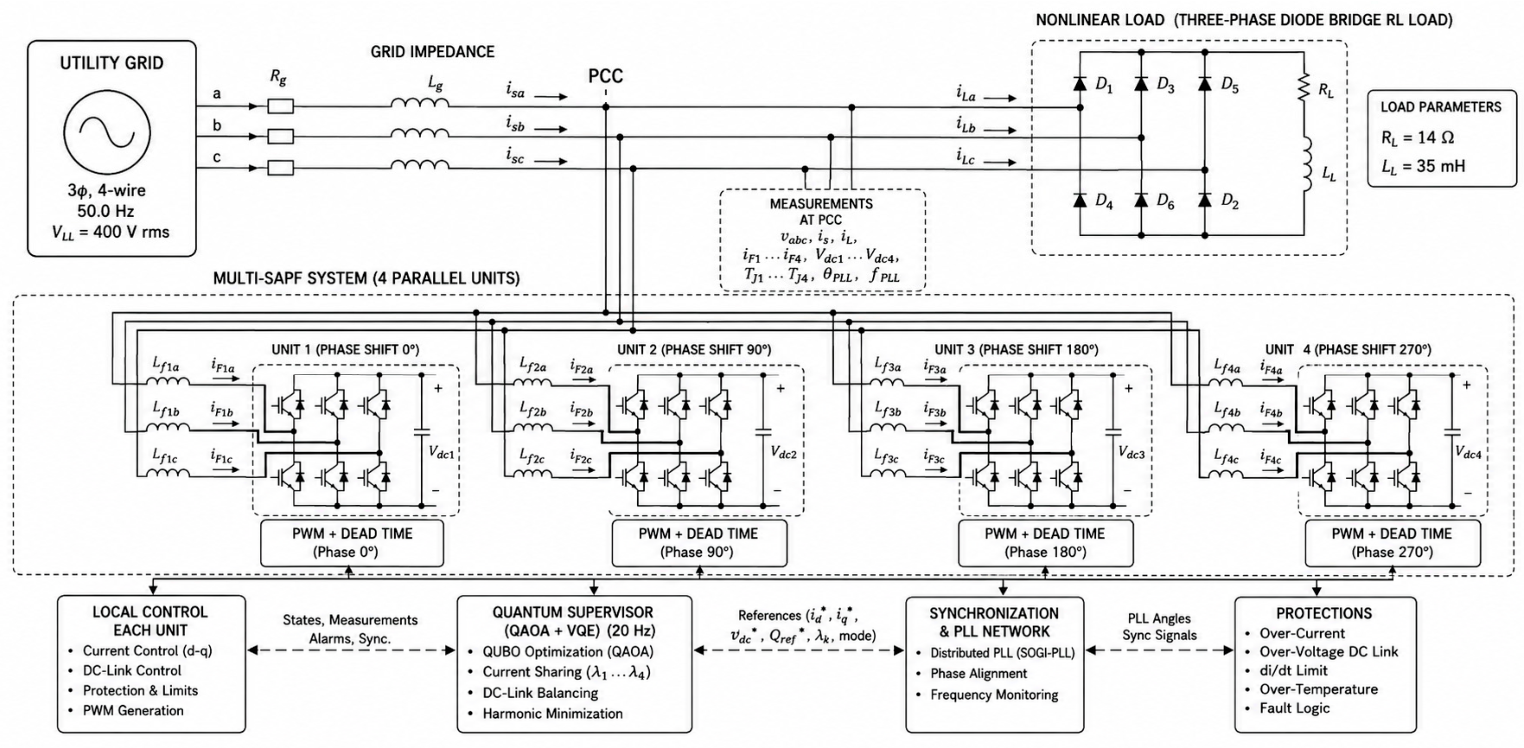
Figure 1 presents the complete architecture of the proposed Quantum Multi-SAPF Hybrid-Switching Power System, integrating the electrical power stage, distributed active power filters, measurement infrastructure, synchronization network, local controllers, quantum supervisory optimization, and protection functions into a unified cyber–physical control platform. The architecture has been designed to achieve simultaneous harmonic mitigation, reactive power compensation, optimal current sharing, DC-link energy balancing, and safe converter operation while satisfying IEEE 519 harmonic limits.
The proposed system consists of a three-phase utility grid supplying a nonlinear six-pulse diode bridge RL load through a realistic feeder impedance.
The Point of Common Coupling (PCC) is the central electrical node where the utility grid, the nonlinear load, and the four parallel SAPFs are interconnected. All electrical quantities required by the supervisory controller, including , , , −, and −, converter temperatures, and synchronization variables, are continuously measured at this location.
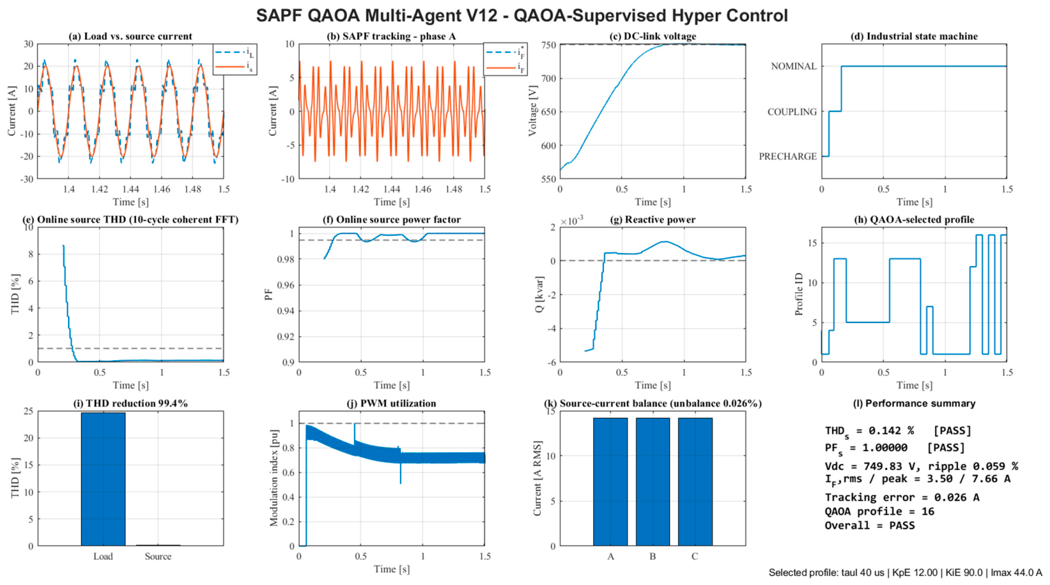
The nonlinear load is modeled as a three-phase six-pulse diode bridge rectifier supplying an RL load, consistent with the MATLAB R2026a simulation framework. Under the investigated operating condition, the nonlinear converter load produces a strongly distorted three-phase current waveform with a measured load current THD of 24.615%. This distorted current constitutes the uncompensated reference condition used to assess the performance of the proposed SAPF. After activation of the QAOA-supervised multi-agent compensation system, the source current THD is reduced from 24.615% to 0.142%, corresponding to a reduction in harmonic distortion. Simultaneously, the compensated grid-side operation achieves a source power factor of 0.99999, limits the residual source reactive power to 0.31 var, and maintains a balanced source RMS current of 14.262 A. These results confirm that the proposed controller effectively isolates the utility grid from the nonlinear current demand of the six-pulse rectifier while providing simultaneous harmonic and reactive current compensation. Because the nonlinear load current exhibits a THD of 24.615%, the total apparent power cannot be represented solely by the fundamental relation of apparent power. Under nearly sinusoidal supply voltage conditions, harmonic current introduces an additional distortion power component. The fundamental apparent power is approximately 13.08 kVA. Including harmonic-current RMS contribution increases total apparent power to approximately 13.47 kVA. The corresponding distortion power term is approximately 3.22 kVA.
The compensation system is composed of four identical shunt active power filters connected in parallel at the PCC. Each converter is coupled to the network through three dedicated inductors (−), having a nominal value of 3.0 mH per phase with 0.030 Ω winding resistance. These inductors attenuate switching harmonics, limit current gradients, suppress circulating currents, and ensure stable current regulation.
Each SAPF contains a two-level IGBT voltage source inverter supplied by an independent 750 V DC-link and controlled by a local real-time controller operating at 15 kHz. The local controllers perform current regulation, DC-link voltage control, PWM generation, and protection independently of the supervisory optimization layer.
The converters employ phase-interleaved PWM with carrier phase shifts of 0°, 90°, 180°, and 270°. Interleaving distributes switching events uniformly over the switching period, reducing the overall current ripple injected into the PCC without increasing the switching frequency of individual converters.
The global coordination is performed by the QAOA–VQE quantum supervisory controller, executed every 50 ms (20 Hz). The QAOA optimizer determines the optimal participation factors for the four SAPFs, balancing current sharing, converter utilization, harmonic compensation, and DC-link energy. The VQE optimizer subsequently computes optimal predictive current references while minimizing harmonic distortion, reactive power, thermal stress, and DC-link voltage deviations under the imposed operating constraints.
A distributed synchronization network based on SOGI-PLL maintains coherent operation of all converters by continuously aligning phase angles and tracking the grid frequency.
The protection layer continuously supervises converter current, DC-link voltage, current gradients, junction temperature, and fault conditions. The validated results confirm safe operation throughout the simulation.
The complete system satisfies the physical current balance at the PCC,
where the distributed SAPFs collectively inject the compensating currents required to eliminate harmonic and reactive components from the source current.
The proposed architecture combines fast deterministic local control with quantum-assisted supervisory optimization. The validated results demonstrate a reduction in source current THD %, an improvement in the source power factor, reactive power compensation while maintaining balanced DC-link voltages, and safe operation of all converters.
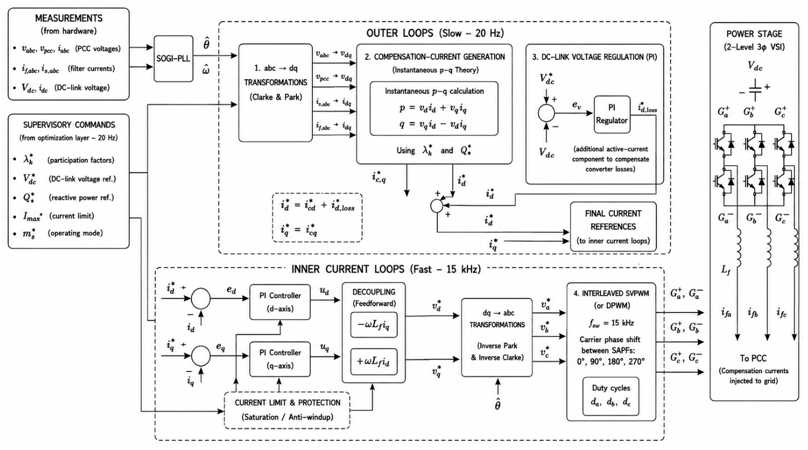
Figure 2 illustrates the complete cascaded control architecture of the proposed three-phase Shunt Active Power Filter (SAPF), organized as a hierarchical multi-rate control system. The controller is divided into two coordinated layers operating at different sampling frequencies. The outer supervisory loops are executed at approximately 20 Hz and are responsible for determining the optimal compensation current references and regulating the DC-link energy. The inner current control loops operate at 15 kHz, ensuring high-bandwidth tracking of the reference currents through predictive current regulation and pulse-width modulation. This hierarchical organization separates slow energy management tasks from fast current dynamics, improving stability, robustness, and computational efficiency.
The left-hand side of the architecture represents the measurement subsystem, which continuously acquires the electrical quantities required for feedback control.
The measured variables are:
Three-phase PCC voltages ;
Filter currents , DC-link voltage
These measurements constitute the physical interface between the converter and the electrical network and are updated every sampling interval.
- 2.
Grid Synchronization
The measured voltages are processed by a Second-Order Generalized Integrator Phase-Locked Loop (SOGI-PLL).
The PLL estimates and which represent the instantaneous grid angle and frequency.
Accurate synchronization is essential because every transformation between the stationary and synchronous reference frames depends on the estimated electrical angle.
The SOGI-PLL provides excellent harmonic rejection while maintaining rapid synchronization under distorted grid conditions.
- 3.
Supervisory Commands
The optimization layer generates supervisory references that define the operating point of the SAPF.
These commands include:
Participation factor , which determines the amount of compensation required (allocates aggregate compensation among converters);
DC-link voltage reference
Reactive power reference
Maximum admissible filter current
Operating mode
These supervisory variables allow higher-level optimization algorithms, such as multi-agent coordination or QAOA-based optimization, to adapt the controller according to network conditions.
- 4.
abc–dq Transformations
The first block of the outer loop performs Clarke and Park transformations.
Using the estimated angle the measured three-phase quantities are converted into the synchronous rotating frame,
The transformation produces which simplifies the control problem because balanced sinusoidal variables become approximately constant in steady state.
This transformation decouples active and reactive power regulation.
- 5.
Compensation Current Generation
The second block implements the instantaneous p–q theory.
The instantaneous active and reactive powers are computed as
Using the supervisory participation factor together with the reactive power reference the controller determines the compensation current references and
These currents correspond to the harmonic and reactive components that must be injected by the SAPF to force the source current toward a sinusoidal waveform.
- 6.
DC-Link Voltage Regulation
The third outer loop regulates the DC-link capacitor voltage. The measured voltage is continuously compared with its reference The voltage error is processed by a PI controller. Its output generates an additional active-current component which compensates converter conduction and switching losses while maintaining constant DC-link energy. The final reference currents become and This summation ensures that harmonic compensation and DC-link energy regulation are performed simultaneously without interfering with each other.
- 7.
Current References
The outputs of the outer loops are combined to generate the final reference vector supplied to the inner controller.
The reference current vector contains all the information required for harmonic mitigation, reactive power compensation, and converter loss compensation.
- 8.
Inner Current Control Loops
The lower part of the figure represents the fast current control layer.
The measured currents are compared with their references
The resulting errors are processed by independent PI regulators.
The regulators generate the voltage commands Because the synchronous reference frame introduces cross-coupling terms, a feedforward decoupling network is employed.
The decoupling voltages and compensate the coupling between the two control axes, allowing both PI regulators to operate independently.
Consequently, the dynamic response becomes faster and overshoot is reduced.
- 9.
Current Limitation and Protection
Before modulation, the reference currents pass through a protection block. This subsystem performs current saturation, anti-windup, and converter protection. The objective is to guarantee that under every operating condition. This prevents semiconductor overcurrent and preserves converter reliability.
- 10.
Inverse Transformations
The compensated voltage references are transformed back into three-phase quantities through the inverse Park and Clarke transformations.
The controller, therefore, produces which constitute the voltage references required by the PWM modulator.
- 11.
PWM Modulation
The architecture employs interleaved Space Vector PWM (SVPWM) or Discontinuous PWM (DPWM) operating at Carrier phase shifts of are used between parallel SAPF modules.
Interleaving significantly reduces output current ripple, DC-link current ripple, and electromagnetic interference, while increasing converter efficiency.
The PWM generates the duty cycles from which the gate signals are produced.
- 12.
Power Stage
The right-hand side illustrates the physical converter.
The SAPF consists of a two-level three-phase voltage source inverter, DC-link capacitor, and coupling inductors which inject the compensation currents into the Point of Common Coupling (PCC). The converter synthesizes the compensation voltages generated by the controller and produces the required harmonic compensation current.
- 13.
Signal Summary
The summaries of all controller inputs and outputs are as follows.
Inputs: three-phase voltages, three-phase currents, DC-link voltage, PLL angle, and supervisory references.
Outputs: converter voltage references, PWM duty cycles, gate signals, and injected compensation currents. This block clearly defines the interface between the digital controller and the physical converter.
Overall Control Principle
The complete control architecture follows a cascaded hierarchy. The slow outer loops estimate the instantaneous power components, regulate the DC-link energy, and generate optimal current references based on supervisory commands. The fast inner loops then ensure that these references are accurately tracked through decoupled PI current regulation, coordinate transformations, and high-frequency PWM modulation. Finally, the power converter injects the required compensation currents into the grid through the coupling inductors, forcing the source current to become sinusoidal and nearly in phase with the PCC voltage.
This hierarchical organization offers several advantages over conventional single-loop controllers. By separating energy regulation from current regulation, the controller achieves independent tuning of slow and fast dynamics, improving transient response and steady-state accuracy. The feedforward decoupling network minimizes cross-coupling between the - and -axes, enabling rapid current tracking and reducing overshoot. Furthermore, the modular supervisory interface allows advanced optimization methods—including multi-agent coordination, adaptive control, or QAOA-based supervisory optimization—to update the outer-loop references without modifying the proven inner current control structure. Consequently, the architecture provides a scalable and industrially robust framework capable of delivering high-quality harmonic compensation, nearly unity power factor, stable DC-link voltage regulation, and safe converter operation under widely varying operating conditions.
The control architecture of the proposed three-phase Shunt Active Power Filter (SAPF) is organized into two hierarchical control levels operating at different time scales (
Figure 2). The architecture separates slow supervisory functions from high-speed current regulation, allowing independent optimization of energy management and converter dynamics. This hierarchical organization significantly improves stability, simplifies controller tuning, and enables the integration of advanced supervisory optimization algorithms without affecting the deterministic behaviour of the inner current controller.
The control process begins with the measurement subsystem, where the three-phase PCC voltages, filter currents, and DC-link voltage are continuously acquired. These signals provide the real-time electrical state of the converter and the power system. The measured voltages are processed by a Second-Order Generalized Integrator Phase-Locked Loop (SOGI-PLL), which accurately estimates the grid angle and frequency even under distorted operating conditions. The estimated electrical angle establishes the synchronous reference frame required by all subsequent control algorithms.
The supervisory optimization layer supplies high-level operating commands, including the participation factor, DC-link voltage reference, reactive power reference, converter current limit, and operating mode. These supervisory variables allow adaptive optimization algorithms to modify the operating point of the SAPF according to the instantaneous grid conditions, harmonic content, or converter operating constraints while maintaining complete compatibility with the lower-level deterministic controller.
Within the outer control loops, the measured three-phase voltages and currents are transformed into the synchronous reference frame using the Clarke and Park transformations. In this rotating reference frame, the sinusoidal variables become nearly constant under steady-state conditions, allowing active and reactive power to be regulated independently. The transformed quantities form the basis for the instantaneous power calculations used throughout the supervisory control layer.
The compensation current generation block implements the instantaneous - theory to determine the active and reactive current components required for harmonic mitigation and reactive power compensation. The instantaneous active and reactive powers are calculated from the -axis voltages and currents, while the supervisory participation factor and reactive power reference determine the desired compensation level. Consequently, the controller generates the reference compensation currents that eliminate harmonic distortion and force the source current to remain sinusoidal and nearly in phase with the supply voltage.
The second outer loop performs DC-link voltage regulation. The measured capacitor voltage is continuously compared with its reference, and the resulting voltage error is processed by a proportional–integral controller. Rather than modifying the harmonic compensation strategy, this controller produces an additional active-current component that compensates converter conduction and switching losses while maintaining constant DC-link energy. The active current generated by the voltage controller is added to the compensation current reference, producing the final current references supplied to the inner control loops.
The inner current control layer operates at the converter switching frequency and provides the fast dynamic response required for accurate current tracking. Independent PI controllers regulate the - and -axis currents using the errors between the measured and reference currents. To eliminate the dynamic coupling naturally introduced by the synchronous reference frame, feedforward decoupling terms proportional to the filter inductance and grid frequency are added to the controller outputs. This compensation significantly improves bandwidth, reduces overshoot, and enables independent regulation of the active and reactive current components.
Before modulation, the controller incorporates current limitation and anti-windup protection to guarantee that the commanded current remains within the converter Safe Operating Area (SOA). These protection mechanisms prevent excessive semiconductor stress while preserving the dynamic response of the current regulators. As a result, converter reliability is maintained even during severe load transients or abnormal operating conditions.
The compensated voltage references generated by the current controllers are transformed back into three-phase quantities through the inverse Park and inverse Clarke transformations. These three-phase voltage references are subsequently processed by an interleaved Space Vector Pulse-Width Modulation (SVPWM) or Discontinuous PWM (DPWM) strategy operating at a switching frequency of 15 kHz. The phase-shifted carrier arrangement reduces current ripple, distributes switching losses more uniformly among parallel converters, and improves overall converter efficiency.
The power stage consists of a conventional two-level three-phase voltage source inverter supplied by the regulated DC-link capacitor. Through the coupling inductors, the inverter injects the calculated compensation currents into the Point of Common Coupling (PCC), thereby cancelling the harmonic and reactive components drawn by the nonlinear load. Consequently, the utility supplies only the balanced fundamental active current required by the load, while the SAPF provides the remaining compensation currents.
The proposed cascaded architecture combines slow supervisory optimization with fast deterministic current regulation in a physically consistent and computationally efficient framework. The outer loops determine the optimal compensation objectives and maintain DC-link energy, whereas the inner loops guarantee precise current tracking through high-bandwidth decoupled control and PWM modulation. This modular organization facilitates the integration of advanced optimization techniques (QAOA-based supervisory optimization) while preserving the robustness, stability, and real-time performance required for industrial active power filtering applications.
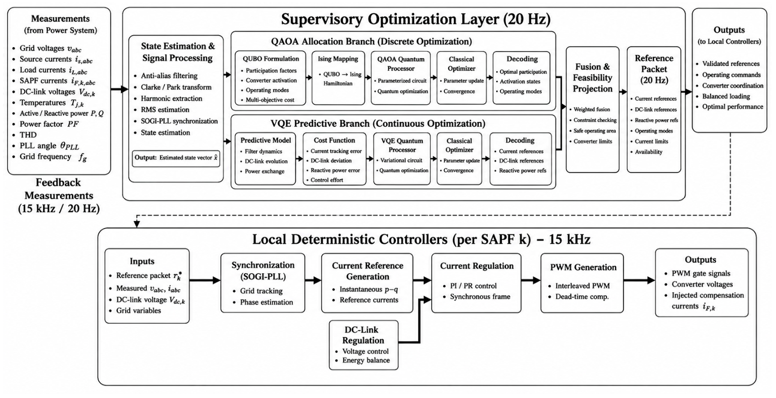
Figure 3 (
Appendix A) presents the complete hierarchical control architecture of the proposed Distributed Quantum Multi-SAPF system. The workflow is organized into two coordinated control layers operating at different time scales. The supervisory optimization layer executes asynchronously at 20 Hz and determines the optimal operating conditions for the distributed converters, whereas the local deterministic controllers execute at 15 kHz and perform real-time regulation of the compensation currents. This multi-rate organization separates computationally intensive optimization from fast electrical control, allowing advanced supervisory decision-making without compromising deterministic real-time operation.
The workflow begins with the measurement block, where all electrical variables required for control are acquired from the power system. These include the three-phase grid voltages, source currents, nonlinear load currents, SAPF currents, DC-link voltages, converter temperatures, active and reactive powers, power factor, current harmonic distortion, PLL angle, and grid frequency. These synchronized measurements provide a complete representation of the instantaneous operating condition of the distributed filtering system and form the input to the supervisory controller.
The measured signals are processed by the State Estimation and Signal Processing block. Anti-alias filtering removes measurement noise, Clarke and Park transformations convert the electrical variables into the synchronous reference frame, harmonic extraction isolates the distortion components, RMS estimation computes steady-state quantities, and the SOGI-PLL estimates the grid phase and frequency. The output is a compact estimated state vector that accurately describes the electrical state of the complete multi-SAPF system while reducing the dimensionality of the optimization problem.
The supervisory layer contains two complementary optimization stages. The QAOA branch addresses the discrete coordination problem by selecting a prevalidated operating profile from the encoded supervisory profile set. The four-bit representation determines discrete controller parameters such as the current loop time constant, DC-link energy loop gains, and current envelope. QAOA, therefore, answers the question of which admissible operating profile should be activated. The continuous participation vector is not decoded directly from these four QAOA bits; participation and current sharing belong to the subsequent continuous allocation/refinement and feasibility process.
After the discrete profile decision, the VQE/VQA-assisted predictive branch provides a bounded supervisory refinement. A continuous constrained problem is not passed directly to a finite-qubit VQE. Instead, bounded refinement variables are represented with finite resolution, their predictive costs define a finite dimensional Hermitian cost operator, and the selected candidate is deterministically decoded. In the present numerical study, this stage is implemented as a hybrid numerical supervisory refinement rather than execution on a physical quantum processor. Its output is advisory and is never applied directly as a PWM command.
The outputs of the two optimization branches are merged in the Fusion and Feasibility Projection block. Here, the discrete allocation decisions from the QAOA branch are combined with the continuous operating references generated by the VQE branch. The resulting solution is checked against converter current limits, Safe Operating Area constraints, DC-link voltage limits, and operating restrictions. Only physically feasible operating points are accepted, guaranteeing that every supervisory command can be safely implemented by the local controllers.
The validated supervisory solution is organized into a reference packet, which is updated every 50 ms (20 Hz). This packet contains the current references, DC-link voltage references, reactive power references, operating modes, current limits, and converter availability information for each SAPF module. The reference packet represents the interface between the supervisory optimization layer and the deterministic control layer.
The lower portion of the figure illustrates the local deterministic controller, which executes independently for every SAPF converter at 15 kHz. Each controller receives the supervisory reference packet together with locally measured voltages, currents, DC-link voltage, and grid variables. The controller first performs SOGI-PLL synchronization, estimating the grid angle required for synchronous reference frame control.
The synchronized variables are supplied to the current reference generation block, where the instantaneous - theory computes the compensation current references assigned to the corresponding SAPF converter. The DC-link regulation block simultaneously maintains constant capacitor energy by adjusting the active-current component needed to compensate converter losses. These two outer loops generate the final current references for the inner current controller.
The current regulation block constitutes the high-bandwidth inner control loop. Operating in the synchronous reference frame, PI or PR regulators accurately track the reference currents and generate the converter voltage commands. Their outputs are supplied to the PWM generation block, which performs interleaved PWM modulation with dead time compensation to generate the IGBT gate signals.
Finally, the deterministic controller produces the converter voltages and compensation currents injected into the Point of Common Coupling. These currents cancel the harmonic and reactive components drawn by the nonlinear load, thereby restoring nearly sinusoidal source currents and a power factor close to unity.
The dashed feedback path highlights the closed-loop cyber–physical operation of the proposed architecture. The compensation currents continuously modify the electrical state of the network, new measurements are acquired, and the supervisory optimization is repeated every 20 Hz, while the deterministic controller continues regulating the converter every 15 kHz. Consequently, 750 deterministic control cycles are executed between two consecutive supervisory updates. This hierarchical arrangement enables computationally intensive quantum-assisted optimization to improve converter coordination while preserving the fast dynamic response, stability, and deterministic behaviour required for industrial active power filters.