1. Introduction
The rapid growth of small unmanned aerial vehicles (UAVs), especially mini- and micro-class rotary-wing drones, has introduced new challenges for airspace security, critical infrastructure protection, and military operations. Their low cost, easy accessibility, small physical size, and ability to fly at low altitude make them difficult targets for conventional surveillance and interception systems [
1,
2]. Commercial drones also rely heavily on radio-frequency (RF) links for command-control, telemetry, navigation support, and real-time video transmission. In many consumer platforms, these links are commonly implemented around the 2.45 GHz and 5.8 GHz industrial, scientific, and medical (ISM) bands, which are also widely used by Wi-Fi-based communication systems [
3,
4]. Therefore, RF link suppression has become a practical non-kinetic approach for limiting the operation of unauthorized drones.
Recent studies have shown that SDR-based systems can provide flexible and low-cost platforms for RF jamming, spoofing, and wireless-security experimentation. In Wi-Fi systems, SDR-based jamming implementations have been used to evaluate different jamming waveforms and attack strategies, with Gaussian noise jamming and channel-hopping approaches showing strong degradation effects on IEEE 802.11 links [
5]. In the counter-drone context, SDR-based jamming and spoofing have also been experimentally investigated for radio-control, geolocation, and video-transmission links [
3]. These studies confirm the practical relevance of SDR-based RF countermeasures. However, they mainly focus on waveform generation, jamming strategy, or system-level neutralization, while the antenna is often treated as a supporting component rather than as a primary design contribution.
For directional RF link suppression, the transmitting antenna is a critical subsystem because it determines the effective radiated power density, beam coverage, and undesired radiation toward surrounding systems. A suitable counter-drone antenna should therefore provide dual-band operation at the relevant ISM bands, adequate impedance matching, high gain, directional radiation, and compatibility with compact SDR-based transmitter architectures. Conventional microstrip patch antennas are attractive due to their low profile, low cost, and ease of fabrication; however, they generally suffer from narrow impedance bandwidth and limited gain [
6,
7]. Several dual-band microstrip antennas have been reported for Wi-Fi/WLAN applications using slot-loaded patches, U-shaped slots, or multilayer configurations [
6,
7,
8]. Although these designs can operate around the 2.4 GHz and 5 GHz bands, they are mostly intended for wireless communication terminals and generally do not address the high-gain directional radiation requirements of RF link suppression systems.
Stacked patch structures have been widely used to improve bandwidth, support multi-resonant operation, and realize compact dual-frequency antenna designs. Single-feed dual-frequency stacked patch antennas have been demonstrated for GPS/WLAN applications, and asymmetric U-slot stacked patch designs have also been reported for dual-band circular polarization [
9,
10]. More recent studies have further shown that stacked patch and parasitic patch configurations can provide high gain and stable radiation performance in 5G and base-station-oriented applications [
11,
12]. These works confirm the effectiveness of stacked and parasitic radiating structures for improving antenna performance. Nevertheless, their target applications, operating bands, feeding requirements, and validation scenarios are different from those required for counter-drone RF link suppression.
Frequency selective surfaces (FSSs), artificial magnetic conductors, and partially reflective surfaces have also been extensively investigated for antenna gain enhancement and beam shaping. In particular, FSS reflectors can improve radiation performance by controlling the reflection phase and enabling constructive field superposition between the source antenna and the reflective/superstrate layer [
13,
14]. A closely related study proposed a dual-band ISM antenna with an FSS layer and reported gain enhancement at both 2.45 GHz and 5.8 GHz [
13]. Another dual-band printed antenna integrated with an FSS reflector achieved improved radiation performance for WLAN/Wi-Fi applications [
14]. Although these studies are important from an antenna engineering perspective, they remain mainly focused on wireless communication applications and conventional antenna characterization. They do not demonstrate the fabricated antenna in an SDR-based counter-drone RF link suppression scenario.
From the above literature, it is clear that dual-band microstrip antennas, stacked patch configurations, FSS-based gain enhancement, and SDR-based jamming have each been studied separately. However, these research directions are generally addressed from different perspectives. Antenna-oriented studies typically focus on impedance and radiation characteristics, whereas SDR-based counter-UAS studies primarily emphasize waveform generation, interference strategies, or link disruption and generally treat the transmitting antenna as a supporting component. In particular, there remains a practical gap for a single-fed dual-band RF front end that is developed from electromagnetic design and fabrication through impedance validation and subsequently evaluated, as part of the same SDR-based platform, against airborne communication links at both operating bands.
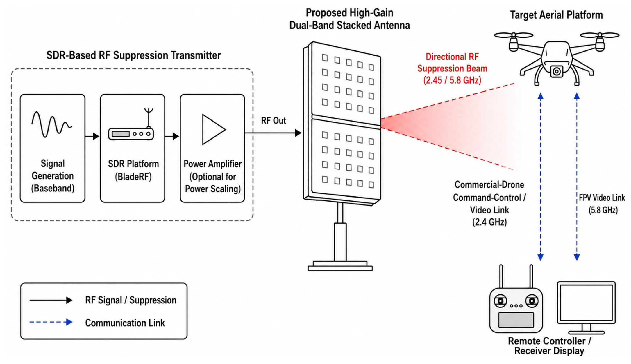
To address this gap, this paper presents a single-fed dual-band stacked antenna for directional counter-drone RF link suppression at the 2.45 GHz and 5.8 GHz ISM bands. Unlike previous studies that generally address dual-band antenna development and SDR-based RF interference generation as separate problems, this work establishes an integrated antenna–SDR proof-of-function framework in which the fabricated antenna is directly connected to a low-power SDR platform and evaluated against airborne communication links at both operating bands. The proposed configuration integrates a dual-band source antenna, a partial ground structure, a metallic reflector, two circular parasitic-resonator layers, and an FSS panel within an air-spaced multilayer architecture. The contribution is not attributed to any of these established loading techniques individually; rather, it lies in their coordinated use within a single-feed dual-band architecture and in carrying the resulting RF front end from electromagnetic design to fabrication, impedance validation, SDR integration, and application-level testing. The antenna is optimized through full-wave electromagnetic simulations and subsequently fabricated using Rogers RT 5880 (Rogers Corporation, Chandler, AZ, USA) substrates. The prototype is experimentally characterized through reflection-coefficient, gain, and far-field radiation-pattern measurements and then integrated with a BladeRF SDR platform for application-level proof-of-function validation. At 2.4 GHz, commercial-drone video and command-control links are evaluated through application-level functional tests, whereas the upper operating band is assessed using a 5.8 GHz FPV video link, for which visible video degradation is observed. The 2.4 GHz commercial-drone video test and the 5.8 GHz FPV video test employ the same open-field antenna-to-target geometry, whereas the 2.4 GHz command-control experiment is conducted separately. The overall concept of the proposed RF link-suppression setup is shown in
Figure 1.
2. Design Objectives and Optimization Methodology
The proposed antenna was designed for directional operation at the 2.45 GHz and 5.8 GHz ISM bands, which are commonly used by commercial drone communication links. The principal design targets were defined as dual-band impedance matching with S11 < −10 dB, a simulated realized gain of approximately 10 dBi or higher, a half-power beamwidth below 60°, and broadside radiation at both operating frequencies. A single coaxial probe was selected to excite both bands without requiring a power divider, hybrid coupler, or multi-port feeding network.
The antenna was developed through a sequential full-wave optimization process. The procedure began with a single-fed dual-band source antenna. The ground-plane configuration was then varied through three models, after which the reflector dimensions and reflector-to-source spacing were optimized. Two circular parasitic-resonator layers were subsequently introduced, followed by optimization of their positions and interlayer separation. Finally, the FSS panel was added above the resonator layers, and its vertical separation was adjusted to obtain the final hybrid configuration.
At each stage, only the parameter or structural element under investigation was varied while the remaining parameters were kept unchanged. The candidate configurations were evaluated in terms of impedance bandwidth, realized gain, half-power beamwidth, side-lobe level, and main-beam direction at 2.45 GHz and 5.8 GHz. A configuration was retained only when it improved the targeted characteristic without causing unacceptable degradation at the other operating band. The final design was therefore selected from the combined dual-band response rather than from the deepest individual resonance or the highest gain at a single frequency.
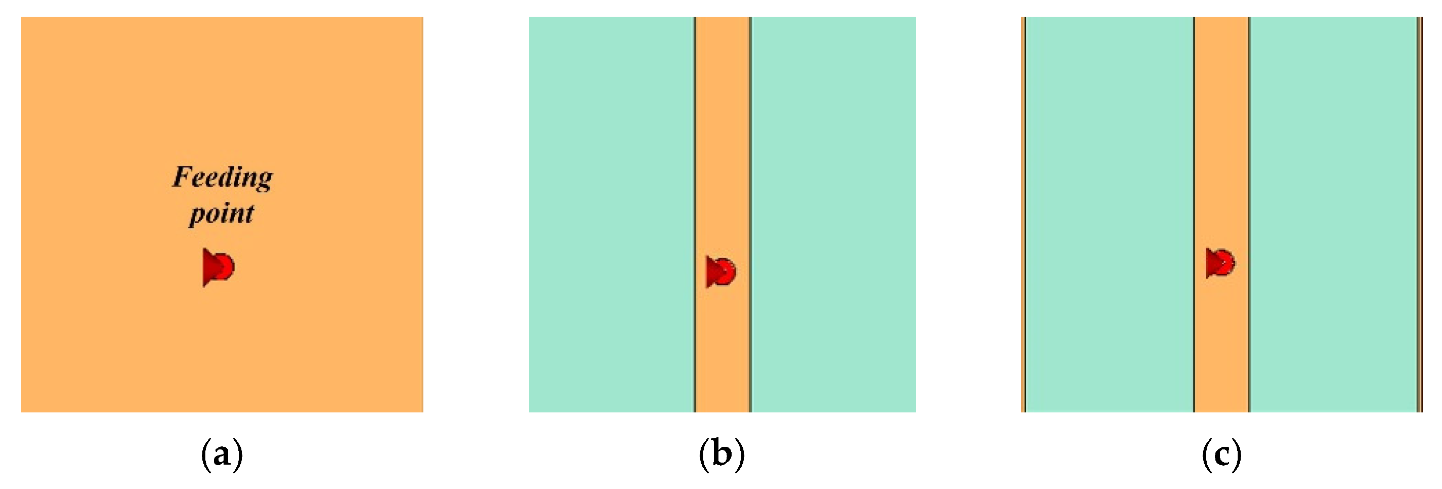
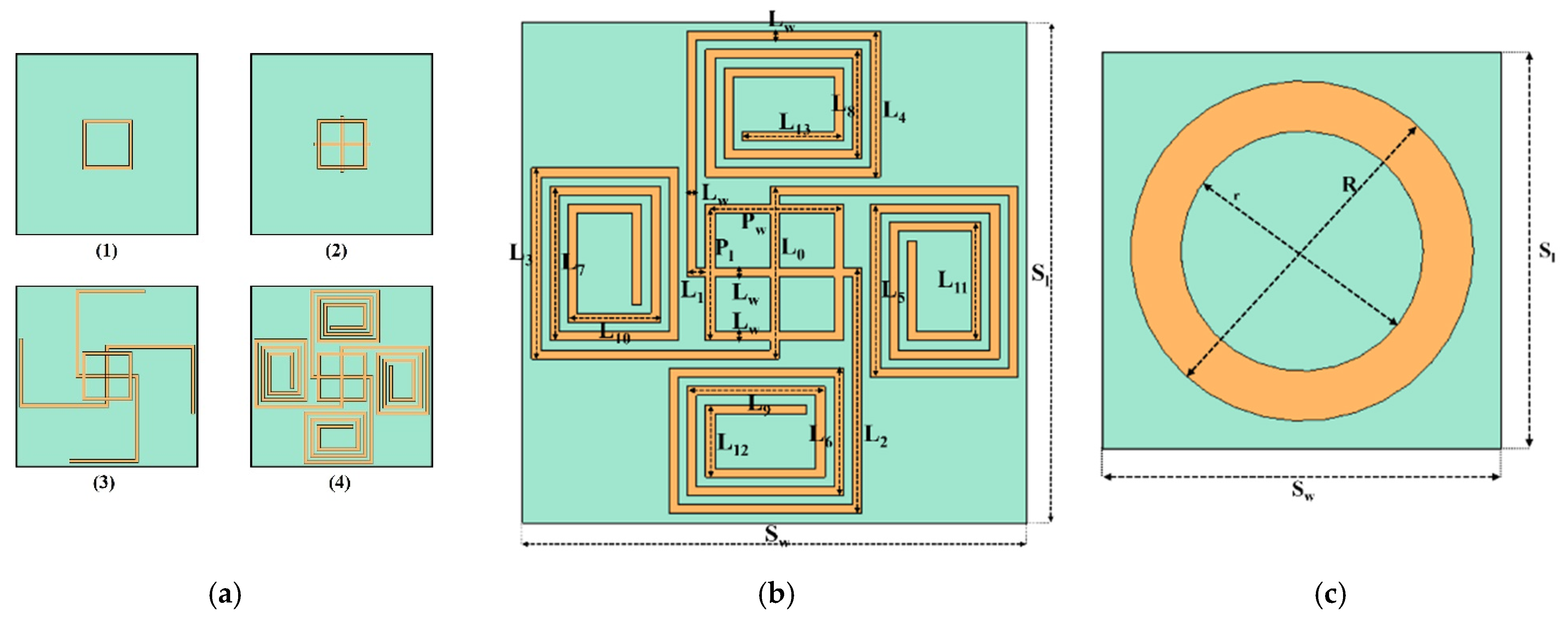
All electromagnetic analyses were performed using CST Studio Suite 2022. The finite antenna configurations, including the source antenna, reflector, parasitic-resonator layers, and finite FSS panel, were analyzed over 1–7 GHz using the time-domain solver. The standalone FSS was evaluated separately over the same frequency range using the frequency-domain solver with a tetrahedral mesh, unit-cell boundaries in the transverse directions, and two Floquet modes. This separate unit-cell analysis was used to identify the spectral response of the periodic FSS structure before its integration with the finite antenna model. The selected FSS geometry was subsequently implemented as the finite 7 × 7 panel described in
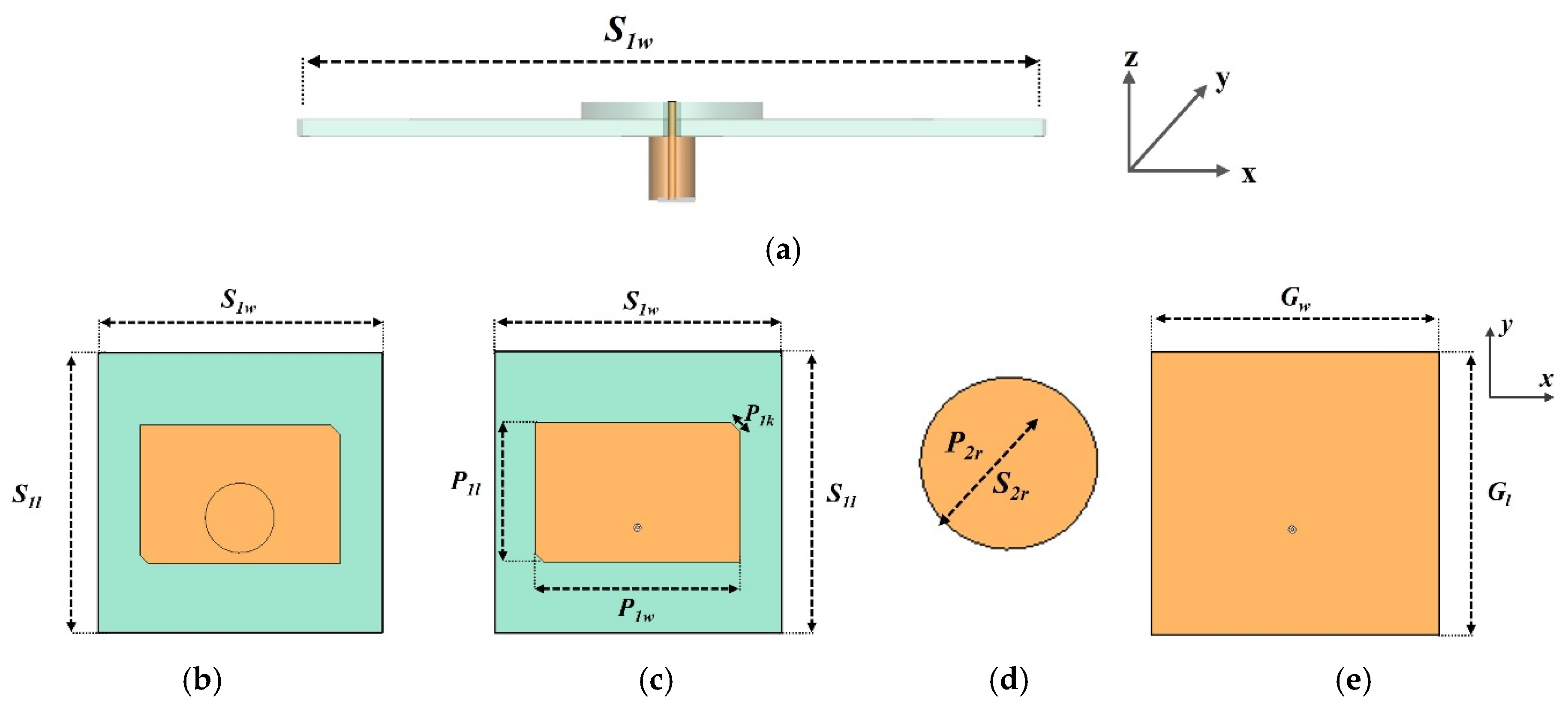
Section 3.3, while each circular parasitic-resonator layer was represented by the corresponding 23 × 23 array. Throughout the staged optimization, the material definitions and geometrical parameters not under investigation were kept unchanged so that the incremental effect of each loading stage could be assessed using a common set of antenna-performance metrics. The resulting geometry and physical arrangement are presented in
Section 3, whereas the effects of the successive optimization stages are examined in
Section 4. The optimized antenna was subsequently fabricated for experimental impedance and far-field characterization and integrated with an SDR platform for complementary application-level functional tests at the two operating bands.
4. Parametric Study and Optimization
A staged full-wave parametric study was conducted to verify the geometrical choices of the proposed antenna and to identify the contribution of each passive loading stage. The optimization sequence also provides a structural ablation of the architecture, progressing from the PGS-loaded source antenna to the reflector-backed reference configuration, then to the double-resonator-loaded configuration, and finally to the complete resonator–FSS hybrid structure. During each optimization step, the parameter or structural element under investigation was varied while the remaining antenna parameters were kept unchanged. The same evaluation criteria were applied at each stage, including the simulated reflection coefficient, realized gain, half-power beamwidth, side-lobe level, and main-beam direction at 2.45 GHz and 5.8 GHz. Unless otherwise stated, the impedance bandwidths reported in this section correspond to the frequency range satisfying S
11 < −10 dB. The optimized geometrical parameters of the proposed DBSA are summarized in
Table 1.
4.1. Partial Ground Structure and Reflector Optimization
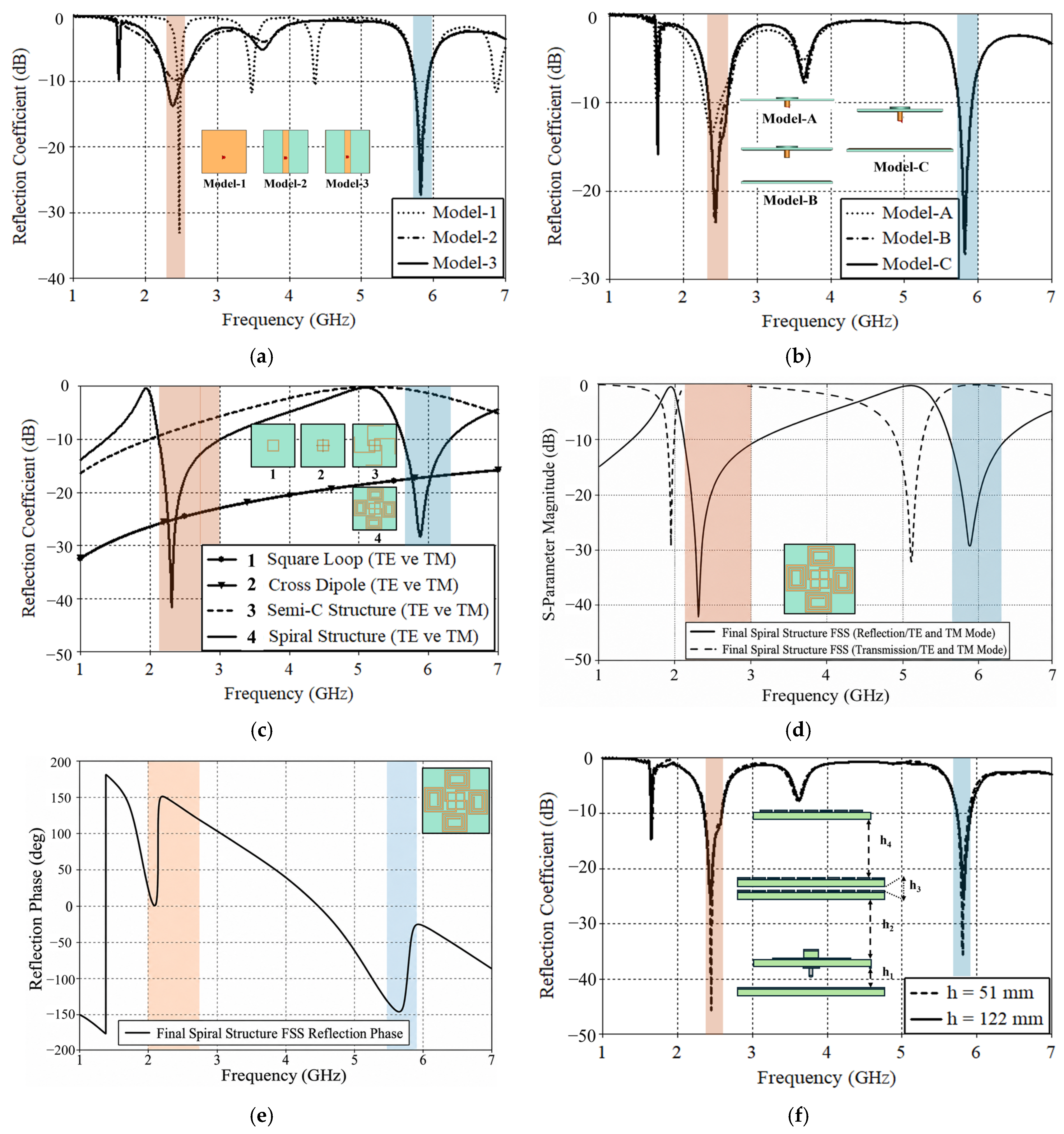
The first optimization stage concerns the ground-plane configuration of the single-fed source antenna. Model-1 employs a conventional full ground plane. At the lower band, this configuration produces a deep resonance of −33.03 dB at 2.47 GHz; however, the corresponding impedance bandwidth is limited to 49 MHz. At the upper band, Model-1 provides a resonance of −20.33 dB at 5.82 GHz with a bandwidth of 168 MHz. These results show that a deep resonance alone does not ensure sufficient impedance bandwidth, particularly at the lower operating band.
In Model-2, most of the ground metallization is removed while a narrow central strip is retained below the coaxial feed. This modification changes the return-current path and increases the upper-band impedance bandwidth to 191 MHz, with a minimum S11 of −26.87 dB. However, the lower-band response remains slightly above the matching criterion, with S11 = −9.84 dB. The central strip therefore provides effective tuning at the upper band but does not produce balanced dual-band matching.
Model-3 introduces two additional symmetric strips along the outer edges of the partial ground plane. The resulting response is consistent with an additional distributed capacitive contribution that compensates for the input reactance introduced by the central strip. With this modification, the lower-band reflection coefficient improves to −13.75 dB. The lower- and upper-band impedance bandwidths become 212 MHz and 191 MHz, respectively. Based on this comparison, Model-3 was selected as the final partial ground structure. The simulated reflection-coefficient responses of the three models are compared in
Figure 6a.
Although Model-3 satisfies the dual-band impedance-matching requirement, the extensive ground truncation reduces the shielding effect of the ground plane. The resulting configuration exhibits increased backward radiation, a wider radiation pattern, and an undesired beam deviation at the upper operating band. A reflector plane was therefore introduced behind the source antenna.
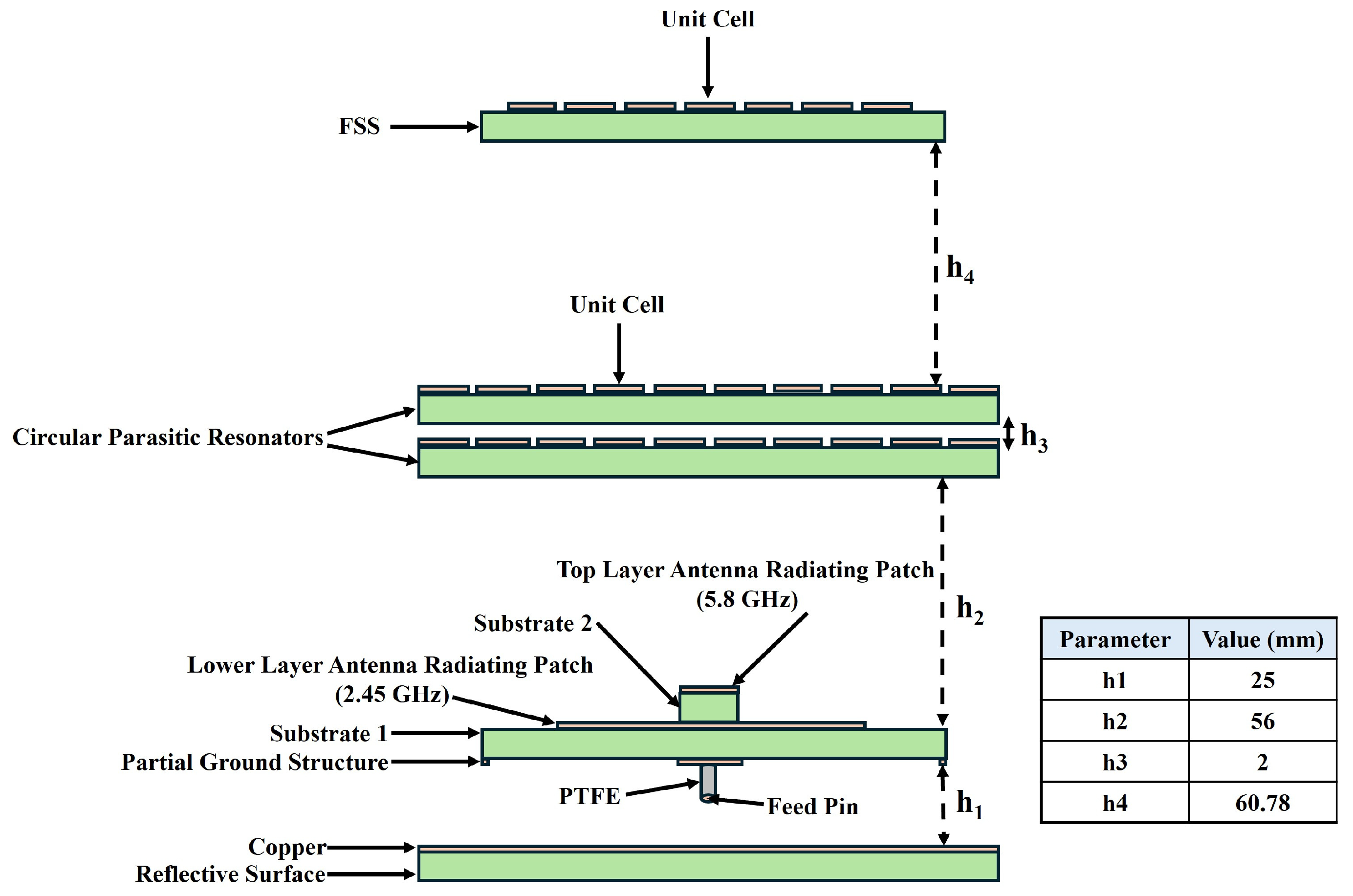
The initial reflector spacing was estimated from the quarter-wavelength condition and was subsequently optimized through a full-wave parametric sweep. The theoretical quarter-wavelength distances are approximately 30.6 mm at 2.45 GHz and 12.9 mm at 5.8 GHz. Since a single separation cannot satisfy the ideal phase condition at both frequencies, h1 was selected as a dual-band compromise.
Three reflector configurations were evaluated. Model-A represents the PGS-loaded source antenna without a reflector. Model-B uses a reflector with lateral dimensions equal to those of the source antenna, whereas Model-C employs the final 100 mm × 100 mm reflector. The addition of the Model-B reflector improves the lower-band reflection coefficient to −23.74 dB and increases its impedance bandwidth to 233 MHz. Increasing the reflector aperture in Model-C further extends the lower-band bandwidth to 254 MHz while maintaining an upper-band bandwidth of approximately 185 MHz. Model-C also provides simulated realized gains of 8.4 dBi and 7.9 dBi at 2.45 GHz and 5.8 GHz, respectively. The reflection-coefficient responses of the reflector configurations are shown in
Figure 6b. Model-C was therefore selected as the reflector-backed reference configuration for the subsequent passive-loading stages.
4.2. Direct FSS Loading and Parasitic Resonator Optimization
Before integration with the antenna, the standalone response of the FSS unit cell was evaluated using periodic boundary conditions and Floquet-port excitation. All successive unit-cell geometries were evaluated using the same periodic-analysis configuration so that the effect of the geometrical modifications could be compared independently of the finite antenna structure. As shown in
Figure 6c, the successive geometrical modifications shift and deepen the two reflection minima. The final spiral-loaded configuration provides low-reflection regions covering approximately 2.1–3.0 GHz and 5.6–6.3 GHz, with minima of approximately −41.6 dB and −28.3 dB at 2.30 GHz and 5.87 GHz, respectively. The corresponding reflection and transmission magnitudes of the final spiral unit cell are presented in
Figure 6d. The transmission response complements the reflection minima within the two frequency regions of interest, confirming the strongly frequency-selective behavior of the final unit cell.
Figure 6e further shows the reflection-phase response, which varies substantially with frequency across both operating regions and demonstrates that the FSS introduces a dispersive phase response in addition to its magnitude response. This standalone analysis was used only as a spectral screening step to identify unit-cell responses overlapping the two antenna operating bands; the contribution of the FSS to the complete DBSA was subsequently evaluated using the finite full-antenna model.
Following the standalone unit-cell evaluation, the FSS was initially positioned directly above the reflector-backed source antenna. Separation distances of approximately 122 mm and 51 mm were considered as initial values associated with the free-space wavelengths at 2.45 GHz and 5.8 GHz, respectively. These distances were used as starting points for the full-antenna analysis rather than as fixed optimum conditions. Direct FSS loading did not provide a single separation that maintained a balanced response at both operating bands. The lower-band-based placement preserved the impedance response around 2.45 GHz but degraded the upper-band radiation characteristics. Conversely, the upper-band-based placement adversely affected the lower-band response. The corresponding reflection-coefficient variations are presented in
Figure 6f.
To obtain a more balanced dual-band configuration, two circular parasitic-resonator layers were subsequently inserted between the source antenna and the FSS. The first resonator layer was positioned at h2 = 56 mm above the source-antenna reference plane, and the interlayer separation was set to h3 = 2 mm. The double-layer resonator configuration increased the simulated realized gain from 8.4 to 9.5 dBi at 2.45 GHz and from 7.9 to 12.1 dBi at 5.8 GHz. The corresponding half-power beamwidths were reduced to approximately 57.5° and 32.2°, respectively. However, an approximately 8 dB deterioration was observed in the upper-band side-lobe level. Therefore, the resonator-only configuration was not selected as the final design.
4.3. FSS Position and Hybrid Configuration
In the final optimization stage, the FSS was positioned above the second circular parasitic resonator layer. The separation h4 was varied while the source antenna, reflector, and two resonator layers were kept unchanged. A final separation of h4 = 60.78 mm was selected because it provided the most balanced response in terms of dual-band matching, realized gain, beamwidth, and side-lobe suppression.
With the final resonator–FSS loading, the simulated reflection coefficients at 2.45 GHz and 5.8 GHz are −22.86 dB and −16.47 dB, respectively. The simulated realized gains increase to 10 dBi at the lower band and 12.5 dBi at the upper band. At 2.45 GHz, the half-power beamwidths are 58° and 54.1° in the two principal planes. At 5.8 GHz, the corresponding values are reduced to 30.7° and 30.8°. The simulated side-lobe levels are −15.5 dB and −13.4 dB at the lower and upper bands, respectively.
The final FSS layer therefore provides a moderate additional gain improvement compared with the resonator-only configuration, while its main contribution is the recovery of the upper-band side-lobe performance and the preservation of the narrow broadside beam. Accordingly, the FSS should not be interpreted as an isolated gain-enhancement element in the present architecture; its contribution is assessed relative to the resonator-only reference configuration as part of the complete coupled multilayer system. On this basis, the complete reflector–resonator–FSS configuration was selected as the final DBSA design. The final simulated radiation characteristics are presented in
Section 4.4, whereas the fabricated prototype and experimental impedance and far-field validation are presented in
Section 5.
4.4. Simulated Radiation Characteristics
The radiation performance of the final DBSA was evaluated at the two operating frequencies using the optimized reflector, parasitic-resonator, and FSS configuration. The results presented in this subsection correspond to full-wave simulations and provide the numerical reference for the experimental far-field characterization presented in
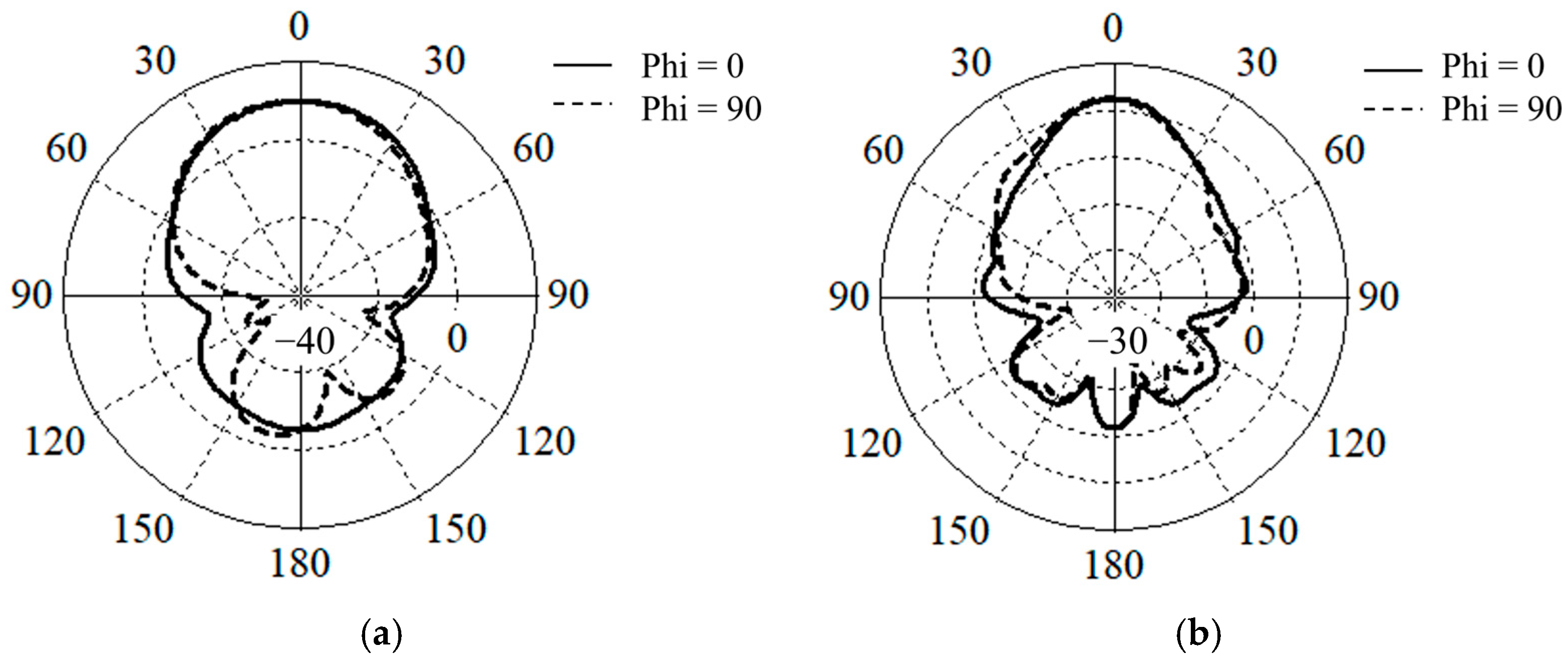
Section 5. At 2.45 GHz, the proposed antenna produces a broadside directional pattern with a simulated realized gain of 10 dBi. The half-power beamwidths are 58.0° and 54.1° in the principal E- and H-planes, respectively. The maximum simulated side-lobe level is approximately −15.5 dB relative to the main beam. These results indicate that the lower-band radiation remains sufficiently directional despite the comparatively larger electrical wavelength. At 5.8 GHz, the electrically larger aperture produces a narrower radiation pattern and a higher simulated realized gain of 12.5 dBi. The corresponding half-power beamwidths are 30.7° and 30.8° in the E- and H-planes, respectively. The maximum simulated side-lobe level is approximately −13.4 dB. The nearly equal beamwidths in the two principal planes indicate a comparatively balanced broadside beam at the upper operating band. The simulated normalized radiation patterns at 2.45 and 5.8 GHz are shown in
Figure 7.
The final configuration therefore provides a higher simulated gain and a narrower beam at 5.8 GHz while maintaining directional radiation at 2.45 GHz. Compared with the reflector-backed source antenna, the parasitic-resonator and FSS loading results in improved simulated broadside gain. The contribution of the FSS is particularly evident in the upper-band side-lobe response, where the deterioration introduced by the resonator-only configuration is reduced. These simulated results provide the reference radiation characteristics for the subsequent experimental validation of the fabricated antenna presented in
Section 5.
5. Prototype Fabrication and Antenna Validation
The individual layers of the proposed DBSA were fabricated using Rogers RT 5880 substrates with the material properties and geometrical dimensions specified in
Section 3. The source-antenna layers, partial ground structure, metallic reflector, circular parasitic-resonator arrays, and FSS panel were manufactured separately. The fabricated FSS layer retained the 7 × 7 unit-cell arrangement, whereas each circular parasitic-resonator layer retained the 23 × 23 annular-element arrangement defined in the electromagnetic model. The passive-layer laminates were extended to 104 × 104 mm
2 only to provide mechanical margins and accommodate the corner mounting holes; the periodic element counts and spacings were not altered. The fabricated layers were then mechanically aligned and assembled according to the optimized vertical separations
h1–
h4. Particular attention was given to the alignment of the coaxial probe, the relative position of the two radiating patches, and the air gaps between the passive layers, since small deviations in these parameters can affect the impedance response of the multilayer antenna.
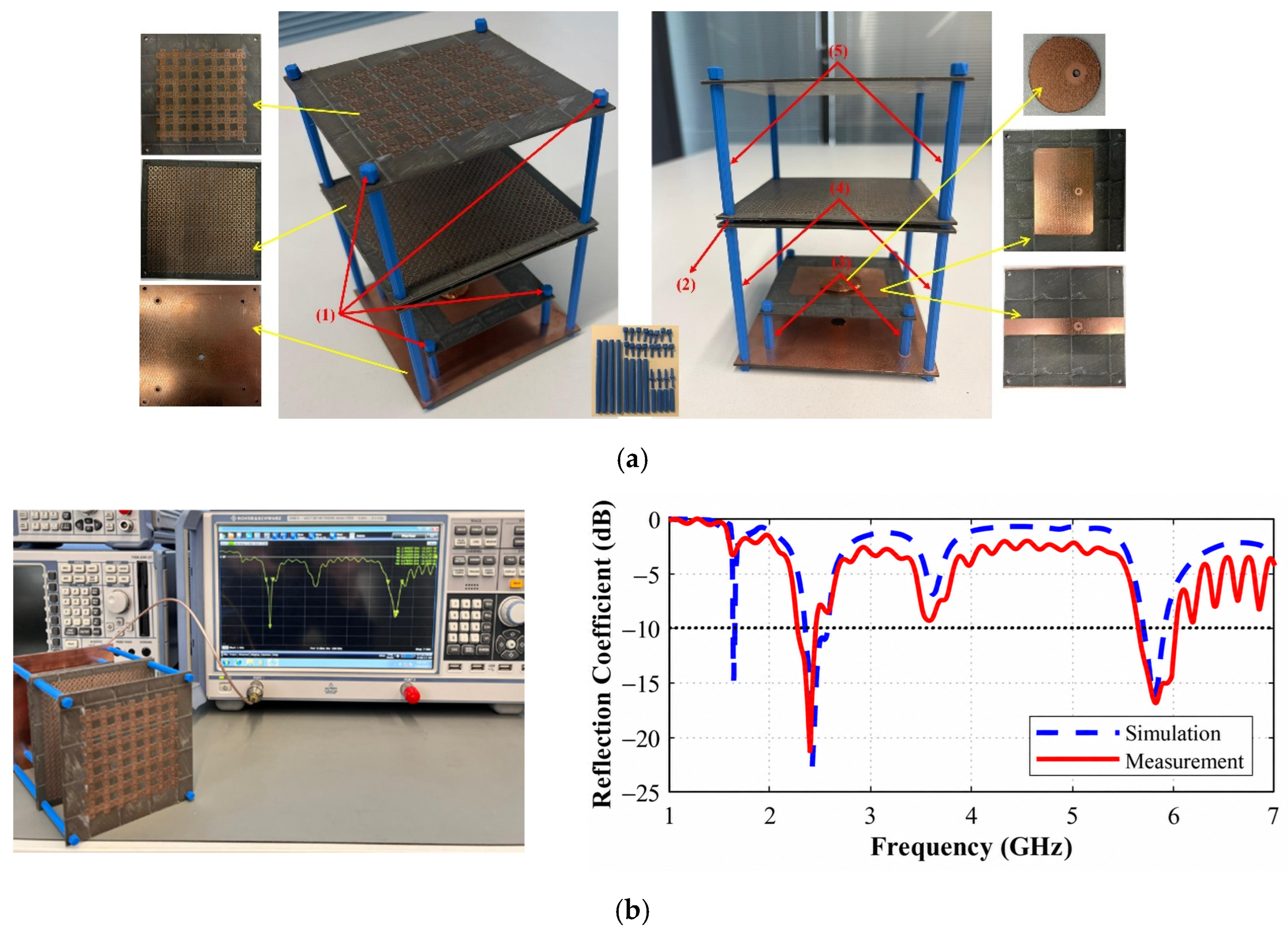
The reflection coefficient of the fabricated prototype was measured using a Rohde & Schwarz ZNB8 vector network analyzer (Rohde & Schwarz, Munich, Germany). Before connecting the antenna, a one-port open-short-load calibration was performed at the end of the measurement cable, thereby establishing the calibration reference plane at the antenna SMA connector. The antenna was then connected to the calibrated measurement port through its SMA interface, and the reflection coefficient was recorded over a frequency range covering both ISM operating bands. The fabricated components, assembled antenna, VNA measurement setup, and simulated–measured comparison are presented together in
Figure 8.
The simulated antenna satisfies the −10 dB impedance criterion from 2.36 to 2.57 GHz in the lower band and from 5.71 to 5.91 GHz in the upper band. The fabricated antenna exhibits measured impedance bands of 2.28–2.52 GHz and 5.60–5.92 GHz, respectively. Both measured bands cover the intended 2.45 GHz and 5.8 GHz operating frequencies.
A reasonable agreement is observed between the simulated and measured reflection-coefficient responses, although moderate frequency shifts and bandwidth differences are present. The measured lower band is shifted slightly toward lower frequencies, whereas the measured upper band is broader than its simulated counterpart. These discrepancies may arise from fabrication tolerances, small deviations in the coaxial-probe position, uncertainties in the dielectric and conductor properties, soldering and connector effects at the SMA transition, variations in the air gaps introduced during mechanical assembly, and local dielectric loading associated with the 3D-printed PLA support elements [
15]. The influence of the PLA spacers may be more noticeable at 5.8 GHz because the upper-band response is more sensitive to small geometrical and dielectric perturbations; however, their isolated contribution was not independently quantified. Therefore, the measured deviations should be interpreted as the combined effect of the fabrication and assembly uncertainties rather than being attributed to a single source.
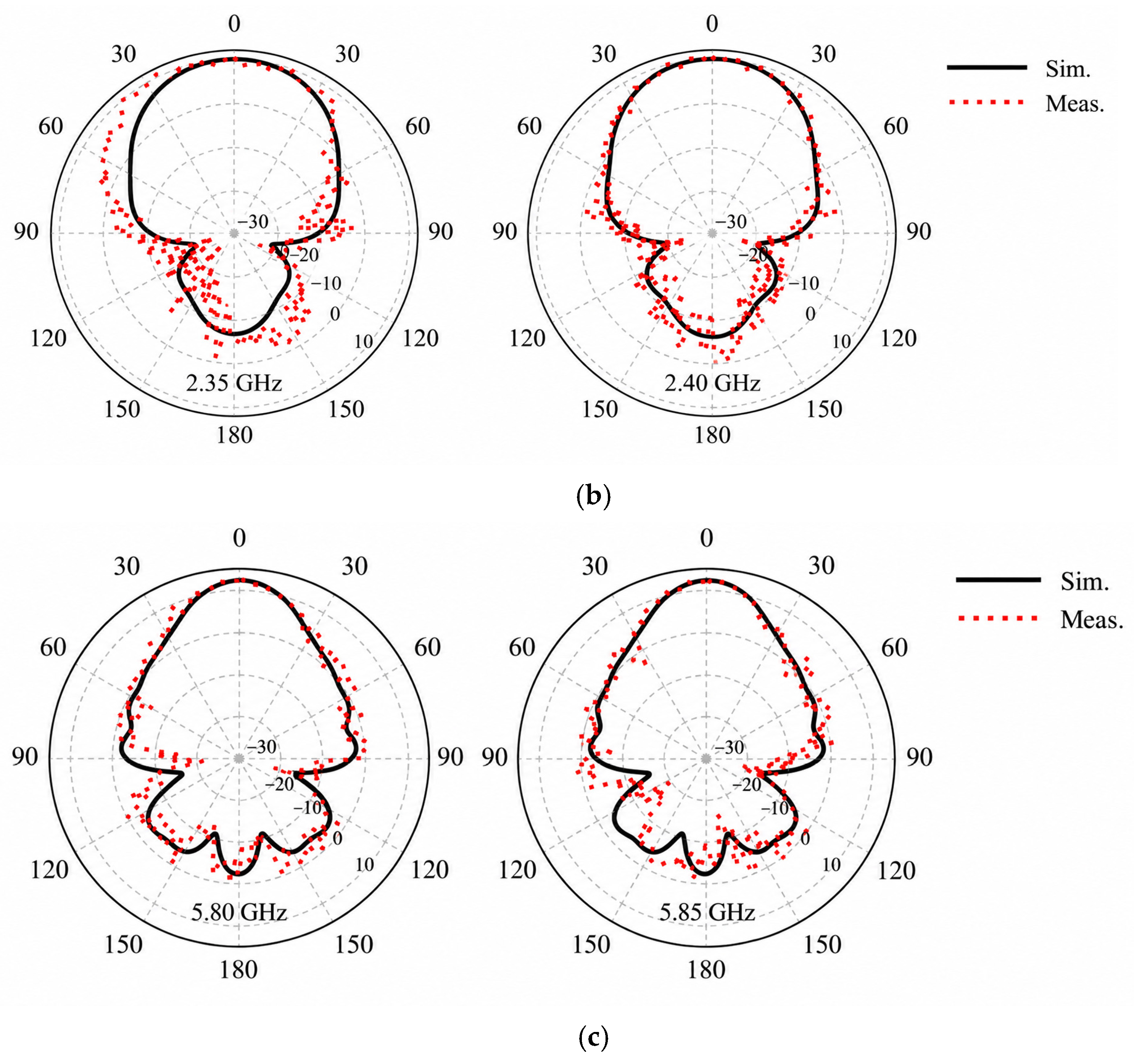
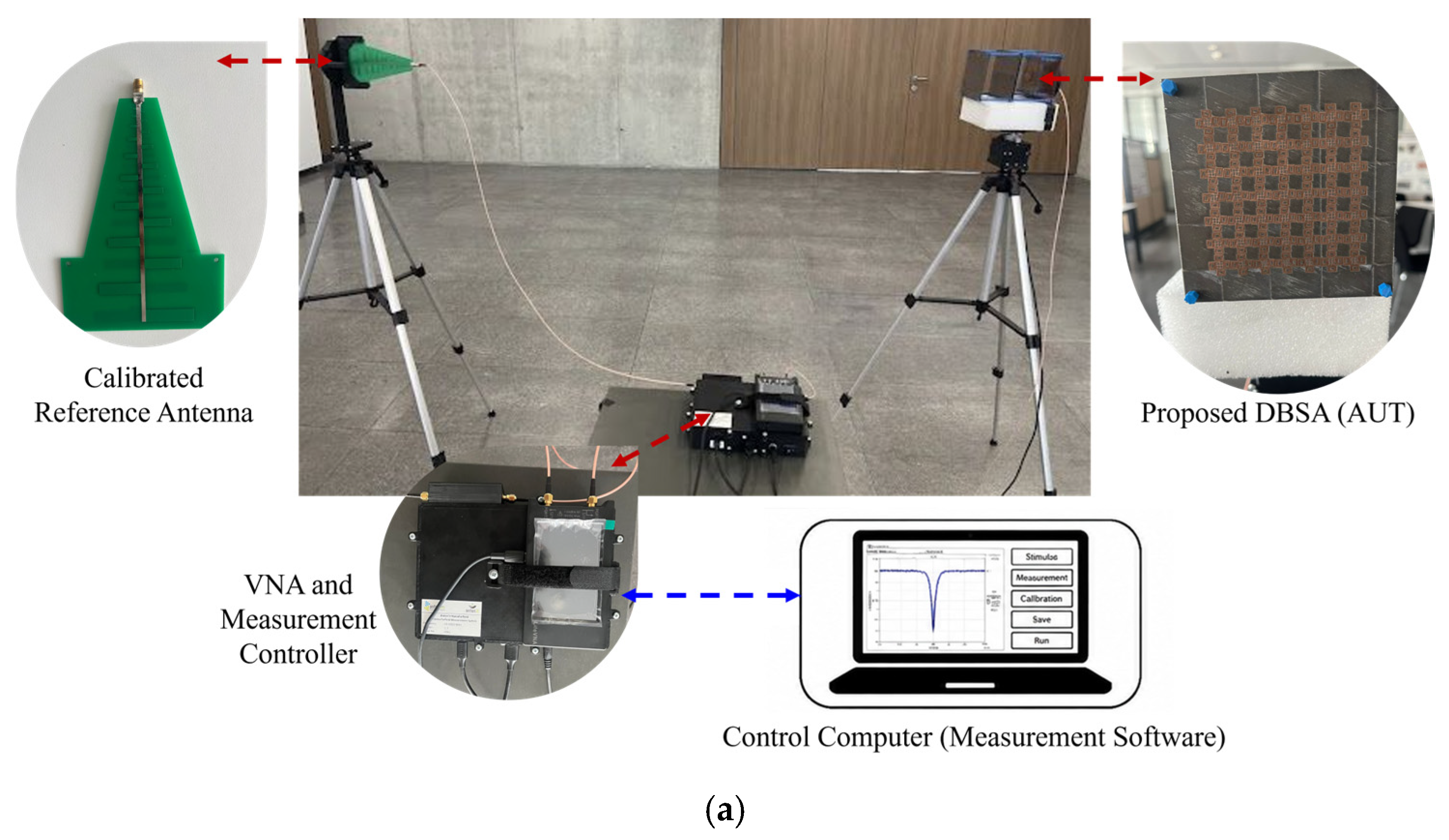
Following the impedance measurements, the far-field radiation performance of the fabricated DBSA was experimentally characterized using the setup shown in
Figure 9a. A calibrated reference antenna was first mounted to establish the measurement reference and was subsequently replaced by the proposed DBSA at the antenna-under-test position. The VNA and measurement controller were connected to a PC running the dedicated measurement software, which controlled the angular scan and recorded the radiation response. The measured radiation patterns were obtained for the φ = 0° co-polarized cut and were compared with the corresponding full-wave simulation results.
The measured gain values also show good agreement with the full-wave predictions over the evaluated frequency points within both operating bands. At 2.35, 2.40, and 2.45 GHz, the simulated gains were 9.92, 10.05, and 10.00 dBi, respectively, whereas the corresponding measured values were 9.37, 9.51, and 9.64 dBi. At the upper band, simulated gains of 12.50 and 12.40 dBi at 5.80 and 5.85 GHz were compared with measured values of 12.06 and 11.73 dBi, respectively. The absolute differences between simulation and measurement ranged from 0.36 to 0.67 dB across the evaluated frequencies.
As shown in
Figure 9b,c, the measured normalized patterns preserve the broadside directional behavior predicted by the simulations at both operating bands. Good agreement is observed particularly in the main-beam region, while larger deviations occur in the side-lobe and back-radiation regions. These differences are reasonably attributable to the combined effects of fabrication and assembly tolerances, antenna alignment, the measurement fixtures and cables, and residual scattering within the indoor measurement environment. Overall, the measured patterns experimentally confirm the directional radiation behavior of the fabricated DBSA in the φ = 0° co-polarized cut.
The experimental results therefore confirm both the dual-band impedance response and the directional radiation performance of the fabricated antenna. At the nominal operating frequencies, measured gains of 9.64 dBi at 2.45 GHz and 12.06 dBi at 5.80 GHz were obtained, compared with simulated values of 10.00 and 12.50 dBi, respectively. Additional measurements at 2.35, 2.40, and 5.85 GHz showed similarly consistent gain behavior, with the maximum simulation-to-measurement difference remaining below 0.7 dB across the evaluated frequency points. The measured φ = 0° co-polarized radiation patterns also retained the simulated broadside directional characteristics. The fabricated prototype is subsequently evaluated at the application level through the SDR-based proof-of-function tests described in
Section 6.
6. SDR-Based Proof-of-Function Testing
Following the impedance and far-field characterization described in
Section 5, the fabricated DBSA was integrated into an SDR-based RF link-suppression testbed to evaluate its application-level functionality. The experiments were conducted under indoor and open-field conditions using a BladeRF 2.0 Micro xA9 SDR platform, a laptop running GNU Radio, a low-loss 50 Ω coaxial transmission line, and the fabricated antenna. For the 2.4 GHz experiments, the target platform was a commercial Aden Evo drone operating between 2.416 and 2.475 GHz together with an FS-i6 FlySky controller operating between 2.408 and 2.475 GHz. For the upper-band experiment, a 5.8 GHz FPV video-transmitter and receiver link was used. The general test methodology was consistent with the SDR-based wideband-noise interference approaches reported for Wi-Fi and UAV communication links [
3,
5].
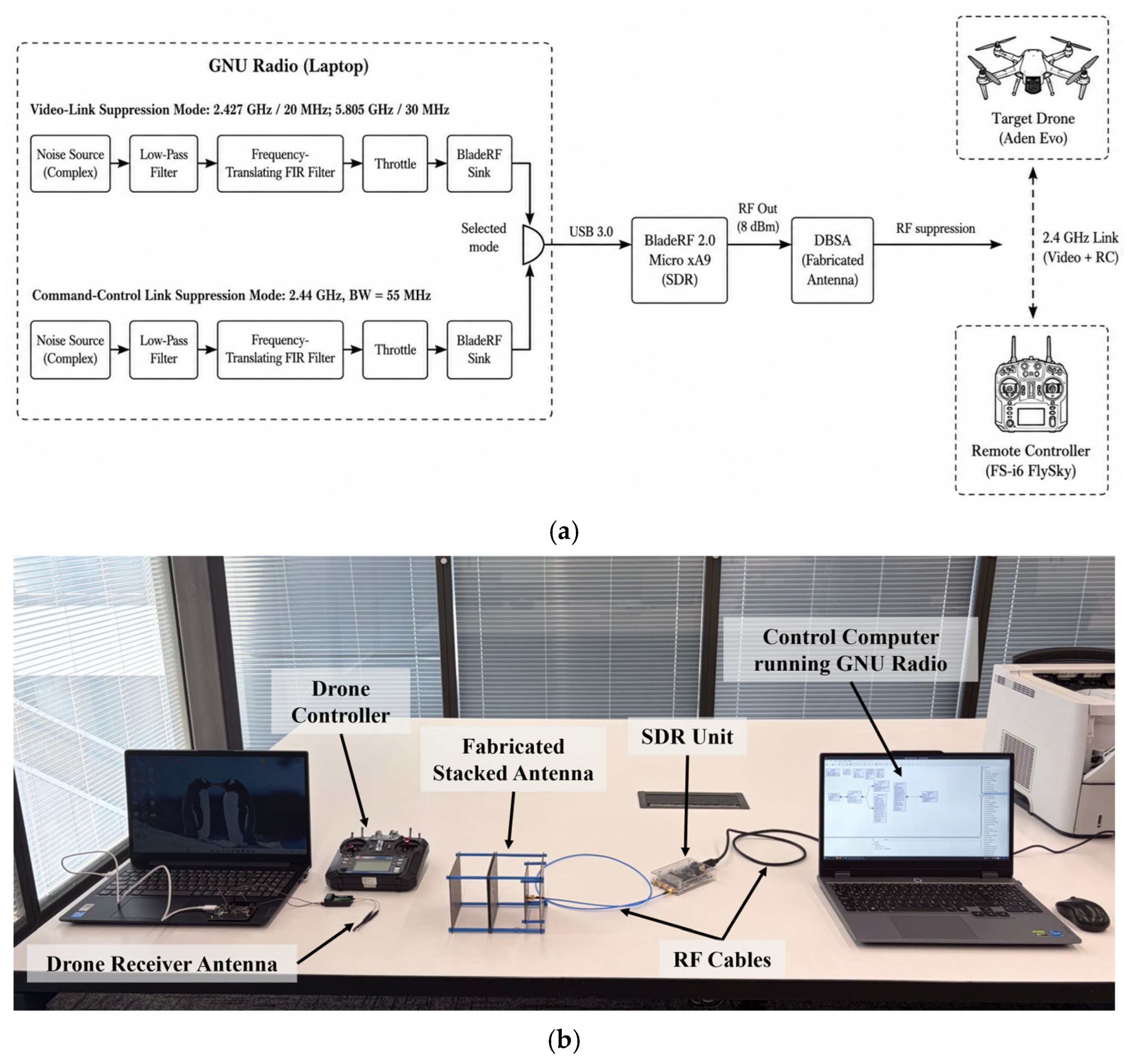
Two functional signal-generation modes were implemented in GNU Radio. The video-link mode was configured at 2.427 GHz with a transmission bandwidth of 20 MHz for the commercial-drone experiment and was subsequently reconfigured to a center frequency of 5.805 GHz with a bandwidth of 30 MHz for the FPV video-link experiment. The command-control mode generated a wider noise waveform centered at 2.44 GHz with a bandwidth of 55 MHz. The latter value was selected close to the 56 MHz RF-bandwidth capability of the BladeRF platform [
16] to cover a large portion of the frequency-hopping control band. In all configurations, the generated Gaussian-noise samples were filtered before transmission and delivered to the DBSA through the SDR RF output. No external power amplifier was used during the experiments. The RF output power was independently measured at the SDR output using a calibrated oscilloscope and was approximately 8 dBm (6.3 mW) under the reported configuration. This value corresponds to the SDR-output reference plane, before coaxial-cable and connector losses, and therefore does not represent either the power delivered to the antenna input or the system EIRP. The GNU Radio architecture and the physical interconnection used in the functional validation are shown in
Figure 10.
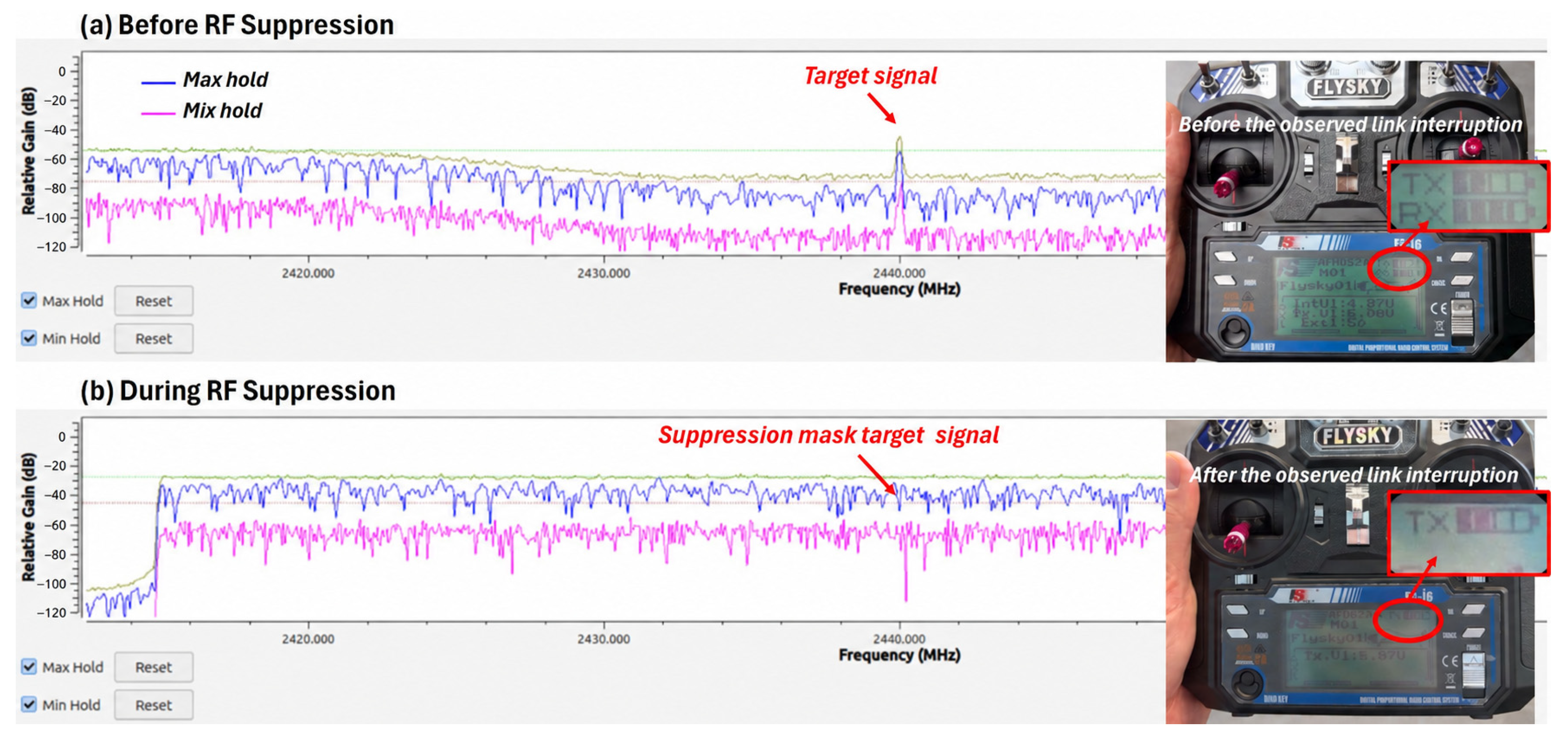
The first tests were performed in a controlled indoor environment at 2.4 GHz. Before activation of the wideband-noise transmission, the monitoring interface displayed an active communication component around 2.44 GHz at an approximate level of −40 dBm. After activation of the 55 MHz noise waveform, the monitored spectrum was dominated by a broadband region reaching approximately −30 dBm on the same interface. These displayed values were used only to observe the relative spectral change and were not treated as calibrated received-power measurements.
During the indoor test, the separation between the DBSA and the drone receiver was 2 m, whereas the controller was positioned approximately 40 m from the drone. When the SDR transmission was enabled, the receiver-side data indication on the controller ceased and a functional interruption of the command-control link was observed. The monitored spectral change and the corresponding controller status before and during RF suppression are presented in
Figure 11.
The open-field experiments were conducted within an approximately 5 km × 5 km controlled-access test area as part of an institutionally approved research activity. The experimental location was selected near the central portion of the area to maximize separation from its boundaries and to minimize unintended exposure of surrounding spectrum users. Because the 2.4 and 5.8 GHz ISM bands are widely shared, RF transmission was limited to the short intervals required for each functional observation. No external power amplifier was used, and the SDR output power was independently measured as approximately 8 dBm (6.3 mW) at the SDR-output reference plane, before coaxial-cable and connector losses. During transmission, the directional DBSA was pointed toward the designated airborne target. These procedural and technical precautions were adopted to limit unintended RF exposure outside the immediate experimental geometry. No exclusive spectrum access is implied by these test conditions.
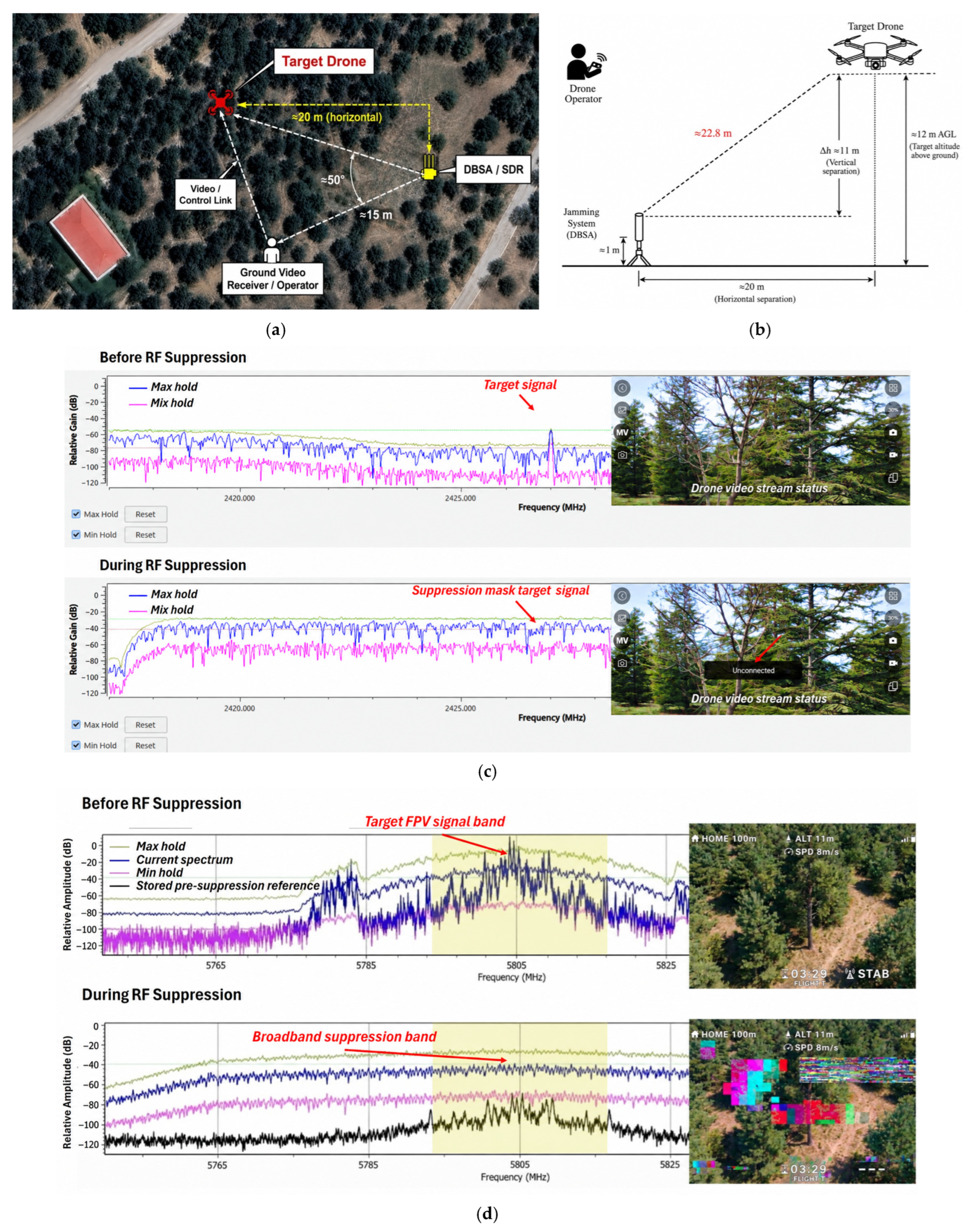
Open-field video-link experiments were subsequently conducted at both operating bands using the same test area and geometrical arrangement. The SDR platform and DBSA were installed on a fixed support approximately 1 m above ground level. In both video-link experiments, the horizontal separation between the DBSA and the airborne target was approximately 20 m, while the target altitude was approximately 12 m above ground level. The corresponding vertical separation was therefore approximately 11 m, resulting in a DBSA-to-target line-of-sight distance of approximately 22.8 m. Except for the target video-link hardware and the center frequency and bandwidth of the suppression waveform, the antenna position, pointing direction, target position, and propagation geometry were maintained between the two experiments. The DBSA was directed toward the airborne target. Based on the recorded field layout, the ground-based receiving endpoint used in each video-link experiment was positioned at approximately the same location, about 15 m from the DBSA and approximately 50° in azimuth from the DBSA-to-target boresight direction. The receiver was therefore outside the intended boresight direction of the directional antenna. However, the power of the wideband interference signal coupled to this ground-based receiver was not independently measured; consequently, residual off-axis coupling and associated receiver-front-end desensitization cannot be completely excluded from the observed video-link response.
In the 2.4 GHz commercial-drone video-link experiment, a 20 MHz broadband noise waveform centered at 2.427 GHz was transmitted using the DBSA directed toward the target drone. Before activation of the SDR output, the live video stream was received normally. After activation, the broadband suppression waveform occupied the monitored target-frequency region, while the live video display ceased to update. The latter application-level observation is reported as a loss of live-video updating and therefore as functional impairment of the end-to-end commercial-drone video link under the tested geometry. Although the ground receiver was approximately 15 m from the DBSA and located outside the intended antenna boresight, the interference-signal power coupled into the receiver front end was not independently measured. Therefore, the experiment does not establish whether the observed loss of live-video updating resulted exclusively from impairment of the desired UAV-to-ground video link or was partly influenced by residual receiver-front-end desensitization.
To provide an antenna-level reference under otherwise comparable application-level conditions, an additional 2.4 GHz comparison was performed using a commercially available reference antenna (Fairview Microwave FM51RD1007, Fairview Microwave, Lewisville, TX, USA [
17]). The manufacturer specifies operation over 2.4–2.5 GHz, a gain of 5.5 dBi, vertical polarization, and omnidirectional horizontal coverage for this antenna. The same BladeRF platform, GNU Radio flowgraph, 2.427 GHz center frequency, 20 MHz wideband-noise waveform, SDR configuration corresponding to the independently measured output level of approximately 8 dBm (6.3 mW), target platform, ground-receiver position, and observation criterion were retained between the two antenna cases. The commercial reference antenna was mounted vertically according to its specified polarization, whereas the proposed DBSA was directed toward the airborne target. Each antenna–distance condition was repeated four times under the same experimental environment and unchanged waveform and geometrical conditions.
The comparison was performed at horizontal transmitting-antenna-to-target separations of 5 m, 12 m, and 20 m. The airborne target was maintained at approximately 12 m AGL, while the transmitting antennas were positioned at approximately 1 m AGL, giving an approximate vertical separation of 11 m. The corresponding transmitting-antenna-to-target line-of-sight distances were therefore approximately 12.1 m, 16.3 m, and 22.8 m, respectively. At the 5 m and 12 m horizontal-separation conditions, loss of live-video updating was observed in all four trials with both antennas. At the 20 m condition, the proposed DBSA produced loss of live-video updating in all four trials, whereas no corresponding loss of live-video updating was observed in any of the four trials using the commercial reference antenna. The comparative observations are summarized in
Table 2.
The repeatable differential response at the 20 m horizontal-separation condition provides application-level comparative evidence that the observed outcome depended on the transmitting-antenna configuration under the stated test conditions. In particular, loss of live-video updating was observed in 4/4 trials with the proposed DBSA and 0/4 trials with the commercial 5.5 dBi reference antenna under the same condition. This result is interpreted as a repeated functional antenna-level baseline rather than as a calibrated interference threshold or maximum-range measurement.
The upper operating band was evaluated using the same open-field geometry with a 5.8 GHz FPV video link. The target link operated on channel R1 with a nominal center frequency of 5.806 GHz, while the BladeRF suppression waveform was centered at 5.805 GHz with a transmission bandwidth of 30 MHz. Before activation of the suppression waveform, the FPV receiver displayed a stable video stream, and the target FPV spectral region was distinguishable in the monitoring interface. During transmission of the 30 MHz suppression waveform, the relative spectral level increased across the selected frequency interval, and the received video exhibited severe block distortion and visible image degradation. The video did not disappear completely, and the receiver did not display an explicit link-loss indication. Accordingly, the result is described as visible video degradation rather than complete link interruption. As in the 2.4 GHz video-link experiment, this result represents an end-to-end link observation, and the available measurements do not permit the contribution of possible direct coupling to the ground FPV receiver to be separated quantitatively from the overall observed degradation. The displayed spectral amplitudes were used for relative comparison and were not calibrated as received-power measurements.
A separate open-field experiment was also conducted to assess command-control link interruption at 2.4 GHz. In this configuration, the DBSA was positioned approximately 5 m from the target drone, while the remote controller was placed approximately 100 m from the drone to intentionally reduce the desired-link margin at the airborne receiver. A 55 MHz broadband noise waveform centered at 2.44 GHz was transmitted toward the drone. Following activation of the SDR output, the receiver-side status indication at the controller was lost and a temporary loss of command response was observed. Because the geometry deliberately favored the interference path over the desired controller-to-UAV link, this experiment is treated as a functional stress test of the integrated antenna–SDR configuration rather than as a quantitative assessment of suppression efficiency, threshold, or operating range. The common open-field area and geometry used for the two video-link experiments, together with the corresponding 2.4 and 5.8 GHz responses, are summarized in
Figure 12.
Taken together, the open-field video-link experiments provide complementary application-level evidence of SDR–antenna integration at both operating bands. The same geometrical arrangement was retained, while the target video-link hardware and suppression-waveform settings were changed according to the operating band. The 2.4 GHz experiment showed a loss of live-video updating and corresponding functional impairment of the tested commercial-drone video link. The additional reference-antenna comparison further showed that, at the 20 m horizontal-separation condition, this response was reproduced in 4/4 trials with the proposed DBSA but in 0/4 trials with the commercial 5.5 dBi reference antenna. The 5.8 GHz FPV experiment showed severe visible video degradation. The latter result supports functional operation of the antenna–SDR configuration at the upper band but should not be interpreted as direct validation against a commercial 5.8 GHz drone communication protocol.
Nevertheless, the experiments constitute application-level proof-of-function tests rather than a standardized quantitative assessment of interference effectiveness. The desired-signal power at the relevant receiver, power delivered to the antenna input after cable and connector losses, EIRP, jammer-to-signal ratio, packet-error rate, receiver sensitivity, receiver-front-end response, and calibrated impairment thresholds were not independently measured. During the video-link experiments, the DBSA was directed toward the airborne target; however, polarization alignment and the orientation of the relevant receiving antennas were not controlled or recorded as quantitative test variables. Furthermore, although the ground-based receiving endpoint was located approximately 15 m from the DBSA and approximately 50° outside the intended target azimuth, the interference-signal power coupled into this receiver was not independently measured. Therefore, the contribution of residual receiver-front-end desensitization cannot be quantitatively separated from impairment of the desired UAV-to-ground video link. The command-control experiment employed an intentionally asymmetric geometry that reduced the desired-link margin at the airborne receiver and is consequently interpreted only as a functional stress test. Although the 2.4 GHz reference-antenna comparison was repeated four times at each tested separation and produced consistent outcomes within each antenna–distance condition, these trials were not designed to determine a calibrated or statistically characterized suppression threshold. Accordingly, the reported observations do not establish a calibrated suppression threshold, a maximum operational range, or a generalizable measure of suppression effectiveness. The 2.4 GHz experiments were conducted using a single commercial drone platform, whereas the 5.8 GHz result was obtained using an FPV video link; therefore, the observations should not be generalized to other drone models, FPV systems, communication protocols, receiver architectures, or propagation environments.
7. Discussion
The proposed DBSA combines a single-fed dual-band source antenna with a partial ground structure, a reflector, two circular parasitic-resonator layers, and an FSS panel. Its contribution therefore does not arise from a single isolated loading technique, but from the coordinated use of these elements to obtain dual-band impedance matching and directional radiation at 2.45 GHz and 5.8 GHz. The fabricated prototype confirmed the intended impedance response through vector-network-analyzer measurements. Far-field characterization further yielded measured gains of 9.64 dBi at 2.45 GHz and 12.06 dBi at 5.8 GHz, compared with simulated values of 10.00 and 12.50 dBi, respectively, while the measured φ = 0° co-polarized pattern cuts preserved the simulated broadside directional behavior. The E- and H-plane beamwidth and side-lobe metrics reported in
Section 4.4 remain simulation-based. The subsequent BladeRF-based experiments provided complementary application-level proof-of-function evidence at both operating bands: loss of live-video updating and functional impairment of the tested commercial-drone video link, together with a functional command-control stress test at 2.4 GHz, and severe visible video degradation in a controlled FPV link at 5.8 GHz. The 2.4 GHz commercial-drone video experiment was additionally evaluated against a commercial 5.5 dBi reference antenna at three horizontal antenna-to-target separations. At the 20 m condition, the DBSA produced loss of live-video updating in all four trials, whereas the commercial reference antenna produced no corresponding loss in any of the four trials. This repeated differential response provides an antenna-level application baseline under otherwise matched test conditions, although it does not constitute a calibrated comparison of interference thresholds or EIRP. The two video-link experiments retained the same open-field geometry but used different target links and suppression-waveform settings; they should therefore not be interpreted as equivalent commercial-drone validations.
Table 3 compares the proposed DBSA with representative FSS-assisted, stacked, parasitic-loaded, and multilayer antennas. The cited studies address different applications and use different feeding and validation procedures; therefore, the table is intended to identify design trade-offs rather than to claim direct overall superiority. Particular attention is given to the operating bands, electrical profile, structural complexity, feeding method, reported gain, and scope of experimental validation.
The closest antenna-level comparison is the FSS-loaded dual-band design in [
13], which covers the 2.45 GHz and 5.8 GHz ISM/WLAN regions and reports measured gains of 6.8 dBi and 9.0 dBi. The FSS-assisted printed monopole in [
14] also provides wide dual-band impedance coverage with a lower overall profile. The fabricated DBSA has overall dimensions of approximately 104 × 104 × 151.8 mm
3, corresponding to an electrical size of approximately 0.85 × 0.85 × 1.24 λ
0 at 2.45 GHz. Its electrical height is therefore approximately 9.5 times that of the 0.13 λ
0 FSS-loaded design in [
13], making the substantially larger vertical profile an explicit limitation of the present architecture. The fabricated DBSA provides measured gains of 9.64 dBi at 2.45 GHz and 12.06 dBi at 5.8 GHz. These measured values are higher than the corresponding 6.8 and 9.0 dBi gains reported for the dual-band FSS-assisted design in [
13]. However, the two antennas differ substantially in electrical profile, structural configuration, feeding arrangement, and intended application; therefore, the comparison should be interpreted as an antenna-level design trade-off rather than as evidence of overall superiority. The relatively large profile primarily results from the wavelength-scaled air separations required between the source antenna, reflector, parasitic-resonator layers, and FSS panel, rather than from the dielectric-layer thicknesses themselves. These separations were selected as part of the dual-band electromagnetic optimization to support the targeted impedance and simulated radiation characteristics, at the expense of structural compactness. Consequently, the proposed architecture should be regarded as a deliberate gain–profile and functionality–profile trade-off rather than as a compact or low-profile antenna solution. The resulting vertical dimension may also constrain its integration into platforms for which a low-profile or highly compact RF front end is a primary requirement.
The stacked and parasitic-loaded antennas in [
11,
12,
18], and ref. [
19] demonstrate that competitive measured gain, compact profile, stable radiation, or wide dual-band operation can be obtained using SISL, heterogeneous dielectric patches, and QMSIW cavities. These designs, however, operate in different frequency bands and employ integrated, differential, or dual-polarized feeding arrangements intended mainly for 5G systems. The antenna in [
20] is directly relevant in terms of its 2.45 GHz and 5.8 GHz frequencies and reports higher measured gains, but it uses an interleaved differential rectenna-array architecture and targets microwave power transfer. Accordingly, the main distinction of the proposed DBSA is not a record gain value or a low-profile implementation. Its contribution is the combination of single-coaxial-feed dual-band operation, reflector/parasitic/FSS-assisted directional radiation, physical fabrication, and subsequent application-level evaluation in a counter-drone RF link suppression scenario.
Unlike conventional antenna studies that generally conclude with impedance and far-field characterization, the fabricated DBSA was additionally connected directly to a BladeRF platform and evaluated through application-level functional tests at both operating bands. Commercial-drone video and command-control links were evaluated at 2.4 GHz, whereas the 5.8 GHz band was assessed using a complementary open-field FPV video link under the same antenna-to-target geometry. These tests provide application-level evidence of antenna–SDR integration under the stated geometrical and propagation conditions. They are complementary to, and separate from, the antenna-level impedance, gain, and far-field measurements reported in
Section 5. Moreover, the experiments should not be interpreted as validation of a complete counter-drone jammer system. No dedicated broadband power amplifier, output filter, calibrated power-monitoring chain, automatic target-tracking subsystem, or protocol-aware suppression algorithm was implemented. The SDR tests therefore provide proof-of-function evidence for the antenna–SDR integration rather than the superiority of a complete RF suppression system.
The SDR-based functional results also differ from the SDR-jamming studies reported in [
3,
5]. Those works primarily examine waveform selection, Wi-Fi degradation, spoofing, or drone-neutralization strategies, whereas the present study is antenna-centered. Calibrated jammer-to-signal ratio, packet-error rate, bit-error rate, and receiver sensitivity were not measured. However, the 2.4 GHz commercial-reference comparison was repeated four times at each tested antenna-to-target separation. Consequently, no claim is made that the proposed setup provides higher jamming efficiency than previously reported SDR systems. The application-level proof-of-function tests are instead used to complement the antenna design and to document the observed link responses under the stated experimental conditions.
Several limitations should therefore be considered. Experimental antenna characterization included S11, gain, and φ = 0° co-polarized radiation-pattern measurements. However, the far-field pattern measurements were limited to a single angular cut, and cross-polarized patterns, the orthogonal principal-plane response, and radiation efficiency were not independently characterized. Commercial-drone testing was limited to a single platform operating in the 2.4 GHz band, whereas the upper operating band was evaluated using a controlled FPV video link. The 5.8 GHz experiment produced severe visible video degradation but did not establish complete link interruption, a calibrated suppression threshold, or a maximum operating distance. Although the 2.4 GHz reference-antenna comparison yielded consistent outcomes across four repeated trials at each tested separation, the experiments did not determine a calibrated or statistically characterized suppression threshold. Calibrated J/S, receiver-sensitivity, and packet-error-rate measurements were not performed. Consequently, the present field observations are not used to establish a maximum suppression range or to extrapolate performance to higher transmitter-power levels. Finally, the air-spaced multilayer structure has a relatively high profile and should not be described as low-profile or highly compact. Future work will focus on extending the experimental characterization of the proposed system. The antenna measurements should be expanded to include the orthogonal principal plane, cross-polarization, and radiation efficiency. At the system level, calibrated J/S and packet-error-rate measurements should be performed at both operating bands, together with repeated trials using multiple drone and FPV platforms. Additional experiments should also quantify the effect of jammer-to-ground-receiver separation using calibrated received-power measurements to distinguish link-level interference from possible receiver-front-end desensitization. Direct commercial-drone validation at 5.8 GHz and field testing with a broadband power amplifier and appropriate output filtering are also planned.