Article

Iterative LS/MMSE Channel Estimation for OFDM Systems with Turbo Receiver Architectures

by
Florin Lucian Morgoș
1 and
Adriana-Maria Cuc
2,*
1
Department of Electronics and Telecommunications, University of Oradea, 410087 Oradea, Romania
2
Department of Computers and Information Technology, University of Oradea, 410087 Oradea, Romania
*
Author to whom correspondence should be addressed.
Electronics 2026, 15(17), 3809; https://doi.org/10.3390/electronics15173809
Submission received: 17 June 2026 / Revised: 19 July 2026 / Accepted: 24 August 2026 / Published: 25 August 2026

Abstract

Accurate channel state information (CSI) is essential for reliable orthogonal frequency division multiplexing (OFDM) transmissions, especially when training resources are limited and iterative receiver processing is employed. This paper revisits least squares (LS) and minimum mean square error (MMSE) channel estimation based on training sequences and analyzes their impact on an iterative turbo receiver framework. The initial channel estimate is obtained from an OFDM training transmission, while subsequent refinement is performed using soft information generated by a soft-input soft-output (SISO) equalizer and decoder. Unlike conventional approaches that keep the channel estimate fixed after the training phase, the proposed architecture enables decision-directed channel refinement using reconstructed transmit symbols. The OFDM stage is employed for channel estimation, whereas BER performance is evaluated using independently generated turbo-coded BPSK sequences transmitted through the analyzed channel. The performance analysis investigates the influence of training sequence length and signal-to-noise ratio (SNR) on iterative estimation gains. Simulation results show that, for short training sequences, the proposed iterative strategies can significantly improve BER performance compared with conventional non-iterative LS and MMSE estimators. These results provide practical insights for the design of training-efficient OFDM-based communication systems.

1. Introduction

Orthogonal Frequency Division Multiplexing (OFDM) is a widely adopted physical-layer transmission technique in modern broadband wireless communication systems, including LTE, IEEE 802.11, etc. [1,2,3,4]. By transforming a frequency-selective multipath channel into a set of parallel narrowband subchannels, OFDM enables efficient spectrum utilization and reduces the complexity of receiver processing. However, the performance of OFDM systems strongly depends on the availability of accurate channel state information (CSI) at the receiver, since channel estimation errors directly affect equalization accuracy and may lead to significant performance degradation [5,6,7].
Training-sequence-based channel estimation methods, such as least squares (LS) and minimum mean square error (MMSE) estimators, remain among the most widely used approaches due to their simplicity, robustness, and well-established theoretical properties [8,9,10,11,12,13]. In conventional OFDM systems, known training symbols transmitted over selected OFDM subcarriers are exploited to obtain an initial estimate of the channel response. The LS estimator provides a low-complexity solution without requiring prior channel statistics, whereas the MMSE estimator improves estimation accuracy by exploiting statistical information about the channel and noise characteristics. Nevertheless, both methods suffer performance degradation when the available training sequence length is limited, which represents an important constraint in systems requiring high spectral efficiency and reduced transmission overhead.
To overcome the limitations associated with short training sequences, iterative receiver architectures have been investigated, where soft information generated during the decoding process is exploited to improve symbol detection and channel estimation accuracy [14,15,16,17,18]. In such architectures, a soft-input soft-output (SISO) equalizer and decoder exchange extrinsic information through an iterative detection–decoding loop. When channel estimation is incorporated into this process, decision-directed refinement strategies can improve the quality of the channel estimate by exploiting reconstructed transmitted symbols.
Although iterative equalization and decoding techniques are well established, the interaction between channel estimation strategies and iterative receiver processing in OFDM-based systems has not been fully characterized from a practical performance–complexity perspective. In particular, the conditions under which iterative channel refinement provides significant advantages over conventional fixed LS or MMSE channel estimates remain an open research problem, especially when the training sequence length is limited.
The objective of this work is to investigate the influence of channel estimation strategies on the performance of iterative receiver architectures. The study considers LS and MMSE estimators as initial channel estimation methods obtained from an OFDM training transmission, and analyzes their integration with iterative turbo equalization. The main goal is not to propose a new channel estimator, but to evaluate how different channel estimation approaches affect the performance of iterative receivers under different training sequence lengths and signal-to-noise ratio (SNR) conditions.
The considered methodology consists of two complementary stages. In the first stage, an OFDM transmission containing known training symbols is used exclusively to obtain the initial channel estimate through LS or MMSE estimation. After this training phase, the obtained channel estimate is employed in the receiver processing. In the second stage, the impact of channel estimation accuracy and iterative refinement is evaluated using an independently generated turbo-coded BPSK data sequence transmitted through the analyzed channel. This separation allows the influence of channel estimation algorithms and decision-directed refinement mechanisms to be investigated without coupling the BER analysis to a complete OFDM data transmission chain.
The main contributions of this paper are summarized as follows:
  • Comparative investigation of fixed and iterative channel estimation within a turbo receiver framework. This work analyzes two receiver configurations based on training-sequence channel estimation and iterative processing. In the first configuration, the channel estimate obtained from the known training sequence is computed once and maintained unchanged throughout the iterative equalization–decoding process. In the second configuration, the channel impulse response is iteratively refined using reconstructed transmitted symbols generated by the SISO equalizer and decoder. The objective is to quantify the benefits of decision-directed channel refinement rather than to introduce a new receiver architecture.
  • Unified LS/MMSE formulation for initial and iterative channel estimation. The LS and MMSE channel estimators are formulated in both time and frequency domains, emphasizing their role in obtaining the initial channel estimate from the OFDM training sequence. Furthermore, the transition from known training symbols to decision-directed reconstructed symbols in the iterative estimation process is analyzed, providing a unified interpretation of fixed and adaptive channel estimation strategies.
  • BER performance evaluation under limited training conditions. A systematic comparison is performed between receivers employing fixed LS/MMSE channel estimates and receivers using iterative channel refinement strategies. The BER performance is evaluated for turbo-coded BPSK transmission over the analyzed channels, considering different training sequence lengths and SNR values. In addition, the computational implications of the considered estimation strategies are discussed.
  • Identification of practical operating conditions for iterative estimation. Based on the simulation results, the paper identifies the training-sequence-length and SNR regions in which iterative channel refinement provides meaningful performance improvements, as well as conditions where conventional non-iterative estimation remains sufficient. These observations provide practical guidelines for communication systems employing limited training resources.
The structure of this paper is organized as follows. Section 2 reviews the existing literature on OFDM channel estimation. Section 3 presents the OFDM system model, including the transmitter and receiver structures and the mathematical description of signal transmission over a multipath channel. Section 4 reviews the principles of turbo equalization and introduces the iterative processing framework adopted in this work. Additionally, Section 4 describes the proposed turbo equalization architectures, including both the conventional training-based approach and the iterative decision-directed channel estimation scheme. Section 5 presents the LS and MMSE channel estimation algorithms and explains their integration within the considered turbo equalization architectures. Section 6 discusses the simulation setup and analyses the BER performance obtained under different training-sequence lengths and channel estimation strategies. Finally, Section 7 summarizes the main conclusions of the paper and outlines general directions for future research.

2. Related Work

Training-sequence-based channel estimation has been extensively studied for orthogonal frequency division multiplexing (OFDM) systems [19]. In conventional block-type training schemes, all subcarriers of selected OFDM symbols convey known training symbols, enabling straightforward least squares (LS) or minimum mean square error (MMSE) channel estimation on a per-subcarrier basis. Alternatively, comb-type training schemes allocate training symbols to a subset of subcarriers in each OFDM symbol, requiring interpolation across time and frequency to recover the full channel response [20,21].
LS estimation remains attractive due to its low computational complexity and independence from channel statistics, as it minimizes the squared error between the observed received signal and its reconstruction based on known training symbols. MMSE estimation further exploits second-order channel statistics and noise variance information to reduce estimation error, at the expense of increased computational complexity and the need for accurate knowledge of channel covariance. Both estimators, however, exhibit significant performance degradation when the training sequence length is constrained [22,23,24].
To alleviate the limitations imposed by short training sequences, a wide range of enhanced channel estimation techniques has been proposed. These include basis expansion and parametric models that reduce the dimensionality of the channel representation, compressed sensing-based approaches that exploit sparsity in the delay or angular domains, and, more recently, machine learning-based estimators that approximate or, in specific regimes, outperform classical MMSE solutions. While effective in certain scenarios, many of these approaches introduce additional modeling assumptions, training overhead, or computational complexity, which may limit their practical applicability [25,26,27,28].
In parallel, iterative (turbo) receiver architectures have been extensively investigated, particularly for single-carrier time-domain systems affected by severe inter-symbol interference. In such receivers, soft-input soft-output (SISO) processing blocks exchange extrinsic information in an iterative detection–decoding loop, progressively improving symbol and bit estimates. When channel estimation is incorporated into this loop, decision-directed or soft-symbol-based channel refinement strategies can further enhance performance, especially when initial training is limited [29,30,31,32].
For OFDM systems, iterative channel estimation has been studied in combination with turbo decoding, multi-antenna detection, and the compensation of radio-frequency impairments such as phase noise, carrier frequency offset, and in-phase/quadrature imbalance. However, much of the existing literature focuses either on specific algorithmic enhancements or on particular channel or impairment models [33,34,35,36]. As a result, general design-oriented insights regarding the practical benefits of iterative channel estimation remain limited [37,38].
In Refs. [39,40], the development of algorithms for iterative estimation of the channel or the integration of estimation in the turbo loop is mainly addressed. Our work aims at a systematic comparison between the LS–LS and MMSE–LS strategies depending on the length of the training sequence.
In particular, a systematic comparison between receiver architectures employing a channel estimate obtained once from a training sequence and kept unchanged throughout iterative processing, and architectures that iteratively refine the channel estimate using decision-directed feedback, is largely missing in the OFDM context. The present work addresses this gap by explicitly comparing these two iterative receiver architectures under varying training-sequence lengths and signal-to-noise ratio (SNR) regimes, with an emphasis on performance–complexity tradeoffs and practical design guidelines.
The OFDM transmission stage considered in this work is used exclusively to obtain the initial channel estimate from the known training sequence transmitted over the OFDM subcarriers. Once the LS or MMSE channel estimate is obtained, the OFDM training stage is completed. The subsequent BER evaluation is performed using an independently generated turbo-coded BPSK data sequence transmitted through the analyzed channel. Therefore, the objective of the second stage is not to evaluate the complete OFDM transmission chain, but to investigate the impact of the channel estimation accuracy and iterative refinement strategies on the performance of the turbo receiver.

3. OFDM System Model

The proposed simulation framework consists of two consecutive processing steps. In the first step, an OFDM transmission using a known training sequence is used exclusively to obtain an initial estimate of the channel impulse response by means of the LS or MMSE algorithms. After obtaining this estimate, the OFDM training step is terminated.
In the second step, the estimated channel is used by the turbo receiver during the transmission of an independent sequence of turbo-coded BPSK data. Depending on the receiver architecture, the channel estimate is either kept constant throughout the iterative equalization and decoding process or is progressively refined using the reconstructed symbols through a guided-decision process. Consequently, the OFDM transmission is not used for the bit error rate (BER) evaluation, but only provides the initial information on the channel state needed by the iterative receiver.
This separation reflects the actual implementation in MATLAB R2014a and clearly delineates the channel estimation procedure from the subsequent BER performance evaluation step.
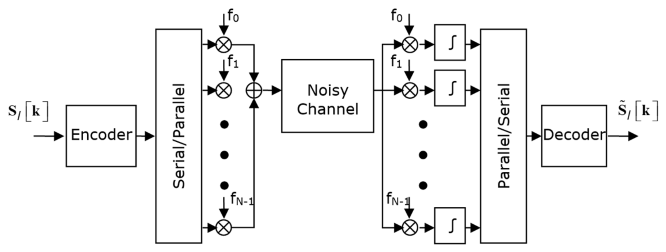
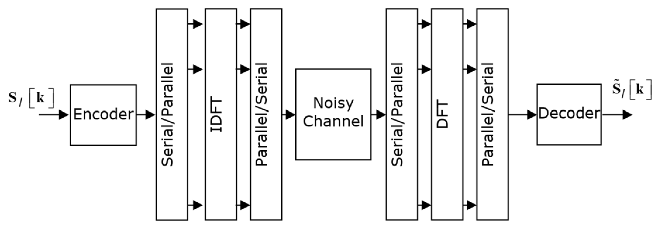
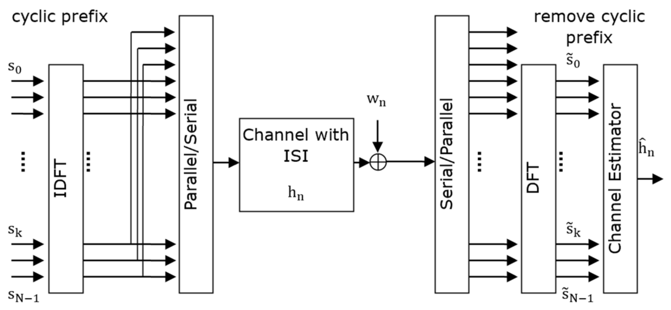
Figure 1 illustrates the OFDM transmitter used in the training stage, while Figure 2 and Figure 3 show its MATLAB implementation based on the IDFT/DFT and IFFT/FFT blocks, respectively. In this stage, all OFDM subcarriers carry known pilot symbols, which allows for reliable estimation of the channel frequency response.
It is assumed that the training sequence s N is BPSK modulated and transmitted over the channel using the OFDM transmission technique. The block diagram for OFDM transmission is shown in Figure 1. The transmission system operation shown in Figure 1, which uses the Discrete Fourier Transform (DFT) and the Inverse Discrete Fourier Transform (IDFT), was implemented in MATLAB. This implementation is shown in Figure 2.
To estimate h , the block diagram in Figure 3 is used. Since the learning sequence is known at reception, it does not need to be encoded or decoded. Thus, the encoding and decoding blocks can be omitted.
The training symbols s N are modulated onto N subcarriers using the Inverse Discrete Fourier Transform, and the last L values are copied and put as a preamble (cyclic prefix) to form the OFDM symbol. The cyclic prefix separates two successive OFDM blocks and facilitates channel equalization at the receiver. It also allows demodulator synchronization, eliminates interference between two successive OFDM symbols, as well as inter-channel interference.
This data vector is transmitted serially over a discrete channel in time, with the length of the channel’s impulse response being less than L . At the receiver, the cyclic prefix is removed. The signal is demodulated using the Discrete Fourier Transform [41].
It was considered a single-antenna OFDM system with N subcarriers per OFDM symbol. Within one frame, a binary information sequence b ∈ 0,1 k is processed as follows.
First, the information bits bare encoded using a binary channel code (e.g., convolutional or turbo code) to produce coded bits b c , which are then interleaved. The interleaved coded bits are mapped to complex modulation symbols as in:
d = d 0 , d 1 , … , d N d − 1 T ,
drawn from a constellation δ (e.g., BPSK or 16-QAM), with average symbol energy as in:
d i 2 = E s .
A known BPSK training sequence, as in:
s N = s 0 , … , s N − 1 T ,
where length N is inserted for channel estimation. Depending on the scenario, N ∈ { 8,18,64 } , and pilots are mapped onto all subcarriers of one or more OFDM symbols.
For each OFDM symbol, the frequency-domain vector x (either pilots or data) is converted to the time domain via the inverse discrete Fourier transform (IDFT), such as:
x t = F H x ,
where F is the unitary N × N DFT matrix. A cyclic prefix (CP) of length L ≥ L h − 1 is prepended, resulting in the transmit vector x c p .
The baseband channel is modeled as a finite impulse response (FIR) filter with the impulse response as in:
h = h 0 , … , h L h − 1 T ,
assumed to be quasi-static over one frame. The received CP-extended time-domain signal is given by:
r = H c x c p + n ,
where H c is the convolution matrix corresponding to h , and n is complex additive white Gaussian noise (AWGN) with variance σ n 2 per dimension [42].
At the receiver, the CP is first removed, yielding r N ∈ C N , and a DFT is applied as in:
y = F r n = F H c F H x + F n .
Since H c is circulant due to the CP, F H c F H is diagonal, resulting in:
y = H f x + N ,
where
H f = d i a g H 0 , … , H N − 1 ,
and N has the same variance as n . Equation (9) contains the channel frequency response for each OFDM subcarrier. Since all transmitted pilot symbols are known at the receiver, either the Least Squares (LS) algorithm or the Minimum Mean Square Error (MMSE) algorithm can be applied to estimate the channel response. The initial channel estimate is denoted by h ^ 0 .
The signal-to-noise ratio (SNR) per symbol is defined as:
S N R = E s σ n 2
where σ n 2 = E s 2 R c 10 E b / N 0 ( d B ) / 10 , in which E s represents the energy of the transmitted BPSK symbol; R c is the turbo code rate and E b is the energy per information bit.
It should be emphasized that the OFDM training phase ends immediately after this initial channel estimate has been obtained. The subsequent BER performance evaluation does not involve the transmission of any additional OFDM symbols. Instead, a new independent sequence of turbo-coded BPSK data is generated and transmitted through the same propagation channel. The receiver equalizer is initialized using the previously obtained channel estimate, h ^ 0 . Two receiver architectures are subsequently investigated.
In the first architecture, the initial channel estimate obtained using either the LS or MMSE algorithm remains unchanged throughout the entire iterative turbo detection process. In the second architecture, the initial estimate serves only as the starting point for an iterative decision-directed channel estimation procedure, in which the reconstructed symbols generated by the SISO equalizer and the decoder are used to progressively refine the channel estimate after each iteration.
In summary, the complete simulation framework consists of two distinct but interconnected stages. The first stage provides the initial channel state information through an OFDM training transmission, while the second stage evaluates how different channel estimation strategies affect the performance of the iterative turbo receiver. This organization closely reflects the MATLAB implementation used throughout this work and establishes a complete and coherent end-to-end processing framework that forms the basis for the receiver architectures presented in the following sections.

4. Turbo Equalizer Architectures: Fixed vs. Iterative Channel Estimation

A detailed description is now provided of the two turbo equalizer architectures illustrated next, along with their adaptation to OFDM.
Figure 4 and Figure 5 exclusively illustrate the proposed iterative receiver, which operates after the OFDM demodulation stage. The conventional blocks of the OFDM system (FFT/IFFT, cyclic prefix management, and initial channel estimation) are not represented in these figures for simplicity, as they have already been described in the general system model presented previously, in Section 3.
After the OFDM training step described in the previous section, the receiver operates using the initial channel estimate obtained from the known training sequence ( h ^ 0 ). The subsequent processing is identical for both analyzed architectures up to the channel estimation block. The difference between the two approaches lies exclusively in how the channel estimate is used and updated during the iterative equalization and decoding process.
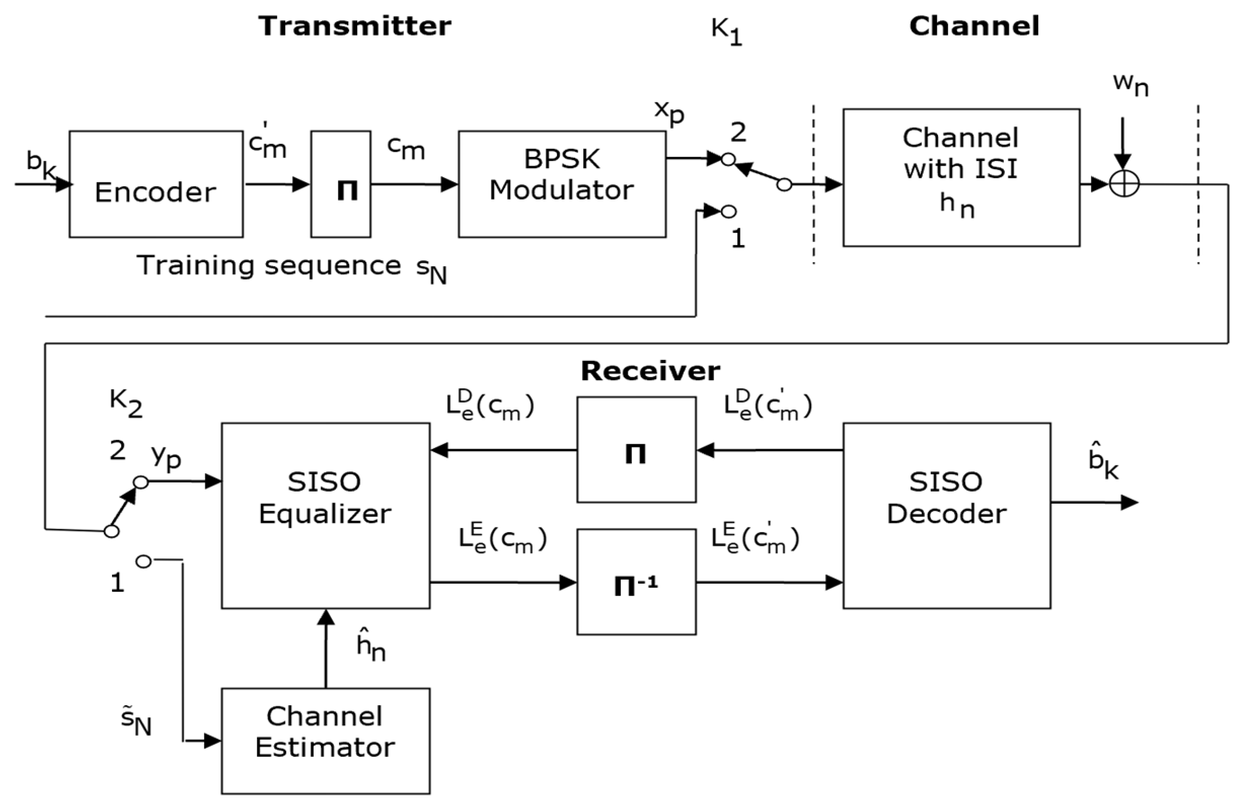
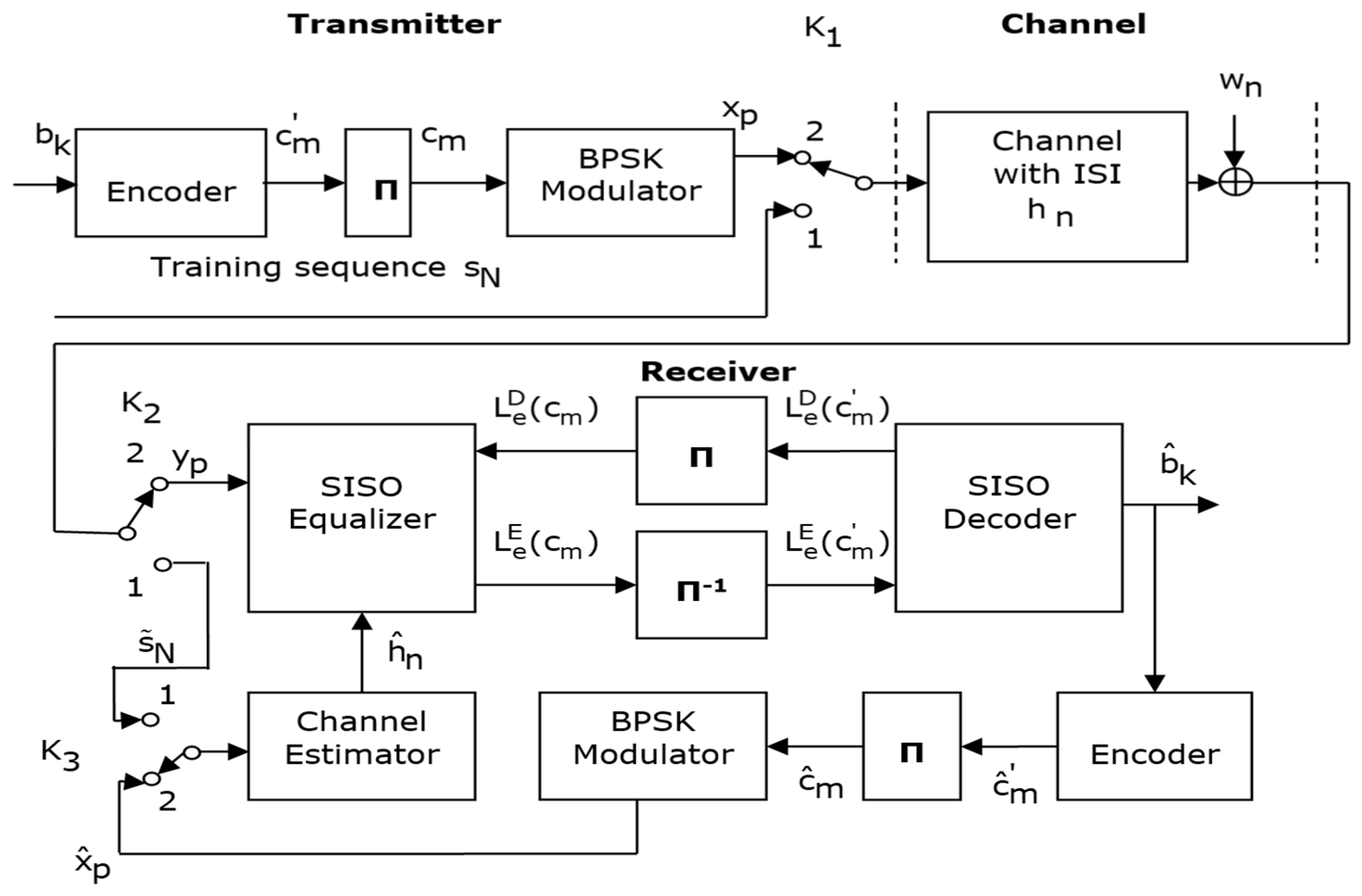
To investigate the influence of the channel estimation method on the overall receiver performance, two turbo architectures are analyzed. The first architecture (Figure 4) uses a conventional channel estimate, obtained from the training sequence and kept constant throughout the iterative process. The second architecture introduces iterative channel estimation based on decision-guided methods inside the turbo loop (Figure 5). Both architectures use the same SISO equalizer, the same turbo decoder and the same iterative mechanism for exchanging extrinsic information, so that the comparison highlights exclusively the influence of the channel estimation strategy.

4.1. Non-Iterative Training-Aided Turbo Equalizer (Figure 4-Type Architecture)

In the architecture illustrated in Figure 4, turbo equalization is used for detection and decoding, but channel estimation is performed only once from the training sequence.
In Figure 4 the transmitted bits b k are encoded using a recursive systematic convolutional (RSC) encoder with rate R = 1 2 and constraint length K = 3 , and defined through specific generator polynomials expressed in octal form G 0 = 7 and G 1 = 5 .
The resulting coded bit sequence c m ′ undergoes block interleaving, producing a permuted sequence c m , which is subsequently modulated using Binary Phase Shift Keying (BPSK) to obtain the transmitted signal sequence x p .
At the receiver, the observed signal y p is affected by intersymbol interference (ISI), which must be mitigated to ensure reliable detection. The notation b ^ k denotes the estimated (recovered) bits at the receiver.
As depicted in Figure 4, when switches K1 and K2 are set to position 1, a training sequence s N is generated. This sequence is known a priori to the channel estimator at the receiver. After transmission through the channel, it becomes distorted by channel effects and additive noise.
By comparing the received sequence s ~ N with the known transmitted sequence s N , an estimate of the channel impulse response, denoted h ^ n , can be obtained using appropriate channel estimation techniques. Once this estimate is available, further signal processing can be performed at the receiver. The iterative receiver is designed such that equalization and decoding are jointly executed in an integrated iterative framework.
The receiver architecture consists of two primary functional blocks: an equalization unit and a decoding unit.
The equalization stage itself includes two main components: a channel estimator and a soft-input soft-output (SISO) equalizer. In addition to the received signal, the SISO equalizer requires knowledge of the estimated channel impulse response h ^ n , which is provided by the channel estimator.
In the following sections, the mathematical expressions associated with the soft information employed in the turbo equalization framework will be introduced and discussed.
The SISO equalizer receives as input both the observation vector y p , corresponding to the channel output affected by Gaussian noise w n , and the a priori probabilistic information supplied by the SISO decoder, denoted L e D c m . At the initial iteration, this a priori term is set to zero, indicating that no prior information is yet available from the decoder. The equalizer then generates extrinsic information L e E c m , which is subsequently deinterleaved to form a reordered sequence L e E c m ′ . This sequence is used as a priori input for the SISO decoder.
In turn, the decoder produces its own extrinsic information L e D c m ′ , which is interleaved to obtain the sequence L e D c m . This updated information is fed back to the SISO equalizer, where it serves as refined a priori input for the next equalization step, alongside the received signal y p .
This iterative exchange between equalization and decoding continues until a predefined stopping condition is met [43]. Ultimately, the decoder output b ^ k represents the estimated version of the transmitted bit sequence.
The receiver operates through repeated exchanges of information between the equalizer and the decoder, with interleaving and deinterleaving processes acting as intermediate steps, as outlined below [43,44,45,46]:
  • SISO Equalizer: Its role is to mitigate or suppress the intersymbol interference (ISI) introduced by the multipath propagation channel.
  • Interleaving/Deinterleaving Block: This block is responsible for dispersing bursts of errors that may appear at the equalizer output, thereby reducing the risk of error propagation. Additionally, it helps decorrelate the probabilistic information exchanged between the equalizer and the decoder. As a result, the performance of the iterative receiver improves significantly, especially when the interleaver is properly designed and sufficiently large.
  • SISO Decoder: This component enables the iterative decoding process at the receiver by exchanging probabilistic (soft) information with the equalizer over multiple iterations, thereby progressively improving the reliability of the estimated data.
A variety of equalization techniques can be employed to mitigate the effects of intersymbol interference (ISI). Among these, algorithms based on trellis-based searches—such as Maximum Likelihood (ML) and Maximum A Posteriori (MAP)—are widely used due to their ability to achieve strong performance while maintaining a reasonable level of computational complexity [46]. Optimal equalization methods that exploit the trellis representation of the channel, including the Bahl–Cocke–Jelinek–Raviv (BCJR) algorithm and the Soft Output Viterbi Algorithm (SOVA), are known to deliver highly accurate results [47,48]. However, their effectiveness depends on having precise knowledge of the channel or a highly accurate estimate of it. In this work, the BCJR algorithm is employed. This algorithm performs decoding by operating on a trellis structure and computes probabilities for each transmitted bit or symbol using a recursive implementation of the MAP criterion. Unlike the Viterbi algorithm, which determines the most likely transmitted sequence based on a global ML decision, the BCJR algorithm evaluates the posterior probabilities of individual symbols.
Within the framework illustrated in Figure 4, the estimation of the channel impulse response h ^ n is carried out a single time.
  • Training mode, with switches K1 and K2 set to position 1:
    • A known BPSK training sequence, denoted by s N , is transmitted over the channel and received as s ~ N ;
    • The channel estimator computes the initial channel estimate h ^ 0 using either the LS or MMSE estimator, based on the time-domain formulation or, equivalently, the OFDM frequency-domain representation.
  • Data mode, with switches in position 2:
    • Data bits are encoded, interleaved, and modulated into OFDM symbols;
    • The received OFDM signal is equalized using the initial channel estimate h ^ 0 to mitigate channel distortion;
    • A SISO equalizer and a SISO decoder form a turbo loop (extrinsic LLR exchange), but the channel estimate remains fixed across iterations.
This structure corresponds to many practical OFDM receivers where pilot-based channel estimation is performed once per frame, and then iterative detection/decoding is performed on top of a fixed channel estimate.

4.2. Iterative Turbo Equalizer with Decision-Directed Channel Estimation (Figure 5-Type Architecture)

The second architecture illustrated in Figure 5 embeds channel estimation into the turbo loop itself.
In Figure 5, the estimated bits b ^ k obtained at each iteration are processed again through the transmitter chain: they are first re-encoded, resulting in c ^ m ′ , then interleaved to form c ^ m , and finally modulated in the same manner as at the transmitter. The sequence generated in this way is applied to the channel estimation block, which uses the received signal y p to compute an updated estimate of the channel impulse response h ^ n . This refined estimate is subsequently passed to the SISO equalizer.
During the transmission of the training sequence, the switches are positioned in state 1, whereas during the actual data transmission phase, they are switched to position 2. In this configuration, the channel estimator can rely on the same estimation technique both for the initial estimation phase—when the known training sequence s N is available—and for the later updates, when the reconstructed sequence x ^ p is used. Alternatively, different estimation approaches may be employed for these stages, such as the Least Squares (LS) method or the Minimum Mean Square Error (MMSE) criterion.
  • Initial training (iteration 0):
    • Identical to Figure 4, a training sequence is used to obtain the initial channel estimate h ^ 0 using either the LS or MMSE estimator.
  • Turbo iterations ( i = 1,2 , … ):
    • Using the channel estimate h ^ i − 1 , the SISO equalizer computes soft symbol estimates and log-likelihood ratios (LLRs) for the coded bits;
    • The SISO decoder refines the bit probability estimates b ^ i ;
    • The refined bit estimates are re-encoded, interleaved, and modulated to generate the reconstructed symbol sequence x ^ p ( i ) ;
    • Using x ^ p ( i ) and the corresponding received signal, the channel estimator computes an updated channel estimate h ^ i via the LS estimator, with optional MMSE refinement;
    • The updated channel estimate h ^ i is then fed back to the SISO equalizer for the subsequent turbo iteration.
We consider the following:
  • LS–LS iterative scheme: The initial channel estimate h ^ 0 is obtained via LS, and all subsequent updates h ^ i , for i ≥ 1 , are also computed using LS;
  • MMSE–LS iterative scheme: The initial channel estimate h ^ 0 is obtained via MMSE, while all subsequent updates h ^ i , for i ≥ 1 , are computed using LS.
This decision-directed turbo equalization architecture effectively transforms the initial short training sequence into a longer “virtual” training by exploiting decoder decisions across iterations.
All details concerning the SISO equalizer algorithm and the decoder implementation can be found in [49].

5. LS and MMSE Channel Estimation in the Turbo Equalizer

The LS and MMSE estimators are recalled in forms that naturally integrate with the turbo equalization architectures previously presented in Figure 4 and Figure 5.

5.1. Time-Domain LS Estimation (Training Phase)

Consider a known training sequence s N of length N transmitted over a channel with impulse response h . The received signal is modeled as in:
s ~ N = S h + n ,
where S ∈ R N × L h (or C N × L h ) is a Toeplitz matrix constructed from s N , and n denotes additive noise.
The least squares (LS) estimate of the channel impulse response is given by:
h ^ L S = S H S − 1 S H s ~ N .
This estimator is employed in the training branch of the turbo equalizer depicted in Figure 4. When switches K1 and K2 are set to position 1, the known training sequence s N is applied to the LS estimator to obtain the channel estimate h ^ , which is subsequently used by the soft-input soft-output (SISO) equalizer.

5.2. Decision-Directed LS Estimation (Iterative Phase)

In the iterative turbo equalizer shown in Figure 5, after each turbo iteration i , the decoder decisions b ^ i are re-encoded, interleaved, and remodulated in order to reconstruct a symbol sequence x ^ p ( i ) , which is time-aligned with the corresponding received signal y . Based on this reconstructed sequence, the Least Squares (LS) channel estimate is updated as in:
h ^ L S ( i ) = X ^ ( i ) T X ^ ( i ) − 1 X ^ ( i ) T y ,
where X ^ ( i ) denotes the Toeplitz matrix constructed from the reconstructed symbol sequence x ^ p ( i ) .
This formulation reflects the operating principle illustrated in Figure 5: the channel estimator is driven by reconstructed (decision-directed) sequences, rather than by a purely known training sequence, and the channel estimate h ^ i is refined at each turbo iteration.

5.3. LS and MMSE in the OFDM Domain

During OFDM training symbol transmission, where pilot symbols are transmitted on all subcarriers, the received signal in the frequency domain can be written as:
y = X h f + n ,
where X = d i a g s 0 ,   s 1 , … , s N − 1 , is a diagonal matrix containing the known pilot symbols on each subcarrier, h f is the frequency-domain channel vector, and n denotes additive noise.
For each subcarrier k , the least-squares (LS) estimate of the channel frequency response is given by:
H ^ k , L S = y k s k .
By stacking the per-subcarrier LS estimates into a vector, the overall LS channel estimate in the frequency domain can be expressed compactly as:
h ^ f , L S = X − 1 y .
The time-domain least-squares (LS) channel estimate, denoted by h ^ L S , is obtained by applying an inverse discrete Fourier transform (IDFT) to the frequency-domain LS estimate and subsequently truncating the channel impulse response to its assumed length. When the full pilot OFDM symbol is exploited, this OFDM-based LS estimator is equivalent to the classical time-domain LS formulation.
For the minimum mean-square error (MMSE) estimator, let R h h = E h h H denote the channel covariance matrix in the time domain. The linear MMSE (MMSE) channel estimate is given by:
h ^ M M S E = W h ^ L S ,
where the MMSE weighting matrix W is defined as:
W = R h h R h h + σ n 2 S H S − 1 − 1 .
Equivalently, the MMSE channel estimate may be computed directly in the frequency domain by using the frequency-domain channel covariance matrix. In this paper, the MMSE channel estimate is used as the initial channel estimate in the MMSE-based turbo equalization scheme. Specifically, the MMSE estimate is employed at iteration i = 0 , while LS-based channel estimates are used in the subsequent iterations.

6. Simulation Results

All simulations were performed in MATLAB. The information bits were generated randomly, and a random interleaver was employed. The turbo decoder was configured to perform five decoding iterations, as reflected in the BER curves presented in Figure 6, Figure 7, Figure 8 and Figure 9. For each simulation scenario, the number of generated sequences was 10,000. The decoder was set to perform 5 iterations, because after these, no further improvements are made to the estimation.
The following configurations were compared:
  • Non-iterative turbo equalizer with LS (“LS” type);
  • Iterative turbo equalizer with LS–LS (“LS–LS” type);
  • Non-iterative turbo equalizer with MMSE (“MMSE” type);
  • Iterative turbo equalizer with MMSE–LS (“MMSE–LS” type).

6.1. Bit Error Rate (BER) as a Function of Signal-to-Noise Ratio Using the LS Estimation Algorithm

The length of the transmitted data sequence was kept at 128 ( k = 128 ); only the length of the learning sequence was changed ( N = 8 ,   18 ,   64 ). Also, the cyclic prefix was fixed at 8 ( L = 8 ).
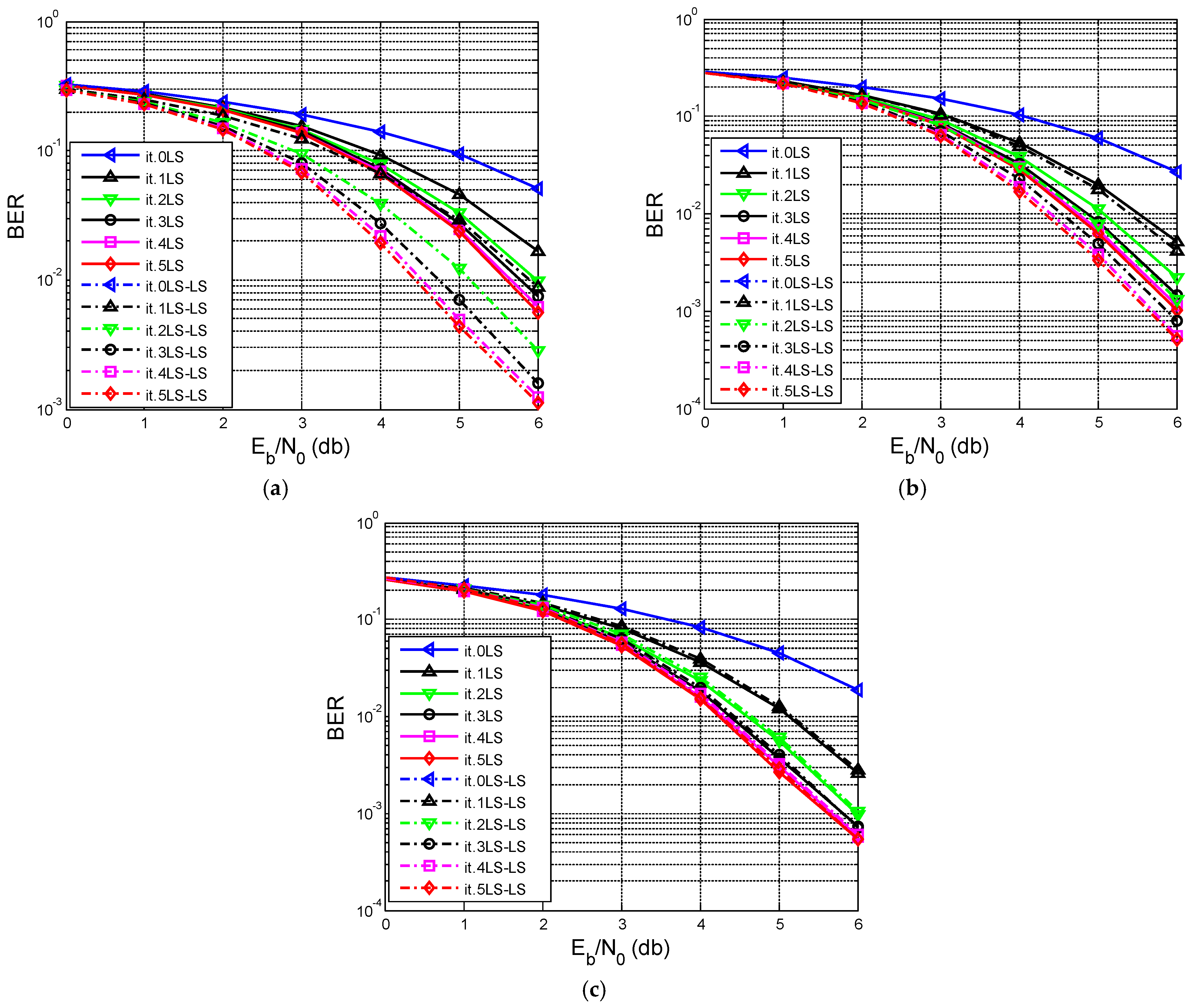
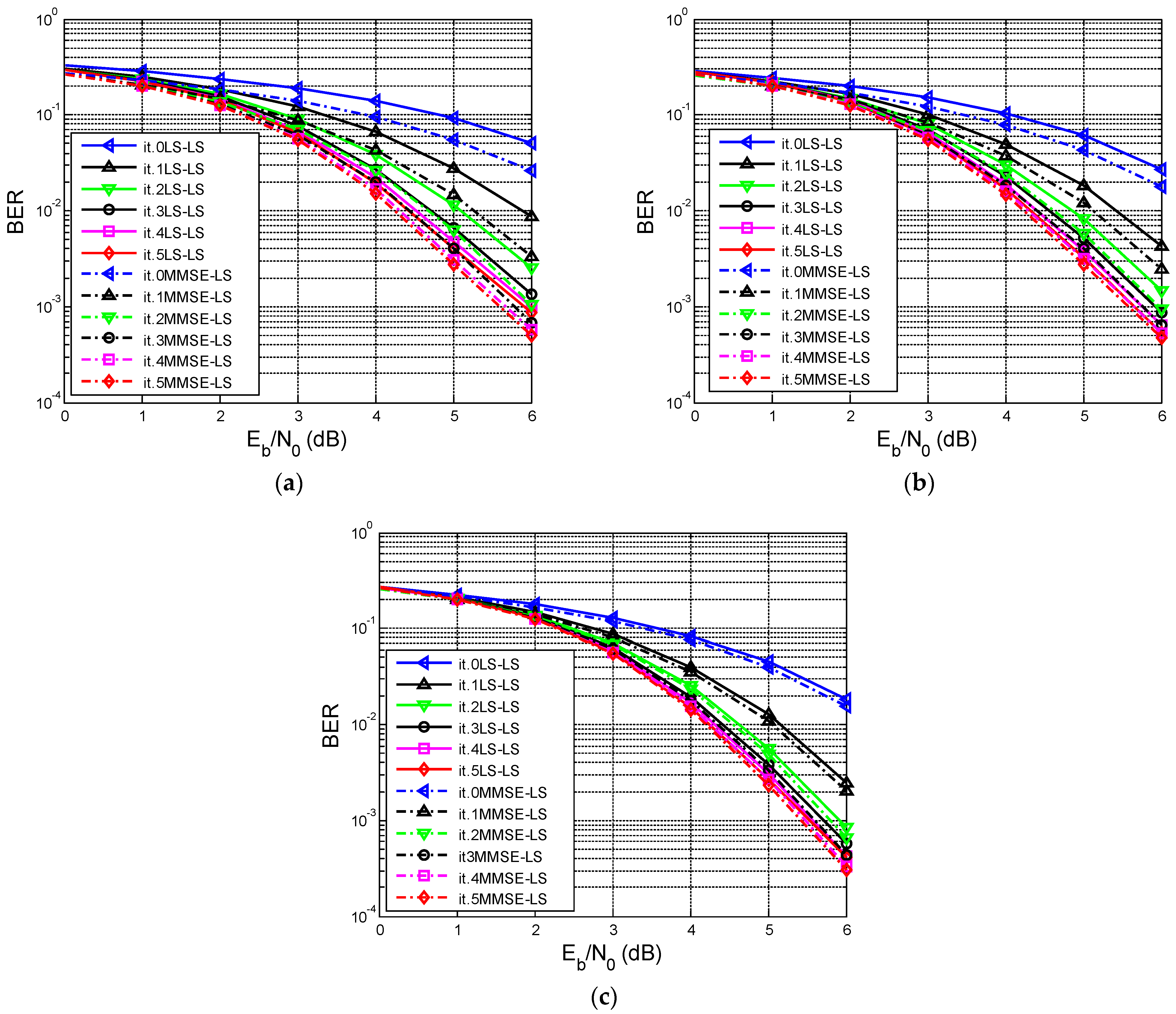
In Figure 6a–c, the notation “LS” represents the results obtained with the scheme in Figure 4 using the LS algorithm, and “LS-LS” represents the results obtained with the scheme in Figure 5 using the LS algorithm both in the initial estimate and in the estimates corresponding to each iteration. From the analysis of the graphs presented in Figure 6a–c, it is now clear that the estimation becomes more precise with the increase in the length of the learning sequence. The scheme in Figure 4 can be used for a long learning sequence, while the scheme in Figure 5 is suitable for a short sequence.
Several conclusions can be highlighted as follows:
  • Increasing N improves channel estimation for both architectures, reducing BER.
  • Short lengths of learning sequences ( N = 8 ,   18 ): the LS estimate from a short training block is inaccurate. In the Figure 4-type receiver, this causes performance degradation and potential BER floors. In the Figure 5-type receiver, iterative LS updates based on decoder decisions significantly improve performance, particularly at medium-to-high SNR.
  • Long lengths of learning sequences ( N = 64 ): the LS estimate from training is already accurate; the difference between the LS and LS–LS curves becomes negligible.

6.2. Bit Error Rate (BER) as a Function of Signal-to-Noise Ratio Using the MMSE Estimation Algorithm

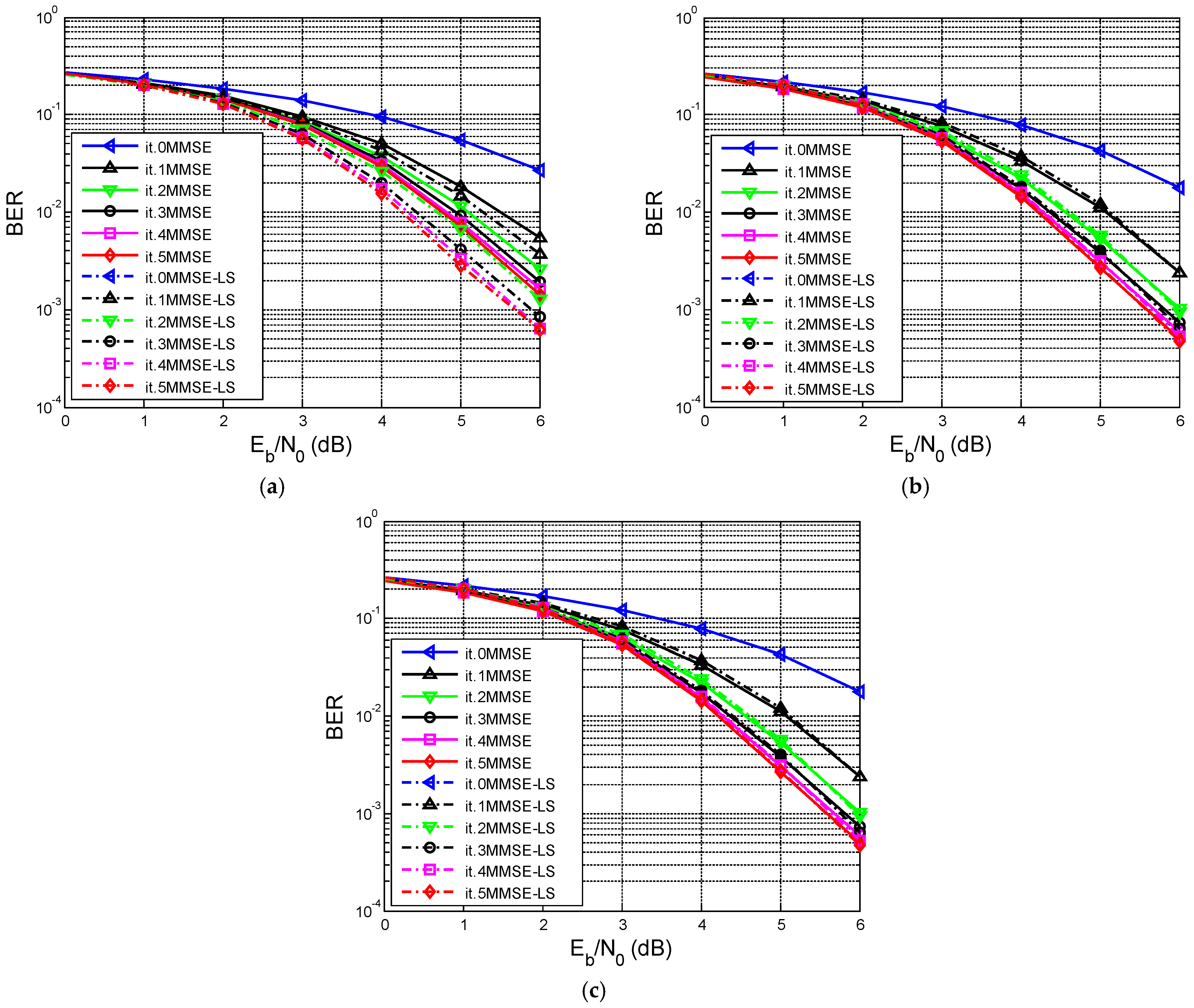
On the graphs in Figure 7a–c the notation “MMSE” represents the results obtained with the scheme in Figure 4 using the MMSE algorithm, and “MMSE-LS” represents the results obtained with the scheme in Figure 5 using the MMSE algorithm for the initial estimation (iteration 0), and the LS algorithm for the estimations in the following iterations. As can be observed, using the MMSE algorithm in the scheme in Figure 4, better results are obtained than with the LS algorithm for shorter length training sequences. However, for short-length learning sequences (when the estimate of h is less good), the scheme presented in Figure 5 is recommended.
It was found that:
  • For short lengths of learning sequences, MMSE outperforms LS in the non-iterative case, as expected;
  • The MMSE–LS iterative scheme further improves BER, combining good initialization with decision-directed refinement;
  • For long learning sequences, the gap between MMSE and MMSE–LS is small, reflecting the accuracy of the initial MMSE estimate.

6.3. Comparison of Results Using the LS and MMSE Algorithms with the Scheme in Figure 4

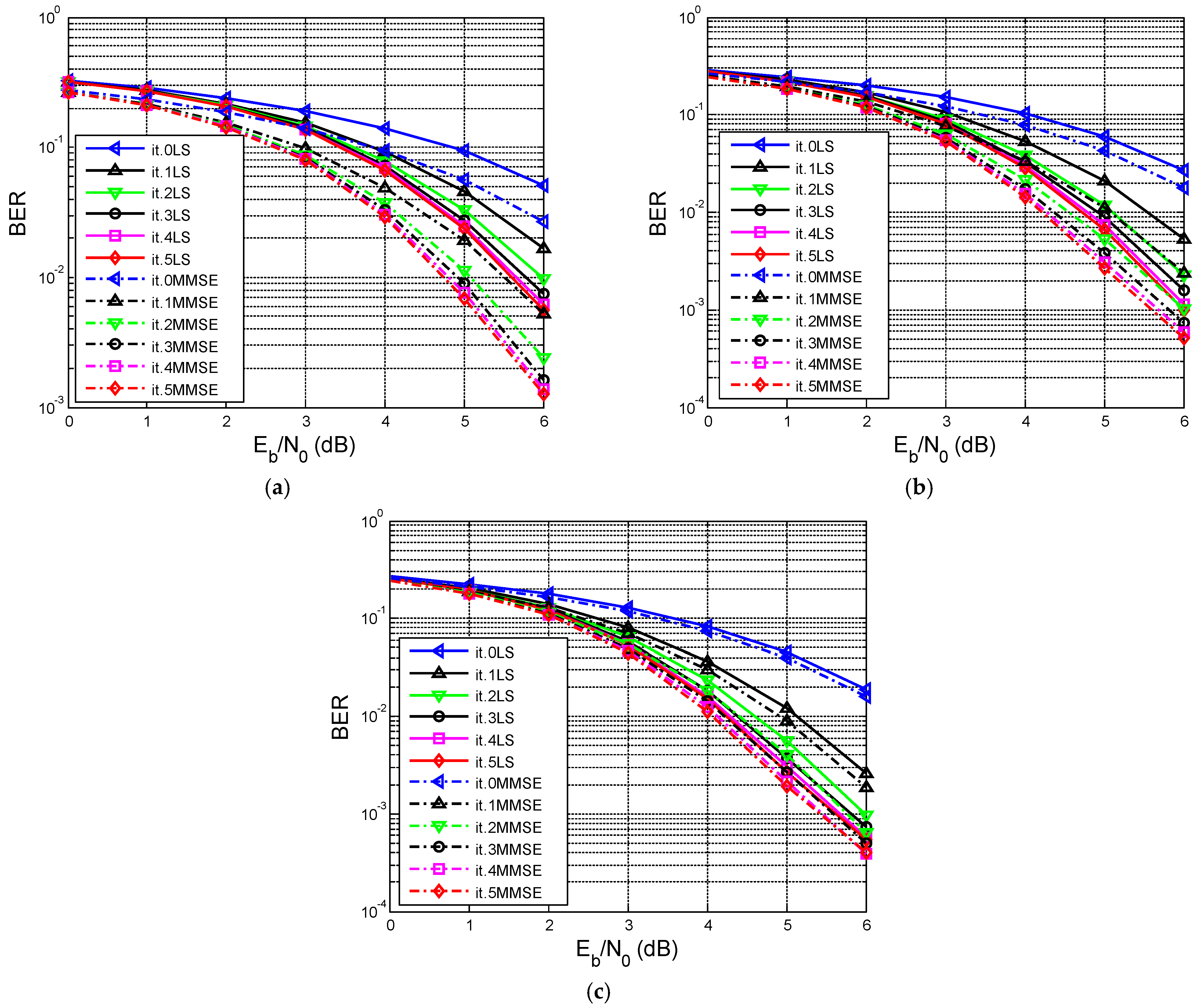
From the results presented in Figure 8a–c, it can be observed that for short training sequences, the bit error rate is lower in the case of MMSE estimation than in the case of LS estimation. For long training sequences, the estimation performances of the two algorithms are close. In summary, for N = 8 and N = 18 , MMSE clearly outperforms LS at target BERs of interest. For N = 64 , LS and MMSE curves are close, as the longer training mitigates LS suboptimality.

6.4. Comparison Between the Results Obtained with the Scheme in Figure 5 Using the LS and MMSE Algorithms

Following the results obtained using the scheme in Figure 5, presented in Figure 9a–c, it can be seen that as the length of the training sequence increases, the performances of the two algorithms become similar. For short training sequences, better performance is obtained using the MMSE algorithm than the LS algorithm.
All the simulation scenarios considered are summarized in Table 1 to make them easier for the reader to follow.
In summary, for short training sequences, MMSE initialization (MMSE–LS) yields lower BER than pure LS–LS, underscoring the advantage of high-quality initial channel estimates in turbo equalization. However, for long training sequences, LS–LS and MMSE–LS nearly coincide. The simulation results highlight the strong dependence of turbo equalization performance on both the channel estimation algorithm and the length of the training sequence.

6.5. Quantitative Comparison with Related Literature

To assess the practical relevance of the proposed methodology, the obtained results were analyzed and compared with representative works from the specialized literature investigating iterative channel estimation in OFDM and MIMO-OFDM systems [39,40].
In the work of Ylioinas and Juntti [39], iterative channel estimation in a turbo-coded MIMO-OFDM system leads to gains of about 1–2 dB compared to conventional estimation based solely on pilot symbols. Similarly, Oyerinde and Mneney [40] report that the use of soft information provided by the decoder significantly reduces the BER, especially under conditions of short training sequences.
The results obtained in this work highlight the same trend. For the short training sequence (N = 8), the iterative architecture (Figure 5) reduces the BER from about 1.5 × 10⁻² for the conventional LS estimator to about 1.2 × 10⁻³ for the iterative LS-LS scheme (Table 1). This corresponds to a BER reduction of about 92%, or a gain of close to an order of magnitude.
In the case of MMSE estimation, the iterative MMSE-LS scheme reduces the BER from about 1.9 × 10⁻² to 1.5 × 10⁻³, which represents an improvement of about 92.1%. These values are comparable to the improvements reported in the literature for turbo receivers with iterative channel estimation.
As the training sequence length increases (N = 18 and N = 64), the difference between the conventional and iterative estimation becomes much smaller. This behavior is in agreement with the results reported in [39,40], where it is shown that the benefit of iterative estimation is maximum when the initial information about the channel is limited or imprecise.
However, it should be emphasized that the absolute performances cannot be directly compared with those reported in [39,40], because the analyzed configurations are different. The respective works consider MIMO-OFDM systems and more complex propagation scenarios, while the present study uses a single-antenna OFDM system, BPSK modulation and an AWGN channel with ISI. For this reason, the comparison should be interpreted as one of qualitative order and of performance trends, not as a direct comparison of BER values.
The analysis highlights that the main contribution of the proposed method does not lie in the development of a new LS or MMSE estimator, but in the integration of channel estimation into the iterative turbo equalization loop and in the identification of the conditions under which this strategy is justified from the point of view of the performance–complexity trade-off. The results show that the use of iterative estimation is recommended especially for short training sequences (N ≤ 18), while for N = 64 the additional advantage is marginal and does not always justify the additional complexity.
Although more advanced channel estimation methods based on compressed detection or deep learning can provide additional performance gains, they generally require either sparsity assumptions, offline training datasets, or significantly higher computational complexity. In contrast, the proposed approach relies exclusively on classical LS/MMSE estimation integrated in the turbo loop, which makes it easier to implement in practical OFDM receivers.

7. Conclusions

This paper has presented and evaluated two iterative turbo receiver architectures (illustrated in Figure 4 and Figure 5) that combine OFDM-based channel estimation with decision-directed channel refinement for turbo-coded BPSK transmission over frequency-selective channels. The proposed simulation framework explicitly separates the OFDM training stage, which is used exclusively to obtain the initial channel estimate, from the subsequent BER evaluation stage, during which the iterative receiver operates using independently generated turbo-coded data.
The results demonstrate that:
  • When the training sequence is short, iterative processing and MMSE-based initialization provide substantial performance gains;
  • When the training sequence is long, the choice between LS and MMSE becomes less critical, and iterative refinement yields limited additional benefit;
  • The iterative turbo equalizer is particularly advantageous in training-limited scenarios, where decision-directed channel updates can effectively compensate for initial estimation inaccuracies.
The data sequence that is now transmitted on a carrier using Turbo coding will also be transmitted on another nearby carrier using other types of LDPC coding and Polar codes. At reception, a re-estimation technique is used to monitor the performance of the codes under different SNR conditions.
These insights are directly relevant for OFDM deployments in 3GPP-type systems, where turbo equalization and iterative channel estimation can be selectively applied to balance performance and complexity. Future work could extend this turbo equalization framework to MIMO-OFDM systems, while also accounting for practical hardware impairments, and could explore hybrid approaches that combine iterative channel estimation with basis expansion or compressed sensing for next-generation wireless systems.
Another future perspective could be to take an image or sound and break it down into bits and then transmit and receive it using the respective models. Then, using image or sound correction algorithms, we would try to recover as much of the original as possible. We plan to do something like this in the future; for now, we have just limited ourselves to transmitting bits, because everything ultimately comes down to bits.

Author Contributions

Conceptualization, F.L.M. and A.-M.C.; methodology, F.L.M. and A.-M.C.; software, F.L.M. and A.-M.C.; validation, F.L.M. and A.-M.C.; formal analysis, A.-M.C.; investigation, F.L.M.; resources, F.L.M.; data curation, F.L.M.; writing—original draft preparation, F.L.M. and A.-M.C.; writing—review and editing, F.L.M. and A.-M.C.; visualization, F.L.M.; supervision, F.L.M. and A.-M.C. All authors have read and agreed to the published version of the manuscript.

Funding

The article publication fee will be funded by the University of Oradea.

Institutional Review Board Statement

Not applicable.

Informed Consent Statement

Not applicable.

Data Availability Statement

The data presented in this article are available on request from the corresponding author.

Conflicts of Interest

The authors declare no conflicts of interest.

References

  1. Huang, Y.; Hu, S.; Ma, S.; Liu, Z.; Xiao, M. Designing Low-PAPR Waveform for OFDM-Based RadCom Systems. IEEE Trans. Wirel. Commun. 2022, 21, 6979–6993. [Google Scholar] [CrossRef] [Scilit]
  2. Parvini, M.; Qurratulain Khan, M.; Schulz, P.; Fettweis, G. An Optimized OFDM Waveform Design for 6G Industrial Networks. IEEE Trans. Wirel. Commun. 2024, 23, 17324–17338. [Google Scholar] [CrossRef] [Scilit]
  3. De Beelde, B.; Vantorre, M.; Castellanos, G.; Pickavet, M.; Joseph, W. MmWave Physical Layer Network Modeling and Planning for Fixed Wireless Access Applications. Sensors 2023, 23, 2280. [Google Scholar] [CrossRef] [Scilit]
  4. Lodhi, K.; Chhillar, J.; Darak, S.J.; Sharma, D. Design and Performance Analysis of Hardware Realization of 3GPP Physical Layer for 5G Cell Search. Chips 2023, 2, 223–242. [Google Scholar] [CrossRef] [Scilit]
  5. Hong, H.; Wong, K.-K.; Xu, H.; Xu, Y.; Shin, H.; Murch, R.; He, D.; Zhang, W. Downlink OFDM-FAMA in 5G-NR Systems. IEEE Trans. Wirel. Commun. 2025, 24, 10116–10132. [Google Scholar] [CrossRef] [Scilit]
  6. Niu, J.; He, X.; Fang, B.; Han, G.; Wang, X.; He, J. CSI-F: A Human Motion Recognition Method Based on Channel-State-Information Signal Feature Fusion. Sensors 2024, 24, 862. [Google Scholar] [CrossRef] [Scilit]
  7. Almeida, I.; Guerreiro, J.; Dinis, R. On Deep Learning Hybrid Architectures for MIMO-OFDM Channel Estimation. Electronics 2025, 14, 4692. [Google Scholar] [CrossRef] [Scilit]
  8. Qadri, S.S.U.; Arif, M.; Naseem, I.; Moinuddin, M. Robust Incremental Least Mean Square Algorithm with Dynamic Combiner. IEEE Access 2022, 10, 75135–75143. [Google Scholar] [CrossRef] [Scilit]
  9. Wu, C.; You, C.; Liu, Y.; Gu, X.; Cai, Y. Channel Estimation for STAR-RIS-Aided Wireless Communication. IEEE Commun. Lett. 2022, 26, 652–656. [Google Scholar] [CrossRef] [Scilit]
  10. Brosch, A.; Hanke, S.; Wallscheid, O.; Böcker, J. Data-Driven Recursive Least Squares Estimation for Model Predictive Current Control of Permanent Magnet Synchronous Motors. IEEE Trans. Power Electron. 2021, 36, 2179–2190. [Google Scholar] [CrossRef] [Scilit]
  11. Gashtasbi, A.; Marques da Silva, M.; Dinis, R. Improved Low-Complexity, Pilot-Based Channel Estimation for Large Intelligent Surface Systems. Appl. Sci. 2025, 15, 3743. [Google Scholar] [CrossRef] [Scilit]
  12. Kwon, N.; Yoon, B.; Kim, J. Multiscale Convolution-Based Efficient Channel Estimation Techniques for OFDM Systems. Electronics 2025, 14, 307. [Google Scholar] [CrossRef] [Scilit]
  13. Yang, S.; Li, Y.; Liu, L.; Xia, J.; Wang, B.; Li, X. Channel Estimation for Massive MIMO Systems via Polarized Self-Attention-Aided Channel Estimation Neural Network. Entropy 2025, 27, 220. [Google Scholar] [CrossRef] [Scilit]
  14. Zhou, X.; Zhang, J.; Wen, C.-K.; Jin, S.; Han, S. Graph Neural Network-Enhanced Expectation Propagation Algorithm for MIMO Turbo Receivers. IEEE Trans. Signal Process. 2023, 71, 3458–3473. [Google Scholar] [CrossRef] [Scilit]
  15. Pan, Z.; Hou, F.; Jiang, X.; Liu, F.; Wang, S.; Lu, H.; Han, Y.; Chen, J.; Ning, Y. Co-Design of Pipelining and Fixed-Point Quantization for SOVA-Turbo Codec IP Core. Electronics 2026, 15, 1954. [Google Scholar] [CrossRef] [Scilit]
  16. Wang, J.; Jiang, C.; Kuang, L. High-Mobility Satellite-UAV Communications: Challenges, Solutions, and Future Research Trends. IEEE Commun. Mag. 2022, 60, 38–43. [Google Scholar] [CrossRef] [Scilit]
  17. Luo, Q.; Zhu, J.; Liu, Z.; Tang, Y.; Xiao, P.; Chen, G.; Shi, J. Joint Sparse Graph for Enhanced MIMO-AFDM Receiver Design. IEEE Trans. Wirel. Commun. 2026, 25, 3272–3286. [Google Scholar] [CrossRef] [Scilit]
  18. Zhang, X.; Zhang, H.; Eldar, Y.C. Near-Field Sparse Channel Representation and Estimation in 6G Wireless Communications. IEEE Trans. Commun. 2024, 72, 450–464. [Google Scholar] [CrossRef] [Scilit]
  19. Gizzini, A.K.; Chafii, M.; Nimr, A.; Fettweis, G. Deep Learning Based Channel Estimation Schemes for IEEE 802.11p Standard. IEEE Access 2020, 8, 113751–113765. [Google Scholar] [CrossRef] [Scilit]
  20. Choi, J.-Y.; Mun, C.; Yook, J.-G. Symbol-Level Selective Channel Estimation in Packet-Based OFDM Systems. Sensors 2020, 20, 1274. [Google Scholar] [CrossRef] [Scilit]
  21. Salari, S.; Chan, F. Joint CFO and Channel Estimation in OFDM Systems Using Sparse Bayesian Learning. IEEE Commun. Lett. 2021, 25, 166–170. [Google Scholar] [CrossRef] [Scilit]
  22. Li, H.; Yu, Q. Doubly-Iterative Sparsified MMSE Turbo Equalization for OTFS Modulation. IEEE Trans. Commun. 2023, 71, 1336–1351. [Google Scholar] [CrossRef] [Scilit]
  23. Chen, W.; Tao, J.; Ma, L.; Qiao, G. Vector-Approximate-Message-Passing-Based Channel Estimation for MIMO-OFDM Underwater Acoustic Communications. IEEE J. Ocean. Eng. 2024, 49, 496–506. [Google Scholar] [CrossRef] [Scilit]
  24. Fodor, G.; Fodor, S.; Telek, M. Performance Analysis of a Linear MMSE Receiver in Time-Variant Rayleigh Fading Channels. IEEE Trans. Commun. 2021, 69, 4098–4112. [Google Scholar] [CrossRef] [Scilit]
  25. Tarafder, P.; Chun, C.; Ullah, A.; Kim, Y.; Choi, W. Channel Estimation in 5G-and-Beyond Wireless Communication: A Comprehensive Survey. Electronics 2025, 14, 750. [Google Scholar] [CrossRef] [Scilit]
  26. Sharifi, E.; Feghhi, M.M.; Azarnia, G.; Nouri, S.; Lee, D.; Piran, M.J. Channel Estimation Based on Compressed Sensing for Massive MIMO Systems with Lens Antenna Array. IEEE Access 2023, 11, 79016–79032. [Google Scholar] [CrossRef] [Scilit]
  27. Bazzi, S.; Stefanatos, S.; Le Magoarou, L.; Hajri, S.E.; Assaad, M.; Paquelet, S.; Wunder, G.; Xu, W. Exploiting the Massive MIMO Channel Structural Properties for Minimization of Channel Estimation Error and Training Overhead. IEEE Access 2019, 7, 32434–32452. [Google Scholar] [CrossRef] [Scilit]
  28. Ding, Y.; Deng, H.; Xie, Y.; Wang, H.; Sun, S. Time-Varying Channel Estimation Based on Distributed Compressed Sensing for OFDM Systems. Sensors 2024, 24, 3581. [Google Scholar] [CrossRef] [Scilit]
  29. Doha, S.R.; Abdelhadi, A. Deep Learning in Wireless Communication Receivers: A Survey. IEEE Access 2025, 13, 113586–113605. [Google Scholar] [CrossRef] [Scilit]
  30. Wu, H.; Shao, Y.; Bian, C.; Mikolajczyk, K.; Gündüz, D. Deep Joint Source-Channel Coding for Adaptive Image Transmission Over MIMO Channels. IEEE Trans. Wirel. Commun. 2024, 23, 15002–15017. [Google Scholar] [CrossRef] [Scilit]
  31. Tong, M.; Huang, X.; Andrew Zhang, J. Joint Inter-Symbol Interference and I/Q Imbalance Cancellation in FTN Systems. IEEE Trans. Wirel. Commun. 2025, 24, 2680–2692. [Google Scholar] [CrossRef] [Scilit]
  32. Sun, M.; Zhang, Q.; Yao, H.; Gao, R.; Li, J.; Feng, W.; Wang, F.; Li, X.; Liu, X.; Tian, F.; et al. Iterative Maximum Ratio Combining Detector for Satellite Multiple-Input Multiple-Output/Orthogonal Time–Frequency Space Systems Based on Soft-Symbol Interference Cancelation. Electronics 2025, 14, 521. [Google Scholar] [CrossRef] [Scilit]
  33. Mohammadian, A.; Tellambura, C.; Li, G.Y. Deep Learning-Based Phase Noise Compensation in Multicarrier Systems. IEEE Wirel. Commun. Lett. 2021, 10, 2110–2114. [Google Scholar] [CrossRef] [Scilit]
  34. Mattu, S.R.; Chockalingam, A. Learning-Based Channel Estimation and Phase Noise Compensation in Doubly-Selective Channels. IEEE Commun. Lett. 2022, 26, 1052–1056. [Google Scholar] [CrossRef] [Scilit]
  35. Li, M.; Wang, W. Phase Noise Effects on OFDM Chirp Communication Systems: Characteristics and Compensation. Information 2024, 15, 221. [Google Scholar] [CrossRef] [Scilit]
  36. Bray, N.; Hempel, M.; Sharif, H. Towards Fully DL-Driven RF: A Systematic Survey of Deep Learning for Wireless Transceiver Signal Processing. Appl. Sci. 2026, 16, 1878. [Google Scholar] [CrossRef] [Scilit]
  37. Srivatsa, C.R.; Murthy, C.R. On the Impact of Channel Estimation on the Design and Analysis of IRSA Based Systems. IEEE Trans. Signal Process. 2022, 70, 4186–4200. [Google Scholar] [CrossRef] [Scilit]
  38. Hashempoor, H.; Choi, W. Deep Learning-Based Data-Assisted Channel Estimation and Detection. IEEE Trans. Mach. Learn. Commun. Netw. 2025, 3, 534–551. [Google Scholar] [CrossRef] [Scilit]
  39. Ylioinas, J.; Juntti, M. Iterative Joint Detection, Decoding, and Channel Estimation in Turbo-Coded MIMO-OFDM. IEEE Trans. Veh. Technol. 2009, 58, 1784–1796. [Google Scholar] [CrossRef] [Scilit]
  40. Oyerinde, O.O.; Mneney, S.H. Soft-input iterative channel estimation for bit-interleaved turbo-coded MIMO-OFDM systems. S. Afr. J. Sci. 2013, 109, 772. [Google Scholar] [CrossRef] [Scilit][Green Version]
  41. He, Y.; Yu, G.; Tang, Z.; Wang, J.; Luo, H. A Dual-Functional Sensing-Communication Waveform Design Based on OFDM. IEEE Trans. Wirel. Commun. 2024, 23, 16962–16975. [Google Scholar] [CrossRef] [Scilit]
  42. Chen, H.; Keskin, M.F.; Aghdam, S.R.; Kim, H.; Lindberg, S.; Wolfgang, A.; Abrudan, T.E.; Eriksson, T.; Wymeersch, H. Modeling and Analysis of OFDM-Based 5G/6G Localization Under Hardware Impairments. IEEE Trans. Wirel. Commun. 2024, 23, 7319–7333. [Google Scholar] [CrossRef] [Scilit]
  43. Zhang, L.; Li, W.; Wu, Y.; Lafleche, S.; Hong, Z.; Park, S.-I.; Lee, J.-Y.; Kim, H.-M.; Hur, N.; Iradier, E.; et al. Using Layered Division Multiplexing for Wireless In-Band Distribution Links in Next Generation Broadcast Systems. IEEE Trans. Broadcast. 2021, 67, 68–82. [Google Scholar] [CrossRef] [Scilit]
  44. Cuc, A.-M.; Grava, C.; Morgos, F.L.; Burca, T.A. Performances Comparison between Low Density Parity Check Codes and Polar Codes. In Proceedings of the 2022 29th International Conference on Systems, Signals and Image Processing (IWSSIP), Sofia, Bulgaria, 1–3 June 2022; IEEE: New York, NY, USA, 2022; pp. 1–4. [Google Scholar]
  45. Cuc, A.-M.; Morgoş, F.L.; Grava, C. Performances Analysis of Turbo Codes, LDPC Codes and Polar Codes using AWGN channel with and without Inter Symbol Interference. In Proceedings of the 2022 International Symposium on Electronics and Telecommunications (ISETC), Timisoara, Romania, 10–11 November 2022; IEEE: New York, NY, USA, 2022; pp. 1–4. [Google Scholar]
  46. Cuc, A.-M.; Morgoş, F.L.; Grava, C.; Curilă, S.; Burcă, T.A. Performances Comparison between Turbo Codes and Polar Codes. In Proceedings of the 2021 16th International Conference on Engineering of Modern Electric Systems (EMES), Oradea, Romania, 10–11 June 2021; IEEE: New York, NY, USA, 2021; pp. 1–4. [Google Scholar]
  47. Wu, K.; Liga, G.; Riani, J.; Alvarado, A. Low-Complexity Soft-Decision Detection for Combating DFE Burst Errors in IM/DD Links. J. Light. Technol. 2024, 42, 1395–1408. [Google Scholar] [CrossRef] [Scilit]
  48. Bahl, L.R.; Cocke, J.; Jelinek, F.; Raviv, R. Optimal Decoding of Linear Codes for Minimizing Symbol Error Rate. IEEE Trans. Inf. Theory 1974, 20, 284–287. [Google Scholar] [CrossRef] [Scilit]
  49. Cuc, A.-M.; Morgoș, F.L.; Grava, A.-M.; Grava, C. Iterative Equalization and Decoding over an Additive White Gaussian Noise Channel with ISI Using Low-Density Parity-Check Codes. Appl. Sci. 2023, 13, 12294. [Google Scholar] [CrossRef] [Scilit]
Figure 1. Transmission system using the OFDM technique.
Electronics 15 03809 g001
Figure 2. Implementation of an OFDM transmission system using IDFT and DFT.
Electronics 15 03809 g002
Figure 3. Implementation of the OFDM transmission scheme using IFFT and DFFT with a cyclic prefix.
Electronics 15 03809 g003
Figure 4. Block diagram of the transmission–reception system with the estimation of h .
Electronics 15 03809 g004
Figure 5. Block diagram of the transmission–reception system with iterative estimation of h ^ .
Electronics 15 03809 g005
Figure 6. BER/SNR, LS algorithm, k = 128, h = [0.302,0.725,0.456], L = 8: (a) N = 8; (b) N = 18; (c) N = 64.
Electronics 15 03809 g006
Figure 7. BER/SNR, MMSE algorithm, k = 128, h = [0.302, 0.725, 0.456], L = 8: (a) N = 8; (b) N = 18; (c) N = 64.
Electronics 15 03809 g007
Figure 8. BER/SNR, k = 128, h = [0.302, 0.725, 0.456], L = 8: (a) N = 8; (b) N = 18; (c) N = 64.
Electronics 15 03809 g008
Figure 9. BER/SNR, k = 128, h = [0.302, 0.725, 0.456], L = 8: (a) N = 8; (b) N = 18; (c) N = 64.
Electronics 15 03809 g009
Table 1. Summary of all simulation scenarios.
A. Comparison between the results obtained with the schemes shown in Figure 4 and Figure 5, using the Least Squares (LS) algorithm for both the initial channel estimation and the subsequent estimations, at an SNR of 6 dB, considering iteration 5.
FigureSetupBER (Interval)
Figure 6ak = 128, h = [0.302, 0.725, 0.456], N = 8, L = 8, scheme shown in Figure 4 1 5 × 10 − 2 − 1 6 × 10 − 2
k = 128, h = [0.302, 0.725, 0.456], N = 8, L = 8, scheme shown in Figure 5 1 9 × 10 − 2 − 10 − 3
Figure 6bk = 128, h = [0.302, 0.725, 0.456], N = 18, L = 8, scheme shown in Figure 4 10 − 3
k = 128, h = [0.302, 0.725, 0.456], N = 18, L = 8, scheme shown in Figure 5 1 5 × 10 − 3 − 1 6 × 10 − 3
Figure 6ck = 128, h = [0.302, 0.725, 0.456], N = 64, L = 8, scheme shown in Figure 4 1 5 × 10 − 3 − 1 6 × 10 − 3
k = 128, h = [0.302, 0.725, 0.456], N = 64, L = 8, scheme shown in Figure 5 1 5 × 10 − 3 − 1 6 × 10 − 3
B. Comparison between the results obtained with the schemes shown in Figure 4 and Figure 5, using the MMSE algorithm for the initial channel estimation and the LS algorithm for the subsequent estimations, at an SNR of 6 dB, considering iteration 5.
FigureSetupBER (Interval)
Figure 7ak = 128, h = [0.302, 0.725, 0.456], N = 8, L = 8, scheme shown in Figure 4 1 9 × 10 − 2 − 10 − 3
k = 128, h = [0.302, 0.725, 0.456], N = 8, L = 8, scheme shown in Figure 5 1 5 × 10 − 3
Figure 7bk = 128, h = [0.302, 0.725, 0.456], N = 18, L = 8, scheme shown in Figure 4 1 6 × 10 − 3
k = 128, h = [0.302, 0.725, 0.456], N = 18, L = 8, scheme shown in Figure 5 1 6 × 10 − 3
Figure 7ck = 128, h = [0.302, 0.725, 0.456], N = 64, L = 8, scheme shown in Figure 4 1 7 × 10 − 3
k = 128, h = [0.302, 0.725, 0.456], N = 64, L = 8, scheme shown in Figure 5 1 6 × 10 − 3
C. Comparison between the results obtained with the scheme shown in Figure 4, using the LS and MMSE algorithms, at an SNR of 6 dB, considering iteration 5.
FigureSetupBER (Interval)
Figure 8ak = 128, h = [0.302, 0.725, 0.456], N = 8, L = 8, LS estimation 1 5 × 10 − 2 − 1 6 × 10 − 2
k = 128, h = [0.302, 0.725, 0.456], N = 8, L = 8, MMSE estimation 1 9 × 10 − 2 − 10 − 3
Figure 8bk = 128, h = [0.302, 0.725, 0.456], N = 18, L = 8, LS estimation 10 − 3
k = 128, h = [0.302, 0.725, 0.456], N = 18, L = 8, MMSE estimation 1 6 × 10 − 3
Figure 8ck = 128, h = [0.302, 0.725, 0.456], N = 64, L = 8, LS estimation 1 5 × 10 − 3 − 1 6 × 10 − 3
k = 128, h = [0.302, 0.725, 0.456], N = 64, L = 8, MMSE estimation 1 7 × 10 − 3
D. Comparison between the results obtained with the scheme shown in Figure 5, using the LS and MMSE algorithms, at an SNR of 6 dB, considering iteration 5.
FigureSetupBER (Interval)
Figure 9ak = 128, h = [0.302, 0.725, 0.456], N = 8, L = 8, using the LS algorithm both for the initial estimation and for the estimations performed at each iteration. 1 2 × 10 − 3 − 1 3 × 10 − 3
k = 128, h = [0.302, 0.725, 0.456], N = 8, L = 8, using the MMSE algorithm for the initial estimation (iteration 0) and the LS algorithm for the estimations in the subsequent iterations. 1 6 × 10 − 3
Figure 9bk = 128, h = [0.302, 0.725, 0.456], N = 18, L = 8, using the LS algorithm both for the initial estimation and for the estimations performed at each iteration. 1 6 × 10 − 3
k = 128, h = [0.302, 0.725, 0.456], N = 18, L = 8, using the MMSE algorithm for the initial estimation (iteration 0) and the LS algorithm for the estimations in the subsequent iterations. 1 6 × 10 − 3
Figure 9ck = 128, h = [0.302, 0.725, 0.456], N = 64, L = 8, using the LS algorithm both for the initial estimation and for the estimations performed at each iteration. 1 6 × 10 − 3 − 1 7 × 10 − 3
k = 128, h = [0.302, 0.725, 0.456], N = 64, L = 8, using the MMSE algorithm for the initial estimation (iteration 0) and the LS algorithm for the estimations in the subsequent iterations. 1 7 × 10 − 3 − 1 8 × 10 − 3
Disclaimer/Publisher’s Note: The statements, opinions and data contained in all publications are solely those of the individual author(s) and contributor(s) and not of MDPI and/or the editor(s). MDPI and/or the editor(s) disclaim responsibility for any injury to people or property resulting from any ideas, methods, instructions or products referred to in the content.