


Abstract
3D reconstruction of construction scenes is an important enabling technology for digital and intelligent construction project management. Recurring foreground occluders and dynamic disturbances in tower-crane imagery can destabilize image registration and introduce spurious depth responses. This paper proposes an occluder-mask-constrained 3D reconstruction framework driven by multi-view geometric anomalies. Adjacent-view geometric outliers are spatially aggregated to generate foreground prompt points, which are converted into occluder masks using Segment Anything Model 2 (SAM2). The masks are propagated as unified pixel-validity constraints through sparse feature filtering, Adaptive Patch Deformation Multi-View Stereo (APD-MVS) matching-cost evaluation, support-region selection, and depth-map fusion. Experiments on three real construction-site datasets show increased sparse-registration completeness in the tested sequences and fewer visually identifiable occluder-induced artifacts in dense point clouds. A representative 308-image sequence was further evaluated against no-mask reconstruction, You Only Look Once version 8 (YOLOv8) bounding-box removal, manually prompted Segment Anything Model 2.1 (SAM2.1), a Segment Anything Model 3 (SAM3) text-prompt baseline, and Visibility-Aware Multi-View Stereo Network (Vis-MVSNet). The evaluation combines sparse-reconstruction metrics, pixel-level mask-quality metrics from a manually annotated validation subset, module-wise runtime accounting, controlled ablations, and aligned dense-point-cloud visualization. These results show improved sparse-stage registration completeness and visible artifact suppression. Because high-precision 3D reference point clouds are unavailable, the dense results are interpreted as visual evidence of artifact suppression rather than as proof of improved absolute dense-reconstruction accuracy.
1. Introduction
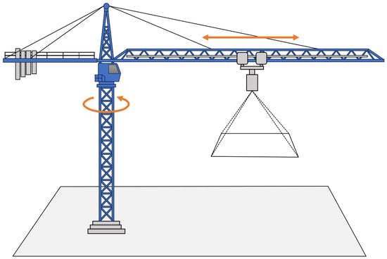
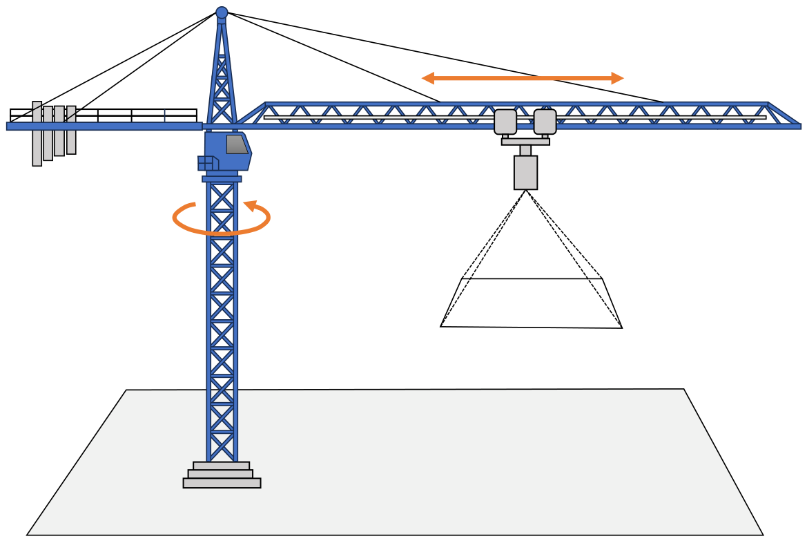
Accurate 3D reconstruction of construction sites provides geometric support for progress monitoring, quantity estimation, and safety-hazard inspection. Tower-crane cameras and surveillance devices have made continuous construction-site imagery increasingly available, enabling low-cost repeated image acquisition for reconstructing active construction areas [1,2,3,4]. Figure 1 shows the tower-crane-mounted image acquisition configuration considered in this study. Unlike controlled benchmark imagery, these image sequences are affected by changing site layouts, uneven texture distribution, local motion, and foreground occlusion.
Figure 1.
Schematic diagram of construction-site image acquisition using a downward-looking camera mounted on a tower crane. The orange circular arrow denotes the slewing motion of the tower crane, and the orange double-headed arrow indicates camera movement along the jib.
Crane hooks and cables are a recurring source of reconstruction errors in such data. They are not part of the static construction scene, but their image features may still enter the reconstruction pipeline. Once retained as valid observations, these occluders can introduce false correspondences, degrade camera registration, and generate erroneous depth responses. During depth-map fusion, these local errors may appear as floating outliers or scattered spurious points in the final dense point cloud. The problem is therefore not limited to foreground segmentation; it is a visibility-related reconstruction failure that affects both sparse and dense stages.
Occlusion and visibility reasoning have been studied in multi-view reconstruction. Early dense Multi-View Stereo (MVS) methods excluded or down-weighted occluded pixels to reduce invalid photometric support [5]. Other methods introduced occluding contours or visibility relations to improve geometric consistency across views [6]. Occlusion-aware masking has also been used in mesh refinement to limit photometric error computation in occluded regions [7]. More recent learning-based MVS methods incorporate visibility modeling into cost aggregation and depth inference [8]. These studies confirm the role of visibility reasoning in robust reconstruction. However, most of them either target general scenes or operate at a limited stage of the reconstruction pipeline. They do not directly provide an automatic way to extract crane-hook occluders from tower-crane imagery and propagate the resulting visibility constraints through both Structure from Motion (SfM) and dense MVS. This setting motivates a reconstruction-aware prompt source and a visibility constraint shared by SfM and dense MVS.
Promptable segmentation offers a possible route for extracting irregular occluders. The Segment Anything Model (SAM) introduced point-, box-, and mask-guided segmentation with strong generalization ability [9]. Segment Anything Model 2 (SAM2) extends this promptable segmentation paradigm to images and videos, which is relevant to temporally collected construction-site imagery [10]. Meanwhile, segmentation-guided MVS methods, such as Segmentation-Driven Deformation Multi-View Stereo (SD-MVS) and Multi-Granularity Segmentation Prior Guided Multi-View Stereo (MSP-MVS), use segmentation priors to guide patch deformation, boundary handling, and multi-granularity matching [11,12]. These studies show that segmentation can regularize dense matching. However, segmentation masks alone do not determine which image regions are harmful to reconstruction. For tower-crane imagery, the missing component is a prompt source that is coupled with geometric failure, rather than only with visual appearance or semantic category.
This paper introduces an occluder-mask-constrained 3D reconstruction framework for tower-crane construction-site imagery. The framework detects adjacent-view geometric anomalies, converts anomaly clusters into prompt points, extracts occluder masks with SAM2, and uses the masks as visibility constraints in reconstruction. The masks are applied before sparse reconstruction to reject occluder-region features. They are also incorporated into Adaptive Patch Deformation Multi-View Stereo (APD-MVS) [13] through matching-cost computation, support-region selection, and depth-map fusion. In this formulation, the mask serves as a reconstruction-validity map: it selects feature observations for SfM and source-view projections for APD-MVS matching and fusion.
The main contributions are summarized as follows:
- 1.
- A geometry-driven prompt generation strategy is proposed for tower-crane imagery. It generates occluder prompt points from adjacent-view geometric anomalies, without requiring additional object detection training data.
- 2.
- An occluder-mask-constrained reconstruction framework is developed. The extracted masks are introduced into sparse feature filtering and APD-MVS-based dense reconstruction, including matching-cost evaluation, valid-anchor selection, and depth-map fusion.
- 3.
- The method is evaluated on three real construction-site datasets. The experiments show improved sparse registration completeness, reduced SfM running time in most cases, and fewer visible spurious points caused by crane hooks in dense point clouds.
2. Related Work
2.1. Image-Based 3D Reconstruction for Construction Sites
Image-based 3D reconstruction provides a practical route for obtaining 3D representations of construction scenes from ordinary image sequences. Compared with laser scanning or other dedicated surveying systems, images acquired by tower-crane cameras, fixed site cameras, mobile devices, or unmanned aerial vehicles can be collected repeatedly with relatively low deployment cost. For this reason, image-based reconstruction is suitable for generating visual and geometric records of active construction areas, especially when continuous or repeated data acquisition is already available on site. Zheng et al. reviewed the key components of vision-based 3D reconstruction, including image acquisition, feature matching, camera pose estimation, and dense reconstruction [1]. For tower-crane image sequences, Lu et al. investigated image selection and 3D reconstruction by combining image hash features and motion trajectory constraints, showing that tower-crane imagery can be used as reconstruction input rather than only as visual monitoring records [2]. Xue et al. reviewed image-based building reconstruction in construction applications, and Sun et al. investigated near-real-time construction-site reconstruction from surveillance-camera imagery [3,4]. Recent learning-based SfM–MVS studies have introduced deep feature matching, depth estimation, attention mechanisms, and neural volume rendering to improve reconstruction robustness under challenging matching conditions [14,15]. However, these works mainly enhance the reconstruction pipeline itself and do not explicitly address foreground occluders such as crane hooks and cables in tower-crane imagery.
From a technical perspective, most image-based reconstruction pipelines follow a sparse-to-dense process. SfM first estimates camera poses and sparse 3D points from cross-view feature correspondences, geometric verification, triangulation, and bundle adjustment (BA) [16]. MVS then estimates dense depth maps or dense point clouds from registered images by evaluating cross-view photometric consistency [17]. Classical MVS methods, including Patch-based Multi-View Stereo (PMVS), Gipuma, and COLMAP-style MVS, rely on local photometric consistency, view selection, propagation, filtering, and geometric consistency to recover dense geometry [17,18,19]. More recent methods further improve dense matching in weakly textured or ambiguous regions. APD-MVS, for example, adaptively deforms local patches and expands the support region around unreliable pixels to improve textureless-resilient MVS [13]. Neural rendering and Gaussian-splatting-based reconstruction have also introduced new representations for scene reconstruction. For example, Stereo Gaussian Splatting (Stereo-GS) performs online 3D Gaussian Splatting reconstruction from stereo image streams, and planar-guided Gaussian Splatting incorporates geometric priors and SAM-family masks to improve reconstruction in texture-poor regions [20,21]. Although these methods improve reconstruction quality from the perspectives of matching, representation, or geometric regularization, most of them assume that the input observations mainly belong to the target scene. In tower-crane construction imagery, this assumption is often violated because crane hooks and cables may appear between the camera and the construction area. If such foreground occluder observations are retained, they may enter feature matching and camera registration in the sparse stage and may further produce spurious points during dense matching and fusion. Therefore, construction-site reconstruction from tower-crane imagery requires not only robust SfM–MVS algorithms but also a mechanism for identifying and excluding foreground occluder observations before and during reconstruction.
2.2. Visual Object Extraction
Visual object extraction aims to obtain the spatial extent of target objects from images, and its outputs may include bounding boxes, instance masks, semantic masks, or object-level pixel regions. Supervised object detection and segmentation methods have provided effective solutions for predefined visual categories. For example, Mask2Former unifies semantic segmentation, instance segmentation, and panoptic segmentation within a masked-attention mask-transformer architecture [22]. Detection Transformer (DETR) with Improved DeNoising Anchor Boxes (DINO) improves DETR-style end-to-end object detection through denoising training and improved anchor-box design [23]. You Only Look Once version 10 (YOLOv10) further develops real-time end-to-end object detection by optimizing the accuracy–efficiency trade-off of the YOLO series [24]. These methods can achieve strong performance when sufficient annotated data are available for the target categories. However, this condition is difficult to satisfy for occluder extraction from construction-site images. The foreground occluders in tower-crane imagery may include crane hooks, cables, lifting components, temporary structures, and other irregular objects, and no dedicated annotated dataset is available for these diverse occluder categories. Therefore, training a closed-set supervised detector or segmenter would require additional annotation work and may still generalize poorly across different sites, camera viewpoints, illumination conditions, occluder appearances, and image qualities.
When task-specific labeled data are unavailable, open-set, unsupervised, and promptable methods provide a more flexible route for visual object extraction. Cut and Learn (CutLER) uses self-supervised features to generate coarse object masks and trains a localization model, enabling object detection and instance segmentation without human annotations [25]. Grounding DINO introduces language-guided open-set object detection and can localize objects specified by category names or referring expressions [26]. X-Decoder unifies pixel-level segmentation and language-token prediction in a generalized decoding framework, supporting open-vocabulary segmentation and referring segmentation [27]. Nevertheless, for construction-site occluder extraction, category-level semantics alone may be unreliable because occluders vary greatly in type and appearance, and construction-site images are often affected by low resolution, motion blur, poor illumination, and background clutter. Prompt-guided mask extraction is therefore a more suitable route. Segment Everything Everywhere All at Once (SEEM) develops a promptable and interactive segmentation interface that supports diverse prompts, such as points, boxes, scribbles, masks, and text [28]. In the promptable segmentation line, the SAM formulates segmentation as a prompt-driven task and generates masks from points, boxes, or masks with strong zero-shot transfer ability [9]. High-Quality Segment Anything Model (HQ-SAM) improves the mask quality of the SAM for objects with complex structures while preserving its promptable design and zero-shot generalization [29]. SAM2 further extends promptable visual segmentation from images to videos by introducing a streaming-memory design for real-time video processing [10]. However, manually specifying visual prompts is labor-intensive and impractical for large image sequences. Consequently, reliable automatic prompt generation is essential for obtaining stable occluder masks in complex construction-site imagery.
2.3. Occlusion Handling and Reconstruction Constraints
Existing occlusion-handling approaches address visibility reasoning from complementary perspectives. Visibility-aware MVS methods exclude, down-weight, or explicitly model source-view observations that are unlikely to support the same surface point [5,6,8]. Occlusion-aware masking restricts photometric computation during mesh refinement [7]. Segmentation-guided MVS methods introduce semantic or instance priors into dense matching, patch deformation, or boundary handling [11,12]. Dynamic-scene mapping provides a related line of research: dynamic simultaneous localization and mapping (DynaSLAM) combines multi-view geometry and learned detection for dynamic-object suppression and background inpainting, while MaskFusion uses instance-level semantic masks to recognize, track, and reconstruct independently moving red–green–blue-depth (RGB-D) objects [30,31]. Neural-rendering methods address transient foreground content through alternative scene representations; for example, Neural Radiance Fields in the Wild (NeRF-W) introduces a transient component for unconstrained photo collections, and Gaussian-splatting methods incorporate geometric or segmentation priors into explicit radiance-based representations [20,21,32]. At the pipeline level, visibility cues can therefore originate from photometric consistency, geometric occlusion, motion cues, semantic priors, or learned source-view reliability, and they may be introduced at different stages of scene reconstruction.
Recurring crane-hook occlusion affects both sparse and dense reconstruction. The proposed framework converts spatially concentrated adjacent-view geometric anomalies into segmentation prompts and propagates the resulting occluder-validity map through the sparse-to-dense pipeline.
3. Methodology
3.1. Overview of the Proposed Framework
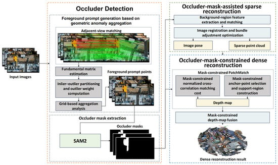
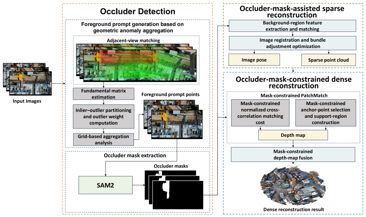
Figure 2 shows the overall pipeline of the proposed occluder-mask-constrained 3D reconstruction framework. The framework consists of four main modules: geometric-anomaly-based prompt generation, SAM2-based occluder mask extraction, occluder-mask-assisted sparse reconstruction, and occluder-mask-constrained dense reconstruction.
Figure 2.
Overall workflow of the proposed method.
Adjacent-view feature matching and robust epipolar verification identify geometric anomalies relative to the dominant construction-scene geometry. Their spatially aggregated clusters provide point prompts for SAM2-based occluder segmentation.
The resulting pixel-validity maps are shared by the sparse and dense stages: they filter SfM observations and constrain APD-MVS matching-cost computation, support-region selection, and depth-map fusion. The workflow outputs a dense point cloud for experimental evaluation.
3.2. Geometric Anomaly Information Acquisition
The prompt generation module identifies image regions that violate the dominant adjacent-view geometry. In neighboring tower-crane frames, most static construction-scene points follow a stable epipolar relation. By contrast, crane hooks and cables may produce inconsistent matches because of local occlusion, relative motion, or strong depth discontinuity. The proposed method therefore uses the spatial aggregation of these inconsistent matches to generate point prompts for occluder segmentation.
3.2.1. Adjacent-View Geometry and Geometric Outlier Detection
Let two adjacent images be denoted as and . After feature extraction and matching, the initial correspondence set is defined as
where and are the homogeneous coordinates of the k-th matched feature in and , respectively. The term denotes the LightGlue matching confidence after match filtering [33]. The score is clipped to before anomaly weighting, so the confidence contribution remains bounded across adjacent-image pairs.
For a correspondence that follows the dominant adjacent-view geometry, the epipolar constraint is
where is the fundamental matrix between and .
The initial correspondences may contain ordinary mismatches and occluder-related matches. A robust estimator is therefore used to recover the epipolar model mainly supported by the construction-scene region. This study adopts Universal Sample Consensus (USAC) with Marginalizing Sample Consensus (MAGSAC), implemented as USAC_MAGSAC, for fundamental matrix estimation [34,35]. The estimated model is expressed as
where denotes the robust model score used by the MAGSAC framework.
Based on , the initial correspondences are divided into an inlier set and an outlier set :
The inliers mainly support the dominant construction-scene geometry. The outlier set may include ordinary mismatches, weak-texture matches, and local image noise in addition to occluder-related observations. Spatial concentration is therefore used to identify candidate crane-hook or cable regions, while isolated outliers receive limited influence.
3.2.2. Geometric Anomaly Weighting and Prompt Point Generation
For each outlier correspondence, the geometric deviation from the estimated dominant geometry is measured using the symmetric epipolar distance:
The outlier weight is defined by combining the matching confidence and the truncated geometric deviation:
where is the normalization and truncation threshold for the geometric deviation. For the reported implementation, is set to the 8-pixel geometric threshold used during robust epipolar verification. Since is bounded in , a lower-confidence correspondence with a larger deviation obtains a higher weight. The truncation term avoids excessive influence from a small number of extremely large deviations.
The outlier locations are projected onto the image plane of the reference image and aggregated using regular grid cells. For the g-th grid cell, let be the set of outlier correspondences whose reference-view points fall inside this cell. The anomaly score of the cell is
Cells with larger contain stronger and more concentrated geometric anomalies. Candidate cells are ranked according to their anomaly scores and outlier distributions. For each selected non-empty cell, the prompt point is computed as the weighted centroid of the outlier locations:
where is the two-dimensional coordinate of the k-th outlier in the reference image.
Grid-based centroid estimation suppresses isolated mismatches and moves the prompt toward the dominant anomaly cluster. The generated prompt points are then used for SAM2-based occluder mask extraction.
3.2.3. Prompt-Guided Mask Extraction and Validity Map Definition
The geometric prompt points provide sparse location cues for potential occluder regions. SAM2 is used as a prompt-guided segmentation module to convert these points into pixel-level occluder masks [10]. The Segment Anything Model 2.1 (SAM2.1) predictor configuration used in each experiment is reported in Section 4.2. For each image, the prompt points generated from adjacent-view geometric anomalies are fed into SAM2 as positive foreground prompts, and SAM2 predicts a binary mask aligned with the original image. Before validity-map construction, the predicted masks are combined with a sequence-level common-border mask and screened using simple abnormal-response rules. The common-border mask is obtained by intersecting boundary-connected border candidates across the image sequence. All-black masks and masks dominated by top-left or edge-highlighted regions are rejected. This post-processing removes camera-frame borders and abnormal segmentation responses from the reconstruction-valid image regions. The benchmark-specific border-candidate threshold and sequence length are reported in Section 4.2 and Appendix A (Table A1).
The prompts are derived from adjacent-view geometric inconsistency, so prompt selection is directly linked to regions that disturb multi-view reconstruction.
The segmentation result is converted into a binary validity map for subsequent reconstruction constraints. For image , the validity map is defined as
where is a pixel location, denotes the valid construction-scene region, and denotes the occluder region. Pixels with are termed mask-valid, whereas pixels with are termed mask-invalid. The same terminology is used below for observations, projections, anchors, and candidate 3D points according to their associated pixel locations.
For a reference-view pixel in image and its corresponding source-view location in image , the mask-based visibility indicator is defined as
The indicator is used in sparse correspondence filtering, dense matching, and depth-map fusion to enforce cross-view mask consistency.
3.3. Occluder-Mask-Constrained Sparse Reconstruction
The occluder masks are first applied before sparse reconstruction to filter feature observations before correspondence construction, geometric verification, and BA. The SfM stage retains the standard reprojection-error minimization framework [16]. The validity map determines the feature observations supplied to correspondence construction, geometric verification, triangulation, and BA.
3.3.1. Mask-Based Feature and Correspondence Filtering
For a detected feature point at pixel in image , the feature is retained only if
For a candidate correspondence between image and image , let and be the matched pixel locations. The correspondence is accepted only when
The accepted correspondences are then used for geometric verification, image registration, and sparse point triangulation.
3.3.2. Mask-Constrained SfM Objective
After mask-based filtering, the observations entering BA are represented by the following mask indicator. For the observation of 3D point in image ,
where is the corresponding image observation.
The resulting SfM objective is written as
where denotes the camera parameters of image , denotes the ℓ-th 3D point, is the projection function, and is the observation set.
Equation (14) expresses BA over the mask-valid observation set and makes the observation-selection mechanism explicit.
3.4. Occluder-Mask-Constrained Dense Reconstruction
After sparse reconstruction, the same occluder masks are introduced into APD-MVS-based dense reconstruction. The constraints act on matching-cost computation, deformable PatchMatch support selection, and depth-map fusion. They restrict which pixels, projections, anchors, and candidate 3D points can support dense reconstruction.
3.4.1. APD-MVS Plane Hypothesis and Mask-Constrained Matching Cost
APD-MVS is a PatchMatch-based MVS method that uses adaptive patch deformation to improve depth estimation in difficult regions [13]. For a reference-view pixel , the local plane hypothesis is represented as
where and denote the local plane normal and depth parameter, respectively.
Given a plane hypothesis, the reference patch centered at is projected to source views. Let be the reference patch centered at , and let be the corresponding patch projected to source view j under the plane hypothesis . The original single-view matching cost is defined by Normalized Cross-Correlation (NCC):
Let be the projection of the reference pixel into source view j under the current plane hypothesis. The mask-constrained single-view cost is defined as
In implementation, source-view observations with are excluded from cost aggregation. If no valid source-view observation remains for a plane hypothesis, the hypothesis is rejected.
Let denote the aggregated mask-constrained matching cost over valid source views. The plane hypothesis search is written as
3.4.2. Mask-Constrained Support Region in Deformable PatchMatch
For unreliable pixels, APD-MVS uses deformable PatchMatch to evaluate a plane hypothesis with additional anchor pixels. To avoid support-region propagation from occluder pixels, the valid anchor set is defined as
The corresponding deformable cost is computed over this valid anchor set:
where controls the balance between the center-pixel term and the anchor-based support term. The term denotes the mask-constrained patch matching cost used in the APD-MVS support-region formulation. In implementation, if no valid anchor remains, the support term is skipped and only the mask-constrained center-pixel term is used.
The mask constraint therefore acts on both center-pixel evaluation and support-region construction.
3.4.3. Mask-Consistent Depth-Map Fusion
Finally, mask consistency is imposed during depth-map fusion. After depth maps are estimated, let pixel in reference view and its depth be back-projected to a 3D point . Let be the projection of in source view . For this source view, the candidate point is allowed to enter the final point cloud only when the mask consistency condition is satisfied:
The candidate point must also satisfy the geometric consistency checks used during fusion:
Here, and denote the reprojection location and returned depth after projecting from the source view back to the reference view. The thresholds , , and correspond to reprojection error, relative depth difference, and normal-angle difference, respectively.
Only candidates satisfying both mask and geometric consistency are fused into the final dense point cloud.
4. Experiments and Results
4.1. Datasets, Hardware, and Evaluation Protocol
Three real construction-site image datasets were used to evaluate the proposed method. They are denoted as Scene A, Scene B, and Scene C. All images were captured by monitoring cameras mounted on tower-crane trolleys, with the optical axes approximately pointing downward toward the construction areas. The datasets cover different site locations, tower-crane heights, sequence lengths, scene textures, and recurring foreground-occluder appearances. Table 1 summarizes the main dataset characteristics. Scene A contains 391 images collected from a construction site in Sanming, Fujian Province, at a tower-crane height of 100 m. Scene B contains 308 images collected from a construction site in Zhongshan, Guangdong Province, at a height of 20 m. Scene C contains 276 images collected from a construction site in Xiamen, Fujian Province, at a height of 50 m. All images were calibrated and distortion-corrected before reconstruction. Since the images were collected in temporal order, adjacent-view matching refers to feature matching between temporally neighboring frames.
Table 1.
Construction-site image datasets used in the experiments.
The experimental evaluation is organized at two levels. First, all three scenes are used to assess the applicability of the proposed method under different construction-site conditions. This cross-scene evaluation focuses on sparse-reconstruction behavior, including registration completeness, sparse-point generation, track stability, reprojection error, and SfM runtime. Second, the 308-image Scene B sequence is selected as the representative controlled benchmark. It is used for pixel-level mask-quality evaluation, baseline comparison, stage-wise ablation studies, grid-aggregation analysis, runtime accounting, resource-consumption analysis, and aligned dense-point-cloud visualization. Using a fixed representative sequence ensures that the compared methods are evaluated under consistent image, reconstruction, and visualization settings.
Sparse reconstruction is evaluated using the number of registered images, the number of sparse 3D points, average track length, average reprojection error, and SfM runtime. Occluder-mask quality is evaluated on a manually annotated validation subset using intersection over union (IoU)-based metrics, including mean IoU (mIoU), mean Dice score (mDice), mean precision (mPrecision), mean recall (mRecall), micro IoU, and pixel accuracy. Dense reconstruction is assessed through aligned local point-cloud comparisons, with particular attention to floating outliers and scattered spurious points associated with recurring foreground occluders. High-precision reference point clouds are unavailable for the tested active construction sites. Therefore, the dense-stage comparisons are interpreted as visual evidence of occluder-induced artifact suppression rather than as quantitative proof of improved absolute dense-reconstruction accuracy.
All experiments were conducted on a workstation running Ubuntu 22.04.5 Long-Term Support (LTS). The workstation is equipped with an Intel Core i9-14900HX central processing unit (CPU) with 24 cores and 32 threads and an NVIDIA GeForce RTX 3090 graphics processing unit (GPU) with 24 GB of GPU memory. The software environment and benchmark-specific implementation settings are reported in Section 4.2 and Appendix A.
4.2. Implementation Details
The three-scene demonstrations and the controlled Scene B benchmark use the SAM2.1-Hiera-Large predictor with the sam2.1_hiera_l.yaml configuration. The controlled benchmark was conducted on the 308-image Scene B sequence at a resolution of pixels. The proposed method and the grid-aggregation ablation used image-predictor inference, whereas the manually prompted SAM2.1 reference used video propagation with interactive prompts. The main parameters of the representative benchmark are reported in Appendix A (Table A1).
The front end used SuperPoint features with LightGlue matching [33,36] and MAGSAC-based epipolar verification. Matcher confidence was bounded to before anomaly weighting, and the 8-pixel geometric threshold was used for robust partitioning and deviation truncation. Spatially aggregated geometric anomalies were converted into positive foreground prompts for SAM2.1. The resulting masks were post-processed and introduced into the SfM stage implemented with COLMAP 3.9.1 and into APD-MVS (official Computer Vision and Pattern Recognition (CVPR) 2023 GitHub implementation; https://github.com/whoiszzj/apd-mvs; accessed on 28 June 2026).
For the representative Scene B benchmark, the common-border mask was extracted from the 308-frame intersection of pixels satisfying and was restricted to boundary-connected regions. The same benchmark-specific setting is listed in Appendix A (Table A1).
Each masking condition used a separately initialized COLMAP database. Feature extraction and matching were rerun for each condition.
4.3. Geometry-Driven Prompts and Mask Quality
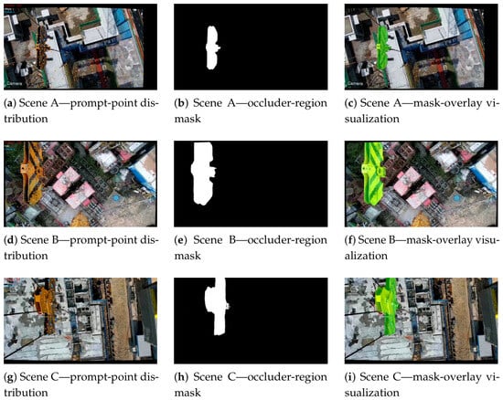
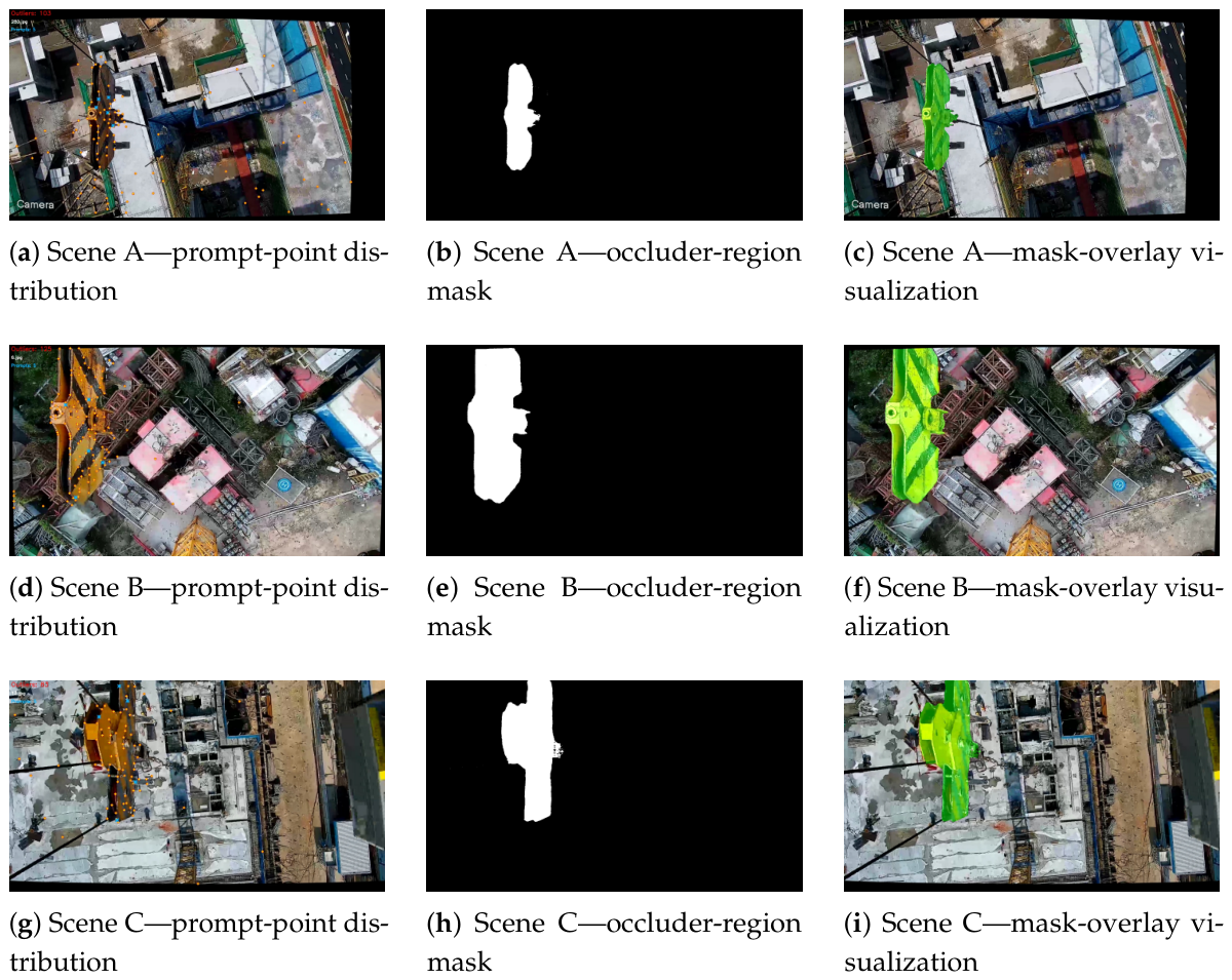
Figure 3 presents representative prompt and mask extraction results for the three construction scenes. Grid-based aggregation concentrates prompt selection on anomaly regions supported by multiple neighboring matches. This spatial aggregation suppresses isolated outliers caused by weak texture, ordinary mismatches, local image noise, or repeated structures. SAM2.1 then converts the representative prompts into pixel-level masks. The automatic geometry-driven branches in the controlled mask-quality evaluation use the SAM2.1-Hiera-Large predictor reported in Table A1.
Figure 3.
Geometry-driven prompts and occluder masks in three construction scenes. Yellow points denote geometric outliers, blue points denote SAM2 prompts, and the masks are shown alone and overlaid on the original images.
Table 2 reports pixel-level mask quality on a manually annotated validation subset from the representative sequence. The manually prompted SAM2.1 result provides an interactive reference for mask quality.
Table 2.
Occluder-mask quality on a manually annotated validation subset.
The proposed automatic method achieves an mIoU of 0.640 and an mDice of 0.724. Its mPrecision of 0.816 and mRecall of 0.725 indicate that the geometry-driven prompts provide usable occluder coverage without excessive foreground expansion. The remaining gap to the manually prompted SAM2.1 reference quantifies the effect of replacing direct human guidance with automatic geometry-driven prompts.
4.4. Sparse Reconstruction Evaluation and Scene C Diagnosis
Table 3 reports the sparse reconstruction results with and without occluder-mask assistance for all three scenes.
Table 3.
Influence of occluder masks on sparse reconstruction results.
For Scenes A and B, mask-based filtering reduces reprojection error and SfM runtime while maintaining or improving registration completeness. Scene C shows the strongest effect. The standard SfM pipeline registers 35 of 276 images, whereas foreground filtering recovers the complete 276-image sequence and increases the sparse-point count from 7520 to 45,871. The average track length also increases from 3.821 to 4.561.
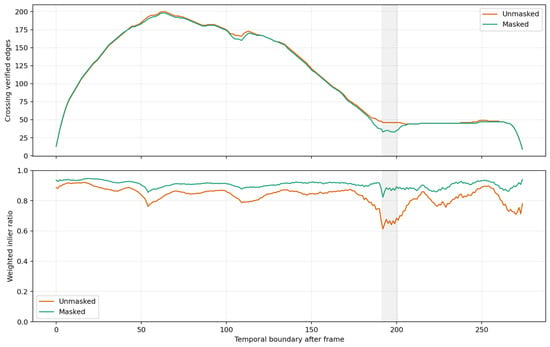
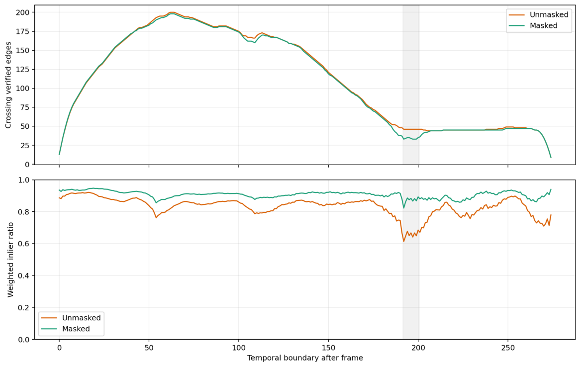
The prompt and mask visualizations in Figure 3 show that the retained anomaly clusters are concentrated around recurring foreground occluders. For Scene C, Table 4 and Figure 4 jointly diagnose sequence-level connectivity and the weakest temporal boundary. The first three rows of Table 4 show that both two-view graphs contain all 276 images in one connected component; thus, mask filtering does not reduce image-level graph coverage or split the sequence. The number of verified edges decreases slightly from 2805 to 2770, while the weighted inlier ratio increases from 89.70% to 94.74%. This combination indicates selective removal of lower-consistency correspondences rather than a general loss of connectivity. At the boundary between frames 192 and 193, cross-boundary verified edges decrease from 46 to 33, whereas the boundary weighted inlier ratio increases from 61.38% to 82.29%. Figure 4 visualizes the same trade-off across the sequence, with the largest improvement occurring in the shaded boundary interval. Most importantly, the final row of Table 4 shows that the largest registered component after incremental mapping increases from 35 to 276 images. Therefore, Table 4 links preserved graph coverage and improved correspondence consistency to the observed recovery of the complete Scene C sequence, supporting the conclusion that mask filtering enables more complete sparse registration.
Table 4.
Compact registration-graph diagnosis for Scene C under the sequence-matching setting.
Figure 4.
Temporal-boundary connectivity and weighted inlier ratio for Scene C. The grey shaded interval marks the temporal boundary between frames 192 and 193.
4.5. Representative Baseline Comparison
The representative 308-image sequence is evaluated with explicit and implicit baselines to assess the relative contribution of geometry-driven prompts and alternative foreground-handling strategies. You Only Look Once version 8 (YOLOv8) bounding-box removal is an explicit detector-based baseline [37]. The manually prompted SAM2.1 result provides an interactive reference. The Segment Anything Model 3 (SAM3) text-prompt baseline uses the open-vocabulary prompt hook [38]. Visibility-Aware Multi-View Stereo Network (Vis-MVSNet) is included as a visibility-aware learning-based dense-reconstruction baseline using known camera poses.
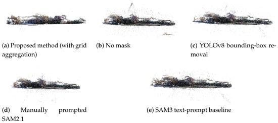
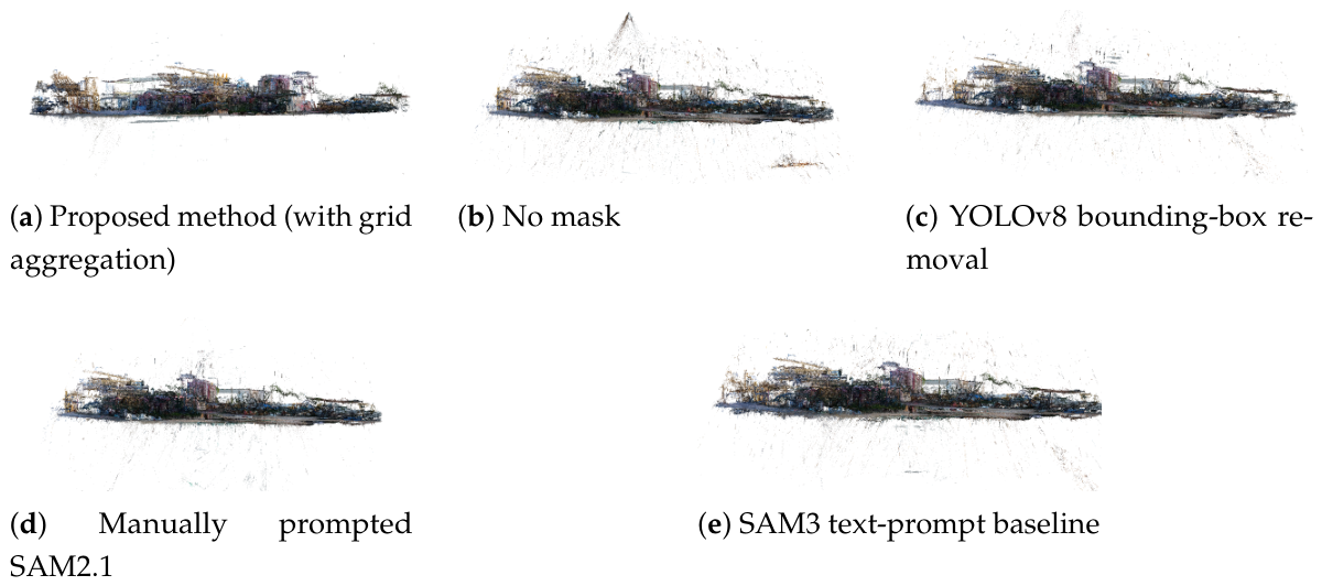
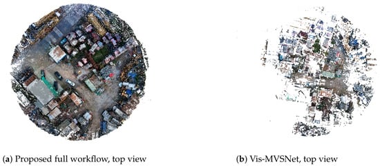
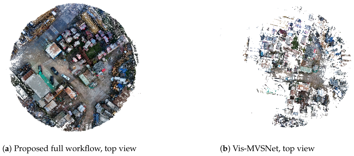
Detailed baseline configurations and parameter-selection protocols are provided in Appendix B (Table A2). For the explicit-mask methods, the Scene B images, common-border constraint, COLMAP settings, and APD-MVS settings were held fixed; only the mask-generation module changed between methods. The 25 manually annotated Scene B frames were used only for final mask-quality evaluation and not for threshold sweeping. The mask-quality results in Table 2 show that geometry-driven prompts achieve higher overlap quality than YOLOv8 bounding-box removal and the SAM3 text-prompt baseline on the annotated validation subset. Figure 5 provides aligned local point-cloud views for the proposed method, the no-mask reconstruction, YOLOv8 bounding-box removal, manually prompted SAM2.1, and the SAM3 text-prompt baseline. Compared with the no-mask baseline, the proposed method visibly suppresses hook-induced floating artifacts while retaining more visible main-scene structure in the aligned point-cloud comparison. Figure 6 further compares the proposed full workflow with Vis-MVSNet from a top-view perspective. In this aligned top-view visualization, the proposed workflow retains more visible scene structure than the Vis-MVSNet result.
Figure 5.
Local dense-point-cloud comparison among representative foreground-removal strategies.
Figure 6.
Top-view comparison between the proposed full workflow and Vis-MVSNet.
4.6. Ablation Studies
4.6.1. Sparse- and Dense-Stage Masking
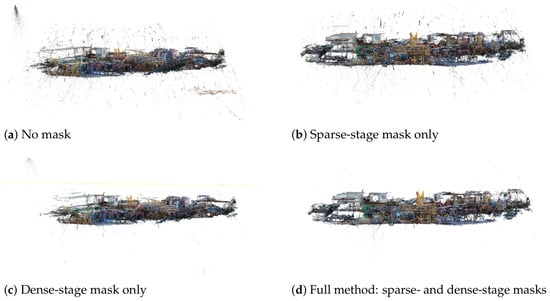
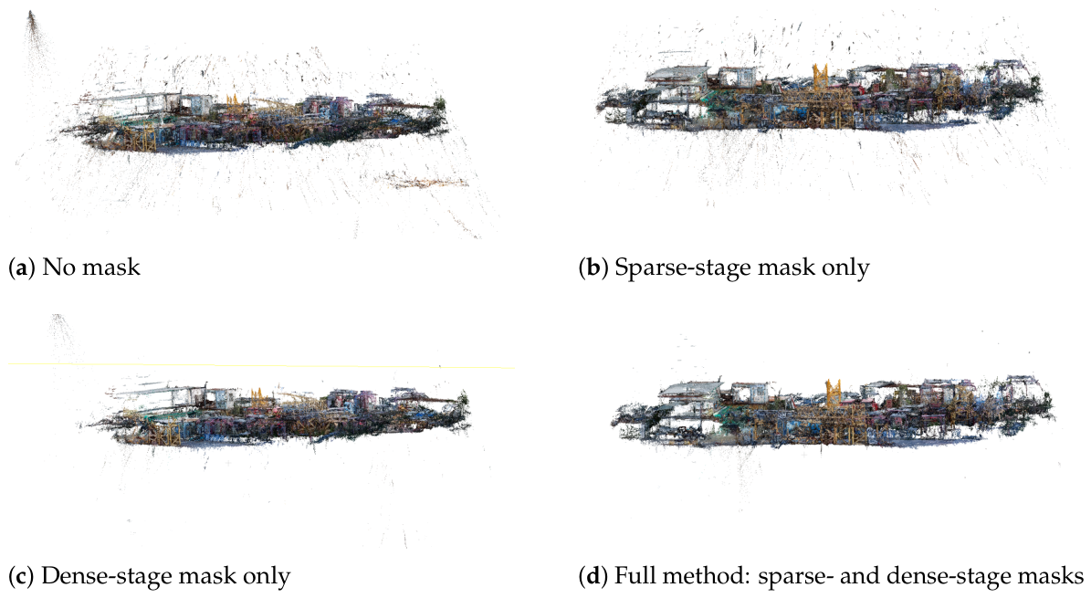
Table 5 reports stage-wise masking results. Dense-stage masking toggles matching-cost evaluation, valid-anchor selection, and depth-map fusion. Each condition started from a separate empty COLMAP database; feature extraction and matching were rerun. Figure 7 presents the aligned local point-cloud comparison.
Table 5.
Ablation study of sparse- and dense-stage masking on the representative sequence. Runtime columns report SfM, depth estimation, fusion, and their sum; the reported total excludes frontend preprocessing.
Figure 7.
Aligned local dense-point-cloud comparison for the sparse- and dense-stage mask ablation.
Sparse-stage masking reduces visible occluder-induced artifacts. Dense-stage masking removes more floating artifacts but retains less visible scene structure. Among the tested ablation settings, the full workflow produces the fewest visually identifiable artifacts while retaining more visible scene structure than the dense-stage-mask-only condition.
4.6.2. Effect of Grid-Based Aggregation
Table 6 evaluates grid-based anomaly aggregation. Without aggregation, all 30,668 geometric outliers are directly treated as positive prompts. This increases the average raw foreground-mask ratio from 0.098 to 0.569 and causes excessive foreground capture. After post-processing, the number of retained non-border masks decreases from 28 to 1, and mIoU decreases from 0.640 to 0.283.
Table 6.
Ablation study of grid-based anomaly aggregation.
4.7. Runtime and Resource Consumption
For the representative 308-image sequence, the measured workflow time is 01:11:28.38 for the proposed method and 01:36:10.59 for the no-mask SfM/APD-MVS baseline. All reported runtimes are directly measured single-GPU wall-clock times on the workstation described above. Table 7 reports frontend preprocessing, SfM, depth estimation, and fusion times; its workflow total includes frontend preprocessing. Frontend preprocessing accounts for approximately 3.2% of the proposed workflow total. Mask constraints exclude mask-invalid pixels and projections from dense matching and fusion.
Table 7.
Measured runtime and resource consumption for the representative proposed workflow and no-mask baseline. The workflow total includes frontend preprocessing.
The dense-stage system-memory peaks are 14,970.2 mebibytes (MiB) for the proposed method and 14,649.0 MiB for the no-mask baseline. The corresponding CPU high-water marks are 13,110.9 MiB and 13,012.6 MiB.
The current implementation performs offline reconstruction. For the representative 308-image sequence, geometry-anomaly detection, prompt generation, SAM2 image-predictor inference, and mask post-processing require 00:02:15.65. SfM mapping, APD-MVS depth estimation, and depth-map fusion account for most of the runtime. Potential deployment optimizations include keyframe selection, change-detection-triggered reconstruction, incremental SfM, task queues, and block-wise depth-map fusion.
4.8. Dense Reconstruction Visualization
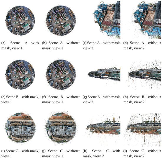
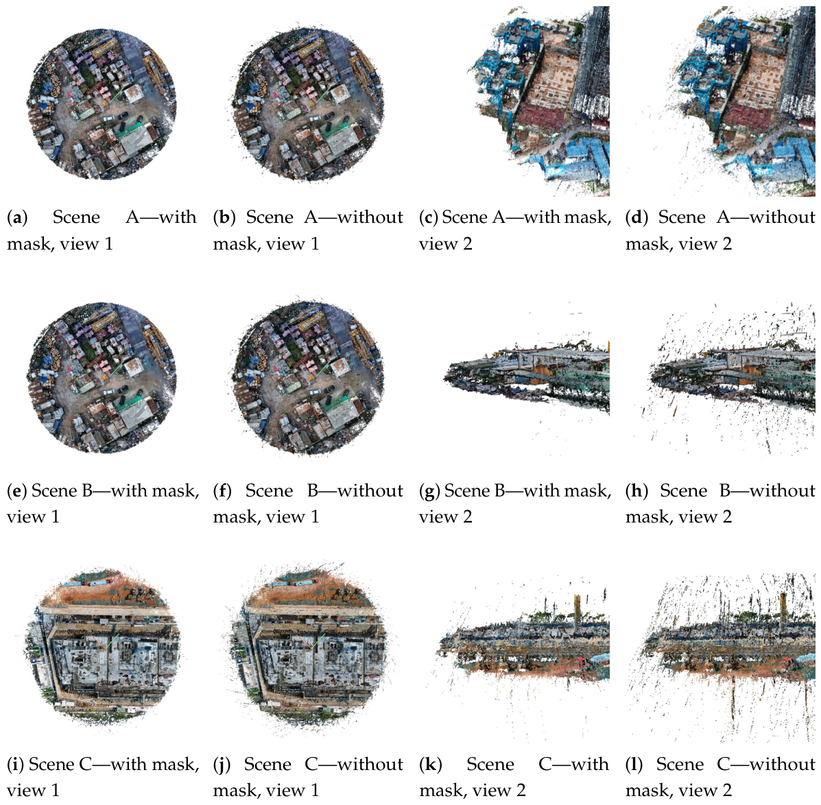
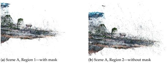
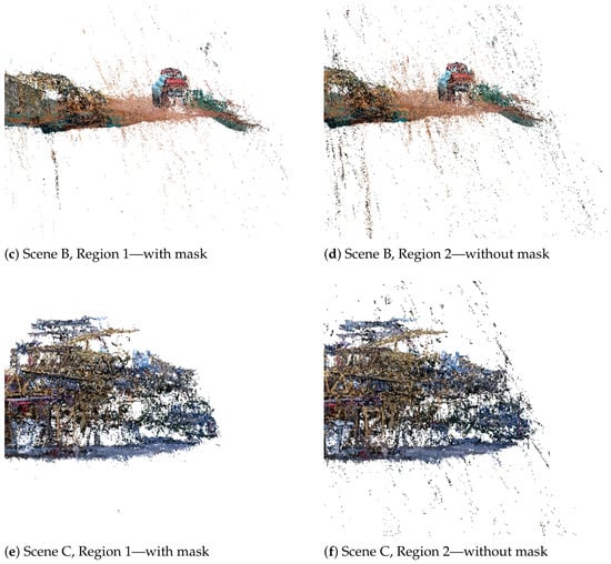
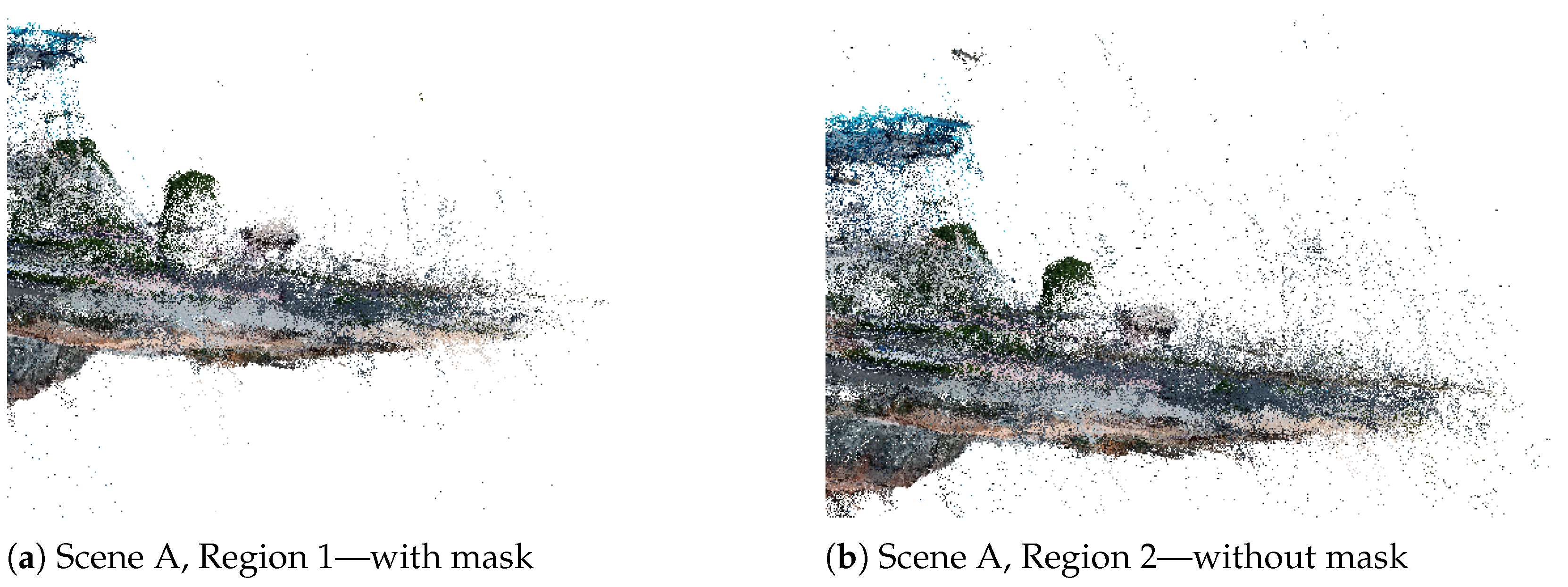
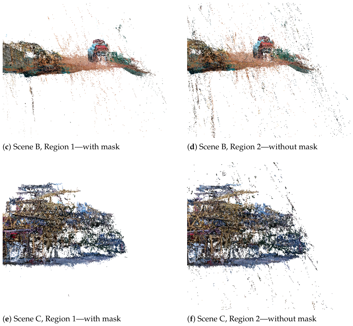
Figure 8 compares dense point clouds reconstructed with and without occluder-mask constraints in the three scenes. Figure 9 provides enlarged comparisons using matched viewpoints and crop ranges within each scene.
Figure 8.
Dense point-cloud comparison with and without occluder-mask constraints in three construction scenes.
Figure 9.
Local zoomed-in comparison of occluder-induced dense-point-cloud artifacts. In each row, the left subfigure shows reconstruction with mask constraints and the right subfigure shows reconstruction without mask constraints.
Introducing occluder masks reduces visually identifiable floating outliers and scattered spurious points in all three scenes. The effect is most pronounced in Scene C, where vertically distributed artifacts around the crane-hook region are substantially reduced after mask-constrained reconstruction. These dense comparisons remain qualitative because reference point clouds are unavailable.
5. Discussion
5.1. Mechanism and Applicability
The binary validity-map formulation matches the implemented reconstruction operations and the available pixel-level mask annotations. A future probabilistic extension could replace the hard validity indicator with calibrated reliability weights when uncertainty supervision or repeated reference measurements are available.
5.2. Limitations and Future Work
The tested datasets cover three active construction sites with different tower-crane heights, image counts, scene textures, and recurring occluder appearances.
Directly using all raw geometric outliers as positive prompts leads to excessive foreground capture. The method remains sensitive to overlapping occluders, thin cables, small distant components, low-resolution imagery, nighttime illumination, motion blur, weak texture, repeated structures, and ambiguous SAM2 boundaries. Future work will address broader acquisition conditions, reference geometry for quantitative dense-stage assessment, temporal consistency, and confidence-aware mask refinement.
6. Conclusions
This paper proposed an occluder-mask-constrained 3D reconstruction framework for tower-crane construction-site imagery. Spatially aggregated adjacent-view geometric anomalies are converted into SAM2.1 prompts, and the resulting occluder masks are propagated as shared pixel-validity constraints through sparse feature filtering, APD-MVS matching-cost evaluation, support-region selection, and depth-map fusion.
Experiments on three real construction-site datasets show improved sparse-registration completeness and fewer visually identifiable occluder-induced artifacts. In Scene C, the number of registered images increases from 35 to 276. On the representative 308-image Scene B benchmark, the proposed method achieves an mIoU of 0.640 and an mDice of 0.724, while reducing the measured workflow time from 01:36:10.59 to 01:11:28.38. Controlled ablations confirm the importance of grid-based anomaly aggregation and joint sparse- and dense-stage masking. Since high-precision reference point clouds are unavailable, the dense-stage results should be interpreted as visual evidence of artifact suppression rather than proof of improved absolute reconstruction accuracy. Future work will address broader acquisition conditions, reference geometry for quantitative dense-stage assessment, temporal consistency, and confidence-aware mask refinement.
Author Contributions
Conceptualization, C.Y., S.Z., Q.Y., Q.H. and R.Z.; methodology, Q.H., R.Z. and C.Y.; software, Q.H. and C.Y.; validation, Q.H., R.Z. and C.Y.; formal analysis, C.Y., Q.H. and R.Z.; investigation, Q.H. and R.Z.; resources, Q.Y. and S.Z.; data curation, Q.H., R.Z. and C.Y.; writing—original draft preparation, C.Y., Q.H. and R.Z.; writing—review and editing, C.Y., Q.Y. and S.Z.; visualization, Q.H. and R.Z.; supervision, C.Y., Q.Y. and S.Z.; project administration, Q.Y. and S.Z. All authors have read and agreed to the published version of the manuscript.
Funding
This research received no external funding.
Institutional Review Board Statement
Not applicable.
Informed Consent Statement
Not applicable.
Data Availability Statement
The data presented in this study are available from the corresponding author upon reasonable request. The data are not publicly available due to construction-site project confidentiality and data-use restrictions, and any access is subject to approval by the participating construction projects.
Conflicts of Interest
The authors declare no conflicts of interest.
Appendix A. Implementation Parameter Details
The key implementation parameters for the representative 308-image benchmark are reported in Table A1.
Table A1.
Key implementation parameters for the representative 308-image benchmark.
Appendix B. Baseline Configuration Details
The configurations for the representative 308-image Scene B baselines are reported in Table A2. The table distinguishes fixed implementation settings from the limited parameter-selection steps used for YOLOv8s and the SAM3 text-prompt baseline. The 25 manually annotated Scene B frames were reserved for final mask-quality evaluation and were not used for threshold selection.
Table A2.
Configuration details for the representative 308-image Scene B baselines.
References
- Zheng, T.; Huang, S.; Li, Y.; Feng, M. Key Techniques for Vision Based 3D Reconstruction: A Review. Acta Autom. Sin. 2020, 46, 631–652. (In Chinese) [Google Scholar] [CrossRef]
- Lu, Y.; Zhang, X.; Zhong, T. Intelligent Selection and 3D Reconstruction Method for Tower-Crane Multi-View Images by Fusing Image Hash Features and Motion Trajectory Constraints. J. Build. Struct. 2025, 46, 188–197. (In Chinese) [Google Scholar]
- Xue, J.; Hou, X.; Zeng, Y. Review of Image-Based 3D Reconstruction of Building for Automated Construction Progress Monitoring. Appl. Sci. 2021, 11, 7840. [Google Scholar] [CrossRef] [Scilit]
- Sun, A.; An, X.; Li, P.; Lv, M.; Liu, W. Near Real-Time 3D Reconstruction of Construction Sites Based on Surveillance Cameras. Buildings 2025, 15, 567. [Google Scholar] [CrossRef] [Scilit]
- Kang, S.B.; Szeliski, R.; Chai, J. Handling Occlusions in Dense Multi-View Stereo. In Proceedings of the IEEE Conference on Computer Vision and Pattern Recognition (CVPR), Kauai, HI, USA, 8–14 December 2001; Volume 1, pp. I-103–I-110. [Google Scholar] [CrossRef] [Scilit]
- Shan, Q.; Curless, B.; Furukawa, Y.; Hernandez, C.; Seitz, S.M. Occluding Contours for Multi-View Stereo. In Proceedings of the IEEE Conference on Computer Vision and Pattern Recognition (CVPR), Columbus, OH, USA, 23–28 June 2014; pp. 4002–4009. [Google Scholar] [CrossRef] [Scilit]
- Romanoni, A.; Matteucci, M. Mesh-Based Camera Pairs Selection and Occlusion-Aware Masking for Mesh Refinement. Pattern Recognit. Lett. 2019, 125, 364–372. [Google Scholar] [CrossRef] [Scilit]
- Zhang, J.; Li, S.; Luo, Z.; Fang, T.; Yao, Y. Vis-MVSNet: Visibility-Aware Multi-View Stereo Network. Int. J. Comput. Vis. 2023, 131, 199–214. [Google Scholar] [CrossRef] [Scilit]
- Kirillov, A.; Mintun, E.; Ravi, N.; Mao, H.; Rolland, C.; Gustafson, L.; Xiao, T.; Whitehead, S.; Berg, A.C.; Lo, W.-Y.; et al. Segment Anything. In Proceedings of the IEEE/CVF International Conference on Computer Vision (ICCV), Paris, France, 2–6 October 2023; pp. 4015–4026. [Google Scholar] [CrossRef] [Scilit]
- Ravi, N.; Gabeur, V.; Hu, Y.-T.; Hu, R.; Ryali, C.; Ma, T.; Khedr, H.; Rädle, R.; Rolland, C.; Gustafson, L.; et al. SAM 2: Segment Anything in Images and Videos. In Proceedings of the International Conference on Learning Representations (ICLR), Singapore, 24–28 April 2025. [Google Scholar]
- Yuan, Z.; Cao, J.; Li, Z.; Jiang, H.; Wang, Z. SD-MVS: Segmentation-Driven Deformation Multi-View Stereo with Spherical Refinement and EM Optimization. Proc. AAAI Conf. Artif. Intell. 2024, 38, 6871–6880. [Google Scholar] [CrossRef] [Scilit]
- Yuan, Z.; Liu, C.; Shen, F.; Li, Z.; Luo, J.; Mao, T.; Wang, Z. MSP-MVS: Multi-Granularity Segmentation Prior Guided Multi-View Stereo. Proc. AAAI Conf. Artif. Intell. 2025, 39, 9753–9762. [Google Scholar] [CrossRef] [Scilit]
- Wang, Y.; Zeng, Z.; Guan, T.; Yang, W.; Chen, Z.; Liu, W.; Xu, L.; Luo, Y. Adaptive Patch Deformation for Textureless-Resilient Multi-View Stereo. In Proceedings of the IEEE/CVF Conference on Computer Vision and Pattern Recognition (CVPR), Vancouver, BC, Canada, 18–22 June 2023; pp. 1621–1630. [Google Scholar] [CrossRef] [Scilit]
- Liu, L.; Wang, C.; Feng, C.; Gong, W.; Zhang, L.; Liao, L.; Feng, C. Incremental SFM 3D Reconstruction Based on Deep Learning. Electronics 2024, 13, 2850. [Google Scholar] [CrossRef] [Scilit]
- Zhu, D.; Kong, H.; Qiu, Q.; Ruan, X.; Liu, S. Multi-View Stereo Network Based on Attention Mechanism and Neural Volume Rendering. Electronics 2023, 12, 4603. [Google Scholar] [CrossRef] [Scilit]
- Schönberger, J.L.; Frahm, J.M. Structure-from-Motion Revisited. In Proceedings of the IEEE Conference on Computer Vision and Pattern Recognition (CVPR), Las Vegas, NV, USA, 27–30 June 2016; pp. 4104–4113. [Google Scholar] [CrossRef] [Scilit]
- Galliani, S.; Lasinger, K.; Schindler, K. Massively Parallel Multiview Stereopsis by Surface Normal Diffusion. In Proceedings of the IEEE International Conference on Computer Vision (ICCV), Santiago, Chile, 7–13 December 2015; pp. 873–881. [Google Scholar] [CrossRef] [Scilit]
- Furukawa, Y.; Ponce, J. Accurate, Dense, and Robust Multi-View Stereopsis. IEEE Trans. Pattern Anal. Mach. Intell. 2010, 32, 1362–1376. [Google Scholar] [CrossRef] [Scilit] [PubMed]
- Schönberger, J.L.; Zheng, E.; Frahm, J.-M.; Pollefeys, M. Pixelwise View Selection for Unstructured Multi-View Stereo. In Computer Vision–ECCV 2016; Leibe, B., Matas, J., Sebe, N., Welling, M., Eds.; Springer: Cham, Switzerland, 2016; Volume 9907, pp. 501–518. [Google Scholar] [CrossRef] [Scilit]
- Park, J.; Lee, B.; Lee, S.; Song, S. Stereo-GS: Online 3D Gaussian Splatting Mapping Using Stereo Depth Estimation. Electronics 2025, 14, 4436. [Google Scholar] [CrossRef] [Scilit]
- Zheng, A.; Yu, Z. Planar-Guided Gaussian Splatting with Texture-Complexity-Based Initialization. Electronics 2026, 15, 1137. [Google Scholar] [CrossRef] [Scilit]
- Cheng, B.; Misra, I.; Schwing, A.G.; Kirillov, A.; Girdhar, R. Masked-Attention Mask Transformer for Universal Image Segmentation. In Proceedings of the IEEE/CVF Conference on Computer Vision and Pattern Recognition (CVPR), New Orleans, LA, USA, 18–24 June 2022; pp. 1280–1289. [Google Scholar] [CrossRef] [Scilit]
- Zhang, H.; Li, F.; Liu, S.; Zhang, L.; Su, H.; Zhu, J.; Ni, L.M.; Shum, H.-Y. DINO: DETR with Improved DeNoising Anchor Boxes for End-to-End Object Detection. In Proceedings of the Eleventh International Conference on Learning Representations (ICLR), Kigali, Rwanda, 1–5 May 2023; Available online: https://openreview.net/forum?id=3mRwyG5one (accessed on 28 June 2026).
- Wang, A.; Chen, H.; Liu, L.; Chen, K.; Lin, Z.; Han, J.; Ding, G. YOLOv10: Real-Time End-to-End Object Detection. Adv. Neural Inf. Process. Syst. 2024, 37, 107984–108011. [Google Scholar] [CrossRef] [Scilit]
- Wang, X.; Girdhar, R.; Yu, S.X.; Misra, I. Cut and Learn for Unsupervised Object Detection and Instance Segmentation. In Proceedings of the IEEE/CVF Conference on Computer Vision and Pattern Recognition (CVPR), Vancouver, BC, Canada, 17–24 June 2023; pp. 3124–3134. [Google Scholar] [CrossRef] [Scilit]
- Liu, S.; Zeng, Z.; Ren, T.; Li, F.; Zhang, H.; Yang, J.; Jiang, Q.; Li, C.; Yang, J.; Su, H.; et al. Grounding DINO: Marrying DINO with Grounded Pre-Training for Open-Set Object Detection. In Computer Vision–ECCV 2024; Springer: Cham, Switzerland, 2024; pp. 38–55. [Google Scholar] [CrossRef] [Scilit]
- Zou, X.; Dou, Z.-Y.; Yang, J.; Gan, Z.; Li, L.; Li, C.; Dai, X.; Behl, H.; Wang, J.; Yuan, L.; et al. Generalized Decoding for Pixel, Image, and Language. In Proceedings of the IEEE/CVF Conference on Computer Vision and Pattern Recognition (CVPR), Vancouver, BC, Canada, 17–24 June 2023; pp. 15116–15127. [Google Scholar] [CrossRef] [Scilit]
- Zou, X.; Yang, J.; Zhang, H.; Li, F.; Li, L.; Wang, J.; Wang, L.; Gao, J.; Lee, Y.J. Segment Everything Everywhere all at Once. Adv. Neural Inf. Process. Syst. 2023, 36, 19769–19782. [Google Scholar] [CrossRef] [Scilit]
- Ke, L.; Ye, M.; Danelljan, M.; Liu, Y.; Tai, Y.-W.; Tang, C.-K.; Yu, F. Segment Anything in High Quality. Adv. Neural Inf. Process. Syst. 2023, 36, 29914–29934. [Google Scholar] [CrossRef] [Scilit]
- Bescos, B.; Fácil, J.M.; Civera, J.; Neira, J. DynaSLAM: Tracking, Mapping, and Inpainting in Dynamic Scenes. IEEE Robot. Autom. Lett. 2018, 3, 4076–4083. [Google Scholar] [CrossRef] [Scilit]
- Rünz, M.; Buffier, M.; Agapito, L. MaskFusion: Real-Time Recognition, Tracking and Reconstruction of Multiple Moving Objects. In Proceedings of the 2018 IEEE International Symposium on Mixed and Augmented Reality (ISMAR), Munich, Germany, 16–20 October 2018; pp. 10–20. [Google Scholar] [CrossRef] [Scilit]
- Martin-Brualla, R.; Radwan, N.; Sajjadi, M.S.M.; Barron, J.T.; Dosovitskiy, A.; Duckworth, D. NeRF in the Wild: Neural Radiance Fields for Unconstrained Photo Collections. In Proceedings of the IEEE/CVF Conference on Computer Vision and Pattern Recognition (CVPR), Virtual, 19–25 June 2021; pp. 7210–7219. [Google Scholar] [CrossRef] [Scilit]
- Lindenberger, P.; Sarlin, P.-E.; Pollefeys, M. LightGlue: Local Feature Matching at Light Speed. In Proceedings of the IEEE/CVF International Conference on Computer Vision (ICCV), Paris, France, 1–6 October 2023; pp. 17627–17638. [Google Scholar] [CrossRef] [Scilit]
- Barath, D.; Noskova, J.; Ivashechkin, M.; Matas, J. MAGSAC++, a Fast, Reliable and Accurate Robust Estimator. In Proceedings of the IEEE/CVF Conference on Computer Vision and Pattern Recognition (CVPR), Seattle, WA, USA, 13–19 June 2020; pp. 1304–1312. [Google Scholar] [CrossRef] [Scilit]
- Raguram, R.; Chum, O.; Pollefeys, M.; Matas, J.; Frahm, J.-M. USAC: A Universal Framework for Random Sample Consensus. IEEE Trans. Pattern Anal. Mach. Intell. 2013, 35, 2022–2038. [Google Scholar] [CrossRef] [Scilit] [PubMed]
- DeTone, D.; Malisiewicz, T.; Rabinovich, A. SuperPoint: Self-Supervised Interest Point Detection and Description. In Proceedings of the IEEE Conference on Computer Vision and Pattern Recognition Workshops (CVPRW), Salt Lake City, UT, USA, 18–22 June 2018; pp. 224–236. Available online: https://openaccess.thecvf.com/content_cvpr_2018_workshops/w9/html/DeTone_SuperPoint_Self-Supervised_Interest_CVPR_2018_paper.html (accessed on 28 June 2026).
- Ultralytics. YOLOv8 Model Documentation. Available online: https://docs.ultralytics.com/models/yolov8/ (accessed on 13 June 2026).
- Carion, N.; Gustafson, L.; Hu, Y.-T.; Debnath, S.; Hu, R.; Suris, D.; Ryali, C.; Alwala, K.V.; Khedr, H.; Huang, A.; et al. SAM 3: Segment Anything with Concepts. arXiv 2025, arXiv:2511.16719. [Google Scholar] [CrossRef] [Scilit]

Disclaimer/Publisher’s Note: The statements, opinions and data contained in all publications are solely those of the individual author(s) and contributor(s) and not of MDPI and/or the editor(s). MDPI and/or the editor(s) disclaim responsibility for any injury to people or property resulting from any ideas, methods, instructions or products referred to in the content. |
© 2026 by the authors. Licensee MDPI, Basel, Switzerland. This article is an open access article distributed under the terms and conditions of the Creative Commons Attribution (CC BY) license.