Article

Miniaturized CRPA Design for GPS Receivers with 0.3 λ Spacing and Hybrid Coupling Reduction


1
Electrical and Electronics Engineering Department, Başkent University, Ankara 06810, Turkey
2
ASELSAN Inc., Ankara 06200, Turkey
3
Electrical and Electronics Engineering Department, Ankara University, Ankara 06810, Turkey
*
Authors to whom correspondence should be addressed.
Electronics 2026, 15(11), 2352; https://doi.org/10.3390/electronics15112352
Submission received: 24 April 2026 / Revised: 22 May 2026 / Accepted: 25 May 2026 / Published: 28 May 2026
(This article belongs to the Section Microwave and Wireless Communications)

Abstract

This study explores the miniaturization of the Controlled Reception Pattern Antenna (CRPA) for Global Positioning System (GPS) receivers, addressing the challenge of mutual coupling, which adversely affects antenna performance. In this work, a miniaturized CRPA is designed and manufactured by using Rogers RO3006 substrate. To provide a performance benchmark, a four-element reference CRPA array was also designed with a 0.5 λ inter-element spacing, yielding an overall aperture size of 149.58 mm × 150.24 mm and a worst-case inter-element isolation larger than 14.4 dB. For the miniaturized CRPA, the target inter-element spacing was set to be 0.3 λ. To overcome isolation limitations, several coupling-mitigation techniques were developed and integrated into the miniaturized design. The final configuration consisted of a four-element CRPA, with each element rotated by 90° relative to its neighbor, inter-element slots incorporated into the shared ground-plane, and an individual ground plane segmentation to reduce surface–wave coupling. The proposed miniaturized CRPA achieved an overall footprint of 104.21 mm × 104.55 mm with the worst-case isolation exceeding 18.36 dB, surpassing the isolation performance of the reference array. This work demonstrates that it is possible to realize a compact CRPA with enhanced inter-element isolation by integrating tailored coupling suppression methods.

1. Introduction

Satellite-based positioning systems have been the leading technology for real-time location tracking and positioning since the late 20th century. They are essential for both civilian and military applications, providing the most effective solution for platforms requiring precise positioning and tracking [1]. The strategic importance of satellite-based positioning systems, especially in the military domain, has led to the emergence of intentional jamming threats. In response, various countermeasures have been developed over time. Among these methods, the most effective GNSS (Global Navigation Satellite Systems) protection methods are spatial suppression techniques supported by CRPAs and array signal processing algorithms [2]. GNSS antennas are designed to receive signals from as many satellites as possible, which are distributed and in motion along medium earth orbits (MEO). Consequently, these antennas are expected to exhibit a quasi-hemispherical radiation pattern. However, this characteristic also allows interfering signals to be easily received by the GNSS receiver when using a conventional antenna. By employing CRPA-based anti-jamming systems and digital beamforming techniques, null regions can be formed within the antenna radiation pattern to suppress interference in the direction of the jammer, while maintaining nominal reception levels for signals arriving from other directions, as shown in Figure 1.
Conventional GPS antennas typically exhibit a wide radiation beam to sustain visibility of the maximum number of satellites across the sky. While this characteristic is beneficial for GNSS signal reception, it also makes such antennas more vulnerable to jamming signals originating from undesired directions. To overcome this limitation, CRPA systems employ multiple antenna elements together with adaptive beamforming algorithms. Once the presence of a jammer is detected, the antenna pattern can be dynamically reshaped by placing spatial nulls toward the jammer direction while maintaining strong reception from satellite directions, as conceptually illustrated in Figure 1.
CRPA usage began in the early 2000s for military systems. With the increasing threats to GNSS and their growing impact on civilian systems, particularly in aviation, the use of CRPA has expanded to include civilian systems in recent years. CRPA designs are based on the desired performance. However, due to size and space constraints, especially in aerial vehicles, the miniaturization of CRPA designs has become a significant challenge in recent years. Miniaturization, while reducing size, increases antenna coupling, thereby adversely affecting individual and array performance and interference suppression. Recently, researchers have focused on developing methods to reduce the increased coupling effects after antenna miniaturization [3,4,5,6,7,8]. In general, these studies tend to focus on a single method for interference suppression, and therefore, the performance comparisons are based on limited data.
In this study, different approaches were taken into consideration by accounting not only miniaturization with 0.3 λ spacing but also for coupling reduction and an optimized hybrid method was chosen for final tuning. In addition, a reference CRPA design was established and used for comparison. By aiming the size reduction for aerial vehicles, with the final optimized miniaturized CRPA, better isolation result was obtained when compared to the reference CRPA with 0.5 λ spacing. All antenna design steps conducted within the scope of this work were carried out by using the CST 2023 software package (Dassault Systèmes, Vélizy-Villacoublay, France). In Section 2, the design and fabrication process of the unit antenna are presented, along with comparative results. Section 3 describes the design procedure of the reference CRPA and provides the results obtained from full-wave simulations. In Section 4, the unique design techniques implemented to reduce inter-element coupling throughout the miniaturized and optimized CRPA development process are detailed. Based on these investigations, the most effective approach was identified as a hybrid design method, and the corresponding simulation results of the optimized configuration are reported. Section 5 outlines the fabrication and measurement processes for both the reference CRPA and the miniaturized-optimized CRPA, followed by the presentation of the experimental results. Finally, the conclusions summarize the key achievements and highlights of the study, as well as potential directions for future work.
The main novelty of the proposed and fabricated design is the remarkable improvement in isolation between antenna elements, which is critical for reducing mutual coupling and enhancing overall system stability. The design prioritizes isolation performance at the target operating frequency, achieving satisfactory circular polarization within this band with a small degradation on axial ratio bandwidth. The isolation has been enhanced without introducing additional decoupling components, thereby maintaining structural simplicity, compactness, and reliable performance for the intended application. Another distinguishing aspect of the novelty for this study is that, whereas most comparable works in the literature predominantly focus on a single coupling-reduction technique, this work investigates multiple alternative design approaches, adopts and optimizes a hybrid combination of several methods, considering both the obtained results and system-level constraints.

2. Materials and Methods

One of the fundamental components of a GNSS system is the GNSS receivers on Earth. Among the most important components of GNSS receivers are the antennas, which receive GNSS signals from satellites and convert them into electrical signals. In GNSS antenna design, the critical parameters are operating frequency, antenna radiation pattern, polarization, and impedance matching. GNSS systems operate over a distributed frequency spectrum and share bands within the range of 1164 MHz to 1610 MHz. In this study, the target operating frequency range is from 1565 MHz to 1585 MHz, within the GPS L1 band. Since GNSS satellites are distributed in MEO (medium earth orbit), the antennas are expected to have a nearly hemispherical gain pattern. Lastly, to efficiently receive GNSS signals, the antennas are expected to have RHCP (Right-Hand Circular Polarization). Therefore, the RHCP pattern is considered in the gain pattern analysis, and an axial ratio (AR) of less than 3 dB around the center frequency is targeted. Patch antennas are widely used for GNSS applications with easy manufacturing and good performance metrics, considering GNSS requirements. In this work, a nearly square patch antenna design is chosen to get a compact and circularly polarized GPS antenna. This design is also compatible with air platform applications. One of the key design constraints defined within the scope of this study was to maintain the CRPA in a monolithic structure, namely by implementing the entire array on the same substrate, in order to preserve physical integrity and facilitate system integration.

2.1. Nearly Square Patch Antenna Design Procedure

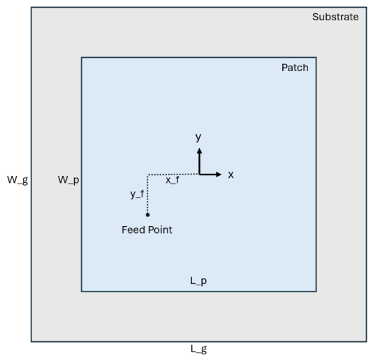
For probe-fed patch antenna design, antenna top view and critical dimensions in this design are given in Figure 2. In a nearly square microstrip patch antenna, circular polarization is achieved by exciting two orthogonal resonant modes with equal amplitude and a 90-degree phase difference. This condition is typically realized by slightly perturbing the symmetry of the square patch—such as by truncating opposite corners, introducing slots, or offsetting the feed position—which splits the degenerate modes and enables them to radiate simultaneously.
Substrate borders are also the borders of ground-plane of the antenna. During all of the design phases in this work, ground plane dimensions are related with patch dimensions with the amplification factor of 1.5. A linearly polarized square patch antenna is designed by taking the transmission line (TL) method into account as outlined in [9]. In this approach, the practical width is first calculated to determine the effective dielectric constant e f f and the extended length (ΔL) caused by the fringing effect. The antenna length (L) is then calculated by using Equation (1), based on the center frequency (fc) and the speed of light (c).
L = c 2 f c e f f 2 Δ L
As a first design step of a linearly polarized antenna, e f f is chosen to be equal to Ꜫr (dielectric constant), which is the standard dielectric constant of the chosen substrate material. After initial calculation, the real e f f value is calculated by using Equation (2) as given in [9] in which h represents the height of substrate.
e f f = r + 1 2 + r 1 2 [ 1 + 12 h L ] 1 2
By determining the substrate material and the height of the substrate, the initial parameters of a linearly polarized patch antenna are calculated and the antenna can be designed through any full-wave electromagnetic solver antenna design software package (e.g., CST, FEKO, HFSS). For that antenna, impedance bandwidth is related to the quality factor Q and VSWR (Voltage Standing Wave Ratio) by using Equation (3).
B W L P I m p = V S W R m a x 1 Q V S W R m a x
The Q factor of the antenna is determined by examining the simulation results of linearly polarized antenna accordingly. The width (W) and length (L) of the nearly square patch antenna are related to the quality factor by Equation (4) [10,11].
W L = 2 Q + 1 2 Q 1
These equations provide the initial design parameters to get nearly square patch antenna. In each step, there may be additional effort to tune the antenna at the center frequency and get axial ratio below 3 dB at the desired frequency band. This requirement can be achieved by using optimization tools or parameter sweep properties of antenna design tools or using analogy between the dimensions and frequency of the patch antennas.

2.2. Unit Antenna Element Design, Simulation and Measurement

For the unit antenna element design, Rogers RO3006 (Rogers Corporation, Chandler, AZ, USA) was selected as the substrate material. This material was considered advantageous due to its relatively high dielectric constant, which enables more compact antenna dimensions. The basic reason for this relation comes from Equation (1) which inversely relates L of the patch antenna with dielectric constant of the substrate material.
Initially, a square shape design architecture was adopted, and a linearly polarized antenna design procedure was followed. For the final optimized design for the linearly polarized antenna, the length and width of the patch are the same and 36.41 mm. x_f and y_f values are again the same and are equal to 3.5 mm.
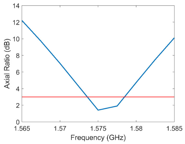
Following the design of the linearly polarized (LP) unit element, the development of a right-hand circularly polarized (RHCP) unit element was initiated. The final design parameters of the proposed antenna are L_p = 36.43 mm, W_p = 36.87 mm, x_f = 3.5 mm and y_f = 5.5 mm. The performance results for optimized single element are: 21.87 MHz bandwidth considering S11 under −10 dB (VSWR: ~2), 4.79 MHz bandwidth considering 3 dB axial ratio (AR), 1.575 GHz center frequency, 1.3 dB axial ratio at 1.575 GHz and 2.7 dBi realized gain at antenna boresight for the center frequency. The pattern result of the single element is like a half hemisphere shape, and this result is remarkably satisfactory for the coverage expectations.
Axial ratio results in the simulation for the designed single antenna are given in Figure 3. Expected axial ratio value is below 3 dB (Red Line) for circularly polarized antennas, and the result around 1.575 GHz (Blue Line) indicates a sufficient value for the designed single element.
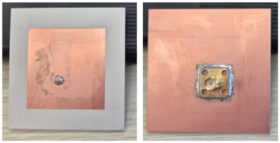
Upon confirming that the simulation results of the proposed design met the target performance criteria, the antenna was manufactured. The top and bottom views of the manufactured single-element antenna are shown in Figure 4.
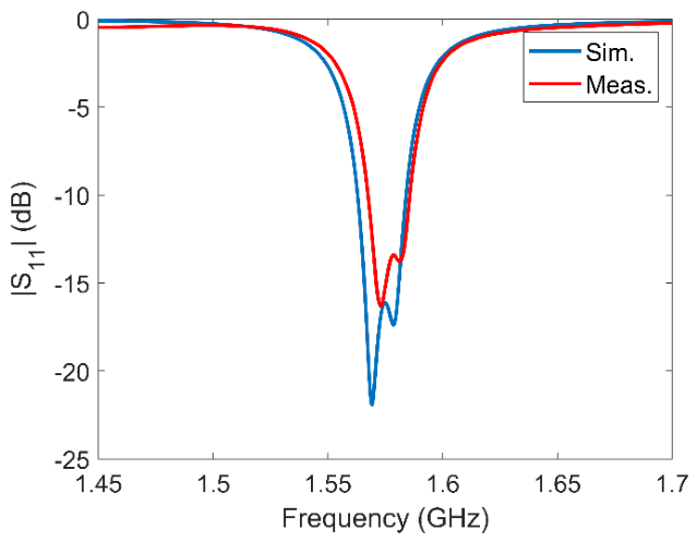
Following manufacturing, the impedance matching of the antenna was verified by measuring S11 parameters at the feed port by using a network analyzer. A comparison between the measured and simulated S11 parameters is provided in Figure 5. According to the simulation and measurement results, the bandwidth values corresponding to the frequency range where the S11 remains below −10 dB are highly similar and the center frequency of the antenna is 1.5765 GHz for the fabricated antenna, whereas the center frequency of the simulated antenna is 1.5750 GHz. The frequency shift between simulated and manufactured antenna is 1.5 MHz which is around 0.1%.
The strong correlation between the measurement and simulation results for such a highly resonant antenna indicates the accuracy in the manufacturing processes and the consistency of the substrate’s dielectric constant with its catalog specifications. The obtained results also serve as a practical validation of the theoretical foundation underlying the design and, consequently, of the design itself, thereby adding further significance to the study. This outcome has provided motivation to proceed directly to array design without the need for any revisions to the single-element antenna.

3. Reference Antenna Array Design

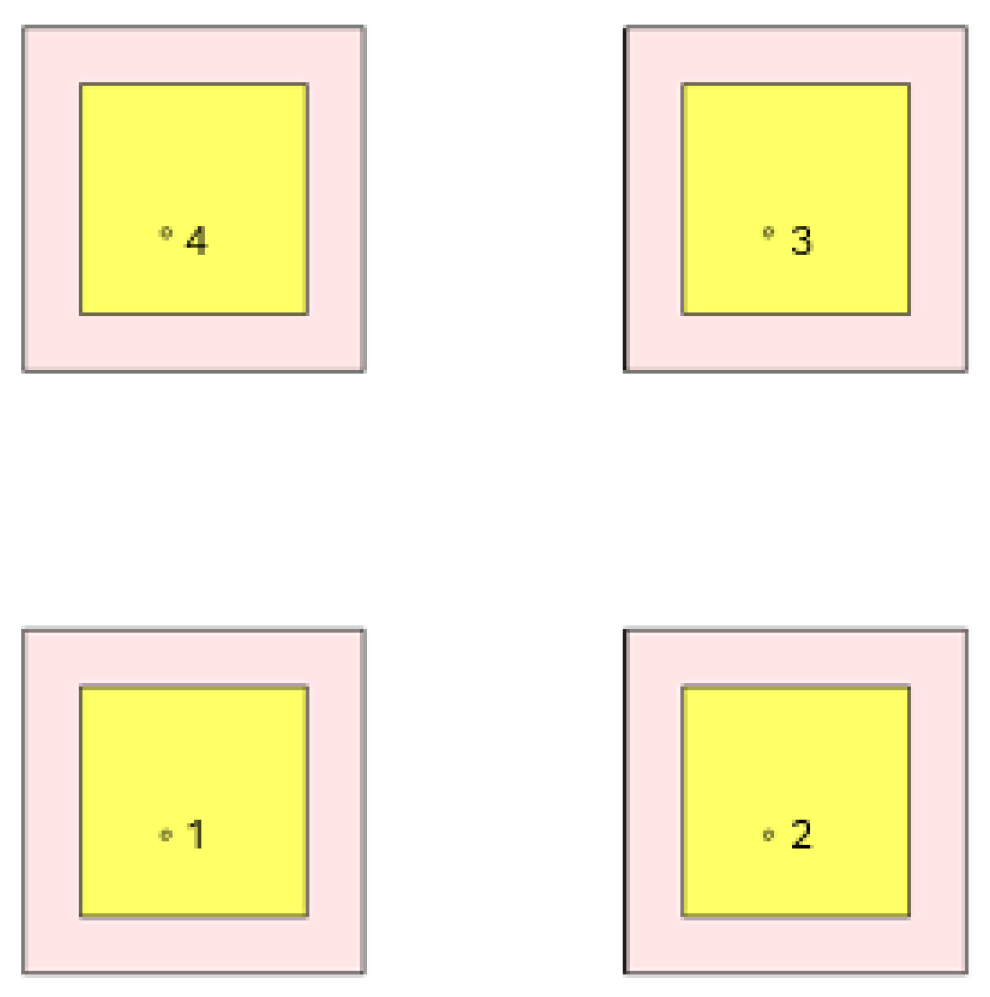
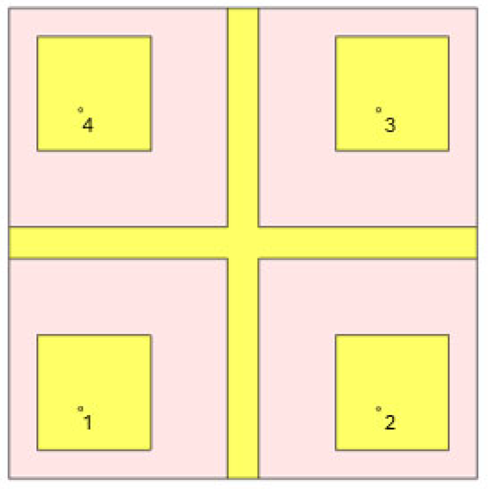
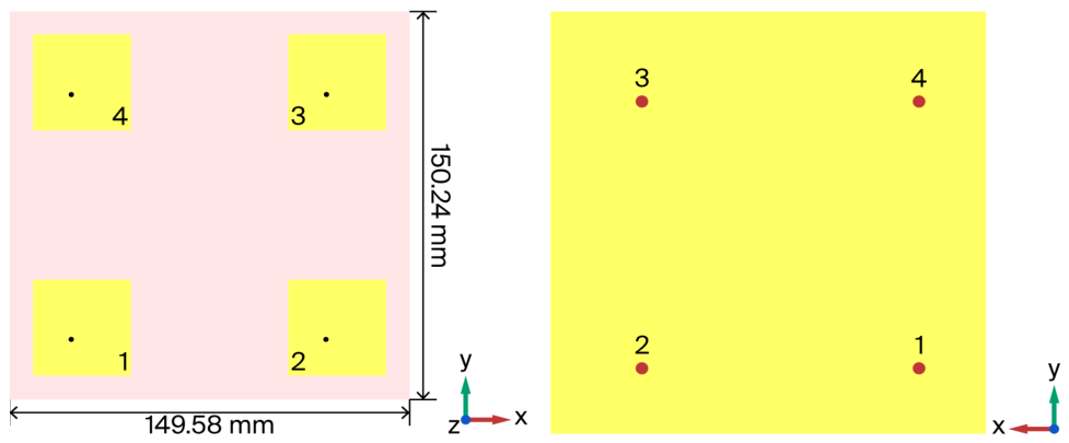
Within the scope of this study, a reference antenna array design was proposed to evaluate the effectiveness of antenna miniaturization and coupling-reduction techniques. For this purpose, a four-element antenna array with half-wavelength spacing was selected. The array architecture adopted in this work was based on the design presented in [12]. However, due to the use of different substrate material (Rogers RO3006 instead of RO4003), it was necessary to redesign the reference array accordingly. The antenna dimensions were revised as part of the array design process. Since transitioning from a single antenna to an array structure may lead to performance variations due to mutual coupling effects, the original dimensions could not be used directly. Initially, the design was based on the parameters of the single-element antenna, and optimization was carried out with respect to the length, width, and feed point location. The final design is presented in Figure 6 as a top and bottom view. In the design, the yellow-colored regions represent the conductive parts, while the other color shown in the top view represents the substrate material. For this reference array, the outer dimensions are around 15 cm. The length and width of the unit element within the array are 36.22 mm and 36.66 mm. All elements have identical designs in patch dimensions and feed points.
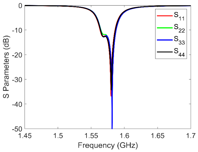
One of the critical parameters for the reference antenna array is the S-parameters. These parameters provide insight into the impedance matching of the individual antenna elements and the level of mutual coupling between elements. Impedance matching simulation results are given in Figure 7. These results show that all antenna elements cover the target frequency range within the –10 dB bandwidth and have good impedance matching.
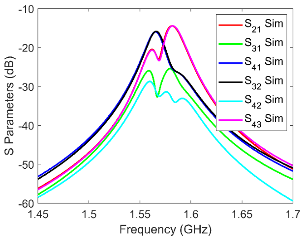
Isolation between antenna elements of the reference CRPA is given in Figure 8. According to the simulation results, the worst isolation level between antennas is around 14.4 dB. This level is accepted as the reference level while miniaturizing the CRPA and applying decoupling solutions. The observed non-symmetry in the coupling coefficients is mainly caused by non-uniform current distributions and near-field interactions between the antennas, which are affected by small geometrical and structural variations.
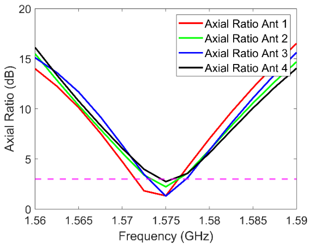
The axial ratios of the antenna elements are given in Figure 9. The axial ratio is less than 3 dB at the center frequency for all of the antenna elements, and circular polarization is achieved successfully. The axial ratio results demonstrate that circular polarization performance varies slightly among the antennas due to differences in modal excitation and mutual coupling effects.
Since the target performance goals in terms of impedance matching and polarization were achieved at the desired center frequency in the implemented design, this reference antenna array design was finalized for manufacturing.

4. Antenna Array and Miniaturization

The most fundamental approach to miniaturize an antenna array is to reduce the inter-element spacing. However, if this procedure is done without taking any precautions, the mutual coupling between antenna elements increases, which in turn causes performance degradation. Within the scope of this study, the objective was to reduce the inter-element spacing to 0.3 λ, while simultaneously implementing additional measures to mitigate coupling. The ultimate goal is to identify the most effective method and design an antenna array that achieves isolation levels comparable to those of a reference array with half-wavelength spacing. A review of the literature reveals that only a limited number of studies have focused on achieving miniaturized dimensions in CRPA designs. Moreover, a few of these studies addressed coupling mitigation following miniaturization. Furthermore, it has been observed that most of the studies employ a single technique, without performing comparative analysis against a reference antenna array design.

4.1. Literature Survey

A study run by James G. Maloney et al. focused on the design of a miniaturized GPS CRPA [13]. The work highlighted the effectiveness of CRPA in mitigating GNSS jamming and aimed to reduce the antenna size for use on space-constrained platforms. The design employed fragmented aperture patch elements and targeted operation in the L1 and L2 bands without performance loss. While the simulation and measurement results were reported to be consistent, the study did not address some aspects such as polarization, inter-element isolation, or comparison with a full-sized reference design.
In the study by Zhou et al. [4], a compact CRPA was designed by using 25 mm-diameter antenna elements with slotted patch structures to avoid bandwidth reduction. A dual-band response was achieved through a multilayer design, and a 4-element array was implemented. Although significant miniaturization was achieved (with λ/6 spacing), no measures were taken to reduce coupling, leading to reduced array performance.
Guo et al. [14] proposed an 8-element miniaturized GPS CRPA using high-permittivity material and U-slot patches to reduce element size. The design achieved 20 MHz 10 dB bandwidth, good axial ratio, and RHCP across all elements. Although the array met key performance targets, the axial ratio slightly degraded due to a lack of element-level tuning, and S21 analysis was not provided to assess coupling effects.
In Caizzone’s study [7], a compact CRPA operating in the Galileo E5a and E1 bands was designed with dimensions of 10 cm × 10 cm. A metallic wall was placed between elements to reduce coupling, and the performance was evaluated through cross S-parameters. A dual-feed, multilayer patch structure on a high-permittivity RO6010 substrate was used for dual-band operation. The results show that the metallic wall substantially improves isolation; however, axial ratio performance was not reported, and full assessment of polarization characteristics was limited.
Xuan Shao et al. [8] discussed the increasing use of multiband GNSS antennas to mitigate intentional and unintentional interference. The study addressed the challenge of increased coupling caused by reduced inter-element spacing in compact CRPAs by applying ground-plane modifications to preserve antenna radiation characteristics, particularly axial ratio. A four-element, multilayer patch CRPA was designed and fabricated, featuring probe-fed and coupled-fed elements. Ground-plane slots were introduced between elements, resulting in improved axial ratio and up to 4 dB isolation enhancement across L1, L2, and L5 bands. Although coupling reduction improved performance, compactness gains were limited. The study noted that coupling-induced pattern distortion might degrade jamming suppression but did not provide detailed pattern or suppression analysis.
Xiaojian Wang et al. [3] studied the effects of mutual coupling on GNSS antenna arrays, highlighting its negative impact on jammer suppression performance, including reduced signal-to-interference-plus-noise ratio (SINR) and degraded null steering. By using a 4-element compact CRPA design and element pattern analysis via HFSS simulations, they compared scenarios with and without absorber walls between elements. Results showed that coupling reduction deepened null depths, improving interference rejection. However, the study lacked data on fundamental antenna parameters before and after coupling reduction and did not assess equivalence to a larger array, which limited evaluation of miniaturization benefits.
Hehenberger et al. [15] presents a miniaturized wideband GNSS array based on dielectric resonator antennas. The proposed design achieves a mutual coupling level of approximately −15 dB at an inter-element spacing of about 0.2 λ, with a primary focus on wideband operation and platform integration.
A. Madni and W. T. Khan [16] studied a compact 4-element GNSS array employing a hybrid decoupling approach based on a defected ground structure (DGS) and a microwave absorber, achieving isolation levels exceeding 25 dB across the operating band. The improved isolation performance is achieved through the incorporation of additional materials and design elements, resulting in increased structural complexity.
Abdullah Madni et al. [17] demonstrates a high-efficiency GNSS antenna array with strong mutual coupling suppression (above 24 dB) achieved through the combined use of a defected ground structure (DGS) and a meta-isolator. However, the design primarily relies on a relatively thick and high-permittivity substrate (εr ≈ 10.2, h = 5.08 mm), which inherently increases the profile and limits its applicability for low-profile or platform-constrained CRPA systems. In contrast, the proposed work focuses on achieving comparable or improved isolation performance under considerably reduced inter-element spacing and lower-profile constraints, which are more representative of practical CRPA implementations.
Metasurface-assisted decoupling approaches have also been reported in the literature for compact CP antenna arrays. In [18], a double-sided decoupling metasurface (DSDM) was utilized to improve isolation through polarization conversion and evanescent-wave suppression mechanisms. Unlike such superstrate-based approaches, the proposed study achieves coupling reduction directly within the CRPA structure by combining multiple physically integrated isolation techniques.
Recent studies have also explored non-uniform array topologies to improve electromagnetic performance through optimized element spacing and aperture shaping. In [19], a non-uniform Van Atta array was developed to enhance broadband retrodirective and RCS performance. In contrast, the proposed study focuses on coupling suppression within a compact CRPA architecture without increasing the inter-element spacing.
It is evident that studies in the literature specifically addressing both miniaturization and mutual coupling reduction in CRPA systems are relatively limited. On the other hand, mutual coupling has been widely recognized as a critical issue in antenna arrays designed for various frequency bands, particularly as the inter-element spacing is reduced to achieve compact configurations. This interaction leads to degradation in key performance metrics such as impedance matching, radiation pattern stability, and array efficiency. Consequently, numerous studies have focused either on mitigating coupling effects through dedicated decoupling techniques or on incorporating coupling into the design process and optimizing the overall system performance despite its presence. However, achieving a balanced trade-off between array miniaturization and effective coupling suppression remains a demanding problem, especially for CRPA applications where strict isolation and pattern control requirements are imposed by anti-jamming functionalities.
Xiao Cai et al. [20] proposed a compact linear microstrip array which is designed using the EMMPTE (Extended Method of Maximum Power Transmission Efficiency) method, where the inter-element spacing is reduced from 0.5 λ to 0.35 λ, achieving a 28.2% size reduction while accounting for mutual coupling effects. The proposed approach enables accurate pattern synthesis with a deviation below 0.9 dB and sidelobe levels under −20 dB, demonstrating effective miniaturization without significant performance degradation.
The decoupling cavity (DC) approach proposed by Shengyuan Luo et al. [21] demonstrates an isolation enhancement of approximately 24 dB in half-wavelength (~0.5 λ) spaced MIMO arrays by effectively suppressing space–wave coupling. However, the effectiveness of this approach largely relies on relatively wide inter-element spacing and the incorporation of an additional volumetric superstrate structure. This characteristic limits its direct applicability to miniaturized and low-profile array configurations, such as CRPA systems. Furthermore, since the proposed method primarily targets space–wave coupling, its performance may be inferior in effectiveness in compact arrays where surface–wave and near-field coupling mechanisms are more dominant.
Heming Wang et al. [22] proposes a metamaterial-based decoupling wall that improves both isolation and bandwidth in a dual-band MIMO antenna. While notable gains are achieved, the study is limited to a two-element configuration and does not address key CRPA requirements such as multi-element array behavior and adaptive beamforming. In addition, the introduced structure causes radiation pattern distortion and increases the profile, which may degrade array performance and limit its applicability to compact GNSS CRPA systems.
The study performed by Navdeep Singh et al. [23] demonstrates a material-based isolation improvement of 7.7 dB using a BaFe12O19 slab between separated Tx/Rx arrays However, the approach relies on physical separation and bulky structures, making it unsuitable for compact CRPA systems with closely spaced elements. Therefore, its direct applicability to CRPA architectures is limited, particularly in miniaturized and platform-integrated scenarios.
Ling-Xuan Lin et al. [24] proposes an array decoupling surface (ADS) to considerably enhance isolation in a compact millimeter-wave MIMO array with closely spaced antenna elements (0.329 λ0), achieving isolation improvements. The approach is particularly noteworthy for maintaining radiation characteristics while enabling a highly compact array configuration, which is a critical requirement for CRPA systems with limited aperture size.
In the literature, various array antenna miniaturization and coupling-reduction techniques have been reported, including parasitic elements, defected ground structures (DGS), neutralization lines, metasurfaces, orthogonal element placement, and polarization diversity methods [25,26,27,28,29]. Several studies have demonstrated effective isolation enhancement through parasitic structures and slot-based decoupling approaches, particularly for compact MIMO configurations [25,27]. Other works have focused on orthogonal element arrangements, polarization diversity, metasurface loading, or neutralization-line techniques to improve isolation performance in compact array environments [26,28,29]. However, unlike many of these studies, which generally focus on a single dominant decoupling mechanism or conventional MIMO array configurations, the present work specifically addresses the miniaturization of a compact GNSS CRPA architecture operating under severe inter-element spacing constraints. In this context, the proposed study distinguishes itself through the combined and constraint-oriented implementation of multiple hybrid coupling-reduction techniques together with a direct comparison against a reference CRPA configuration.

4.2. Miniature CRPA Design and Applied Coupling-Reduction Methods

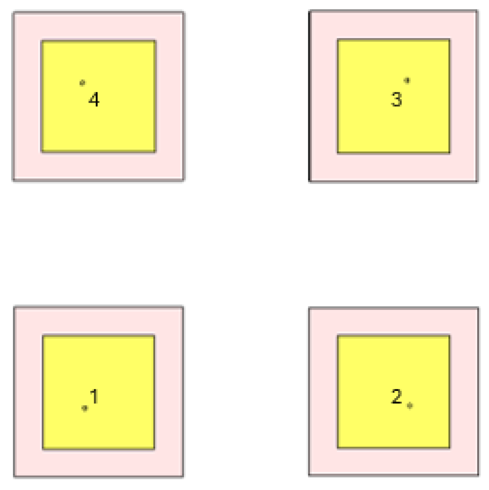
The first step in the CRPA miniaturization process involved reducing the inter-element spacing in the reference CRPA design from half a wavelength to 0.3 λ and observing the resulting performance metrics. The simulated results for antenna impedance matching and isolation under this configuration are presented in Figure 10 and Figure 11. The simulation results indicate that increased mutual coupling between elements (Isolation up to 10 dB) led to discernable changes in antenna characteristics, including degraded impedance matching.
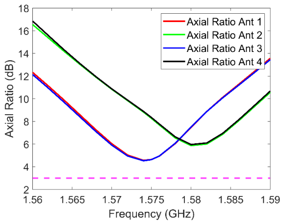
Axial ratio results for the antenna elements within the array are given in Figure 12. An axial ratio exceeding 3 dB indicates a partial loss of RHCP behavior if there are no precautions and decoupling methods while only miniaturizing the array.
Based on the results of this initial study, the requirement for an additional measure was recognized, prompting the search for a design that would minimize inter-element coupling while providing an optimal solution for the integration into an airborne platform. The methods explored throughout these efforts can be summarized as given in the following subsections.

4.2.1. Separate Ground (Gnd) and Substrate (Method 1)

This method eliminates potential physical points of convergence that could lead to mutual coupling between the antennas and ensures that the antennas are kept completely independent.

4.2.2. Separate Substrate and Common Gnd (Method 2)

This method is a design approach in which the substrate layer—identified as a potential source of coupling—is partially removed in a defined region, and a common ground plane is utilized.

4.2.3. EBG Separation (Method 3)

Mushroom-type EBG structure is considered in design to suppress coupling by using the theory given in [30,31].

4.2.4. Separate Gnd and Common Substrate (Method 4)

This method is a design approach in which the ground layer, identified as a potential source of coupling, is partially removed in a defined region, and a common ground plane is utilized.

4.2.5. Separate Gnd and Substrate with Metallic Wall (Method 5)

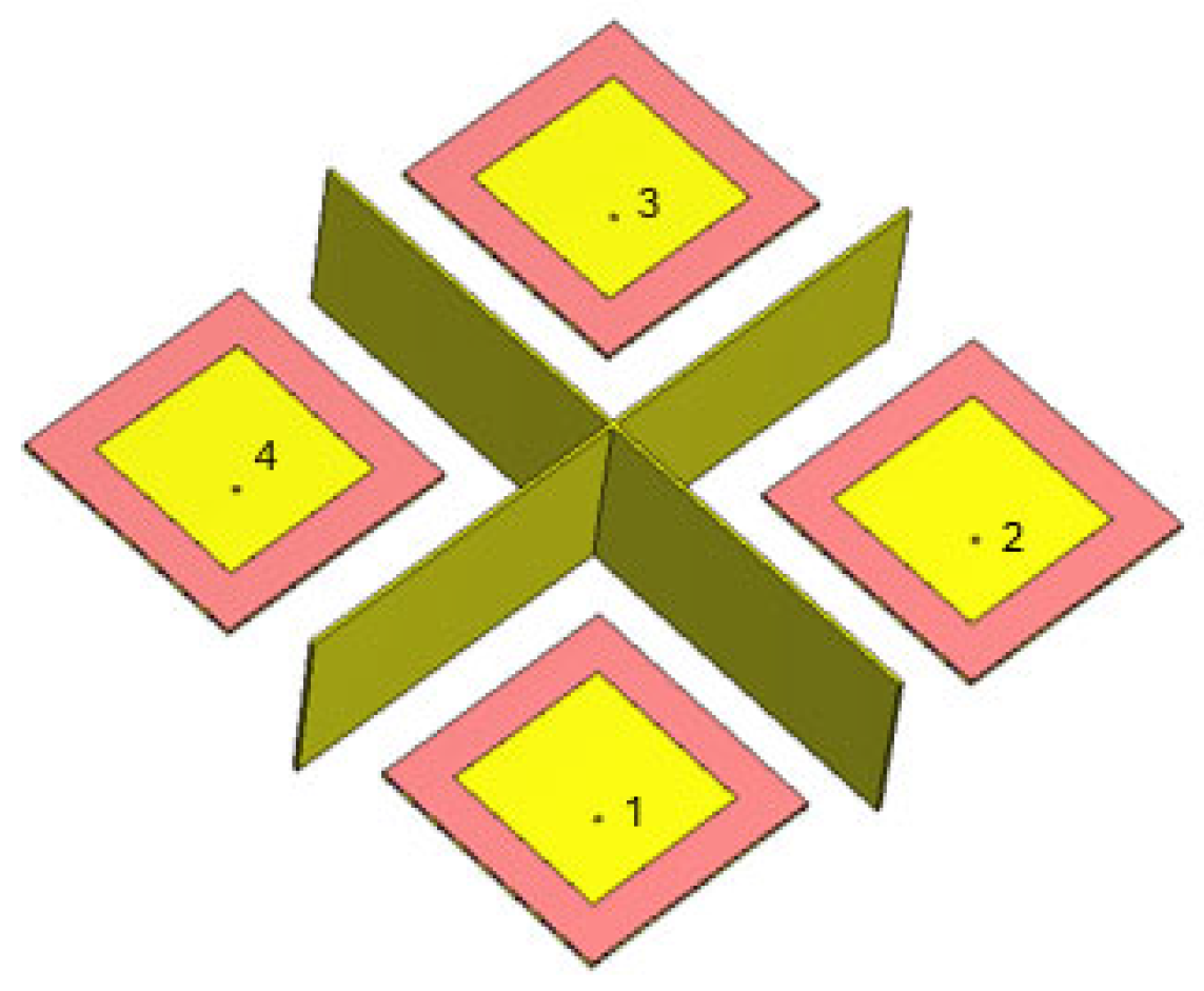
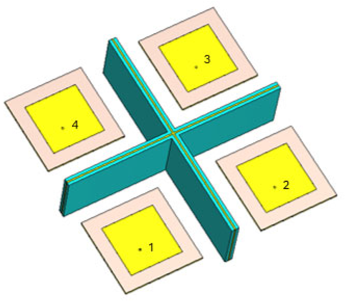
In this method, a design was implemented to physically eliminate the coupling between antennas and to suppress mutual coupling through the air. In this context, a metallic wall was introduced between the antennas.

4.2.6. Separate Gnd and Substrate with Rotated Antenna Elements (Method 6)

In this design, adjacent antennas were rotated by 90 degrees to maintain the spacing between antennas while increasing the distance between their feeding points with the objective of enhancing.

4.2.7. Separate Gnd and Substrate with Absorber Wall (Method 7)

M. Awais et al. [32] presented the use of an absorber to improve isolation. In the present work, unlike the referenced study, the absorber material was placed between the antennas in a perpendicular shape.
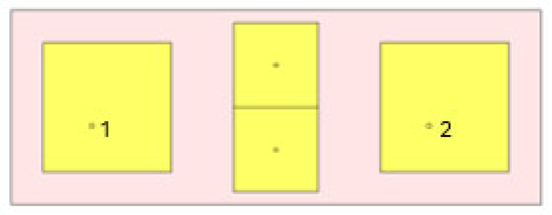
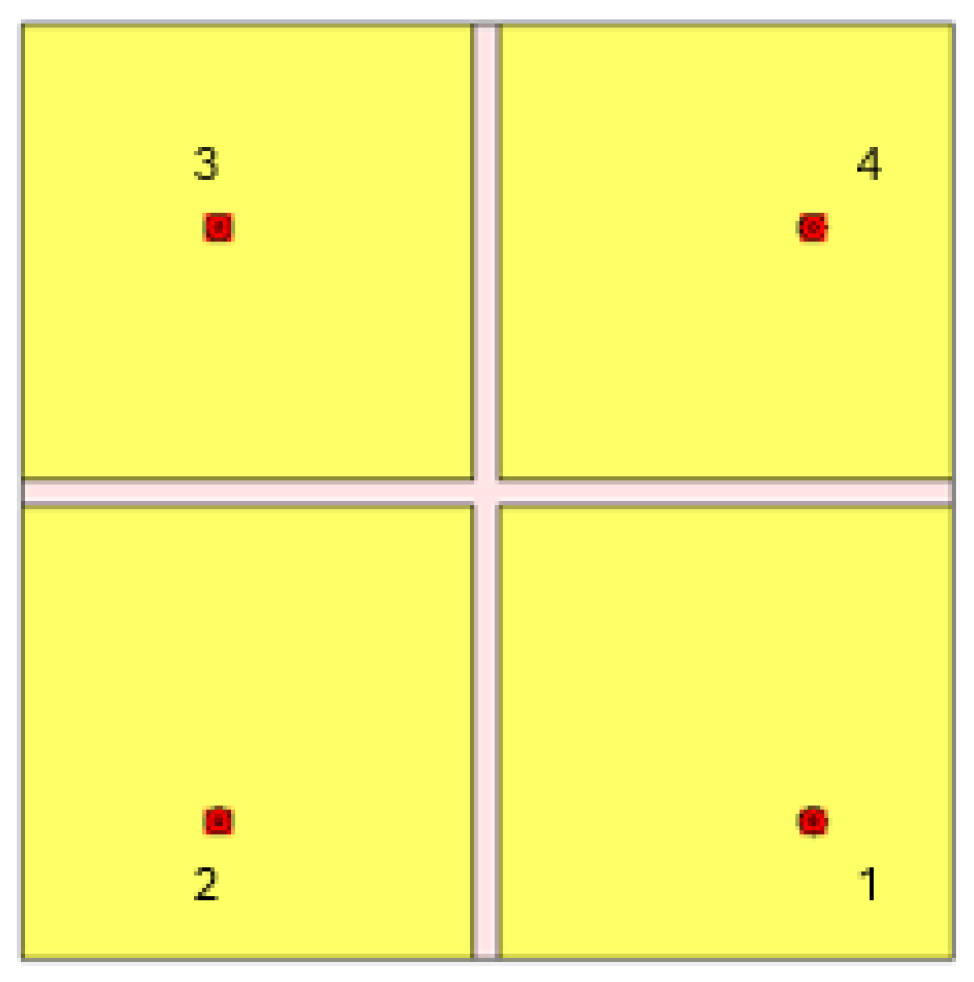
Throughout the implementation of these methods, the inter-element spacing was consistently maintained at half a wavelength. The approach considered to be the most effective was selected for further development, with the aim of achieving an optimized and miniaturized CRPA design. Visual representations of the implemented designs are provided in Figure 13, Figure 14, Figure 15, Figure 16, Figure 17, Figure 18 and Figure 19. The numbering shown in the antenna figures is provided as a virtual annotation solely for clarification of the antenna numbering scheme.
The isolation levels observed between the antennas in the corresponding studies and their comparison with those of the reference antenna array, to which no coupling reduction method was applied, are presented in Table 1.
In CRPA designs, four-element antenna arrays are commonly employed due to their ability to provide sufficient spatial degrees of freedom for adaptive beamforming and interference suppression. However, when evaluating mutual coupling performance, the most critical metric is typically associated with the antenna pair exhibiting the highest level of coupling within the array. Accordingly, the table has been constructed based on the isolation results of the antenna pair experiencing the strongest mutual interaction. This approach provides a conservative and representative evaluation of the array’s coupling characteristics, as the worst-case isolation effectively determines the overall mutual coupling performance of the CRPA structure. By focusing on the most strongly coupled antenna pair, the presented results highlight the limiting case that governs array performance and ensures a meaningful comparison among the design methods investigated.
Based on the obtained results, it can be asserted that reducing the use of a common ground plane between antennas, increasing the distance between feed points by rotating the antennas, and minimizing the physical connections between antennas are effective and significant methods for improving coupling reduction. The outcomes achieved by each applied method are provided in Table 1. The results addressing mutual coupling among all antennas within the CRPA are also presented in Table 2, and the comprehensive results provided therein further support the conclusions drawn from Table 1.
In Method 1, complete separation of antennas, including ground and substrate, yields notably better results than the reference CRPA design by increasing isolation from 14.7 dB to 20.8 dB. Eliminating the common interfaces both on the ground plane and at the substrate level substantially suppresses any potential interference that may originate from these surfaces. Among the applied decoupling approaches, this method demonstrated one of the most pronounced contributions to the achieved isolation enhancement. However, separation of antennas is not a good option considering the combined CRPA product for aircrafts.
In Method 2, the common substrate plate has been identified as one of the potential sources of inter-antenna interference, and its influence has therefore been investigated. Separation of substrate is not an effective option when the results are compared with reference CRPA considering similar isolation results around 14.6 dB. While substrate separation is generally expected to contribute to coupling mitigation, the present results indicate that the shared substrate does not appear to be the dominant coupling path in the proposed configuration.
In Method 3, by means of the structure designed by using the EBG technique between the two antennas, it is intended to suppress the interference that may arise from surface waves. Nevertheless, design work with EBG application was applied to a two-element design for testing of effectivity. Application of EBG results in nearly 1.3 dB isolation improvement, which is not an apparent value. The given isolation value is not comparable with other results because the value is given from a two-element design.
The implementation of Method 4 is intended to examine the impact of the interference that may be induced through the common ground plane in inter-antenna coupling. In Method 4, design approach with separate ground and common substrate brings clear improvement from 14.7 dB to 17.2 dB in isolation between antenna elements. The combined assessment of Method 1, Method 4, and the reference CRPA results suggests that the applied ground-plane separation plays a significant role in suppressing one of the dominant inter-element coupling paths.
In Method 5, the objective is to observe the effect of over-the-air interaction on the inter-antenna isolation by application of metallic wall. According to the results, there is some improvement from 20.8 dB to 22.6 dB in isolation considering the CRPA in Method 1, but the value is not apparent. Moreover, the utilization of metallic walls in a unified antenna structure was not regarded as an optimal implementation approach in terms of structural integration. Such structures were also considered likely to adversely affect the radiation behavior and pattern stability of the individual unit elements.
In Method 6, there is significant improvement in isolation. The results indicate that increasing the distance between the feed points plays a significant role in improving the inter-antenna isolation. While maintaining the same antenna placement configuration as Method 1, this approach introduces a sequential 90-degree rotation between adjacent antenna elements. This modification increased the achieved isolation level from 20.8 dB to 28.6 dB, revealing a significant reduction in inter-element coupling effects.
In Method 7, 1.8 dB improvement according to CRPA in Method 1 exists but the value is not apparent. It can be noted that the absorber plate added onto the standard metallic wall does not provide a significant benefit in mitigating the inter-antenna interference and fails to suppress the principal components of the over-the-air coupling.
In this work, a compact CRPA structure with an inter-element spacing of 0.3 λ has been developed while preserving a unified (monolithic) architectural structure, which is a critical requirement for practical system integration. Achieving sufficient isolation under such aggressive miniaturization constraints is particularly challenging due to the strong mutual coupling between closely spaced antenna elements.
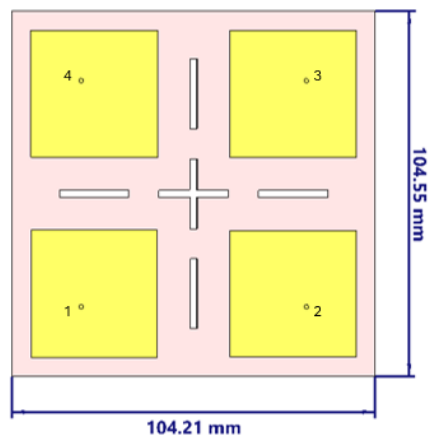
To address this challenge, the proposed design adopts a hybrid isolation mitigation strategy, in which multiple complementary design mechanisms are jointly exploited. Specifically, the ultimate CRPA configuration incorporates: (i) a unified structural architecture to satisfy integration requirements, (ii) rotated antenna elements to effectively increase the separation between phase centers, (iii) slot structures introduced between antenna elements to suppress surface current coupling, and (iv) partial ground separation to further reduce inter-element interference.
While each of these techniques has been investigated individually in the literature, the main contribution of this work lies in the systematic hybrid integration of these mechanisms within a highly miniaturized CRPA platform. In particular, the final antenna architecture uniquely combines the most effective insights obtained from Method 2, Method 4, and Method 6, enabling a balanced trade-off between compactness, structural integrity, and isolation performance. This hybrid design approach allows the proposed CRPA to maintain acceptable inter-element isolation despite the severe spatial constraints imposed by the 0.3 λ antenna spacing.
In the proposed miniature CRPA design, a unitary and mechanically integrated structure is preserved to maintain structural robustness and platform compatibility. However, since reduced inter-element spacing significantly increases mutual coupling, multiple complementary isolation techniques are jointly employed.
First, adjacent antenna elements are sequentially rotated by 90° to reduce electromagnetic field overlap between neighboring feed and radiating regions. This arrangement reduces near-field electromagnetic interaction and weakens direct coupling between adjacent elements.
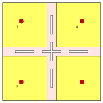
Second, slots are introduced between adjacent substrate regions to suppress substrate-mediated surface–wave propagation. These slots disturb the continuity of electromagnetic surface–wave modes within the substrate and reduce coupling through the substrate, which becomes increasingly dominant in compact arrays with spacings below 0.5 λ.
Finally, the electrical connection between neighboring ground planes is eliminated. Since common-ground current propagation can represent one of the dominant coupling mechanisms in compact microstrip arrays, isolating the ground regions effectively suppresses surface-current transfer between adjacent elements and improves inter-element isolation.
By combining element rotation, substrate slotting, and ground-plane isolation within the same design, the proposed approach simultaneously mitigates multiple dominant coupling mechanisms and enables substantial CRPA miniaturization while demonstrating substantially improved isolation performance compared to a 0.5-wavelength-spaced reference CRPA.
The proposed design distinguishes itself by achieving substantial CRPA miniaturization while preserving structural integrity and simultaneously enhancing inter-element isolation through a hybrid multi-technique coupling-reduction approach without significantly degrading impedance matching and radiation characteristics.
It should be noted that the primary focus of this study is the investigation and mitigation of inter-element coupling in a compact CRPA structure. Therefore, the radiation pattern analysis presented in this work is based on full-wave electromagnetic simulations performed during the design stage.

4.3. Final and Optimum Miniaturized CRPA Design

As stated in the previous section, based on the data obtained from all conducted studies, a set of hybrid methods was employed following the CRPA miniaturization process, aiming at achieving a design comparable to the reference CRPA. After initial design with previous single element dimensions and feed points, design is optimized to have good impedance matching at 1575 ± 10 MHz and good axial ratio below 3 dB at 1575 MHz by changing some parameters and dimensions (Length, Width, Feed point in x axis and y axis). The final design parameters for the elements of the proposed miniature CRPA are L_p = 36.2038 mm, W_p = 36.4586 mm, x_f = 3.75 mm and y_f = 3.5 mm. Outer dimension borders are 104.21 mm × 104.55 mm and the total surface area is reduced 52% considering reference CRPA design with half-wavelength spacing. Top and bottom views of the fully original miniature CRPA design are given in Figure 20 and Figure 21.
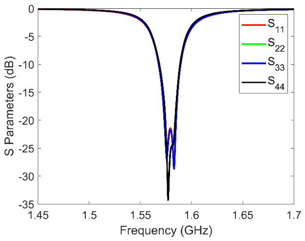
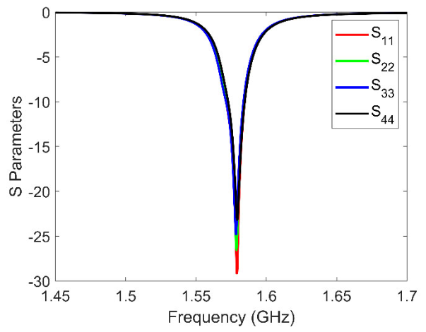
Impedance matching simulation results for the designed miniature CRPA is provided in Figure 22. As one can observe, the target center frequency is within the −10 dB bandwidth, although 20 MHz bandwidth is not provided. This level of bandwidth was the optimum result in this design architecture by using the material and could not be improved while protecting axial ratio below 3 dB. Aiming at reducing the quality factor by employing a substrate with a lower dielectric constant and increased thickness can increase the bandwidth by enhancing fringing fields, thereby improving the impedance bandwidth, without altering the fundamental patch geometry. Through the steps, the antenna bandwidth can be extended, providing improved coverage for GNSS-related applications. Nevertheless, in this study, to realize and practically implement the antenna design, a commercially available substrate material was selected due to material availability and cost constraints faced by the designers. Considering inter-element isolation levels, this design architecture brings almost the same isolation level with reference CRPA with 0.5 λ separation. This result was the primary advantage of this design, and the main goal considering isolation values is achieved, although antennas are separated by an extremely small distance.
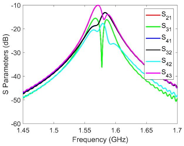
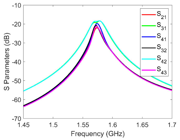
Isolation between antenna elements of miniature CRPA is given in Figure 23. Although the inter-element spacing was reduced from 0.5 λ to 0.3 λ, the inter-element isolation, which was simulated as 14.4 dB in the reference CRPA, was improved to 18.5 dB in the newly designed miniature CRPA. This result clearly demonstrates the high effectiveness and efficiency of the implemented coupling-reduction techniques. In fact, this improvement should not merely be interpreted as an approximately 4 dB enhancement relative to the reference CRPA. Rather, it should be evaluated considering that, for a CRPA with a similar inter-element spacing but without any coupling-reduction measures, the inter-element isolation would typically degrade to around 10 dB, whereas the proposed design successfully achieves isolation levels exceeding 18.5 dB. When assessed from this perspective, the effectiveness and significance of the proposed approach become substantially more evident.
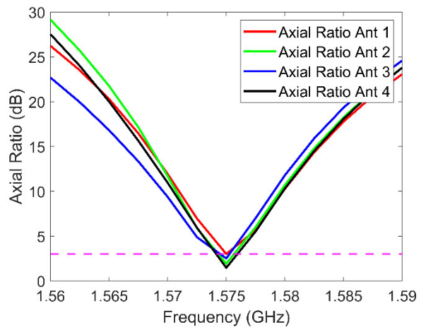
Simulation results for the axial ratio are given in Figure 24. According to the simulation results, an axial ratio below 3 dB was achieved for all the antenna elements with limited bandwidth. These results demonstrate that circular polarization is achieved again, although antennas are much closer to each other and decoupling methods are successful.
One of the key parameters in evaluating the isolation between antenna elements is the surface current distribution induced on neighboring elements when a particular antenna is excited. In tightly spaced antenna arrays such as CRPAs, mutual coupling is not only reflected in the S-parameters but also manifests through induced surface currents on adjacent radiating elements. Therefore, examining the surface current density provides valuable insight into the underlying coupling mechanisms within the array.
In this study, to further investigate the interaction between antenna elements, each antenna in both the reference CRPA and the optimized CRPA was excited individually while monitoring the resulting surface current distributions on the remaining elements. This approach allows a direct visualization of the electromagnetic interaction paths between array elements.
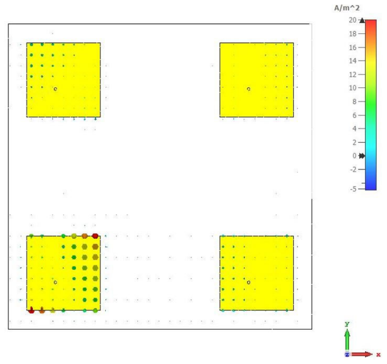
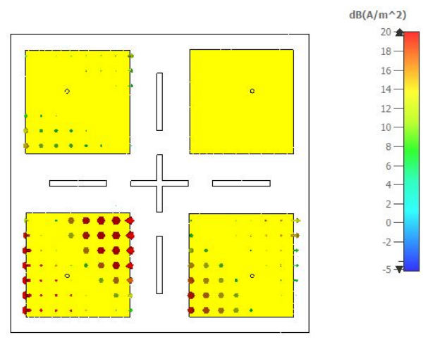
The simulated surface current distributions obtained for a representative antenna excitation in the reference CRPA and the final optimized CRPA are illustrated in Figure 25 and Figure 26, respectively. The results demonstrate that, despite achieving more than a 50% reduction in the overall array footprint, the optimized CRPA design exhibits reduced induced current levels on neighboring elements compared to the reference CRPA. This observation confirms that the proposed design not only enables significant miniaturization but also effectively mitigates inter-element electromagnetic interaction, hence contributing to improved isolation performance within the array.
The operational bandwidth requirement of the antenna is determined based on the characteristics of the GPS L1 signal, which occupies approximately ±10 MHz around the center frequency of 1575.42 MHz. Therefore, the antenna is designed to provide an impedance bandwidth that fully covers this frequency range. In addition, since GPS signals employ RHCP, maintaining an axial ratio below 3 dB around the operational band is considered a key design criterion.
By suppressing mutual coupling, the effective steering vectors of the compact CRPA approach the ideal uncoupled array, thereby reducing array-manifold mismatch. This can improve the accuracy and depth of adaptive spatial nulls generated toward interference directions while preserving the desired GNSS look direction. In this study, the primary objective was to achieve enhanced performance with a miniaturized CRPA design while simultaneously reducing the mutual coupling between antenna elements. In addition to the conducted antenna design studies, a jammer suppression scenario specific to this work was also established based on the optimized miniature CRPA configuration.
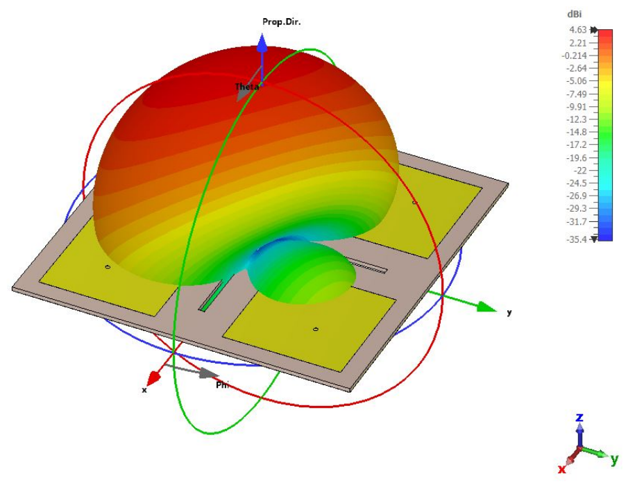
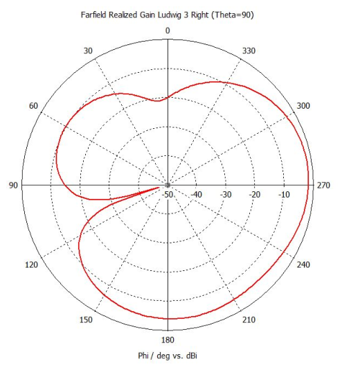
Within this scenario, a MATLAB 2020a (MathWorks, Natick, MA, USA) based code implementing the MVDR (Minimum Variance Distortionless Response) algorithm was developed to calculate the corresponding beamforming weight vectors considering one jammer. Using the defined input parameters, the weight set to be applied to the CRPA was determined as presented in Table 3. Subsequently, this weight set was applied to the optimized miniature CRPA model in CST, and the post-beamforming radiation pattern was obtained through full-wave electromagnetic simulations.
The three-dimensional representation of the obtained results is presented in Figure 27, while the two-dimensional pattern at the θ = 90 cut is provided in Figure 28. According to the results, in the considered single-jammer scenario, near-ideal null depths (up to 50 dB) were successfully achieved within the electromagnetic simulation environment.
Although beamforming and null-steering analyses were not the primary focus of this phase of the study, a representative jammer-suppression scenario was included to provide a preliminary indication of the potential anti-jamming capability of the final CRPA configuration. Nevertheless, comprehensive investigations involving adaptive beamforming, dynamic null steering, and advanced spatial filtering techniques remain beyond the scope of the present work and will be addressed in future studies.
In this design procedure, several optimization studies were carried out and the optimal result was utilized by considering design limitations. Therefore, this design was chosen for manufacturing and measurement. The achieved isolation enhancement is considered to originate from the combined reduction in surface–wave coupling, increased effective current-path separation through element rotation, and suppression of undesired coupling paths enabled by the applied structural modifications.

5. Manufacturing and Measurement Results for CRPA

In this work, after finalizing the design, manufacturing and measurement of the single element, CRPA design options were improved by considering both the reference CRPA and the miniature CRPA. When sufficient and optimum simulation results were obtained, the manufacturing process was applied for reference CRPA and miniature CRPA and the manufactured antennas were measured considering S-parameters. S-parameter measurement of these arrays was performed by using a port vector network analyzer and results were recorded. In this section, measurement results are presented under separate subsections for reference and miniature CRPAs.

5.1. Reference Array Manufacturing and Results

Following the completion of the target reference antenna array design in the simulation environment, the manufacturing phase was initiated. The reference array was manufactured as shown in Figure 29, and measurements were conducted.
Measurement and simulation results related to the impedance matching of the antennas are presented in Figure 30. Examination of the impedance matching plots revealed that Antennas 1 and 4 exhibited relatively good agreement with the simulation results, whereas Antennas 2 and 3, despite displaying similar characteristics, showed a shift in their center frequencies to approximately 1.61 GHz, corresponding to about a 2% deviation from the desired center frequency. Although this outcome differed from the simulation results and thus from the initial expectations, repeated measurements performed under different setups confirmed the accuracy of the results. Given that Antennas 1 and 4 and 2 and 3 operated in similar frequency bands, it was considered beneficial to compare the isolation between these antennas with the simulation results.
The results pertaining to mutual coupling between the antennas, including both the measurements and simulations, are also provided in Figure 31. The isolation levels at the frequencies where the mutual isolation between the antennas is the lowest are presented in Table 4. As previously noted, the shift in the center frequency of Antennas 2 and 3, despite their similar characteristics, eliminated the possibility of comparing all isolation results with the simulation. On the other hand, since Antennas 1 and 4 and Antennas 2 and 3 exhibited similar characteristics, the observation consistency between S14 and S23 results and the simulations was valuable, leading to the conclusion that the design performance in the simulation environment was sufficiently reliable.
Since the two antennas of the array have shifted the frequency range in the spectrum, this array should be re-arranged for target operational frequency. However, since matching parameters of the antennas are satisfactory and some of the isolation results provide insight into the similarity between the simulation and measurement, it was decided not to repeat the design and fabrication processes.

5.2. Target Miniature Array Manufacturing and Results

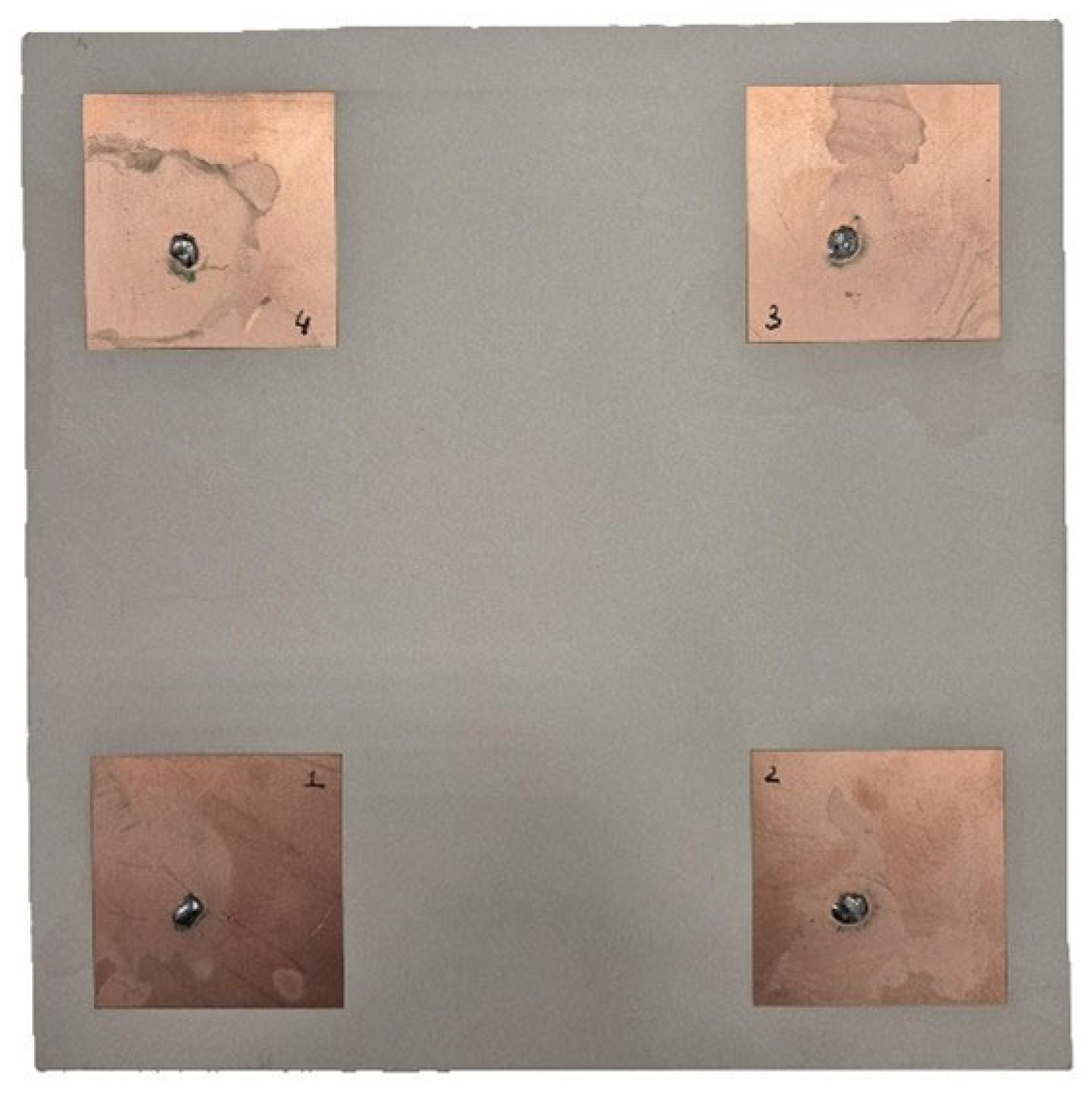
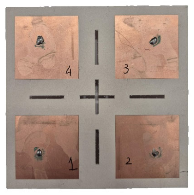
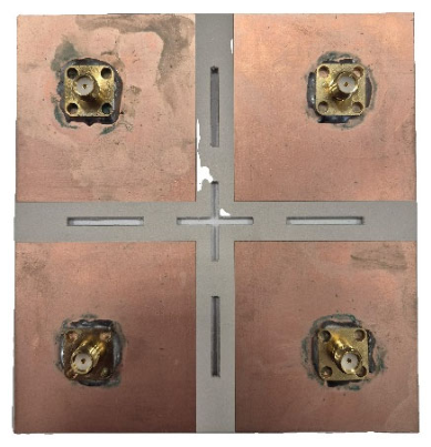
Following the final design and optimum miniaturized CRPA design in the simulation environment, the manufacturing phase was initiated. Manufactured target miniature array is shown in Figure 32 and Figure 33. To maintain measurement consistency and facilitate element identification, antenna numbering annotations were incorporated onto the CRPA elements.
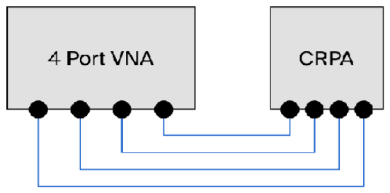
The impedance matching of the antennas and the isolation levels between antenna elements were measured by using a four-port Rohde & Schwarz (Rohde & Schwarz GmbH & Co. KG, Munich, Germany) ZNB40 network analyzer. The schematic of the measurement setup is presented in Figure 34. A four-port vector network analyzer (VNA) was employed as the primary measurement instrument, together with four phase-matched and amplitude-matched RF cables to ensure measurement consistency across all ports.
The impedance matching (S-parameters) and inter-element isolation measurements were conducted in a laboratory environment, with the antennas radiating into free space and positioned to minimize the influence of nearby reflective objects. A representative photograph showing the VNA together with the CRPA assemblies is also provided in Figure 35.
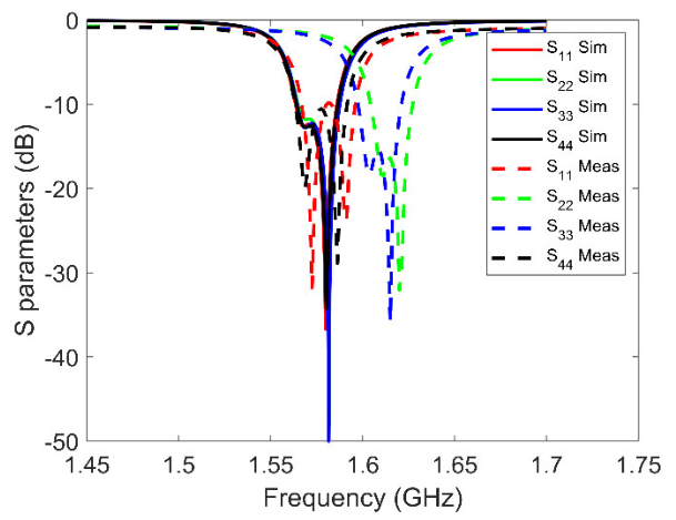
The measurement and simulation results related to the impedance matching of the antennas are presented in Figure 36. A detailed examination of the results revealed an observable shift in the antenna operating frequencies compared to the simulations. Antennas 2 and 3 exhibited similar characteristics, with their center frequencies obtained at approximately 1.595 GHz, corresponding to a 1.2% shift. For Antennas 1 and 4, the center frequencies were observed to be around 1.61 GHz, corresponding to a 2.2% shift. Since the magnitude and nature of these shifts differed from the trends observed in the simulation environment, the measurement setup was re-evaluated, and repeated trials led to the conclusion that the measurements were accurate. The measured S-parameters exhibit slight port-to-port frequency shifts, whereas simulations predict the same resonance for all ports. These discrepancies arise from practical implementation factors such as fabrication tolerances, especially the blob of solder, variations in feed lines and connectors, and uncertainties in substrate properties, which are common in multi-port patch antennas. Although these deviations do not have a notable impact on the overall antenna performance and, under normal circumstances, these results would allow the antennas to be tuned to the target frequency, the fact that the antennas are aligned in pairs within similar bands led to the conclusion that the effectiveness of the proposed method could at least be evaluated based on the isolation results between these antenna pairs.
Studies investigating the parametric variation in antenna characteristics and the corresponding shifts in operating frequency for antennas with similar design architectures are available in the literature [32]. These studies indicate that variations solely in the antenna length or width generally lead not only to a shift in the resonant frequency, but also to degradation in both the impedance matching characteristics and circular polarization performance. In contrast, for cases such as the present study, where the impedance matching characteristics remain largely preserved while only the center frequency exhibits a shift, the same studies report that variations in the dielectric constant are the most probable cause. Accordingly, it has been demonstrated that an approximately 3% variation in the dielectric constant may result in a frequency shift on the order of 1.2%. However, in the present measurements, two antennas exhibit a relatively larger frequency shift with similar characteristics, while the other two antennas exhibit a comparatively smaller shift, also with similar characteristics. Therefore, it is considered unlikely that the observed behavior is directly related to the dielectric constant variation. This assessment is supported by the fact that Rogers substrates are known to exhibit a highly homogeneous material distribution, and the dielectric constant is generally consistent within the same sample. One of the primary objectives of the planned future studies will be the detailed investigation and mitigation of these frequency shifts and the design of antennas with wider bandwidths to tolerate small frequency shifts.
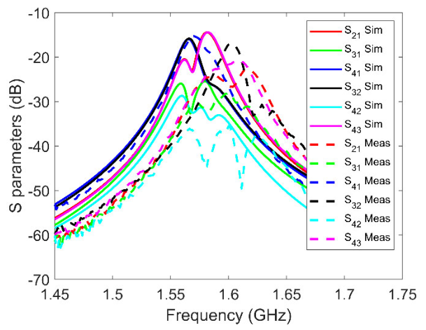
The results for mutual coupling between the antennas, including both the measurements and simulations, are also indicated in Figure 37. The isolation levels at the frequencies where the mutual isolation between the antennas is the lowest are presented in Table 5.
As mentioned earlier, although antenna pairs (1 and 4, 2 and 3) displayed similar characteristics, the shift in their center frequencies prevented a complete comparison of all isolation results with the simulations. Nevertheless, the fact that Antennas 1 and 4 and 2 and 3 showed comparable characteristics made the observed agreement between the S14 and S23 results and the simulations particularly valuable, supporting the conclusion that the simulated design performance was reasonably reliable.
According to the measurements conducted on the fabricated CRPA, it is observed that the operating frequencies of the antennas exhibited an observable shift relative to the simulated result. However, the impedance matching was maintained at the shifted frequency. Under normal circumstances, since the single antenna and the array antenna were manufactured from the same substrate, and no such frequency shift was observed in the single antenna, such a shift was not expected in the array process, making the results somewhat surprising. For this reason, the patch dimensions, which are among the most likely sources of the frequency shift, were measured by using a high-precision instrument, and it was confirmed that they were manufactured in accordance with the design parameters. Normally, a final tuning procedure could be applied to adjust the antennas to the target center frequency range. Nevertheless, since the obtained isolation results showed a high degree of similarity with the simulations, it was concluded that the target performance criteria were met, and that a miniature CRPA design—comprising four elements, featuring coupling-mitigation measures, and achieving isolation levels comparable to a standard half-wavelength-spaced CRPA of nearly single-element dimensions—was successfully realized.
It is well known that modern GPS antennas are increasingly designed with wideband or multiband characteristics to support multiple GNSS systems simultaneously. In the present study, however, the primary focus was placed on antenna miniaturization and mutual coupling reduction. Furthermore, the design was constrained to a single-layer and uniform-thickness substrate configuration in order to preserve structural simplicity and low-profile characteristics. Consequently, bandwidth enhancement studies remained limited within the scope of this work, which reduced the antenna’s tolerance against minor frequency shifts. Nevertheless, it is anticipated that the proposed method could provide even more effective performance when applied to wider-band GNSS antenna structures designed with fewer structural constraints. Investigation of the proposed approach under wideband and multiband GNSS antenna configurations is therefore considered as part of future work.
In the manufacturing phase, both the reference and miniature CRPA designs were fabricated. Although a noticeable frequency shift was observed in both CRPA designs compared to the expected operational frequency, the inter-element isolation levels closely matched the simulation results, eliminating the need for additional tuning.
The dimension comparisons of the fabricated prototypes of the designed miniature CRPA and the reference CRPA are presented in Figure 38. As can be seen, the miniature CRPA design offers a significant size advantage compared to the reference half-wavelength-spaced CRPA.
Furthermore, the results of the study presented in this paper, within the scope of CRPA miniaturization and/or inter-antenna coupling-reduction, are compared with those reported in the literature and summarized in Table 6. Based on a comprehensive literature review, it is observed that the number of studies focusing on CRPA miniaturization remains limited. Therefore, the comparative analysis presented in this work is conducted by considering only the most prominent studies that provide sufficiently mature and comparable performance data. As shown in this table, the idea proposed in this work introduces a novel aspect through the hybrid application of different coupling-reduction techniques with decreasing inter-element spacing. Furthermore, while many studies do not provide a comparison with a reference CRPA in terms of performance evaluation criteria, the study presented herein distinguishes itself in this regard. With respect to CRPA miniaturization performance, inter-antenna isolation data are of critical importance; nevertheless, it is evident that several studies in the literature did not present such data. In contrast, within the scope of this study, isolation has been regarded as one of the most critical parameters, serving as a basis for the interpretation of both coupling-reduction and the final CRPA design. The results demonstrate that the proposed design outperforms comparable CRPAs of similar sizes. This distinctive aspect further underscores the contribution of this work. Unlike the studies in the literature, this work distinguishes itself and demonstrates originality by successfully implementing multiple coupling-reduction measures within the same design, achieving substantially reduced dimensions, providing higher isolation compared to studies of similar size, presenting all performance-critical data in a comprehensive manner, and including a reference-dimension CRPA design for internal benchmarking and comparison.

6. Conclusions

This study was conducted with the objective of developing a miniaturized CRPA design to facilitate the integration of CRPA-supported systems, intended to maintain the operational functionality of GNSS receivers under jamming threats, especially in platforms with spatial size constraints. The reduction in size within the CRPA design was achieved through the miniaturization of individual antenna elements and by decreasing the inter-element spacing, while simultaneously seeking to suppress or mitigate the increased mutual coupling resulting from the closer proximity of the antenna elements.
As the first step in the study, a miniature unit antenna was designed by using Rogers RO3006 substrate with an approximately square-patch architecture, and the design was validated through fabrication. Subsequently, a reference CRPA design with a conventional half-wavelength spacing between elements was implemented to evaluate the effectiveness of the proposed miniaturization and coupling suppression techniques. The design dimensions were optimized according to target performance metrics.
In the following stages, various design techniques were applied to identify the most effective method for reducing mutual coupling between antenna elements. These techniques included introducing slots between antennas, implementing substrate and ground discontinuities, applying EBG structures, absorber materials, metallic walls, and rotating antenna elements. The effectiveness of each method was comparatively evaluated. Ultimately, an integrated and optimized miniature CRPA design was realized with 0.3-wavelength spacing between antenna elements, incorporating inter-element slots, ground-plane segmentation and element rotation. The resulting structure achieved mutual coupling levels that are larger than 18.5 dB which is much larger than the mutual coupling value (>14.4 dB) of the reference CRPA with 0.5 λ separation, thus validating its performance within the design environment.
Following this, the manufacturing phase was initiated, and both the reference and miniature CRPA designs were fabricated. It is observed that the inter-element isolation levels closely matched the simulation results, eliminating the need for additional tuning. Moreover, the results indicate that the miniature CRPA design offers a significant size advantage compared to the reference half-wavelength-spaced CRPA.
The idea proposed in this work introduces a novel aspect through the hybrid application of different coupling-reduction techniques with decreasing inter-element spacing. The key contribution of this work is that it integrates multiple coupling-reduction techniques within a single design framework, achieves significant size reduction, provides improved isolation compared to studies with comparable dimensions, presents all performance-critical metrics in a comprehensive manner, and includes a reference-sized CRPA design for internal benchmarking and comparative evaluation.
In summary, unlike many studies in the literature, this work both presents a uniquely designed miniature CRPA and develops a corresponding reference CRPA to enable performance comparison, thereby allowing for an effective validation of the proposed design. Furthermore, in contrast to prior research, a wide variety of mutual coupling-mitigation techniques were explored, compared, and integrated into the final design through a hybrid approach.
Within the scope of this study, the primary focus has been the high-performance miniaturization of CRPAs, which constitute a key component of GPS anti-jamming systems. To demonstrate the impact of this miniaturization on overall system performance more clearly, it is necessary to investigate the radiation patterns obtained when antenna weight coefficients—derived from an anti-jamming algorithm operating in the backend—are applied to the proposed antenna structure as a future study.
Future academic work may also focus on increasing the effective bandwidth in the GNSS L1 band and updating the unit antenna design to support different GNSS systems and frequency ranges, with the objective of incorporating these updates into the miniature CRPA system.

Author Contributions

Conceptualization, Ö.C.D.; methodology, Ö.C.D. and S.C.; software, Ö.C.D. and S.C.; validation, Ö.C.D. and S.C.; formal analysis, Ö.C.D. and S.C.; investigation, Ö.C.D. and S.C.; resources, Ö.C.D. and S.C.; data curation, Ö.C.D.; writing—original draft preparation, Ö.C.D.; writing—review and editing, Ö.C.D., S.C. and M.Ü.; visualization, Ö.C.D. and S.C.; supervision, S.C. and M.Ü. All authors have read and agreed to the published version of the manuscript.

Funding

This research received no external funding.

Data Availability Statement

The data presented in this study are available from the corresponding author upon reasonable request.

Acknowledgments

We would like to thank ASELSAN for the company’s support during the manufacturing and measurement processes of this study. The authors also express their gratitude to Asım Egemen YILMAZ and Hayrullah YILDIZ for their academic guidance and valuable comments throughout the course of this work.

Conflicts of Interest

Author Ömer C. Dabak was employed by the company ASELSAN Inc., The remaining authors declare that the research was conducted in the absence of any commercial or financial relationships that could be construed as a potential conflict of interest.

References

  1. Gao, G.X.; Sgammini, M.; Lu, M.; Kubo, N. Protecting GNSS Receivers from Jamming and Interference. Proc. IEEE 2016, 104, 1327–1338. [Google Scholar] [CrossRef]
  2. Inside GNSS. CRPA for GNSS: Benefits, Challenges and Testing. 10 March 2022. Available online: https://insidegnss.com/crpa-for-gnss-benefits-challenges-and-testing/ (accessed on 15 May 2026).
  3. Wang, X.; Li, J.; Chen, W.; Zhang, M.; Chen, J.; Zhang, A. The Effect of Mutual Coupling on the Performance of GNSS Antenna Arrays. IEEE Access 2020, 8, 20480–20487. [Google Scholar] [CrossRef]
  4. Zhou, Y.; Chen, C.-C.; Volakis, J.L. Single-fed circularly polarized antenna element with reduced coupling for GPS arrays. IEEE Trans. Antennas Propag. 2008, 56, 1469–1472. [Google Scholar] [CrossRef]
  5. Capet, N.; Martel, C.; Sokolof, J.; Pascal, O. HIS-like resonator for mutual coupling reduction in compact arrays. In Proceedings of the 15th International Symposium on Antenna Technology and Applied Electromagnetics, Toulouse, France, 25–28 June 2012. [Google Scholar]
  6. Martel, C. Low Profile Array with Integrated High Impedance Surfaces For High Performance Adaptive GNSS. In Proceedings of the 9th European Conference on Antennas and Propagation (EuCAP), Lisbon, Portugal, 13–17 April 2015. [Google Scholar]
  7. Caizzone, S. Compact E5a/E1 antenna array for GNSS applications. In Proceedings of the 2016 10th European Conference on Antennas and Propagation (EuCAP), Davos, Switzerland, 10–15 April 2016; IEEE: Piscataway, NJ, USA, 2016; pp. 1–3. [Google Scholar] [CrossRef]
  8. Shao, X.; Yao, Y.; Yu, J.; Chen, X.; Liu, X.; Qi, L.; Chen, Z. Compact Triple Band Antenna Array for GNSS Application. In Proceedings of the IEEE International Conference on Microwave and Millimeter Wave Technology (ICMMT), Beijing, China, 5–8 June 2016. [Google Scholar]
  9. Würth Elektronik. ANR017 GNSS Antenna Selection; Würth Elektronik: Waldenburg, Germany, 2020. [Google Scholar]
  10. Balanis, C.A. Antenna Theory; A John Wiley & Sons Publication: Hoboken, NJ, USA, 2005. [Google Scholar]
  11. Lo, Y.T.; Engst, B.; Lee, R.Q. Technical memorandum: Simple design formulas for circularly polarised microstrip antennas. IEE Proc. H Microw. Antennas Propag. 1988, 135, 213–215. [Google Scholar] [CrossRef]
  12. Dabak, Ö.C.; Erdem, F.; Sönmez, T.; Alatan, L.; Koç, S.S. Interference suppression in a GPS receiver with 4 element array design and implementation of beamforming algorithms. In Proceedings of the 2016 IEEE/ION Position, Location and Navigation Symposium (PLANS), Savannah, GA, USA, 11–14 April 2016; IEEE: Piscataway, NJ, USA, 2016; pp. 645–652. [Google Scholar] [CrossRef]
  13. Maloney, J.G.; Baker, B.N.; Acree, J.J.; Schultz, J.W.; Little, J.A.; Reuster, D.D. Fragmented aperture antenna design of miniaturized GPS CRPA: Model and measurements. In Proceedings of the 2007 IEEE Antennas and Propagation Society International Symposium, Honolulu, HI, USA, 9–15 June 2007; IEEE: Piscataway, NJ, USA, 2007; pp. 3784–3787. [Google Scholar] [CrossRef]
  14. Guo, L.; Tan, P.-K.; Chio, T.-H. A compact 8-element antenna array for GPS digital beamforming. In Proceedings of the 2012 International Symposium on Antennas and Propagation (ISAP), Nagoya, Japan, 29 October–2 November 2012; IEEE: Piscataway, NJ, USA, 2012; pp. 850–853. [Google Scholar]
  15. Hehenberger, S.P.; Elmarissi, W.; Caizzone, S. Design and Installed Performance Analysis of a Miniaturized All-GNSS Bands Antenna Array for Robust Navigation on UAV Platforms. Sensors 2022, 22, 9645. [Google Scholar] [CrossRef] [PubMed]
  16. Madni, A.; Khan, W.T. Design of a Compact 4-Element GNSS Antenna Array With High Isolation Using a Defected Ground Structure (DGS) and a Microwave Absorber. IEEE Open J. Antennas Propag. 2023, 4, 779–791. [Google Scholar] [CrossRef]
  17. Madni, A.; Khan, W.T. A High Efficiency and Low Mutual Coupling Four-Element Antenna Array for GNSS Applications. Prog. Electromagn. Res. Lett. 2024, 116, 63–70. [Google Scholar] [CrossRef]
  18. Raza, M.U.; Zhang, K.; Yan, S. Metasurface-assisted mutual coupling suppression in circularly polarized MIMO antenna array for Sub-6 GHz applications. Mater. Des. 2024, 248, 113445. [Google Scholar] [CrossRef]
  19. Lafmejani, M.R.; Zakeri, B.; Nooramin, A.S. The implementation of wide angle and UWB retrodirective performance based on non-uniformly spaced Van Atta array. IEEE Access 2025, 13, 211996–212003. [Google Scholar] [CrossRef]
  20. Cai, X.; Zhao, Q.; Xu, P.; Geyi, W. Synthesis of Cosecant-Squared Pattern with a Compact Linear Array Using the Extended Method of Maximum Power Transmission Efficiency. IEEE Antennas Wirel. Propag. Lett. 2025, 24, 863–867. [Google Scholar] [CrossRef]
  21. Luo, S.; Pedersen, G.F.; Zhang, S. Massive MIMO Array Design with High Isolation by Using Decoupling Cavity. IEEE Trans. Circuits Syst. II Express Briefs 2023, 70, 974–978. [Google Scholar] [CrossRef]
  22. Wang, H.; Zheng, Q.; Li, Q.; Yang, X.-X. Isolation Improvement and Bandwidth Enhancement of Dual-Band MIMO Antenna Based on Metamaterial Wall. IEEE Antennas Wirel. Propag. Lett. 2025, 24, 1144–1148. [Google Scholar] [CrossRef]
  23. Singh, N.; Padhy, S.; Chaubey, A.K. Isolation Enhancement of Microstrip Patch Antenna Array Using M-Type Barium Hexaferrite for Continuous Wave Radar Applications. In Proceedings of the 2025 IEEE Microwaves, Antennas, and Propagation Conference (MAPCON), Kochi, India, 14–18 December 2025. [Google Scholar]
  24. Lin, L.-X.; Tu, Z.-H.; Zhu, H. Isolation Enhancement in Millimetre-wave MIMO Array Base on Array-Antenna Decoupling Surface. In Proceedings of the 2022 IEEE MTT-S International Microwave Workshop Series on Advanced Materials and Processes for RF and THz Applications (IMWS-AMP), Guangzhou, China, 27–29 November 2022. [Google Scholar]
  25. Abdelgwad, A.H.; Hassan, M.A. Coupling Reduction and Bandwidth Enhancement of a MIMO Antenna with a Parasitic Element. Electronics 2026, 15, 158. [Google Scholar] [CrossRef]
  26. Hu, Y.; Wang, Y.; Zhang, L.; Li, M. Design of Miniaturized and Wideband Four-Port MIMO Antenna Pair for WiFi. Micromachines 2024, 15, 850. [Google Scholar] [CrossRef] [PubMed]
  27. Lin, C.-K.; Lin, D.-B.; Lin, H.-C.; Lin, C.-C. Design of a Compact Multiband Monopole Antenna with MIMO Mutual Coupling Reduction. Sensors 2024, 24, 5495. [Google Scholar] [CrossRef] [PubMed]
  28. Khan, M.K.; Liu, S.; Khan, M.I. A Wideband Eight-Port MIMO Antenna with Reduced Mutual Coupling for Future 5G mm-Wave Applications. Sensors 2025, 25, 484. [Google Scholar] [CrossRef] [PubMed]
  29. Xia, H.; Fan, H.; Liu, Z.; Miao, H.; Song, Z. Design of a 5G MIMO Mobile Intelligent Terminal Antenna with Metasurface Loading. Sensors 2025, 25, 2927. [Google Scholar] [CrossRef] [PubMed]
  30. Kapusuz, K.Y.; Can, S.; Şen, Y.; Yılmaz, A.E. K Bant Dizi Anten Tasarımında Mantar Şekilli EBG Yapısı ile Karşılıklı Bağlaşım Etkilerinin Azaltılması. In Proceedings of the URSI Türkiye 2016 Scientific Congress and National General Assembly (URSI TR 2016), Ankara, Türkiye, 1–3 September 2016. [Google Scholar]
  31. Razavizadeh, S.M. Dispersion Curve Using CST Microwave Studio: QuickGuide; ResearchGate: Berlin, Germany, 2014. [Google Scholar]
  32. Dabak, Ö.C. Design of Smart Antenna Array for Interference Suppression in GPS. Master’s Thesis, Middle East Technical University, Ankara, Türkiye, 2016. [Google Scholar]
  33. Awais, M.; Madni, A.; Khan, W.T. Design of a Compact High Isolation 4-Element Wideband Patch Antenna Array for GNSS Applications. IEEE Access 2022, 10, 13780–13786. [Google Scholar] [CrossRef]
  34. Kasemodel, J.A.; Chen, C.-C.; Gupta, I.J.; Volakis, J.L. Miniature Continuous Coverage Antenna Array for GNSS Receivers. IEEE Antennas Wirel. Propag. Lett. 2008, 7, 592–595. [Google Scholar] [CrossRef]
  35. Fasenfest, K.D. Miniature GNSS antenna arrays using multi-mode antenna elements. In Proceedings of the 2016 17th International Symposium on Antenna Technology and Applied Electromagnetics (ANTEM), Montreal, QC, Canada, 10–13 July 2016; IEEE: Piscataway, NJ, USA, 2016; pp. 1–2. [Google Scholar]
  36. Lee, T.; Lee, D.-H.; Choo, H.; Byun, G. A Method of Substrate Shaping to Improve Gain of Active-Element Pattern for Small Arrays. IEEE Antennas Wirel. Propag. Lett. 2017, 16, 1601–1604. [Google Scholar] [CrossRef]
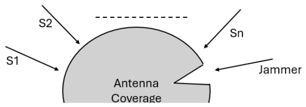
Figure 1. CRPA pattern while suppressing the jammer.
Electronics 15 02352 g001
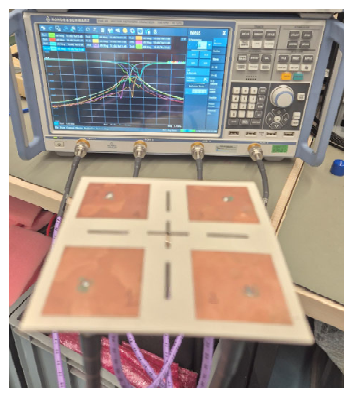
Figure 2. Top view and critical dimensions for generic probe-fed patch.
Electronics 15 02352 g002
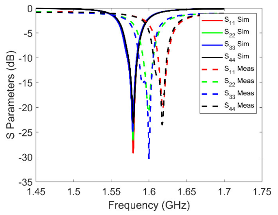
Figure 3. Axial ratio simulation result of RHCP unit antenna element.
Electronics 15 02352 g003
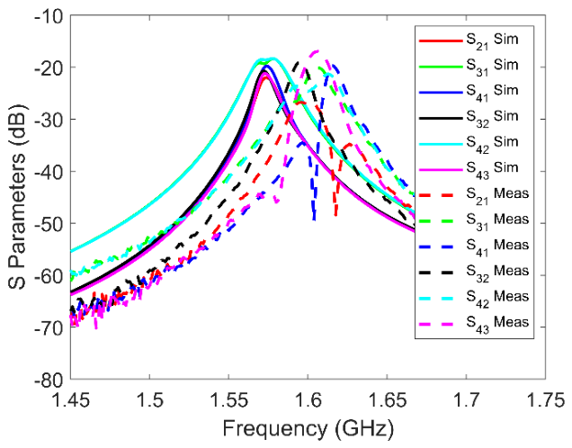
Figure 4. Manufactured antenna top view (Left) and bottom view (Right).
Electronics 15 02352 g004
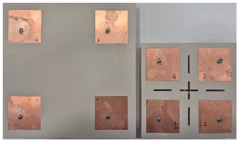
Figure 5. Single element |S11| parameters in dB (simulation vs. measurement result).
Electronics 15 02352 g005
Figure 6. Top view (Left) and bottom view (Right) of the reference CRPA design.
Electronics 15 02352 g006
Figure 7. Return loss parameters for the antenna elements in reference CRPA.
Electronics 15 02352 g007
Figure 8. Isolation levels for the antenna elements in reference to CRPA.
Electronics 15 02352 g008
Figure 9. Axial ratio for the antenna elements in reference CRPA.
Electronics 15 02352 g009
Figure 10. S-parameters for impedance matching of the miniature CRPA (0.3 λ spacing based on reference CRPA).
Electronics 15 02352 g010
Figure 11. Isolation between antenna elements of the miniaturized CRPA (0.3 λ spacing based on reference CRPA).
Electronics 15 02352 g011
Figure 12. Axial ratio of the miniature CRPA (0.3 λ spacing based on reference CRPA).
Electronics 15 02352 g012
Figure 13. Method 1—separate ground and substrate (top view).
Electronics 15 02352 g013
Figure 14. Method 2—separate substrate and common ground (top view).
Electronics 15 02352 g014
Figure 15. Method 3—EBG (Electromagnetic Band Gap) separation (top view).
Electronics 15 02352 g015
Figure 16. Method 4—separate ground and common substrate (bottom view).
Electronics 15 02352 g016
Figure 17. Method 5—metallic wall for isolation.
Electronics 15 02352 g017
Figure 18. Method 6—separate ground and substrate and antenna rotation (top view).
Electronics 15 02352 g018
Figure 19. Method 7—absorber wall for isolation.
Electronics 15 02352 g019
Figure 20. Top view of the final miniature CRPA.
Electronics 15 02352 g020
Figure 21. Bottom view of the final miniature CRPA.
Electronics 15 02352 g021
Figure 22. Return loss parameters for the antenna elements in the final miniature CRPA.
Electronics 15 02352 g022
Figure 23. Isolation levels for the antenna elements in the final miniature CRPA.
Electronics 15 02352 g023
Figure 24. Axial ratio simulation for the final miniature CRPA.
Electronics 15 02352 g024
Figure 25. Current distribution for reference CRPA.
Electronics 15 02352 g025
Figure 26. Current distribution for final and optimum CRPA.
Electronics 15 02352 g026
Figure 27. 3D-shaped pattern with suppressed jammer direction.
Electronics 15 02352 g027
Figure 28. 2D-shaped pattern with suppressed jammer (theta 90 cut).
Electronics 15 02352 g028
Figure 29. Manufactured reference array.
Electronics 15 02352 g029
Figure 30. Measurement vs. simulation results for impedance matching of the reference antenna array.
Electronics 15 02352 g030
Figure 31. S-Parameters for isolation between antennas (measurement vs. simulation).
Electronics 15 02352 g031
Figure 32. Top view of manufactured target miniature array.
Electronics 15 02352 g032
Figure 33. Bottom view of manufactured target miniature array.
Electronics 15 02352 g033
Figure 34. Test setup.
Electronics 15 02352 g034
Figure 35. Test setup with final CRPA.
Electronics 15 02352 g035
Figure 36. Measurement vs. simulation results for impedance matching of the manufactured target miniature array.
Electronics 15 02352 g036
Figure 37. S-Parameters for isolation between antennas of manufactured target miniature array (measurement vs. simulation).
Electronics 15 02352 g037
Figure 38. Top view of manufactured CRPAs ((Left): reference, (Right): miniaturized).
Electronics 15 02352 g038
Table 1. Isolation level comparison in terms of different methods.
Design MethodIsolation Levels
Reference CRPA>14.7 dB
Method 1>20.8 dB
Method 2>14.6 dB
Method 3>14.0 dB *
Method 4>17.2 dB
Method 5>22.6 dB
Method 6>28.6 dB
Method 7>22.6 dB
* The given isolation value is not comparable with other results since the value is given for a two-element design.
Table 2. Isolation level comparison in terms of different methods (considering all antennas).
S21S31S41S32S42S43
Reference CRPA<−14.7<−25.3<−15.1<−15<−27.9<−14.7
Method 1 <−21<−28.9<−20.8<−20.8<−32<−21
Method 2<−14.6<−25.1<−15<−15<−27.8<−14.7
Method 3<−14N/AN/AN/AN/AN/A
Method 4<−17.2<−19.2<−17.9<−17.9<−18.7<−17.2
Method 5<−22.7<−25.7<−22.8<−22.8<−28.1<−22.6
Method 6<−28.6<−30<−28.6<−28.6<−30<−28.6
Method 7<−22.6<−25.8<−22.7<−22.7<−28.3<−22.6
Table 3. Antenna weighting set for a specific jammer suppression scenario.
AntennaMagnitudePhase
11−36.1
20.36595−90
31−144.9
40.3659590
Table 4. Isolation levels for cross S-parameters.
S-ParameterIsolation (Sim)Isolation (Meas)
S2114.44 dB22.68 dB
S3125.41 dB28.01 dB
S4115.97 dB15.25 dB
S3215.84 dB17.08 dB
S4228.71 dB35.53 dB
S4314.43 dB20.81 dB
Table 5. Isolation levels for cross S-parameters (final and optimum miniaturized CRPA).
S-ParameterIsolation
(Simulation)
Isolation
(Measurement)
S2122.02 dB26.75 dB
S3118.38 dB20.09 dB
S4119.78 dB19.7 dB
S3220.72 dB19.01 dB
S4218.36 dB21.29 dB
S4321.23 dB16.98 dB
Table 6. Comparison of main parameters and isolation results.
LiteratureSize (mm)Isolation (dB)CRD *CWRA **
[4]114 (⌀)NPFeed NetworkNo
[6]250 × 250>30HISYes
[7]100 × 100>15Metallic WallYes
[8]180 × 180>23Gnd SlotYes
[13]NPNPElement MiniaturizationNo
[14]150 (⌀)NPU-SlotNo
[15]100 (⌀)>15FeedNo
[16]125 (⌀)>25DGS + AbsorberYes
[17]125 (⌀)>24DGS + MetamaterialYes
[33]125 (⌀)>20Absorber, Rotated ElementsNo
[34]88.9 × 88.9NPNoneNo
[35]88.9 (⌀)NPElement MiniaturizationNo
[36]120 (⌀)NPSubstrate SeparationNo
Ref array150 × 150>14.4NoneN/A
Final
Array
104 × 104>18.38Gnd. Separation, Element Miniaturization, Antenna Rotation, SlotYes
* CRD: coupling reduction technique. ** CWRA: comparison with reference array.
Disclaimer/Publisher’s Note: The statements, opinions and data contained in all publications are solely those of the individual author(s) and contributor(s) and not of MDPI and/or the editor(s). MDPI and/or the editor(s) disclaim responsibility for any injury to people or property resulting from any ideas, methods, instructions or products referred to in the content.