Article

Design and Investigation of Electromagnetic Characteristics of a Field-Modulated Permanent Magnet Vernier Generator


Naval University of Engineering, Wuhan 430033, China
*
Author to whom correspondence should be addressed.
Electronics 2026, 15(11), 2306; https://doi.org/10.3390/electronics15112306
Submission received: 27 April 2026 / Revised: 19 May 2026 / Accepted: 24 May 2026 / Published: 26 May 2026

Abstract

This paper presents a 10 kW outer-rotor field-modulated permanent magnet vernier generator tailored for low-speed direct-drive applications. It employs an outer-rotor Spoke-array configuration, which effectively mitigates the leakage flux between adjacent pole pairs. First, the topology and operating principle of the proposed generator are elaborated. Analytical calculations of key design parameters are then performed to accelerate the modeling process. A systematic parametric sweep is conducted to optimize the motor parameters, based on which a 2D finite element analysis model is established. Comprehensive FEA simulations are carried out to investigate its flux regulation capability, static and dynamic characteristics, and permanent magnet demagnetization risk. The results demonstrate that the Spoke-array permanent magnet array effectively suppresses leakage flux, achieving a volumetric power density of 387.5 kW/m3, and the no-load back electromotive force achieves a peak amplitude of 270 V with a total harmonic distortion as low as 3.7%, which is significantly higher than that of conventional permanent magnet vernier generators. Finally, a 30-slot/23-pole prototype is fabricated and tested. The experimental results show excellent agreement with the simulation predictions, validating the effectiveness of the proposed design.

1. Introduction

To address the stringent requirements of low-speed direct-drive power supply in ocean current energy generation systems, strict demands are imposed on the core performance of ocean current generators, including high torque density, low-speed operation stability, high power quality, and adaptability to variable flow velocity conditions [1]. Due to the extremely low rated speed of ocean current turbines and the wide fluctuation range of flow velocity, generators are required to deliver high torque output at low speeds while exhibiting low total harmonic distortion (THD) of back electromotive force (back-EMF), reasonable inductance parameter matching, and low cogging torque characteristics to meet the stable power supply requirements of offshore microgrids [2].
The field-modulated permanent magnet vernier generator (FM-PMVG), based on the magnetic field modulation principle and magnetic gear effect, modulates the low-speed permanent magnet field of the rotor into a high-frequency working magnetic field via stator modulation teeth. It can induce high-amplitude back-EMF at extremely low speeds and exhibits a torque density 2–3 times that of conventional permanent magnet machines, perfectly resolving the contradiction between low speed and high power density [3]. Among them, the outer-rotor FM-PMVG has become the preferred topology for ocean current energy direct-drive power generation due to its direct coaxial integration with turbine impellers, large moment of inertia, and excellent heat dissipation conditions [4].
In recent years, researchers worldwide have conducted extensive investigations into FM-PMVG, achieving remarkable advances in topology innovation, performance optimization, and engineering applications. These efforts have laid a solid foundation for the development of low-speed direct-drive power generation technologies. Early research primarily focused on comparing the fundamental performance of conventional synchronous generators and PMSGs. The authors of [5] systematically analyzed the efficiency, torque ripple, and thermal characteristics of PMSGs, direct-drive PMSGs, and wound-rotor synchronous generators. The results demonstrated that PMSGs achieve an efficiency of up to 92.5% with a torque ripple of only 3.5%, and their thermal performance is significantly superior to that of wound-rotor synchronous generators, confirming the application potential of permanent magnet machines in low-speed direct-drive scenarios. Nevertheless, this study did not address the unique advantages offered by field-modulated topologies.
To address the inherent limitations of single-stator PMVGs, including low power factor and limited overload capability, the authors of [6] proposed a dual-stator topology. A comparative analysis with the single-stator configuration based on the air-gap permeance modulation mechanism revealed that the proposed structure achieves higher power factor and enhanced overload capability, along with superior loss characteristics and permanent magnet demagnetization resistance. However, this design employs an inner-rotor configuration, which is incompatible with the outer-rotor impeller coaxial integration required for ocean current energy harvesting applications. To further boost torque density, the authors of [7] introduced an innovative dual-winding and dual-permanent magnet composite structure. By leveraging the dual magnetic field modulation effect, this design significantly improved the torque density and power density of the machine, effectively reducing the capacity requirements of the back-end converter. Nevertheless, the increased structural complexity and manufacturing cost of this topology make it unsuitable for long-term reliable operation in harsh marine environments.
The authors of [8] presented a comprehensive investigation of split-tooth PMVG topologies, designing and fabricating a 12-slot/20-pole prototype. The 3D thermal field simulations and experimental results confirmed the excellent demagnetization resistance of the proposed machine. However, the split-tooth structure exhibits relatively low magnetic field modulation gain, which limits its ability to meet the high torque density requirements of ultra-low-speed ocean current energy applications. The authors of [9] systematically elucidated the intrinsic relationships between slot–pole combination, modulation ratio, magnetic field modulation harmonics, and harmonic torque contribution. Through global parameter optimization, the torque output capability of low-modulation-ratio machines was enhanced by 40%, providing valuable theoretical guidance for the electromagnetic design of PMVGs. However, this study did not specifically analyze the flux concentration effect and leakage flux characteristics of outer-rotor Spoke-array structures. To improve design efficiency, [10] developed an analytical method for calculating permanent magnet magnetic forces, enabling accurate prediction of forces during assembly. This approach significantly reduces parametric sweep duration and modeling time, and its accuracy was verified through comparison with finite element simulation results. Nevertheless, the method does not account for the unique magnetic circuit characteristics of Spoke-array tangential excitation structures, and its computational accuracy requires further improvement when applied to the topology proposed in this work.
To reduce the cogging torque and improve the torque density of the machine, a fractional-pole permanent magnet vernier machine with an asymmetric V-shaped permanent magnet was proposed in [11]. A three-segment stator structure was also adopted to mitigate the end effect of segmented stators. Similarly, [12] improved the machine torque by enhancing the permanent magnet flux linkage using a Y-shaped permanent magnet structure, resulting in a 22.54% increase in power factor and an 18.6% increase in torque. In terms of research methods, [13] combined the reluctance network model and equivalent magnetic circuit with the finite element method to accurately model the machine, and determined the rotor position using region selection.
However, existing studies still have obvious limitations. First, most studies focus solely on torque density improvement as a single optimization objective, with insufficient attention paid to power quality indicators critical for ocean current energy generation, such as back-EMF THD and inductance matching. The back-EMF THD of most prototypes still exceeds 10%, which cannot meet the power supply requirements of island microgrids [14]. Second, the design of demagnetization resistance and overload capability is inadequate, leading to easy local demagnetization of permanent magnets under complex marine conditions and consequent continuous degradation of generator performance [15]. Third, there is a lack of customized electromagnetic design studies tailored to the low-speed and variable operating conditions of ocean current energy, resulting in poor adaptability of optimization results to actual working conditions [16].
To address the above limitations, this paper proposes an outer-rotor spoke-array FM-PMVG suitable for low-speed direct-drive ocean current energy generation. The outer-rotor structure is adopted to increase the air-gap diameter and thus enhance the torque output capability. A 30-slot/23-pole slot–pole combination is selected to obtain a moderate pole ratio, balancing torque density and power factor. First, the field modulation principle of the machine is analyzed, and the main structural parameters of the generator are calculated. Then, combined with the parametric scanning design method in ANSYS2021R1, a parametric model of the machine is built, and the electromagnetic performance of the generator is simulated and analyzed. Finally, a prototype with a rated power of 10 kW and a rated speed of 65 r/min is fabricated, and the effectiveness of the proposed topology and optimization method is verified through no-load and load experiments. The research results can provide theoretical reference and technical support for the high-torque-density design of high-performance, low-speed direct-drive ocean current energy generators.

2. Field Modulation Principle and Parameter Calculation for FM-PMVG

2.1. Magnetic Field Modulation Principle

The fundamental principle of magnetic field modulation is as follows: the high-pole-number permanent magnet (PM) field generated by the rotor is modulated by the stator teeth, producing low-pole-number effective working harmonics that match the pole number of the stator windings. These harmonics couple with the stator windings to achieve electromechanical energy conversion [17]. For FM-PMVG, the slot–pole combination relationship among the number of stator modulation poles Z m , the number of rotor PM pole pairs p r , and the number of armature winding pole pairs p w must be satisfied:
Z m = p r + p w
The magnetic gear effect endows FM-PMVG with a torque density much higher than that of conventional permanent magnet synchronous generator (PMSG) of the same volume, making them highly suitable for low-speed high-torque applications.
The spoke-array permanent magnet vernier machine operates on the magnetic gear effect for magnetic field modulation. The PMs on the rotor side generate a low-speed rotating excitation field, whose spatial fundamental magnetomotive force (MMF) has a pole pair number of p r . When this field passes through the stator tooth-slot structure with Z m modulation poles, the permeance function periodically modulates the air-gap permeance, generating a rich spectrum of spatial harmonic magnetic fields in the air gap. After modulation, the pole pair numbers of the main harmonic components of the air-gap flux density satisfy
p m , k = k Z m ± p r ,   k = 0 , 1 , 2 ,
where p m , k denotes the pole pair number of the k = 1 harmonic component. The dominant working harmonic generated when k = 1 has a pole pair number of p m , 1 = Z m p r , which is exactly equal to the armature winding pole pair number p w , thus enabling effective coupling with the armature windings. At this point, the ratio of the rotational speed of the air-gap harmonic magnetic field to the mechanical angular velocity of the rotor is
ω m , 1 ω r = p r Z m p r = p r p w = G r
That is, the rotational speed of the working harmonic magnetic field is G r times the mechanical rotational speed of the rotor. This means that when the generator rotor rotates at a low speed, the frequency of the electromotive force (EMF) induced in the armature windings is equivalent to that of a pw-pole machine operating at a much higher speed. This achieves high-frequency voltage output under low-speed conditions, which is beneficial for reducing the machine volume.

2.2. Main Dimensions Design of FM-PMVG

The basic parameters of the generator are listed in the following Table 1. The design parameters of the generator are calculated based on the power-size equation of electrical machines.

2.2.1. Derivation of Power-Size Equation

The power-size equation of FM-PMVG is the core basis for determining the main geometric dimensions. For a three-phase AC generator, its electromagnetic power can be expressed as
P e m = m T 0 T e t i t d t
where m is the number of phases, e t is the phase back-EMF, and i t is the phase current. Considering the magnetic field modulation effect, the amplitude of the effective working harmonic flux density coupled with the winding in the air gap is B g 1 . Let D o s be the stator outer diameter and L e f be the effective core length; then, the fundamental flux per pole is
Φ 1 = 2 π B g 1 τ L e f = 2 π B g 1 π D o s 2 p w L e f = B g 1 D o s L e f p w
where τ = π D o s / 2 p w is the winding pole pitch.
Introducing the effects of magnetic field modulation and armature reaction, and referring to the derivation method of the power-size equation for vernier machines in reference [18], the apparent power of the generator can be expressed as
S = π 2 60 G r k w A s B g 1 D o s 2 L e f n N
Using Equation (6), the D o s 2 L e f of the machine can be obtained as
D o s 2 L e f = 60 S π 2 G r k w A s B g 1 n N
This equation shows that under the same electromagnetic loading, the power density of the vernier machine is Gr times that of the conventional permanent magnet synchronous machine, which reflects the amplification advantage of magnetic field modulation.

2.2.2. Determination of Main Dimensions

According to the design specifications, the rated power of the generator is 10 kW, the rated phase voltage is 270 V, the power factor is taken as cosφ = 0.95 (under power generation condition), and the efficiency is η = 0.92. Then, the apparent power and calculated power are
S = P N c o s φ
P = P N η cos φ
Substituting the values, P is calculated to be 11.44 kW.
(1)
Slot–Pole Combination:
The designed machine adopts a 30-slot/23-pole-pair structure. According to the calculation formula, the winding pole pair number is p w = 7 . A fractional-slot concentrated winding is used, with 30 slots for three phases and a slot number per pole per phase of q = 5 / 7 . For the concentrated winding of 30 slots and 14 winding poles, the fundamental winding factor is calculated as
k w = k d k p
where the distribution factor k d and pitch factor k p depend on the specific winding arrangement. The typical winding factor for a 30-slot/14-pole fractional-slot concentrated winding is approximately k w 0.933 .
(2)
Selection of Electric and Magnetic Loadings:
For low-speed permanent magnet generators, the electric loading A s is generally in the range of 40~75 kA/m. Considering that the machine adopts an outer-rotor structure with better heat dissipation conditions than the inner-rotor structure, the initial value of the A s is taken as 45 kA/m. The amplitude of the air-gap fundamental flux density B g 1 is limited by core saturation and permanent magnet material properties. For the Spoke-array flux-concentrating structure, B g 1 can be taken as 1.1~1.3 T, and 1.1 T is initially selected in this paper.
Substituting into Equation (7), taking G r as 3.286 and k w as 0.933, and setting the λ as 0.8, then
D o s = D o s 2 L e f λ 1 / 3
L e f = λ D o s
Therefore, the initial main dimensions of the machine are determined as D o s = 300 mm, L e f = 240 mm.
(3)
Stator Structure Design:
The stator adopts open trapezoidal slots with a total of 30 slots. The stator outer diameter is D o s = 300   m m . The stator yoke flux is half of the flux per pole. Taking the stator yoke flux density B y   a s   1.6   T , the stator yoke height is calculated as follows:
Flux per pole:
Φ p = 2 π B g 1 τ L e f
Stator yoke cross-sectional area:
S y = Φ p 2 B y
Stator yoke height:
h y = S y L e f k F e
where k F e = 0.97 is the lamination factor of silicon steel sheets. Rounding off, h y = 20   m m . Then, the stator inner diameter is
D i s = D o s 2 h s + h y
The stator slot height h s needs to be determined comprehensively by considering the slot area and tooth width. Taking the stator tooth flux density B t = 1.8   T , the tooth width is calculated as follows.
Circumferential pitch per stator tooth:
t s = π D o s Z m
Tooth width:
b t = t s B g 1 B t k F e
Slot opening width:
b s 0 = t s b t
Taking the slot opening width b s 0 = 12.0   m m
The determination of the h s needs to consider the slot area required for winding insertion. Let N s be the number of conductors per slot, I p h be the phase current RMS value, and the current density be taken as J = 5.0 A/mm2. The phase current is estimated from the power equation:
I p h = P N 3 U N η cos φ
The number of conductors per slot is N s = 2 m N p h / Z , where N p h is the number of series turns per phase. Considering the requirements of slot fill factor and current density, the required slot area is approximately 500~700 mm2, corresponding to h s as 50 mm.
(4)
Armature Winding Design
The stator adopts a three-phase fractional-slot concentrated winding with 30 slots and 14 poles, and the slot number per pole per phase is 5/7. The winding adopts a double-layer concentrated winding structure with a coil pitch y = 1 .
The relationship between the no-load back-EMF and the terminal voltage of the generator is
Φ m = B r w m L e f
where the induced electromotive force frequency is
f = n N p w G r 60
Taking the no-load back-EMF E 0 0.95 U p h , the number of series turns per phase is
N p h = E 0 4.44 f k w Φ 1
The number of conductors per slot is N s = 2 N p h / Z / 3 , which is rounded to 26.
(5)
Rotor Structure Design
The rotor adopts a Spoke-array tangential excitation structure with a total of 2 p r as 46 PM units uniformly distributed along the circumference. The PM material is sintered neodymium-iron-boron NdFeB36, which has a remanence B r from 1.18 to 1.22 T, a coercivity H c of 890 kA/m, and a maximum energy product B H max of 280~320 kJ/m3.
The rotor inner diameter is D o r = D o s + 2 g , where the air-gap length g is taken as 2.0 mm, so D o r is 304 mm. The rotor yoke thickness needs to meet the requirements of mechanical strength and magnetic circuit.
The PM size design is the key to the Spoke-array structure. The tangentially magnetized permanent magnets are placed along the radial direction, and their magnetization direction is along the circumferential tangential direction. Let the radial height of the permanent magnet be h m , the tangential width be w m , and the axial length be equal to the core length L e f . The flux per pole is provided by two adjacent permanent magnets in parallel. The total flux provided by the permanent magnets to the external magnetic circuit is
Φ m = B r w m L e f
The magnetomotive force of the permanent magnet is
F m = H c h m
According to the equivalent magnetic circuit principle, considering the magnetic voltage drops in the air gap, stator and rotor teeth, and yokes, the permanent magnet thickness can be estimated by the following formula:
h m = K s K δ B g 1 g μ 0 H c
where K s is the external magnetic circuit saturation factor, taken as 1.15–1.25; K δ is the air-gap factor, taken as 1.1–1.3; H c is the coercivity at the operating point of the permanent magnet. For the Spoke-array structure, the flux per pole provided by the permanent magnets due to the flux-concentrating effect is
Φ p = 2 B r w m L e f P c 1 + P c
where P c   is the permeance coefficient.
After comprehensive consideration, the w m as 12 mm and h m   a s   30 mm are taken.
The rotor yoke thickness is determined by both the magnetic circuit and mechanical strength. The rotor yoke carries half of the flux per pole. Taking the rotor yoke flux density B y r = 1.5   T , the yoke thickness is
h y r = Φ p 2 B y r L e f k F e
Rounding off, h y r = 13 mm.
Then, the rotor outer diameter is
D r o = D o r + 2 h y r + 2 h m
The rotor outer diameter is 390 mm.

2.3. Finite Element Simulation Modeling

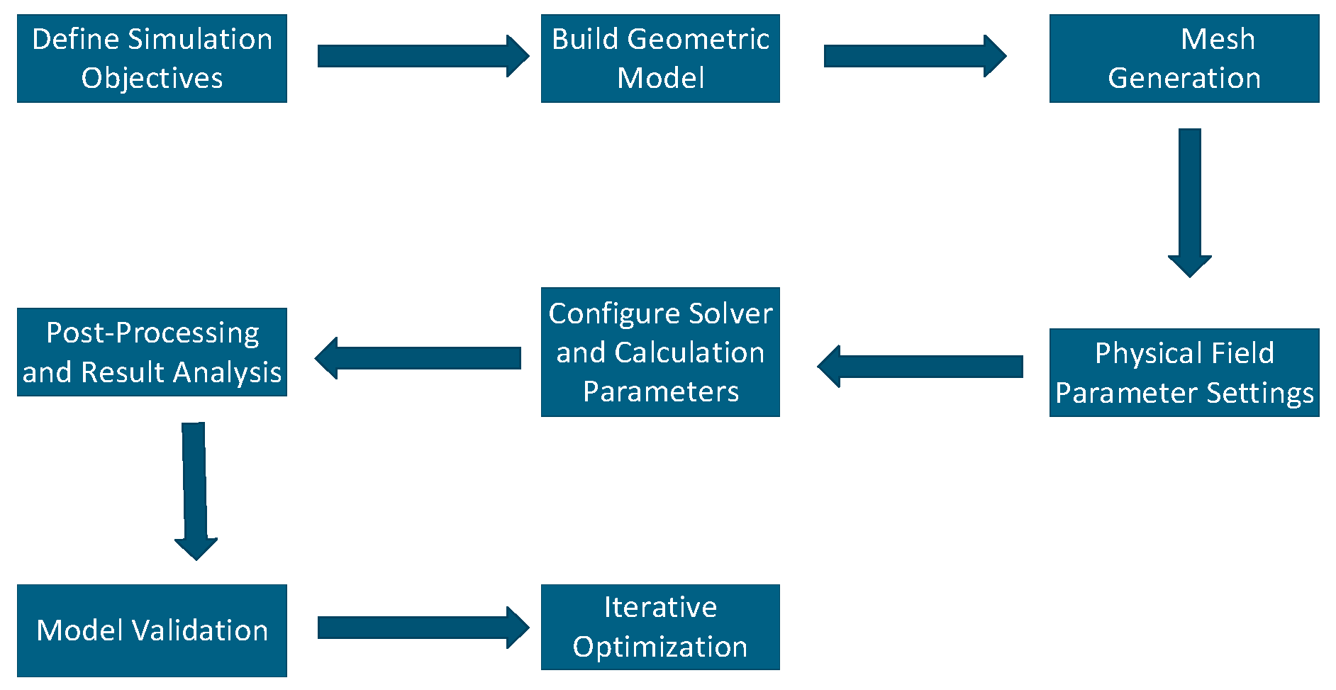
The finite element method (FEM) is an effective numerical method for solving initial and boundary value problems of partial differential equations. With the rapid development of computer science and technology, the application depth and breadth of FEM have been greatly expanded. It has become an important component of computer-aided engineering and exhibits significant advantages in the field of electrical engineering. Its prominent features are as follows: parametric sweep can be performed at the initial design stage, simplifying the manufacturing process and pre-solution difficulty of the machine; it is convenient to simulate and calculate the machine at different rotor position angles; and its powerful post-processing capability facilitates data export and analysis. The general solution steps of FEM are shown in the simulation modeling flowchart in Figure 1.
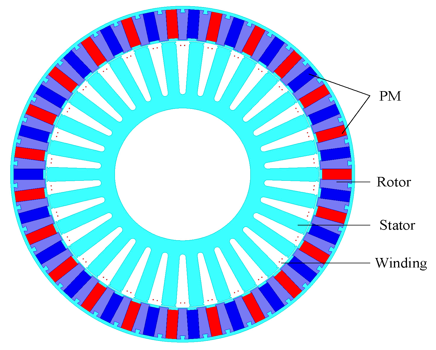
According to the design specification of 10 kW power for the machine, assuming a length-to-diameter ratio of 0.8 and a ratio of permanent magnet pole pairs to modulation pole pairs of 1, the stator outer diameter of the machine is estimated to be 310 mm. Combined with the parametric sweep modeling function of ANSYS Maxwell, the machine is modeled based on the above calculation results, as shown in Figure 2.
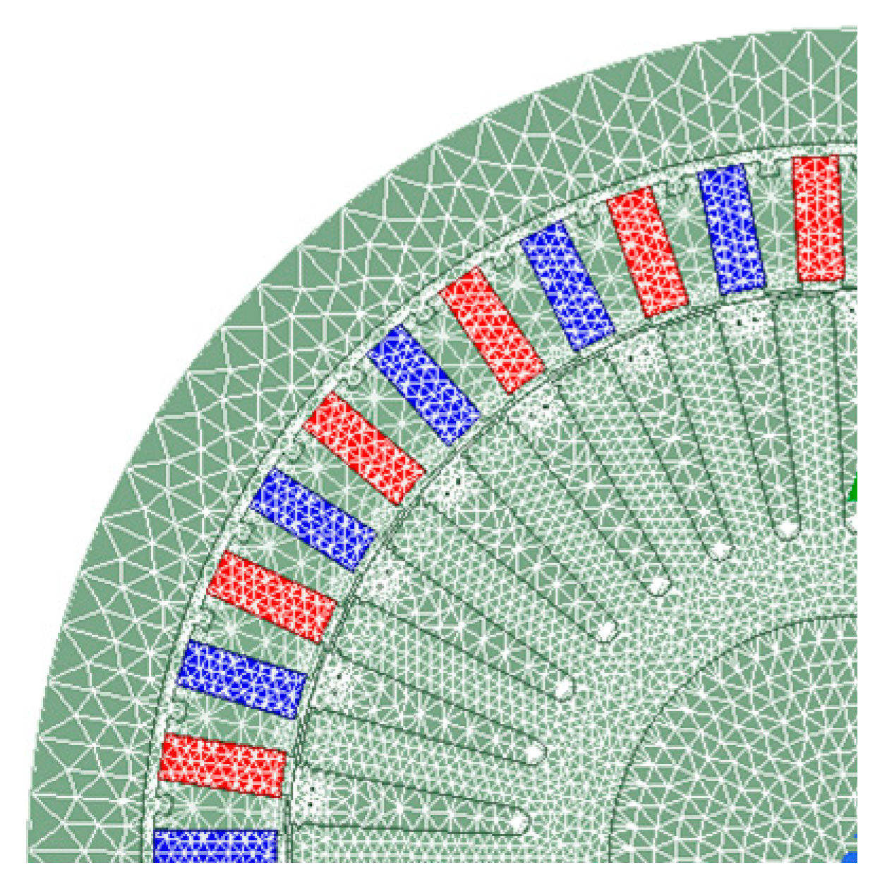
In the two-dimensional electromagnetic field finite element modeling process, the following key assumptions and mesh generation criteria must be followed. First, the quality of finite element mesh generation directly affects the convergence and calculation accuracy of the numerical solution. The air-gap region, which carries the main magnetic flux and has the largest magnetic field gradient, requires mesh refinement. As the core region of magnetic field energy conversion, the permanent magnet region has a mesh density second only to the air-gap region. The winding region requires appropriate refinement compared with the core region due to the significant skin effect of the current. The mesh generation result is shown in Figure 3.
Based on the analytical calculation results and the parametric sweep function of ANSYS Maxwell, the machine is optimized and modeled with the back-EMF amplitude and THD as the reference indicators.
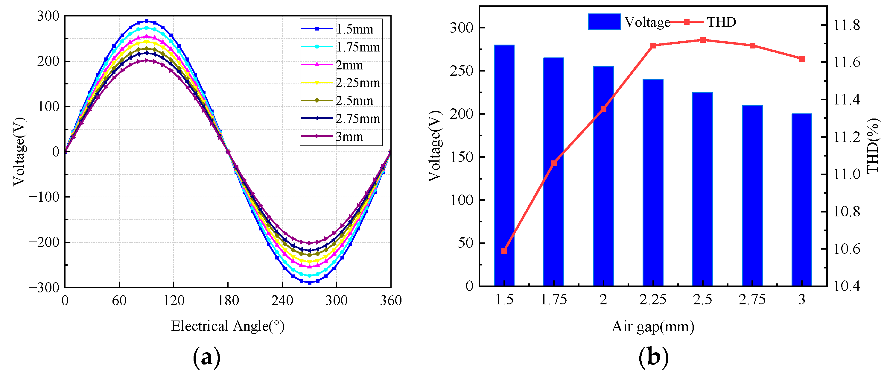
Figure 4 illustrates the influence of air-gap length on the back-EMF amplitude and THD of the proposed FM-PMVG. Parametric sweep simulations are performed over an air-gap range of 1.5 mm to 3 mm, with a step size of 0.25 mm. Considering both the design requirements and manufacturing feasibility, an air-gap length of 2 mm is selected.
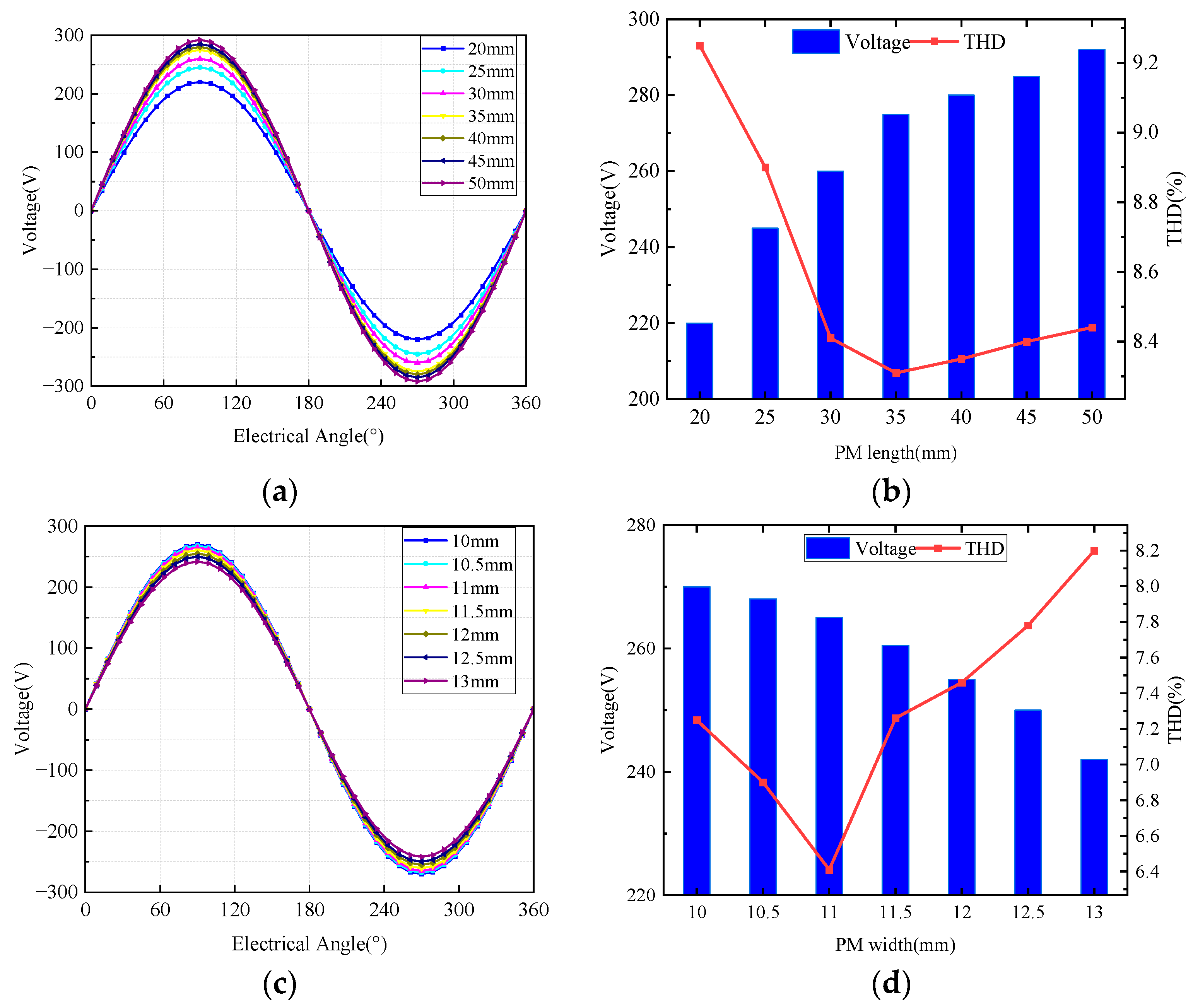
Figure 5 presents the effects of permanent magnet length and width on the generator performance. An excessively long magnet length or wide magnet width will lead to severe core saturation and introduce additional harmonic components. Therefore, the permanent magnet length is determined to be 35 mm.
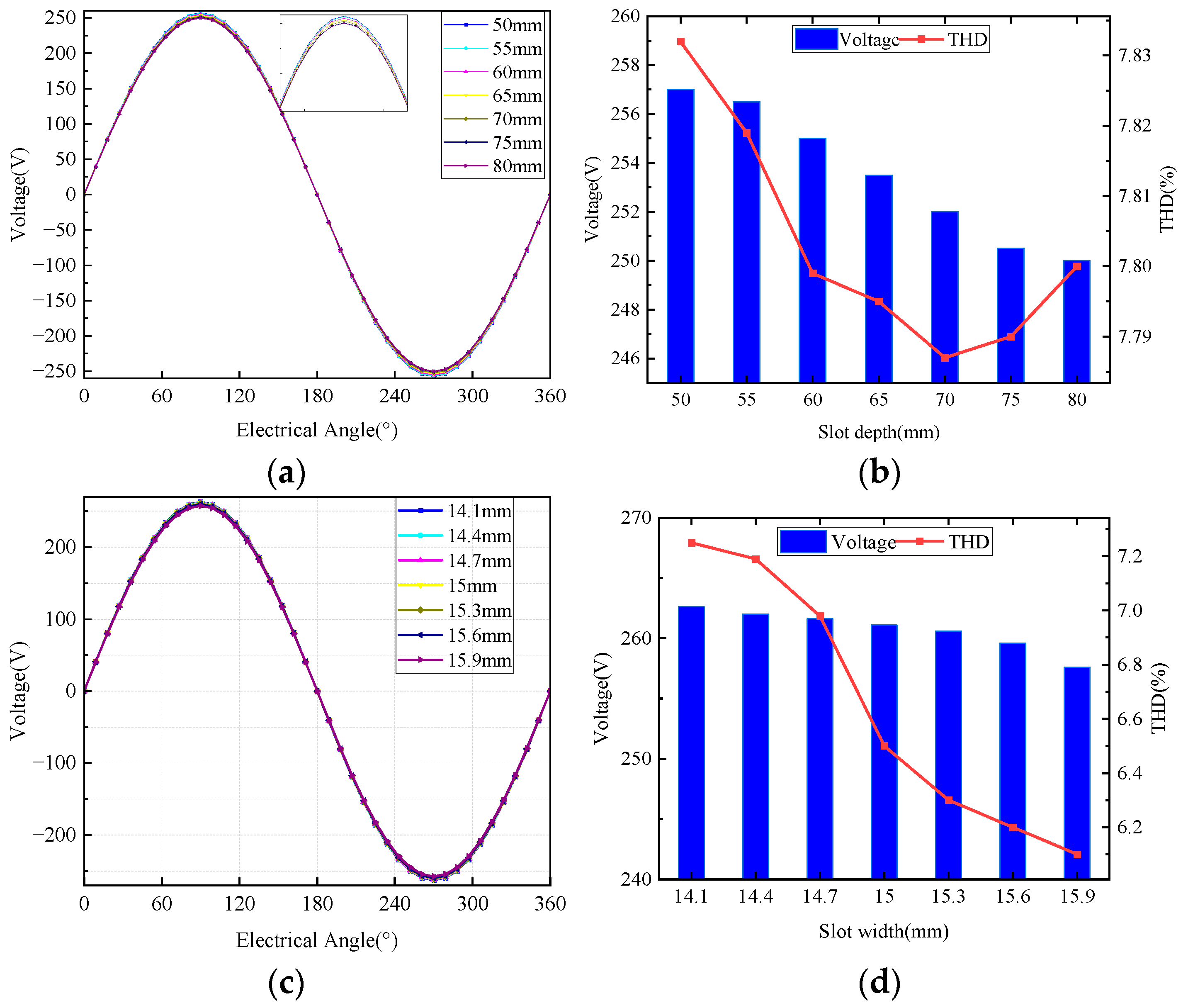
Figure 6 shows the influences of stator slot depth and width on the generator characteristics. Variations in these two geometric parameters directly alter the air-gap permeance waveform. The THD decreases gradually with increasing stator slot width. Taking the rated design voltage of the generator into account, the stator slot width is set to 15 mm, and the stator slot depth is set to 55 mm.
Through the calculation and parametric sweep process of the electrical machine, the main dimensions of FM-PMVG are listed in Table 2.

3. Electromagnetic Performance Analysis of the Machine

The electromagnetic rationality of the magnetic circuit topology is evaluated through finite element analysis (FEA) of the no-load permanent magnet excitation condition of the FM-PMVG in ANSYS Maxwell. The core of this analysis is to isolate the influence of armature windings by setting their excitation to zero, retaining only the excitation effect of permanent magnets. This allows quantitative analysis of the adaptability of the magnetic circuit to magnetic field distribution, leakage flux, and saturation characteristics.

3.1. Magnetic Field Distribution

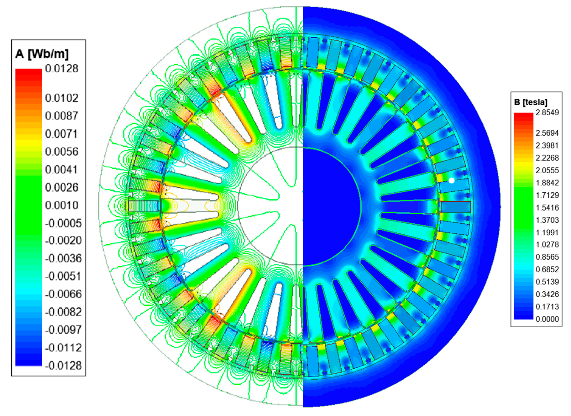
Figure 7 shows the no-load magnetic flux line diagram and magnetic flux density contour map of the FM-PMVG. It can be seen that the magnetic flux lines of the FM-PMVG are symmetrically and uniformly distributed, and almost all pass between adjacent magnetic poles. The rotor has 23 pole pairs of permanent magnets and the stator has 30 slots. After magnetic field modulation, a seven-pole-pair magnetic field is formed in the stator. Furthermore, no magnetic flux saturation occurs in either the stator or the rotor of the FM-PMVG. This ensures that the machine will not experience excessive temperature rise during long-term power generation operation, which would otherwise degrade its performance.
The air-gap length of the generator has a significant impact on its energy conversion efficiency, which further highlights the importance of air-gap flux density in evaluating machine performance.
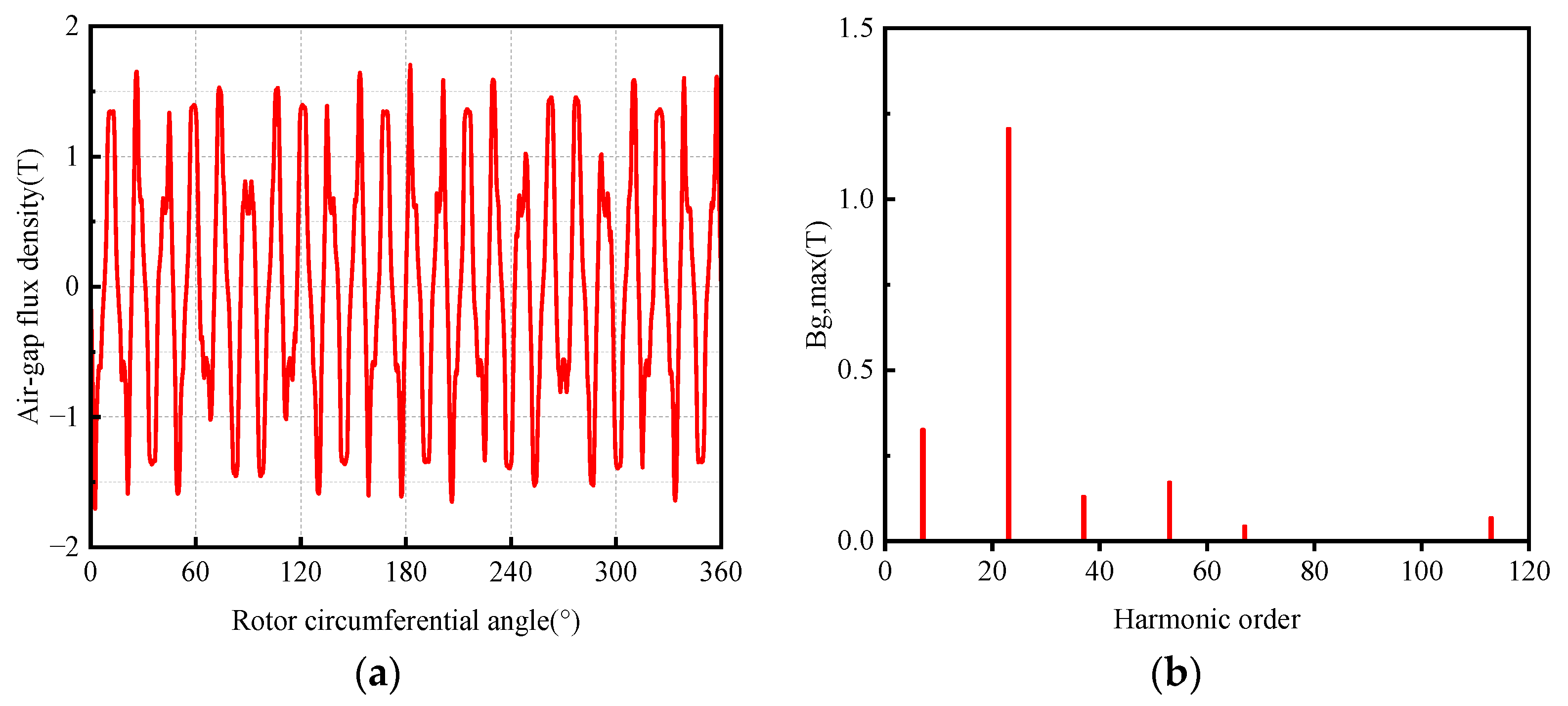
The air-gap flux density of the machine reflects its magnetic flux exchange efficiency. As shown in Figure 8a, the air-gap flux density waveform contains 23 small peaks and 23 small valleys, indicating that the outer rotor of the machine has 23 pole pairs. Overall, the waveform exhibits seven large peaks and seven large valleys, corresponding to the seven-pole-pair winding design of the machine. This further verifies the magnetic field modulation principle of vernier machines from another perspective.
Due to the leakage flux and losses at the stator tooth tips, the peak air-gap flux density of the machine is 1.78 T. Fourier decomposition of the air-gap flux density was performed, and the results are shown in Figure 8b. The 23rd-order air-gap flux density has the largest amplitude, which is consistent with the outer rotor pole pair number of the FM-PMVG. The seventh-order air-gap flux density has the second largest amplitude, matching the winding pole pair number of the FM-PMVG. The other prominent harmonic components are all magnetic field modulation components.

3.2. Flux Linkage and Induced Electromotive Force

The proposed FM-PMVG generator has 30 stator slots, corresponding to 30 distributed windings. For a three-phase machine, ten coils are connected in series to form a single-phase winding. Therefore, the flux linkage of each phase winding is the sum of the flux linkages of the ten coils in that phase.
The flux linkage expression of phase A winding is given by
ψ A = ψ A 1 + ψ A 2 + ψ A 3 + ψ A 4 + ψ A 5 + ψ A 6 + ψ A 7 + ψ A 8 + ψ A 9 + ψ A 10
where ψ A   denotes the flux linkage of phase A winding, and ψ A 1 to ψ A 10 represent the flux linkages of coils A1 to A10, respectively. According to electromagnetic theory, the flux linkage expressions of the three-phase windings of the machine are as follows:
ψ A = ψ 0 c o s θ 0 ψ B = ψ 0 c o s θ 0 2 π 3 ψ C = ψ 0 c o s θ 0 + 2 π 3
where ψ A , ψ B , and ψ C are the flux linkages of phase A, B, and C windings, respectively; ψ 0 is the amplitude of the winding flux linkage; Pw is the number of winding pole pairs; and θ 0 is the rotor position angle.
According to Faraday’s law of electromagnetic induction, the no-load induced electromotive force (EMF) of the three-phase windings is given by
e = d ψ d t
Accordingly, the no-load induced EMFs of the three-phase windings are derived as
e A = d ψ A d t = e m c o s θ 0 e B = d ψ B d t = e m c o s θ 0 2 π 3 e C = d ψ C d t = e m c o s θ 0 + 2 π 3
where e A , e B , e C are the no-load induced EMFs of phase A, B, and C, respectively, and e m is the amplitude of the no-load induced EMF.
The sinusoidality of the back-EMF can be quantified by THD based on its harmonic spectrum. The expression of THD is as follows:
THD ( % ) = i = 2 n U i 2 U 1 × 100 %
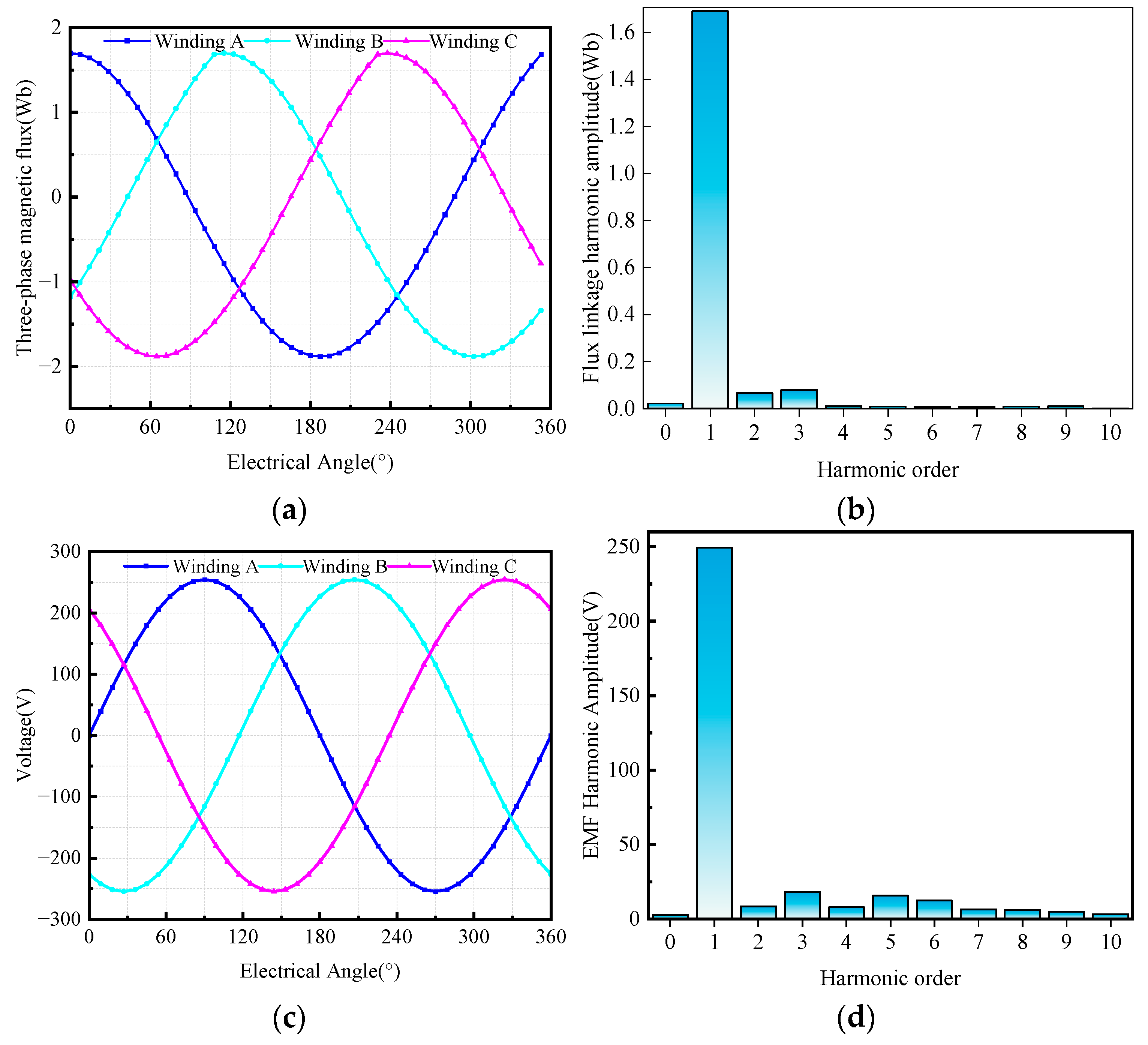
A no-load condition simulation of the FM-PMVG machine is performed using the ANSYS transient field solver at a rotational speed of 65 rpm. The transient responses of the winding flux linkage and no-load induced EMF are obtained by analyzing the electromagnetic characteristics over one complete electrical cycle of the rotor. As shown in Figure 9a,b, the three-phase winding flux linkages exhibit a standard three-phase sinusoidal distribution, and the THD is calculated to be 2.9%. Figure 9c further confirms that the winding induced EMF also has excellent three-phase sinusoidal waveform characteristics, with a peak value of 270 V. Harmonic analysis of the no-load induced EMF is conducted using the Fourier decomposition method, as presented in Figure 9d. Based on Equation (34), the THD of the no-load induced EMF is calculated to be only 3.7%. This index is significantly better than the specified limit of 5%, verifying the superior electromagnetic performance of the proposed machine design.

3.3. Cogging Torque

Cogging torque is an inherent issue in FM-PMVG. It arises from the alternating alignment between slots and rotor PMs as the rotor rotates, leading to continuous changes in their relative positions. From the perspective of the energy method, variations in the machine’s magnetic permeance cause changes in the magnetic field energy, which in turn generate cogging torque.
For FM-PMVGs, each stator tooth passing over a pair of rotor PMs induces a periodic fluctuation in the magnetic field energy. Cogging torque constitutes the main component of the machine’s starting resistance torque. Excessive cogging torque will lead to periodic torque ripple, noise, and vibration during generator operation; increase mechanical losses during rotation; shorten the service life and maintenance interval of the machine; and hinder the improvement in its efficiency.
The cogging torque period of conventional PMVG can be calculated by the following formula [19]:
T c o g = P r 360 ° L C M Z , 2 p r
where T c o g is the cogging torque period, Z is the number of stator teeth, and L C M Z , 2 p r denotes the least common multiple of Z and 2 p r .
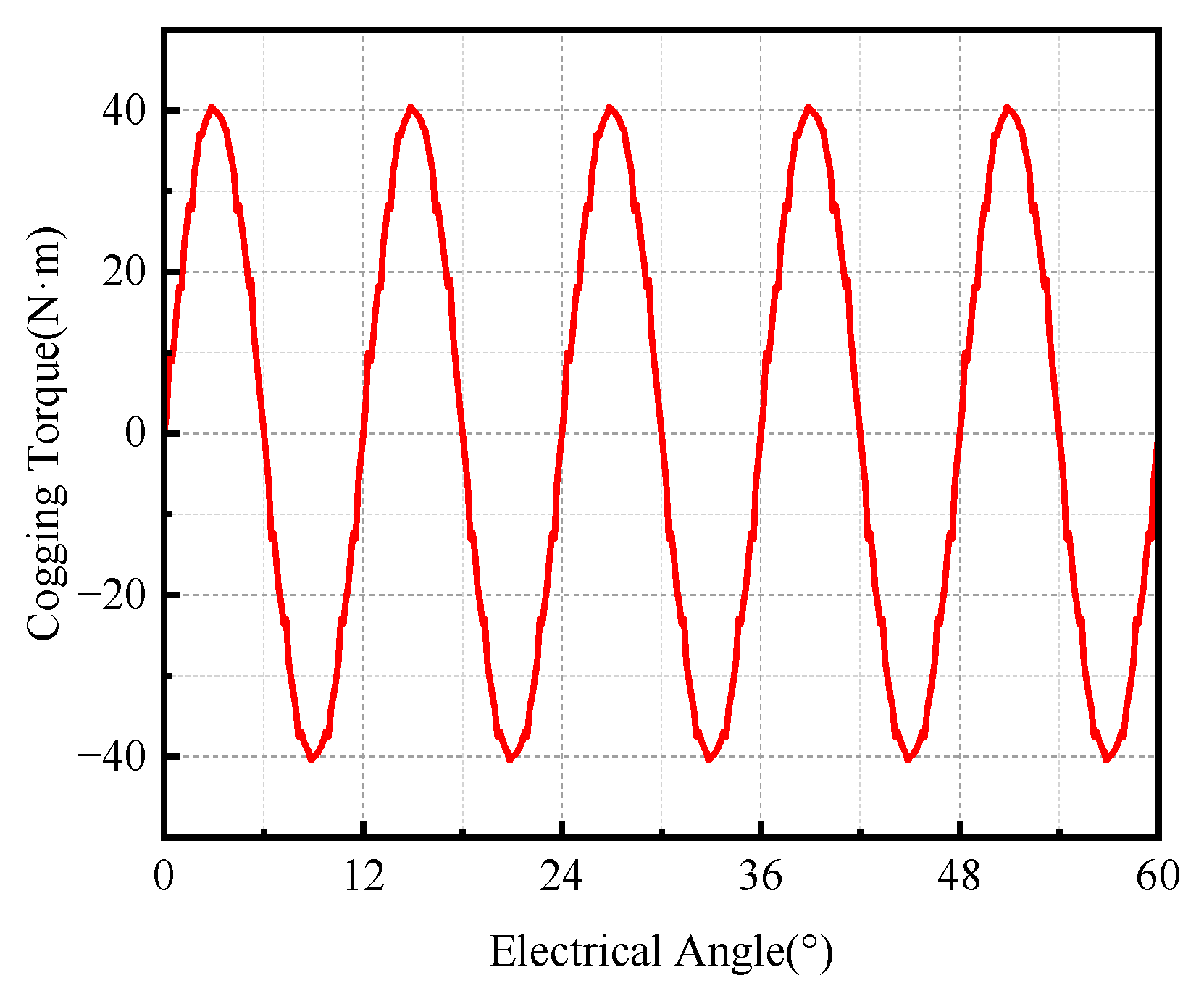
Substituting Z = 30 and P r = 23 into Equation (35), the electrical period of the cogging torque for the FM-PMVG is calculated to be 12°. To save simulation time and improve computational efficiency, five electrical periods of cogging torque are selected for simulation demonstration. Within a 60° electrical angle range, 300 rotor position points are sampled to record the cogging torque and generate the corresponding curve, resulting in the cogging torque simulation plot shown in Figure 10.
As can be seen in the cogging torque curve, the torque waveform exhibits five distinct cycles within 60 electrical degrees. The peak value of the cogging torque is approximately 42 N·m, which has a negligible impact on the machine’s performance.

3.4. Demagnetization Risk Assessment

For FM-PMVG, PM serve as the only excitation source. Irreversible demagnetization is a critical bottleneck limiting the reliable operation of generators under low-speed direct-drive conditions. Assessing this risk can effectively validate the rationality of the machine’s electromagnetic design, identify influencing factors, and optimize the machine design and protection strategies.
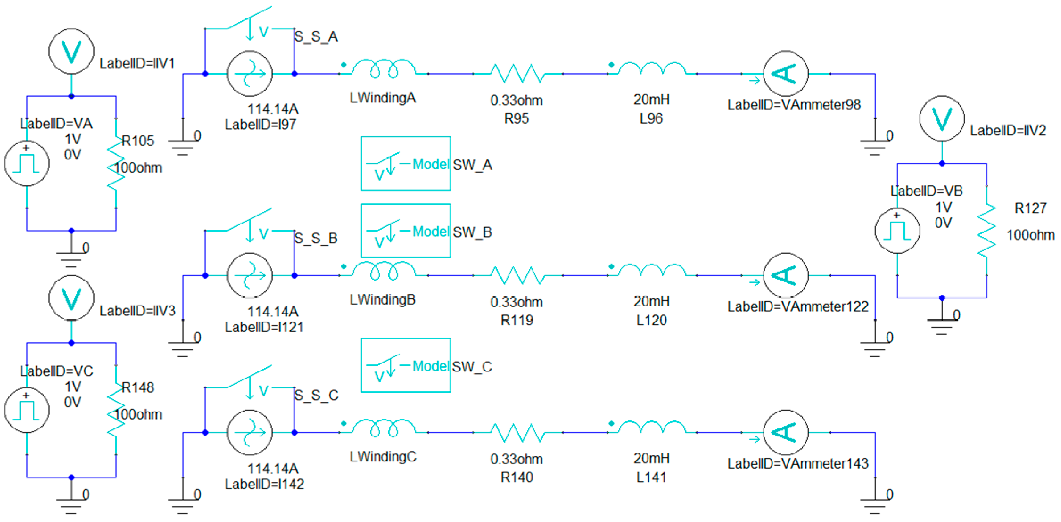
The common demagnetization risks of PMs include two scenarios: uncontrolled temperature rise under transient conditions and excessive local temperature rise caused by concentrated eddy current losses in the machine. The short-circuit circuits are built in the ANSYS Simplorer module, as shown in Figure 11. The machine excitation is switched to the external circuit mode to verify the maximum short-circuit peak current of the generator.
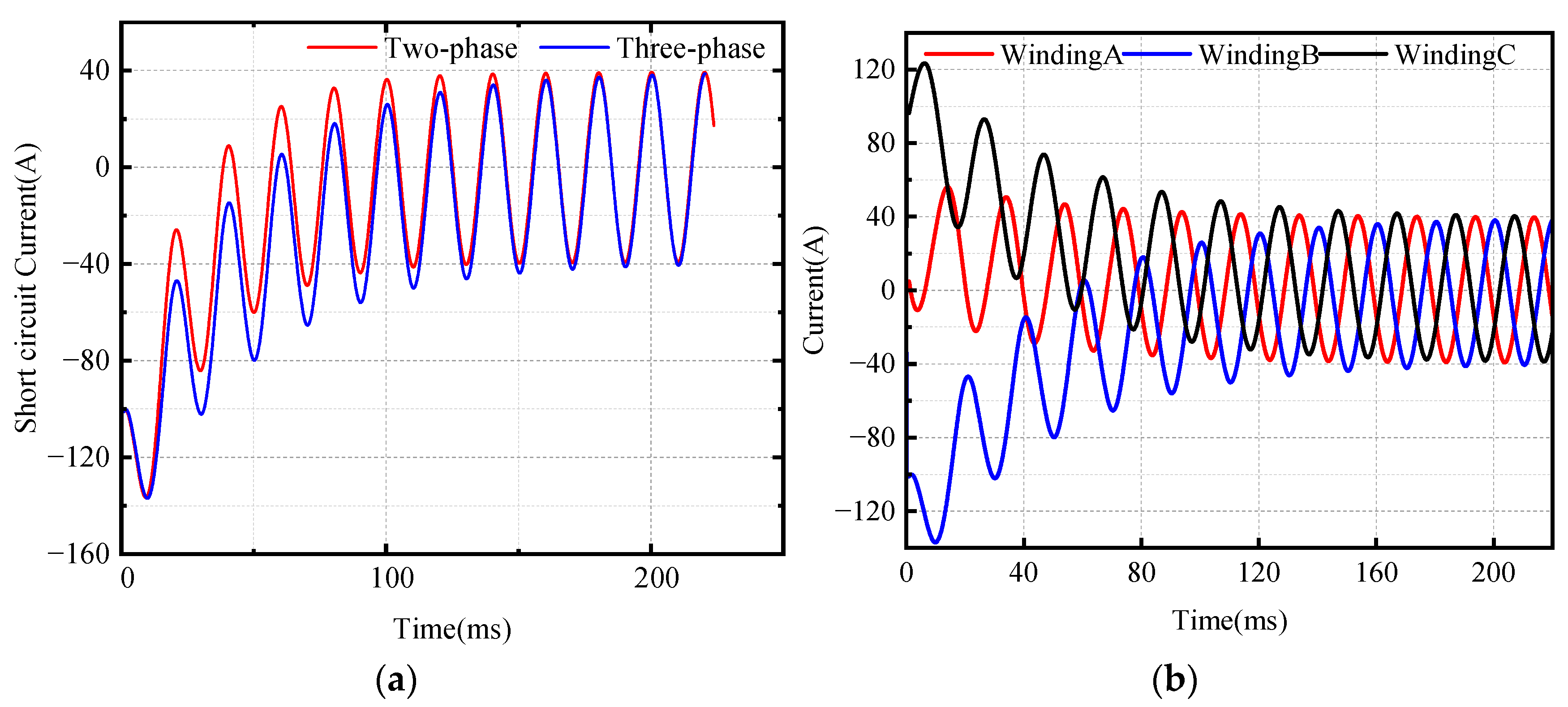
After determining the short-circuit peak current, a current input function is set with a peak value slightly higher than the machine’s short-circuit peak current, which is set to 137 A. The demagnetization risk of the machine is verified by analyzing the magnetic flux density distribution, confirming the rationality of the machine design. As can be seen in Figure 12a, the three-phase short-circuit has a higher peak current than the two-phase short-circuit. Therefore, the three-phase short-circuit current of the generator is investigated, and the results are shown in Figure 12b. It can be seen that the short-circuit current of phase B reaches a peak value of 136.6 A at 2.4 ms.
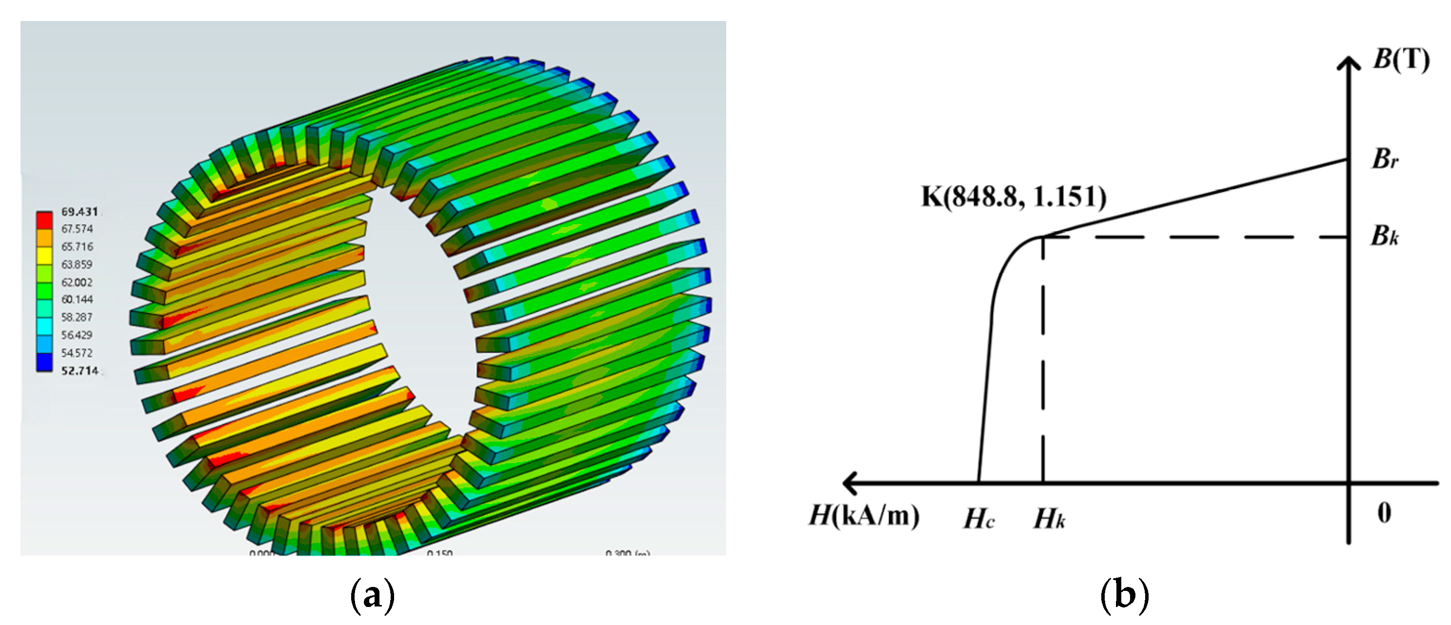
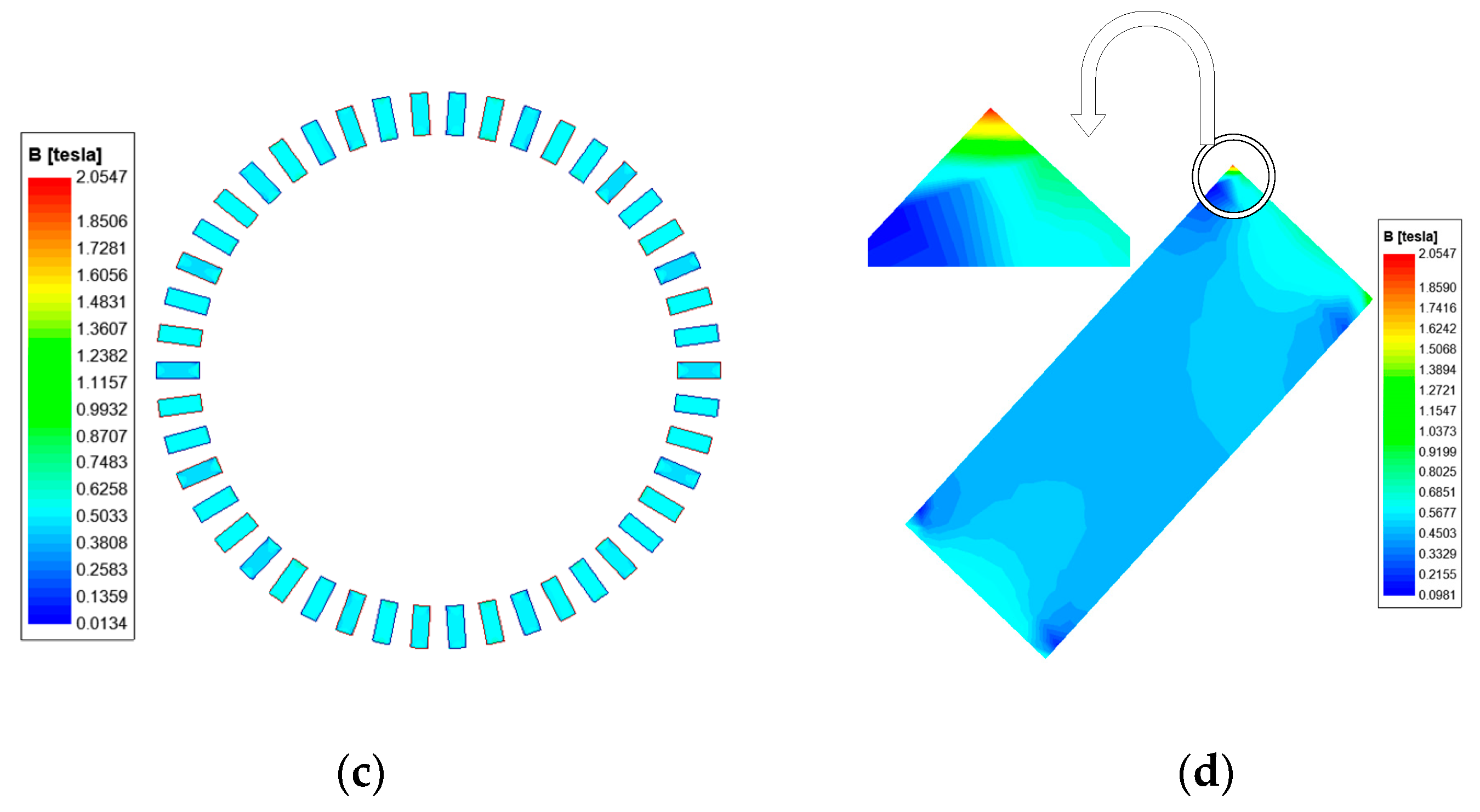
The spatial temperature distribution of the permanent magnets at the peak short-circuit current instant is illustrated in Figure 13a, with a measured maximum temperature of 70 °C. For demagnetization risk evaluation, Figure 13b further provides the demagnetization curve of the N40SH sintered neodymium–iron–boron (NdFeB) permanent magnet at 100 °C.The magnetic field strength distribution of the PMs at the current peak point is shown in Figure 13c,d. The magnetic field strength of the PMs in this machine is still lower than their intrinsic coercivity, and the area with high magnetic field strength accounts for far less than 1% of the total PM area. This proves that there is no demagnetization risk for the PMs of the proposed machine.

4. Generating Condition Analysis

4.1. Output Voltage and Current Analysis

Taking a single unit as the output source, the power generation condition of the FM-PMVG machine was investigated via field-circuit coupled simulation using the ANSYS Maxwell and Simplorer modules, combined with the actual operating conditions of the machine.
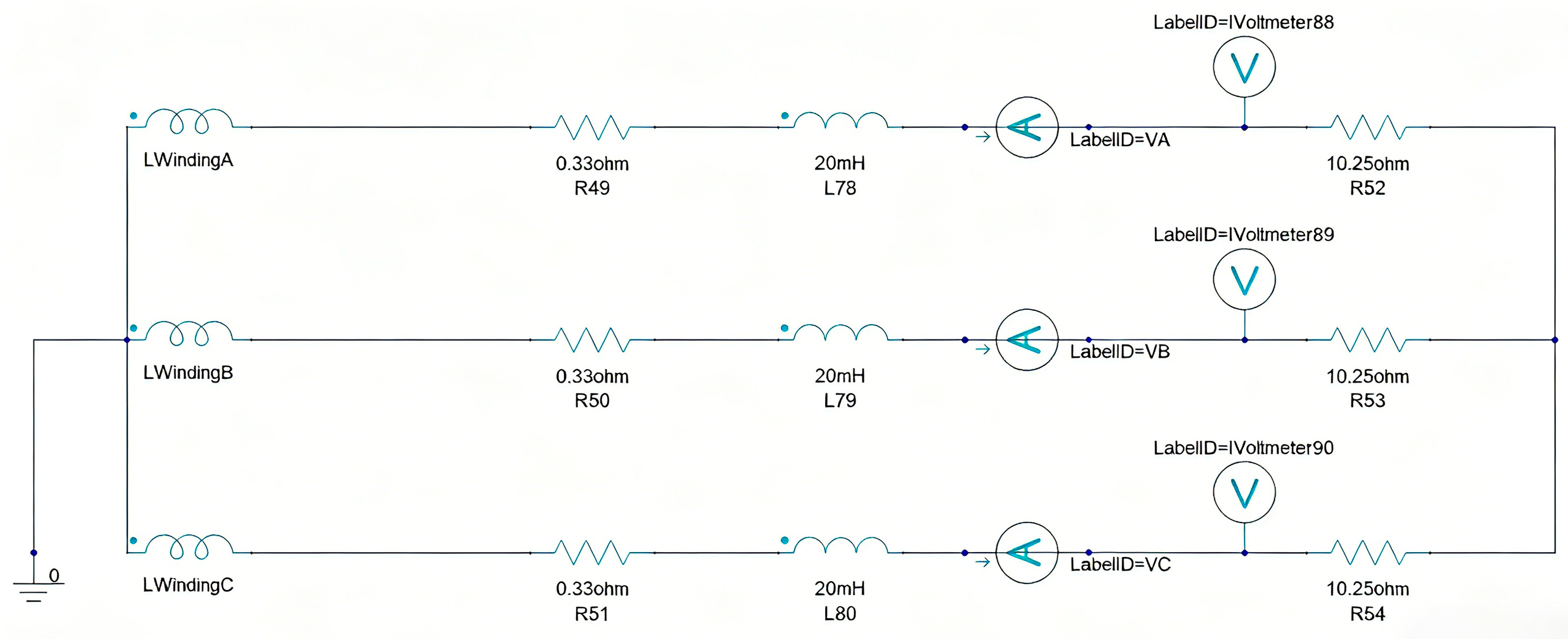
In the practical application scenario of this FM-PMVG, the driven loads mostly consist of resistive and inductive components. As shown in Figure 14, a three-phase symmetrical resistance-inductance circuit is configured in Simplorer. Considering the internal resistance and self-inductance of the machine, in addition to the three-phase windings, an internal resistance of 1 Ω and a self-inductance coil of 20 mH are connected in series, and an external load of 10.25 Ω resistance is applied to analyze the external characteristics of the machine.
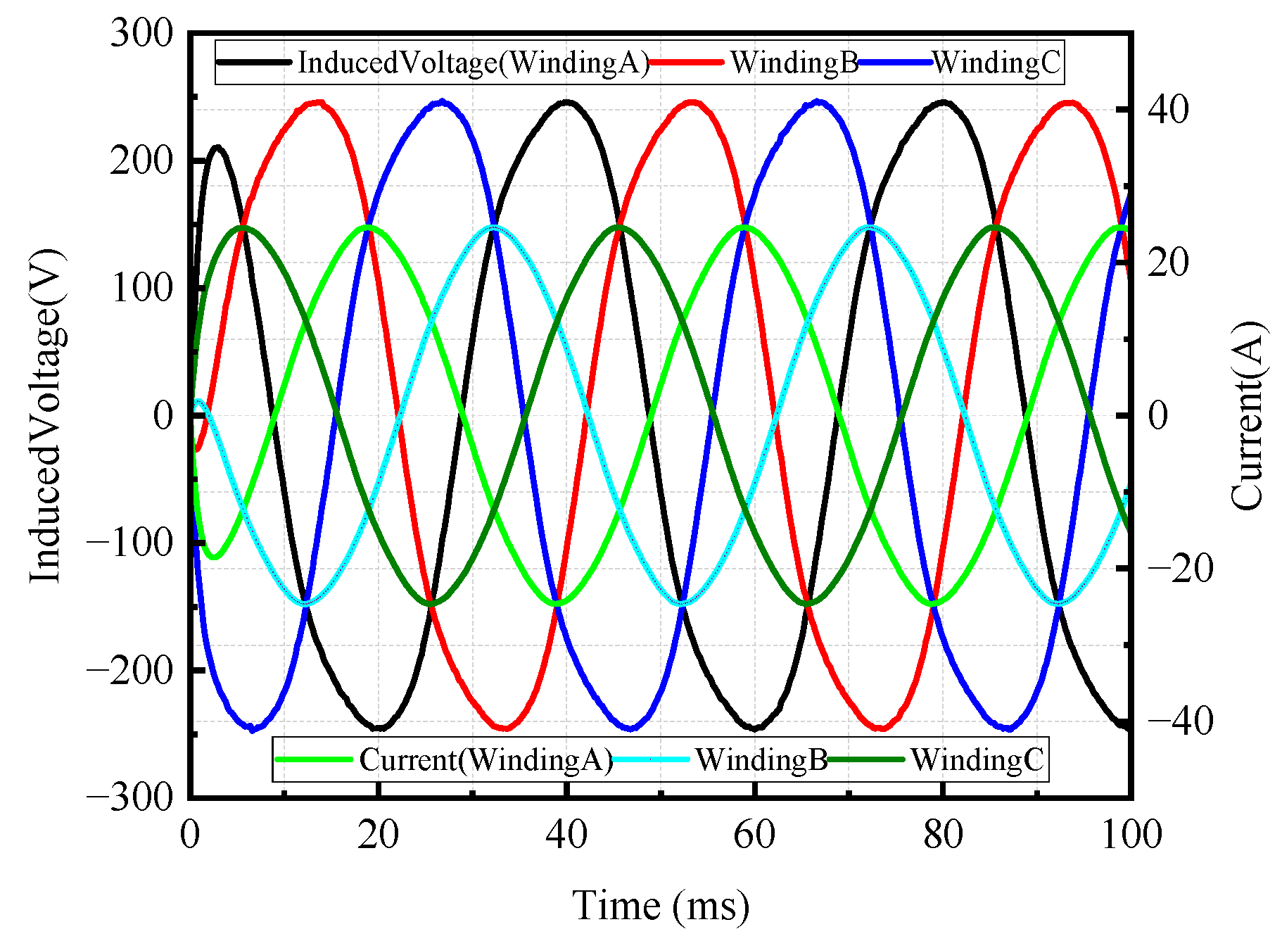
After loading the external circuit into the simulation program, the simulation calculation was performed, as shown in Figure 15. When the FM-PMVG operates at the rated speed of 65 rpm, the load voltage amplitude is 245.46 V, and the load current amplitude is 24.69 A.
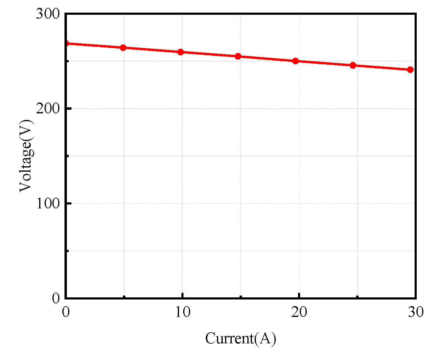
By varying the external load resistance values, the output terminal voltage and current of the machine were measured, and the voltage–current relationship of the machine is shown in Figure 15. The analysis shows that its voltage regulation is 9.18%, which verifies the excellent output characteristics of the proposed machine.
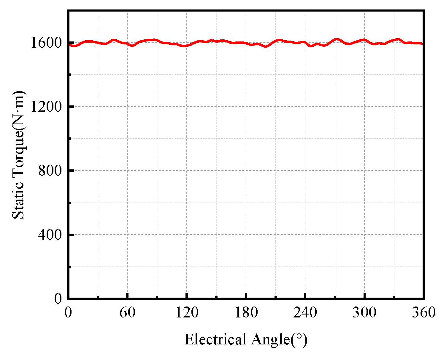
The input torque obtained from the Maxwell–Simplorer field-circuit coupled simulation is shown in Figure 16, with an average value of 1600 N·m after stabilization.
According to the calculation formula of input power P I N ,
P I N = T 2 π n 60
where n is the rotational speed of the machine, and T is the input torque of the machine. The calculated input power is 10.882 kW.
The output power of the machine in the simulation is 10 kW, and the input power is 10.88 kW. The calculation formula of generator efficiency η is given by
η = P o u t P I N × 100 %
Based on Equation (37), the generator efficiency in the simulation is calculated to be 92%. However, this value is not accurate, because the effects of the time step setting in ANSYS Maxwell and external environmental factors on machine parameters are not considered in the simulation. Therefore, the losses of the generator need to be calculated separately using relevant parameters and empirical formulas when evaluating the machine efficiency. The loss calculation of the machine is presented as follows.

4.2. Loss and Efficiency Analysis

The Maxwell–Simplorer field–circuit coupled simulation only considers the ideal state of the FM-PMVG generator. However, in actual operation, the machine losses will increase. For example, the eddy current loss is idealized in the simulation. Meanwhile, the simulation accuracy is affected by the mesh generation process. In practical operation, external environmental factors such as temperature, humidity, and electromagnetic interference will also affect the generator’s efficiency.
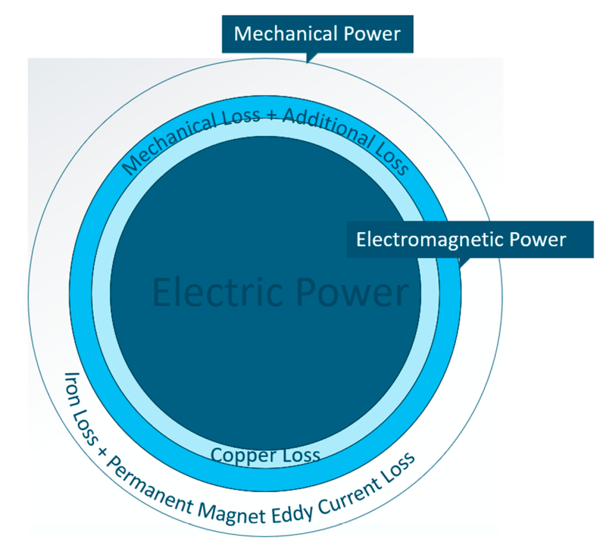
Therefore, the efficiency obtained directly from the coupled simulation is inaccurate. As shown in Figure 17, in practical applications, the generator losses include not only iron loss and PM eddy current loss, but also mechanical loss, stray loss, and copper loss. These losses act as hidden heat sources during machine operation, causing temperature rise and increasing the demagnetization risk of permanent magnets.

4.2.1. Copper Loss

Copper loss arises from the inherent resistance and inductance of the copper windings. For calculation convenience, only the effect of resistance on machine efficiency is considered. The power calculation formula of copper loss is given by
P c u = m I 2 2 R
where m is the number of phases of the generator, I is the peak value of phase current, and R is the resistance of a single-phase copper winding.
The resistance of the copper winding can be simplified as
R = ρ l S
where ρ is the resistivity of copper, l is the total length of all conductors in a single phase, and S is the cross-sectional area of the copper wire.
By inputting the relevant parameters into the Maxwell calculator, the designed internal resistance of the machine is obtained as 0.34 Ω. As shown in Figure 18, combined with the current amplitude of 24.69 A under the simulation output condition, the copper loss of the machine is calculated to be 304.80 W.

4.2.2. Iron Loss

Iron loss in electrical machines arises from the time-varying main magnetic field in the iron core, which consists of eddy current loss and hysteresis loss. For generator applications, the expression for calculating the stator and rotor iron losses of the machine is [20]:
P F e = P h + P c P h = k h f B m α P c = k c f 2 B m 2 + k a f 1.5 B m 1.5
where P F e , P h , and P c   are the total iron loss, hysteresis loss, and eddy current loss of the machine, respectively; f is the alternating frequency of the magnetic field; k h , k c and k a are the hysteresis loss coefficient, normal eddy current loss coefficient, and anomalous eddy current loss coefficient, respectively; B m is the amplitude of the magnetic flux density; and α is a constant coefficient.
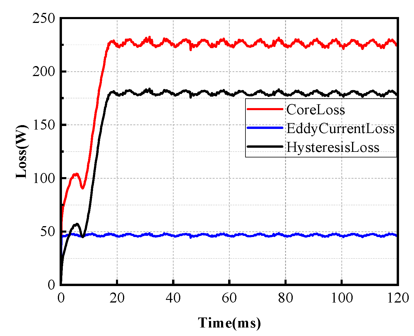
In ANSYS Maxwell, the iron loss analysis of the machine under power-generation condition is shown in Figure 19. It can be seen that the iron loss of the machine is 232.46 W.

4.2.3. PM Eddy Current Loss

PM eddy current loss PPM is caused by the eddy currents induced in the permanent magnets due to the alternating internal magnetic flux. The PM eddy current loss can be calculated by the following formula:
P P M = L a V P M L b 2 k P M 2 f 2 B P M m 2 12 ρ P M L a + L b
where L a , L b , and V P M are the axial length, tangential length, and volume of the permanent magnet, respectively; k P M is the electromotive force proportional coefficient; B P M m is the peak value of the alternating component of the PM flux density; and ρ P M is the resistivity of the permanent magnet.
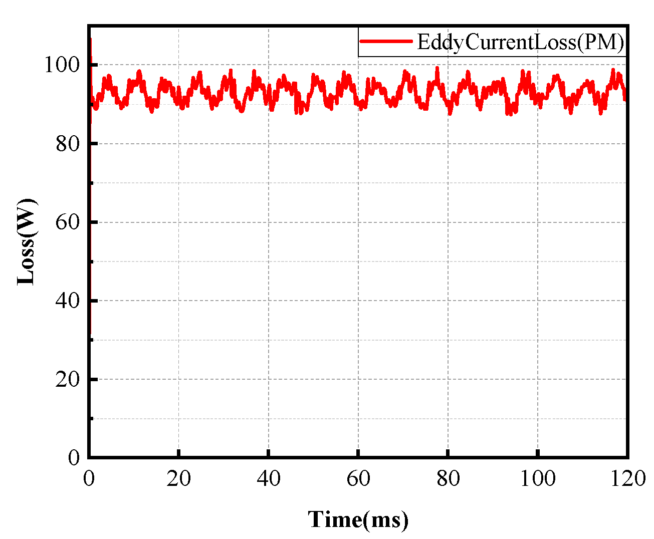
The PM eddy current loss under power generation condition obtained by simulation is shown in Figure 20, with an average value of 96.32 W.

4.2.4. Stray Loss

The stray loss pad is an inevitable component in electrical machines. It is mainly caused by the interaction forces between mechanical structures, torque ripple, and leakage flux losses of the machine. However, it is difficult to calculate stray loss accurately, as it involves multiple influencing factors. Through efficiency analysis and testing of various machines, a relatively reliable empirical formula has been established. Since stray loss accounts for a small proportion of the total machine loss and has a minor impact on the results, it is usually taken as 1~2% of the rated power of the machine [21].
The various losses of the FM-PMVG under power generation condition are summarized in Table 3.
The power generation efficiency of the FM-PMVG is expressed as
η = P o u t P I N × 100 % = P o u t P o u t + P c u + P P M + P F e + P a d × 100 %
According to the above formula, the efficiency of the FM-PMVG under rated conditions is calculated to be 92.73%.

4.2.5. Comparative Analysis

Furthermore, to quantitatively evaluate the competitive advantages of the proposed FM-PMVG, a comprehensive performance benchmarking against representative PMVGs reported in the literature is summarized in Table 4.
Among all compared topologies, the proposed FM-PMVG achieves the highest rated power of 10 kW. The PMVG presented in [8] exhibits the lowest THD, while the design reported in [22] delivers the highest efficiency of 94.8%. Most importantly, the proposed generator achieves the highest volumetric power density of 387.5 kW/m3 among all compared designs, demonstrating its significant superiority in lightweight design for low-speed direct-drive applications. The rotational speed of the proposed FM-PMVG is substantially lower than that of the other two benchmark machines, making it more suitable for low-speed direct-drive power supply applications. This inherent advantage is a direct manifestation of the speed amplification effect embedded in the magnetic field modulation principle.

5. Experimental Verification

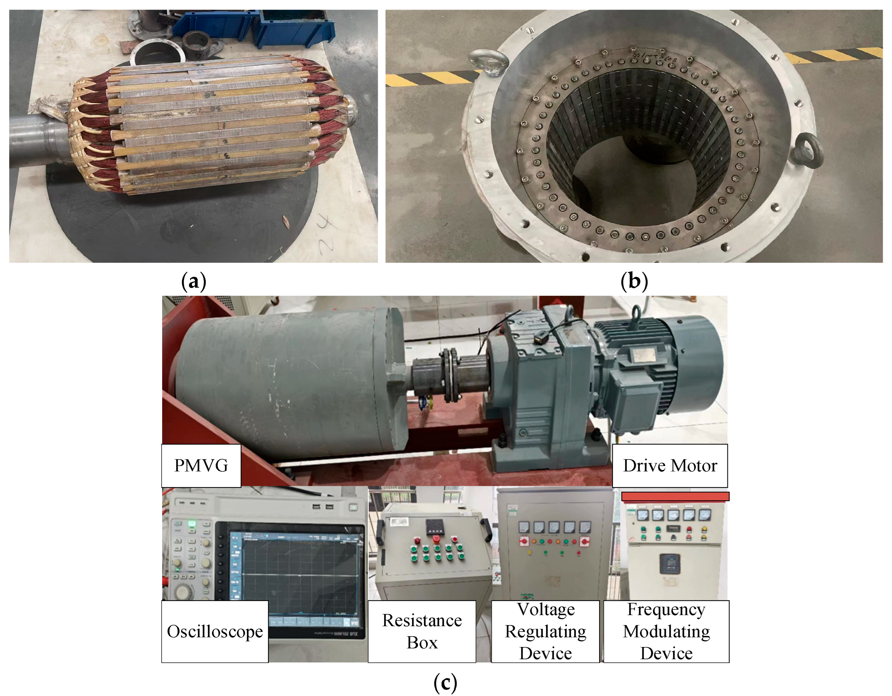
To verify the correctness of the above theoretical analysis and simulation results, a prototype with a rated speed of 65 r/min, a rated power of 10 kW, and an output voltage of 270 V was designed and manufactured. Figure 21 shows the physical photos of the prototype and the related power equipment used in the experiment. The no-load voltage test of the prototype at different speeds was carried out by adjusting the frequency converter to control the speed of the driving motor. At the initial stage of the test, the induced electromotive force of the machine during no-load operation was recorded.
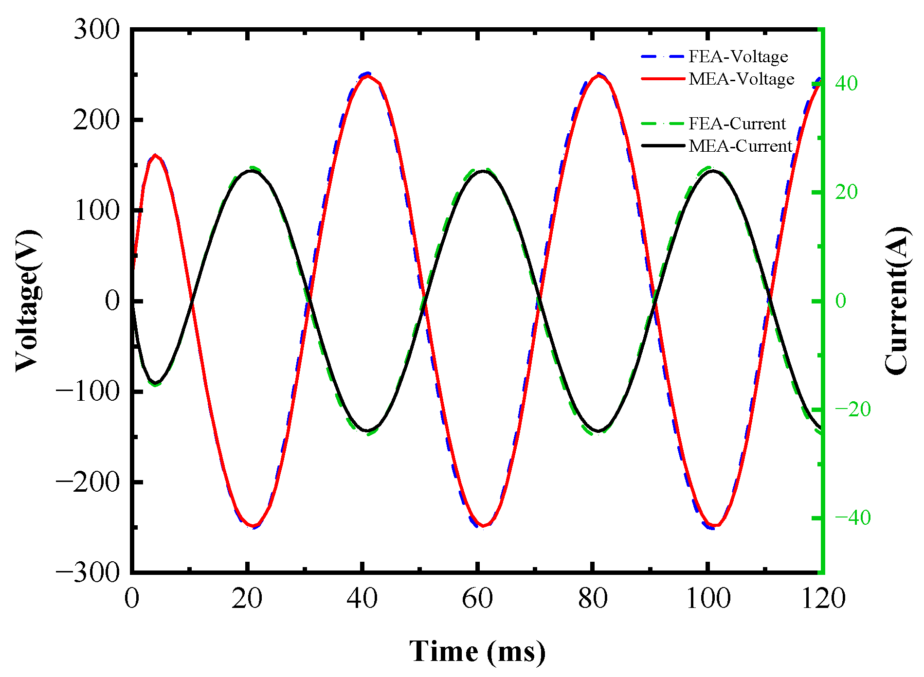
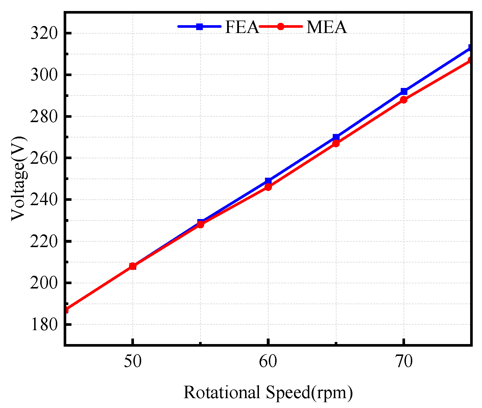
The output terminal voltage and current of the machine were measured under the rated load of 10 kW and compared with the simulation results. The comparison of the voltage and current of the machine is shown in Figure 22. The simulation measured voltage peak is 245.95 V, and the current peak is 24.62 A, while the experimental measured voltage peak is 243.0 V, and the current peak is 24.34 A. The error of the output voltage value under rated conditions is 1.2%, and the error of the current value is 1.0%, both of which are within the standard range and meet the design requirements.
The variation of the no-load induced electromotive force of the machine with the rotor speed is shown in Figure 23. The permanent magnet flux linkages of the prototype are calculated to be 4.2 Wb and 3.96 Wb, respectively, and the calculated discrepancy is as low as 5.7%, which confirms the validity and accuracy of the developed FEA model. The primary source of the observed discrepancies lies in the inherent idealizations of the 2D FEA model. Specifically, the 2D simulation does not account for end-winding leakage flux, winding skin effect, and proximity effect, nor does it incorporate the temperature rise of motor components during operation.
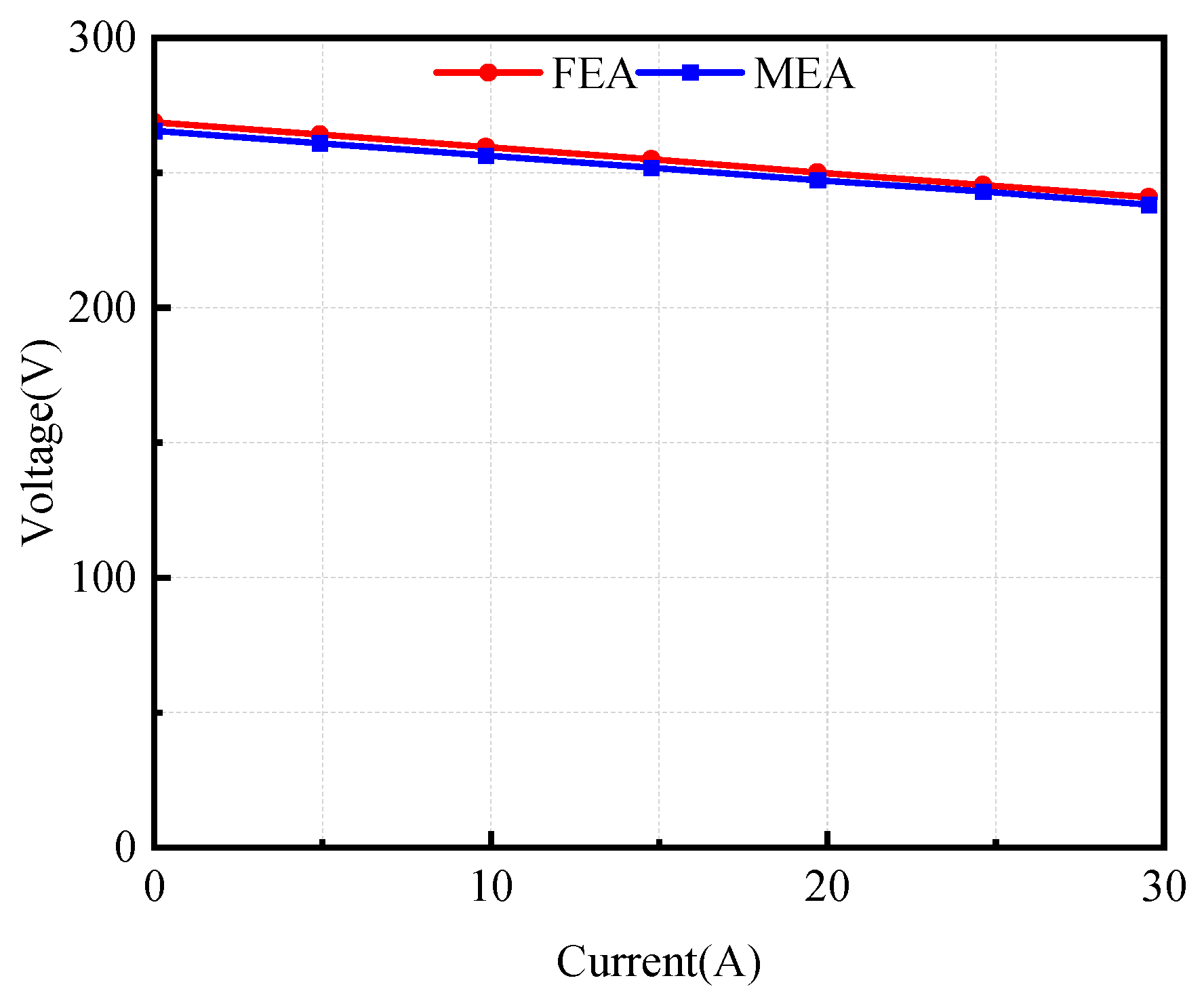
By connecting different loads to the output terminal of the generator, the output voltage and current of the generator are measured, and the voltage–current curve is plotted as shown in Figure 24 to determine the external characteristic curve of the machine. When the machine reaches the rated condition with a current of 24.62 A, the output voltage of the machine is 243.00 V, and the voltage regulation of the machine is 9.26%, which overcomes the inherent high-voltage-regulation issue of magnetic field modulation machines.
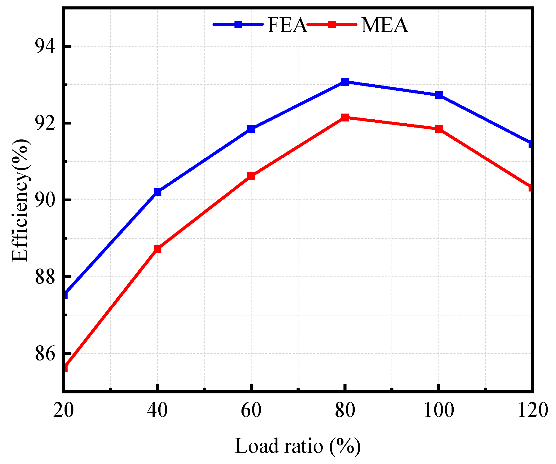
The efficiency at different load factors under the rated speed was analyzed, and the results are shown in Figure 25. The variation trend of efficiency with the load factor is completely consistent with the simulation results. The highest efficiency occurs near a 75% load factor, and the efficiency decreases rapidly under overload conditions, which verifies the previous conclusion that copper loss is the core factor limiting the overload capability.
It can be seen in the comparison results that the absolute error between the simulated and experimental efficiency is less than 1.2%, indicating good consistency. The experimental efficiency is slightly lower than the simulated efficiency, mainly because the 2D simulation model ignores the additional copper loss at the winding ends and the eddy current loss in structural components caused by end leakage flux.
In this study, a 2D FEA model is employed for electromagnetic simulations, which inherently neglects the end effects and axial leakage flux. For the outer-rotor Spoke-array configuration, end-winding leakage flux accounts for 8–10% of the total leakage flux [18], which results in a 1.2% overestimation of the back-EMF amplitude compared with experimental measurements. Similarly, axial leakage flux leads to a 1.2% overprediction of the motor efficiency. These values are in excellent agreement with the experimentally observed 1.2% voltage discrepancy and 1.0% current discrepancy, thus quantitatively validating the accuracy of the developed simulation model.

6. Conclusions

In this paper, a 10 kW outer-rotor spoke-array FM-PMVG for low-speed direct-drive applications is proposed, analyzed, and prototyped. The validity of the theoretical analysis and 2D FEA was verified by experimental tests on the prototype. From the analysis, simulations, and experimental results, the following conclusions can be drawn:
  • The spoke-array permanent magnet topology effectively suppresses leakage flux and enhances air-gap flux density, significantly improving the volumetric power density.
  • The outer-rotor field-modulated structure enables effective magnetic field modulation, improving space utilization and torque capability at low speeds.
  • The proposed generator exhibits excellent no-load performance with a low back-EMF THD of 3.7%, ensuring high-quality output voltage.
  • The developed FM-PMVG achieves high efficiency and low cogging torque, making it suitable for low-speed, direct-drive renewable energy applications.
Future work will focus on comprehensive thermal field analysis, multi-objective optimization, and multi-physics coupling simulation to further enhance the machine’s performance.

Author Contributions

Conceptualization, K.W.; methodology, B.W.; software, M.Q.; validation, K.W., B.W. and S.C.; formal analysis, K.W.; investigation, M.Q.; resources, K.W.; data curation, K.W.; writing—original draft preparation, K.W.; writing—review and editing, K.W.; visualization, K.W.; supervision, M.Q.; project administration, M.Q. All authors have read and agreed to the published version of the manuscript.

Funding

This research received no external funding.

Data Availability Statement

The data presented in this study are available upon request from the corresponding author to preserve privacy.

Conflicts of Interest

The authors declare no conflicts of interest.

References

  1. Shrivastava, N.; Sashidhar, S.; Subudhi, B. A Novel Dual Armature with Dual Halbach Array Based Tubular Linear Vernier Generator for Wave Energy Conversion. In Proceedings of the 2025 IEEE Energy Conversion Congress & Exposition Asia (ECCE-Asia), Bengaluru, India, 11–14 May 2025; pp. 1–6. [Google Scholar]
  2. Kim, D.-H.; Kim, K.S.; Yang, I.-J.; Lee, J.; Kim, W.-H. Alternative Bridge Spoke Permanent Magnet Synchronous Generator Design for Wind Power Generation Systems. IEEE Access 2021, 9, 152819–152828. [Google Scholar] [CrossRef]
  3. Ghods, M.; Faiz, J.; Bazrafshan, M.A.; Arianborna, M.H. A Mesh Design Technique for Double Stator Linear PM Vernier Machine Based on Equivalent Magnetic Network Modeling. IEEE Trans. Energy Convers. 2022, 37, 1087–1095. [Google Scholar] [CrossRef]
  4. Faiz, J.; Haghvirdiloo, S.; Ghaffarpour, A. Different types of electrical generators for converting wave energy into electrical energy–A review. J. Mar. Sci. Appl. 2025, 24, 76–97. [Google Scholar] [CrossRef]
  5. Arish, N.; Teymoori, V.; Dube, L.; Kamper, M.J.; Wang, R.-J. Comparative Analysis of PM and Non-PM Design Options for Small-Scale Wind Generators. In Proceedings of the 2024 32nd Southern African Universities Power Engineering Conference (SAUPEC), Stellenbosch, South Africa, 24–25 January 2024; pp. 1–6. [Google Scholar]
  6. Wu, L.; Qu, R. A Novel Dual-Stator Vernier Permanent Magnet Machine with Improved Power Factor. IEEE Trans. Ind. Appl. 2022, 58, 3486–3496. [Google Scholar] [CrossRef]
  7. Liang, Y.; Song, Z.; Ma, Y.; Lang, X. A Novel Efficient and High-Capacity Permanent Magnet Vernier Machine for Urban Intelligent Wind Power Systems. In Proceedings of the 2024 27th International Conference on Electrical Machines and Systems (ICEMS), Fukuoka, Japan, 26–29 November 2024; pp. 1034–1040. [Google Scholar]
  8. Sharma, P.; Gowtham, V.; Sashidhar, S. Magnetic Gear-Based Ferrite PM Vernier Generator for a Direct-Drive Wind Turbine. IEEE Trans. Ind. Electron. 2026, 73, 1793–1803. [Google Scholar] [CrossRef]
  9. Wang, R.; Wang, B.; Tian, D.; Cai, H.; Cheng, M.; Hua, W. Slot-Pole Combination Analysis of FSCW-PMVM on Magnetic Field Modulation Performance. IEEE Trans. Transp. Electrif. 2025, 11, 5665–5675. [Google Scholar] [CrossRef]
  10. Jung, W.-S.; Shin, H.-S.; Kim, S.-M.; Kwalk, K.-W.; Kim, K.-H.; Park, J.-Y.; Shin, K.-H.; Choi, J.-Y. Analytical Calculation and Measurements of the Magnetic Force Between Permanent Magnet and Rotor Yoke of Large-Scale Permanent Magnet Synchronous Generator. IEEE Trans. Magn. 2025, 61, 8100204. [Google Scholar] [CrossRef]
  11. Tao, X.; Yiguang, C.; Haotian, S.; Ning, X.; Weijie, H. Design and Analysis of Fractional Pole-Pair Permanent Magnet Vernier Machine Using Asymmetrical V-Shaped Permanent Magnet. In Proceedings of the 2023 26th International Conference on Electrical Machines and Systems (ICEMS), Zhuhai, China, 5–8 November 2023; pp. 2529–2533. [Google Scholar]
  12. Xiang, Z.; Peng, L.; Zhu, X.; Wei, J.; Yue, Z. Research on Power Factor Improvement of a PM Vernier In-Wheel Motor with Collaborative Design of PM and Armature Flux Linkage. CES Trans. Electr. Mach. Syst. 2026, 10, 44–54. [Google Scholar] [CrossRef]
  13. Ghods, M.; Gorginpour, H.; Bazrafshan, M.A.; Toulabi, M.S. Equivalent Magnetic Network Modeling of Dual-Winding Outer-Rotor Vernier Permanent Magnet Machine Considering Pentagonal Meshing in the Air-Gap. IEEE Trans. Ind. Electron. 2022, 69, 12587–12599. [Google Scholar] [CrossRef]
  14. Tao, X.; Yiguang, C.; Haotian, S. A Multi-Objective Optimization Design Method of Surface Mounted Vernier Permanent Magnet Motor Based on Theoretical Analysis Model. In Proceedings of the 2023 26th International Conference on Electrical Machines and Systems (ICEMS), Zhuhai, China, 5–8 November 2023; pp. 191–196. [Google Scholar]
  15. Mi, W.; Cai, Z.; Lee, H.; Luo, Y.; Zhang, C.; Zhao, H.; Yu, J. Loss and Thermal Analysis Considering Stator Phase Shift Effect in Dual-Stator Spoke-Array Permanent Magnet Vernier Machines. In Proceedings of the 2025 IEEE 8th International Electrical and Energy Conference (CIEEC), Changsha, China, 16–18 May 2025; pp. 2750–2755. [Google Scholar]
  16. Dong, Z.; Jiang, M.; Niu, S.; Chau, K.T. Overview of Permanent Magnet Wind Power Generators. IEEE Trans. Magn. 2025, 61, 8102011. [Google Scholar] [CrossRef]
  17. Kana Padinharu, D.K.; Li, G.J.; Zhu, Z.Q.; Foster, M.P.; Stone, D.A.; Griffo, A.; Clark, R.; Thomas, A. Scaling Effect on Electromagnetic Performance of Surface-Mounted Permanent-Magnet Vernier Machine. IEEE Trans. Magn. 2020, 56, 8100715. [Google Scholar] [CrossRef]
  18. Li, X.; Chau, K.T.; Cheng, M. Comparative Analysis and Experimental Verification of an Effective Permanent-Magnet Vernier Machine. IEEE Trans. Magn. 2015, 51, 8203009. [Google Scholar] [CrossRef]
  19. Huang, H.; Li, D.; Ren, X.; Qu, R. Analysis and Reduction Methods of Cogging Torque in Dual PM Vernier Machines with Unevenly Distributed Split Teeth. IEEE Trans. Ind. Appl. 2022, 58, 4637–4647. [Google Scholar] [CrossRef]
  20. Yanlei, Y.; Shuangchun, X.; Feng, C.; Yulong, P.; Xi, Z.; Lee, C.H.T. Comparative Analysis of Loss Distribution in Permanent Magnet Synchronous Machine and Vernier Machine. In Proceedings of the 26th International Conference on Electrical Machines and Systems (ICEMS), Zhuhai, China, 5–8 November 2023; pp. 1238–1243. [Google Scholar] [CrossRef]
  21. Liu, Y.X. Research on Loss and Temperature Rise of Aviation Switched Reluctance Starter/Generator. Ph.D. Thesis, Nanjing University of Aeronautics and Astronautics, Nanjing, China, 2021. [Google Scholar] [CrossRef]
  22. Sharma, P.; Sashidhar, S. Permanent Magnet Vernier Generator with Surface Ferrite Magnets for a Direct-Drive Wind Generator. In Proceedings of the 2022 International Conference on Electrical Machines (ICEM), Valencia, Spain, 5–8 September 2022; pp. 328–333. [Google Scholar]
Figure 1. Simulation modeling flowchart.
Electronics 15 02306 g001
Figure 2. Topology of the FM-PMVG.
Electronics 15 02306 g002
Figure 3. Mesh generation of the FM-PMVG.
Electronics 15 02306 g003
Figure 4. Effects of different air-gap lengths on back-EMF amplitude and THD. (a) Back-EMF waveform; (b) Back-EMF amplitude and THD.
Electronics 15 02306 g004
Figure 5. Influence of different PM lengths and widths on back-EMF and THD. (a,b) PM length; (c,d) PM width.
Electronics 15 02306 g005
Figure 6. Influence of different stator slot depths and widths on back-EMF and THD. (a,b) Stator slot depth; (c,d) stator slot width.
Electronics 15 02306 g006
Figure 7. Magnetic flux line diagram and magnetic flux density contour map of the FM−PMVG.
Electronics 15 02306 g007
Figure 8. Air-gap radial flux density analysis: (a) waveform of air-gap radial flux density; (b) FFT of air-gap radial flux density.
Electronics 15 02306 g008
Figure 9. Three-phase flux linkages and no-load back-EMF. (a) Flux linkage waveform; (b) flux linkage THD; (c) Back-EMF waveforms; (d) Back-EMF THD.
Electronics 15 02306 g009
Figure 10. Cogging torque curve.
Electronics 15 02306 g010
Figure 11. Schematic diagram of the three-phase short-circuit external circuit.
Electronics 15 02306 g011
Figure 12. Short-circuit current waveforms. (a) Comparison of short-circuit currents under different structures; (b) three-phase short-circuit current waveforms.
Electronics 15 02306 g012
Figure 13. Magnetic field strength distributions. (a) Thermal field simulation; (b) intrinsic demagnetization curve; (c) rotor; (d) permanent magnets.
Electronics 15 02306 g013aElectronics 15 02306 g013b
Figure 14. Simulation diagram of the FM-PMVG under power generation condition.
Electronics 15 02306 g014
Figure 15. External characteristic curve.
Electronics 15 02306 g015
Figure 16. Static torque.
Electronics 15 02306 g016
Figure 17. Loss composition under power generation conditions.
Electronics 15 02306 g017
Figure 18. Voltage and current waveforms under rated operating conditions.
Electronics 15 02306 g018
Figure 19. Iron loss under power-generation conditions.
Electronics 15 02306 g019
Figure 20. PM eddy current loss under power-generation conditions.
Electronics 15 02306 g020
Figure 21. Physical photos of the machine components. (a) Stator assembly; (b) rotor assembly; (c) prototype test platform.
Electronics 15 02306 g021
Figure 22. Voltage and current comparison diagram under rated load.
Electronics 15 02306 g022
Figure 23. Relationship between rotational speed and voltage (simulation vs. experiment).
Electronics 15 02306 g023
Figure 24. Simulated and measured external characteristic comparison.
Electronics 15 02306 g024
Figure 25. Simulated and experimental comparison of load efficiency curves.
Electronics 15 02306 g025
Table 1. Main performance indexes of FM-PMVG.
ItemParameterDesign Value
Rated Power/kW P N 10
Rated Speed/(r/min) n N ≤65
Rated Voltage/V U N 270
Rated Current/A I N 25
Rated Torque/(N·m) T N 1600
Table 2. Main dimensions of FM-PMVG.
ParameterValueParameterValue
Stator outer diameter300 mmStator inner diameter150 mm
Number of stator teeth30Shaft length240 mm
PM length35 mmPM width12 mm
Air-gap length2 mmRotor outer diameter390 mm
Number of rotor pole pairs23Number of turns per coil260
Slot width15 mmSlot depth55 mm
Note: All parameters presented in this table are the final design specifications obtained from the systematic parametric sweep optimization.
Table 3. Losses of the FM-PMVG under power-generation conditions.
Loss Types P F e P P M P c u P a d Total Loss
Loss Value (W)232.4696.32304.80150.00783.58
Table 4. Comparison of machine performances.
ParameterSymbolFM-PMVGPMVG [21]S-PMVG [8]
Efficiency (%) η 92.792.894.8
Rotational Speed (r/min)n65640640
No-load back-EMF amplitude (V) E O 270230230
Total Harmonic Distortion (%)THD3.71.54.5
Volumetric Power Density (kW/m3) ρ v o l 387.5254.6274.5
Disclaimer/Publisher’s Note: The statements, opinions and data contained in all publications are solely those of the individual author(s) and contributor(s) and not of MDPI and/or the editor(s). MDPI and/or the editor(s) disclaim responsibility for any injury to people or property resulting from any ideas, methods, instructions or products referred to in the content.