Article

A Novel 28-GHz Meta-Window for Millimeter-Wave Indoor Coverage

by
Chun Yang
1,
Chuanchuan Yang
1,2,*,
Cheng Zhang
1,* and
Hongbin Li
1
1
State Key Laboratory of Photonics and Communications, School of Electronics, Peking University, Beijing 100871, China
2
The Shenzhen Graduate School, Peking University, Shenzhen 518055, China
*
Authors to whom correspondence should be addressed.
Electronics 2025, 14(9), 1893; https://doi.org/10.3390/electronics14091893
Submission received: 14 April 2025 / Revised: 28 April 2025 / Accepted: 3 May 2025 / Published: 7 May 2025

Abstract

:
Millimeter-wave signals experience substantial path loss when penetrating common building materials, hindering seamless indoor coverage from outdoor networks. To address this limitation, we present the 28-GHz “Meta-Window”, a mass-producible, visible transparent device designed to enhance millimeter-wave signal focusing. Fabricated via metal sputtering and etching on a standard soda-lime glass substrate, the meta-window incorporates subwavelength metallic structures arranged in a rotating pattern based on the Pancharatnam–Berry phase principle, enabling 0–360 ° phase control within the 25–32 GHz frequency band. A 210 mm × 210 mm prototype operating at 28 GHz was constructed using a 69 × 69 array of metasurface unit cells, leveraging planar electromagnetic lens principles. Experimental results demonstrate that the meta-window achieves greater than 20 dB signal focusing gain between 26 and 30 GHz, consistent with full-wave electromagnetic simulations, while maintaining up to 74.93% visible transmittance. This dual transparency—for both visible light and millimeter-wave frequencies—was further validated by a communication prototype system exhibiting a greater than 20 dB signal-to-noise ratio improvement and successful demodulation of a 64-QAM single-carrier signal (1 GHz bandwidth, 28 GHz) with an error vector magnitude of 4.11%. Moreover, cascading the meta-window with a reconfigurable reflecting metasurface antenna array facilitates large-angle beam steering; stable demodulation (error vector magnitude within 6.32%) was achieved within a ±40 ° range using the same signal parameters. Compared to conventional transmissive metasurfaces, this approach leverages established glass manufacturing techniques and offers potential for direct building integration, providing a promising solution for improving millimeter-wave indoor penetration and coverage.

1. Introduction

Modern wireless communication systems are rapidly evolving towards higher-frequency bands, with millimeter wave (mmWave) spectrum emerging as a key enabler for 5G, Beyond-5G (B5G), future 6G, and satellite communications [1,2,3,4]. While mmWave frequency bands offer increased bandwidth and reduced spectral congestion, their inherent high path loss presents significant challenges for signal transmission and coverage. This issue is particularly prominent in outdoor-to-indoor (O2I) communication scenarios, where concrete walls and steel structures within modern buildings severely hinder mmWave wave propagation [5,6,7,8]. Previous research has explored deploying wired indoor relays or passive metallic reflectors to enhance mmWave signal penetration indoors [9,10]; however, these approaches necessitate infrastructure upgrades, limiting their deployment flexibility.
Recently, metasurface technology has demonstrated substantial potential for manipulating electromagnetic waves [11,12,13,14,15,16], fostering the development of reconfigurable intelligent surfaces (RISs) in wireless communication [17,18,19,20,21,22,23,24]. RISs are considered a promising solution for supporting mmWave communications in future 5G, B5G, and 6G systems [25]. However, most current metasurface implementations rely on printed circuit board or other metamaterial fabrication processes that exhibit poor integration with conventional building materials, hindering their direct application to architectural structures. This limitation restricts the potential of metasurfaces in mmWave wireless communication systems, particularly in practical O2I coverage scenarios where their wave manipulation capabilities remain underexploited.
Window glass, an visible transparent medium connecting indoor and outdoor environments, is widely used in residential households, office environments, commercial complexes, vehicles, and trains. Advances in technology have continually improved its aesthetic design and mechanical strength, alongside increasing functionality and intelligence [26,27]. Traditional glass designs prioritize visible performance, often neglecting their electromagnetic properties at microwave and mmWave frequencies. While glass exhibits low attenuation for sub-6 GHz signals, it presents an obstacle to wireless communication at higher frequencies due to increasing scattering losses [28]. Recent research has focused on developing visible transparent reconfigurable surfaces [28,29,30], with some studies constructing reconfigurable metasurfaces on glass substrates using materials like indium tin oxide (ITO) [31,32,33]. However, ITO’s high loss at mmWave frequencies limits its practical application in wireless communication. An alternative approach utilizes copper (Cu) mesh patterns and polyethylene terephthalate (PET) films integrated onto glass substrates [34], achieving large-area, high visible transmittance, and dynamic beam steering at 28 GHz with low loss (<−1 dB). However, the inclusion of PET film compromises its long-term durability as a building material. A recent solution proposes replacing visible transparent conductive materials with fine metal wires [35], leveraging their high conductivity and minimal impact on visible transparency due to their small area coverage. We previously demonstrated a visible transparent meta-window for the Ku band (10.5–15 GHz) based on metasurface unit cells implemented using fine metal wires on a glass substrate [36].
This work extends this concept to the mmWave frequency band, presenting a novel 28-GHz meta-window design with dual transparency in the visible spectrum and at the mmWave frequency. The design employs metal sputtering and etching processes on standard soda-lime glass substrates to fabricate hollow “H”-shaped metasurface unit cells based on fine metal wires. By leveraging the Pancharatnam–Berry (PB) principle, the design achieves phase manipulation of circular polarization (CP) signals. The fine metal wire structure occupies only approximately 6.11% of the unit cell area, ensuring high transparency in the visible spectrum.

2. Design of 28-GHz Meta-Window

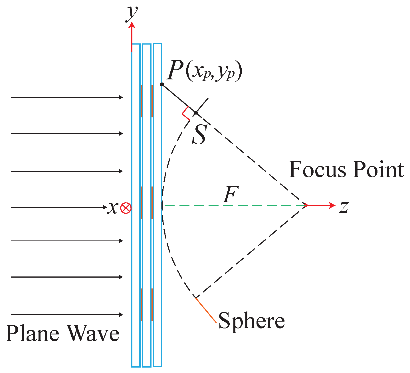
2.1. Principle of Meta-Window

The design of a meta-window aims to facilitate efficient indoor penetration of millimeter-wave signals. Inspired by optical lenses that focus light, precise phase modulation and strategic arrangement of the meta-window’s unit cells enable the construction of an electromagnetic planar metasurface lens for the target frequency band (see Figure 1). As a plane electromagnetic wave passes through the meta-window, it experiences a specific phase compensation distribution, resulting in coherent interference at the focal plane—analogous to refraction in conventional lenses [37].
For any point P ( x P , y P ) on the meta-window (where ( x P , y P ) denotes the coordinates of point P relative to the center of the window), we define its projection onto a spherical surface as S, and denote the Euclidean distance between P and S as P S ¯ . To achieve a desired focal length F, the required phase compensation φ ( x P , y P ) at point P ( x P , y P ) must satisfy the following equation [37]:
φ ( x P , y P ) = k 0 · P S ¯ = k 0 · ( F 2 + ( x P 2 + y P 2 ) F )
Here, k 0 represents the total wavevector of an electromagnetic wave in free space. F represents the focal length. To realize the meta-window, the initial step involves designing a unit cell structure capable of providing a 0–360 ° phase shift at the target frequency. Metasurfaces based on the Pancharatnam–Berry (PB) phase [38] are well-established for introducing phase shifts to circularly polarized electromagnetic waves through simple rotation of the unit cell, without altering its physical dimensions.
Our proposed meta-window design leverages the PB-phase principle, benefiting from geometric phase control to achieve the desired electromagnetic functionality while maintaining transparency of the glass substrate. When an electromagnetic wave is incident on the unit cell, a geometric phase shift of ± 2 θ occurs in the cross-polarized component of the transmitted wave upon rotation of the unit cell by an angle θ .
The transmission process and generation of this geometric phase can be described using Jones matrices [39] (Equations (2) and (3)).
E + t E t = J θ E + in E in
J θ = 1 2 [ t u u + t v v + i ( t u v t v u ) ] 1 2 [ t u u t v v i ( t u v + t v u ) ] e ( i 2 θ ) 1 2 [ t u u t v v + i ( t u v + t v u ) ] e ( i 2 θ ) 1 2 [ t u u + t v v i ( t u v t v u ) ]
Here, E + t and E t represent the right-handed circularly polarized (RCP) and left-handed circularly polarized (LCP) components of the transmitted wave, respectively, while E + in and E in denote the corresponding incident wave components. J θ is the Jones matrix, where θ represents the angle between the u v axis and the x y axis for an anisotropic unit cell. The local coordinate system of the unit cell is defined by u and v, with the x and y axes representing Cartesian coordinates. Furthermore, t u u and t v v denote the complex transmission amplitudes along the u and v axes, respectively. Interaction with the anisotropic unit cell yields a transmitted field comprising the original polarization state without phase alteration, alongside orthogonally polarized components exhibiting a geometric phase shift of 2 θ . Consequently, the Jones matrix can be used to design the rotation angles of the unit cells to achieve specific phase shifts for incident electromagnetic waves.

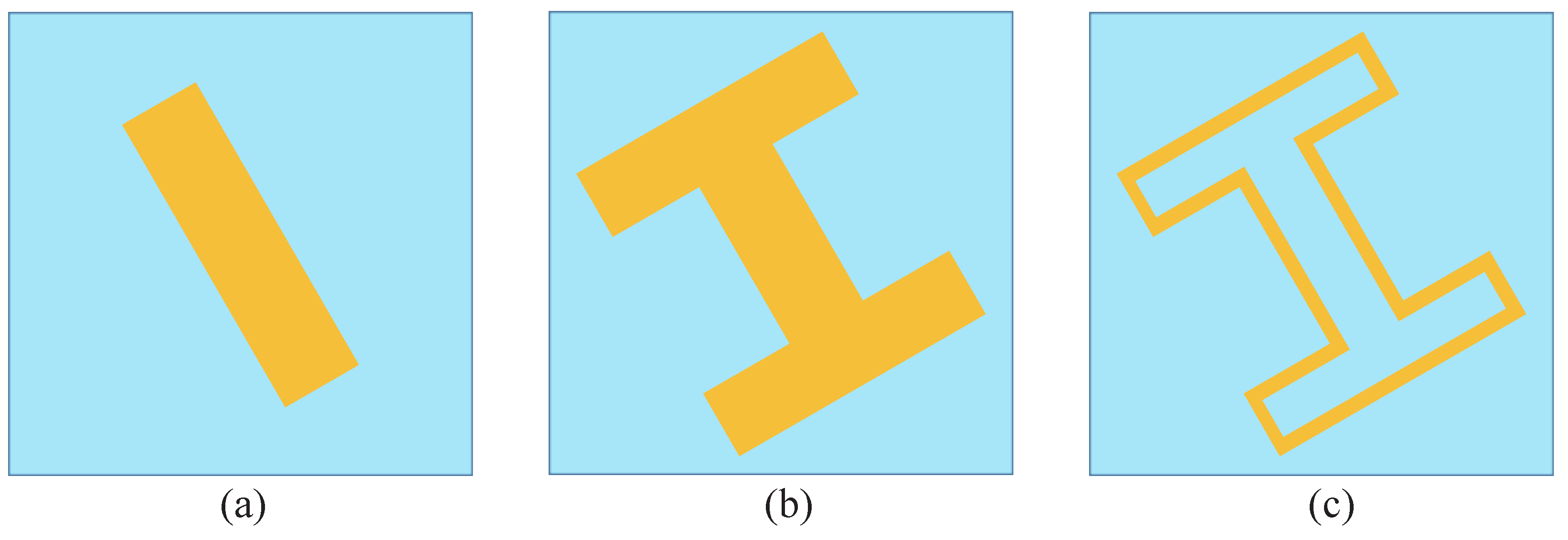
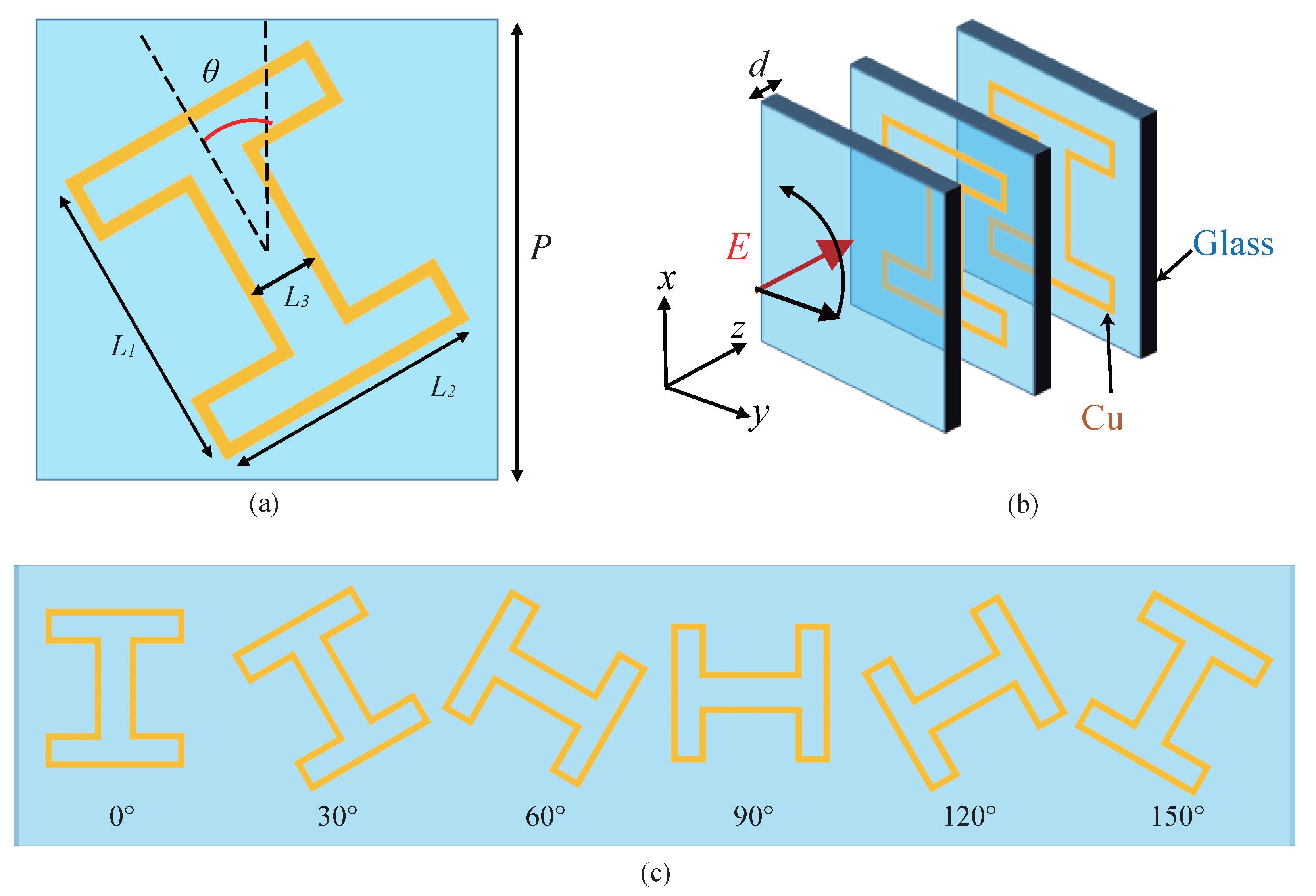
2.2. Design and Simulation of Meta-Window Unit Cell

In optics, phase modulation of circularly polarized light can be achieved by rotating the orientation of a half-wave plate realized through birefringence, which is an application of geometric phase theory. Analogously, we need to design a corresponding “half-wave plate” based on anisotropic properties in the millimeter-wave frequency band.
For electromagnetic waves, a common approach to achieving anisotropic responses involves incorporating rectangular metallic bars with different lengths and widths, as illustrated in Figure 2a. This design exploits the variation in effective current path length along different directions to realize anisotropy. By rotating the unit cell counterclockwise, a phase shift twice the rotation angle can be introduced in the cross-polarized transmitted wave. However, this simple patch design is only effective within a limited frequency band. At higher mmWave frequencies, the size of the unit cell becomes significantly smaller. The skin effect in conductors concentrates effective current flow at surface edges. Considering both enhanced electromagnetic response and fabrication convenience, we selected an “H”-shaped structure (Figure 2b), which ensures unit cell anisotropy while increasing electric field induction strength along two orthogonal directions. To further reduce metal area and improve transmittance over the visible spectrum without compromising electromagnetic performance, the “H” shape was optimized by removing material from its interior, retaining only narrow metallic linewidths at the edges. This design maximizes anisotropy and effectively enhances electric field excitation in both orthogonal directions, thereby improving electromagnetic wave manipulation capabilities. The reduced metal coverage also minimizes impact on visible transparency. Consequently, the rectangular metallic bars evolved into a hollow “H”-shaped structure composed of fine metallic lines (Figure 2c).
A single layer of fine metallic lines on a glass substrate is insufficient to achieve adequate electromagnetic phase accumulation. To meet equivalent half-wave plate phase requirement and enhance electromagnetic control, multiple layers of identical unit substructures are stacked to form the final meta-window unit cell structure, as shown in Figure 3.
As shown in Figure 3a, the unit cell comprises a hollow “H”-shaped substructure formed by fine metal lines on a square glass substrate. To enhance phase accumulation, two identical layers of this substructure are stacked, increasing the effective thickness. Furthermore, as depicted in Figure 3b, an additional layer of bare glass is added atop one of the metal layers to improve environmental stability and protect the metallic structures from corrosion, facilitating integration into building materials. Figure 3c illustrates the schematic of unit cell rotation angles, showing six rotated elements with a linear phase difference of 30 ° between adjacent cells.
Figure 3a presents the key dimensional parameters of the unit cell. P denotes the periodicity of the basic structure; θ represents the angle between the symmetry axis of the “H”-shaped metal pattern and the y-axis in the x o y plane. The total length and width of the “H”-shape are defined as L 1 and L 2 , respectively, with a uniform width of L 3 for the hollow sections. The fine metal lines have a width w and thickness t. Due to rotational symmetry around the z-axis at its geometric center, the “H”-shape exhibits rotational invariance within the periodic environment. The optimized design parameters are detailed in Table 1.
The unit cell utilizes low-cost soda-lime glass, which is commonly used in windows, bottles, and containers. Within the 26–30 GHz frequency range, this glass exhibits a relative permittivity of 7.35 and a loss tangent of 0.02, as specified by the manufacturer. Copper was selected as the metallic component of the unit structure.
The proposed unit cell was modeled and simulated using full-wave analysis in CST Studio Suite. The simulation geometry places the unit cell on the x o y -plane with its normal vector aligned along the positive z-axis. A frequency range of 25–32 GHz was employed, utilizing Floquet periodic boundary conditions and a normally incident left-hand circularly polarized (LCP) electromagnetic wave as the excitation source. The amplitude and phase responses were extracted from the calculated S 21 parameters.
It is crucial to note that PB-phase modulation induced by rotating unit cells affects only the portion of the transmitted wave undergoing polarization conversion (e.g., from LCP to RCP); scattered fields without polarization conversion (e.g., LCP to LCP) remain unmodulated. Figure 4a presents the transmissivity for polarization conversion ( T R L , solid lines) and non-polarization conversion ( T L L , dotted lines) across a frequency range of 25–32 GHz, for various rotation angles ( θ = 0 ° , 30 ° , 60 ° , and 90 ° ) with normally incident LCP waves. The transmissivity magnitudes remain relatively stable with changes in θ , remaining approximately within 3 dB from 25 to 31 GHz. While maximizing unit cell efficiency is not the primary focus, we prioritize bandwidth and maintaining a sufficiently low metal area to ensure transparency in the visible spectrum of the meta-window. The metal pattern occupies an area of 0.55 mm 2 within a unit cell area of 9 mm 2 , resulting in a metal coverage ratio of approximately 6.11%. As shown in the Figure 4b, the phase shifts exhibit approximately linear variations across the 25–32 GHz frequency range. Compared to the 0 ° reference state, unit cells rotated by 30 ° , 60 ° , and 90 ° introduce phase deviations of approximately 60 ° , 120 ° , and 180 ° , respectively. These results align with the theoretical predictions for geometric phase (Equation (3)), validating the low-dispersion phase modulation characteristics of the designed structure.

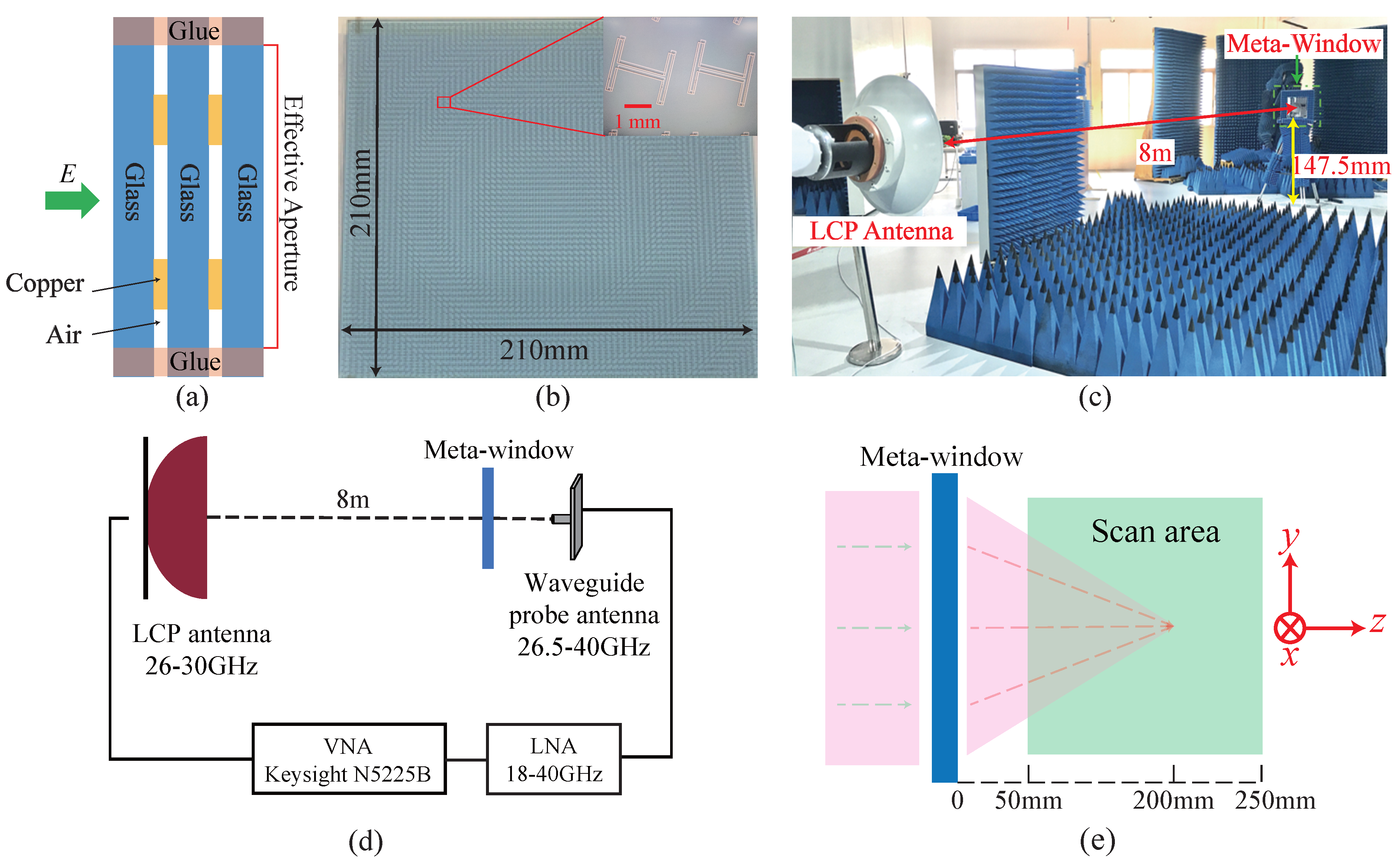
2.3. Design and Implementation of Meta-Window

Based on the proposed unit cells, we designed a planar glass lens to focus transmitted 28 GHz mmWave. The phase center was defined at the geometric center of the meta-window. This window comprises a 69 × 69 array of unit cells, with an aperture size of 207 mm × 207 mm and a focal length of 200 mm.
The calculated rotation angle distribution for the meta-window unit cells, based on Equation (1), is shown in Figure 5 (only the first quadrant is displayed). To evaluate the focusing performance of this meta-window, electric field simulations were conducted using CST Studio, as shown in Figure 6. The excitation source was a plane wave with left-hand circular polarization (LCP), and the electric field distribution was observed on the transmission side of the window. A vertical cross-section containing the focal point was analyzed to more clearly illustrate the focusing effect.
Figure 6 illustrates the distribution of the transmitted electric field from the designed meta-window with the phase profile defined in Equation (1) at 28 GHz. Specifically, Figure 6a shows the field distribution in the x o z -plane, while Figure 6b presents it in the y o z -plane. The simulation results demonstrate strong focusing at the designed 28 GHz frequency, forming an approximately linear focal line centered around 195 mm. This is likely due to the finite size of the metasurface unit cells, which results in a relatively uniform phase shift across each element when interacting with the incident electromagnetic wave. Consequently, the realized phase distribution deviates from the ideal continuous phase modulation required by Equation (1).
This study utilizes a combined physical vapor deposition (PVD) and chemical etching (CE) process to fabricate high-precision metallic wire patterns on glass substrates. PVD is employed for depositing uniform, dense metallic thin films, followed by CE to selectively remove excess material and achieve precise patterning. The fabrication procedure consists of the following steps:
  • Substrate Preparation: Glass substrates undergo a two-stage pretreatment process involving cleaning and surface activation prior to metal deposition.
  • Metal Deposition: Copper was deposited onto the glass substrate via sputtering, resulting in a uniform film thickness of 600 nm.
  • Mask Fabrication: Photolithography was used for pattern transfer and mask preparation, including photoresist coating, exposure, and development.
  • Patterning via Chemical Etching: Unprotected metal regions were selectively removed using wet chemical etching to form the final metallic wire patterns. Wet etching was chosen for its process simplicity, low cost, and scalability for large-area fabrication, resulting in a wire width of 50 μ m.
  • Layer Stacking: Multilayer structures are edge bonded with adhesive, maintaining an air gap between layers, as illustrated in Figure 7a.
Existing technologies allow for metal deposition with nanoscale precision (below 5 nm) and chemical etching with sub-micron accuracy (0.1 μ m). The processes selected for this study significantly exceed the dimensional requirements of the designed 600 nm thickness and 50 μ m wire width, ensuring adequate manufacturing fidelity.
Based on simulation results, we fabricated a 28 GHz meta-window prototype (Figure 7b). The experimental setup for near-field mapping measurements to characterize focusing performance is illustrated in Figure 7c,d, utilizing a robotic arm. A source horn antenna emitting a normally incident left-hand circularly polarized (LCP) plane wave was positioned at the far-field of the meta-window, while a waveguide probe antenna mounted on the robotic arm scanned the electric field distribution. To satisfy far-field requirements for the high-gain antenna, the distance between the LCP horn antenna and the prototype was 8 m. The horn antenna was connected to a Keysight N5225B vector network analyzer (VNA), and the waveguide probe antenna was cascaded with a low-noise amplifier (LNA) before connection to the VNA. The central axes of both antennas were aligned. A coordinate system established for the experiment is shown in Figure 7e. The meta-window was positioned on the x o y -plane, and the waveguide probe scanned within a region of ±100 mm along both the x and y directions, and from 50 to 250 mm along the z direction, with a scan step of 2 mm.
To quantitatively characterize the focusing gain of the meta-window, the focusing gain is defined as
G p = 10 lg E p 2 E 0 2 = 10 lg E p x 2 + E p y 2 E 0 x 2 + E 0 y 2
where G p represents the logarithmic gain of the meta-window at the focal point, and | E p | and | E 0 | are the amplitudes of the electric field at the focal point and incident on the front surface, respectively. E p x and E p y (and E 0 x and E 0 y ) denote the x- and y-components of | E p | ( | E 0 | ). Due to the symmetry of the meta-window and incident source, the z-component of the electric field along the central axis is zero for plane wave incidence; therefore, only the x- and y-components were measured experimentally.
Figure 8 presents the measured | E x | pattern normalized by | E 0 x | in the y o z -plane at five frequencies near the designed frequency of 28 GHz. Compared to corresponding CST Studio simulations, experimental results revealed a slightly larger focal spot and longer focal length. As shown in Figure 8, the measured focal spot exhibits a spindle-like shape with a width exceeding that obtained from simulation. This discrepancy likely stems from fabrication imprecision, leading to an uneven phase gradient distribution and subsequent diffusion of the focal position. While our fabrication process aims for high precision, inherent variations in metal deposition thickness (±5 nm) and etching accuracy (±0.1 μ m) can introduce slight geometric distortions in the meta-window structures, contributing to the observed discrepancies. Moreover, deviation of the input signal frequency from the design target results in focal point displacement. According to Equation (1), with a constant additional phase compensation, decreasing frequency (and thus wavenumber) leads to a shorter focal length F, and vice versa. Furthermore, the magnitude of this focal length variation is inversely proportional to the aperture size of the meta-window which represents the maximum distance over which an additional phase shift is applied. Consistent with the theoretical predictions and simulations, the measured focal point shifts with frequency; increasing frequency results in increased distance between the focal point and the meta-window. Overall, the experimental results demonstrate good agreement with the simulations, validating the effective focused transmission of mmWave signals achieved by the designed meta-window.
We further conducted experimental tests to characterize the focal length, converging gain, and transmittance over visible spectrum of the designed meta-window. The results are presented in Figure 9. Figure 9a demonstrates that the measured focal length remains stable between 180 and 200 mm across the frequency range of 26–30 GHz—consistent with simulation results. The average focusing gain within the 26.5–30 GHz range reaches at least 20 dB, approximately 2.5 dB lower than simulated values; a peak gain of 23.8 dB was measured at 28.5 GHz (Figure 9b). Transmittance over visible spectrum measurements indicate a value of 74.93% for the designed meta-window (Figure 9c). This design successfully achieves dual transparency for both visible light and millimeter waves.

3. MmWave Communication Demonstrations Based on 28 GHz Meta-Window

A primary challenge in millimeter-wave communication is signal penetration loss during transmission from outdoor to indoor environments. The designed meta-window operating in the millimeter-wave band aims to address this issue and enhance indoor coverage performance. By focusing and guiding millimeter-wave signals, the meta-window effectively increases signal strength, thereby improving both penetration efficiency and indoor coverage quality. To validate these ideas, we conducted experimental demonstrations of millimeter-wave communication tests based on our proposed 28 GHz Meta-window.

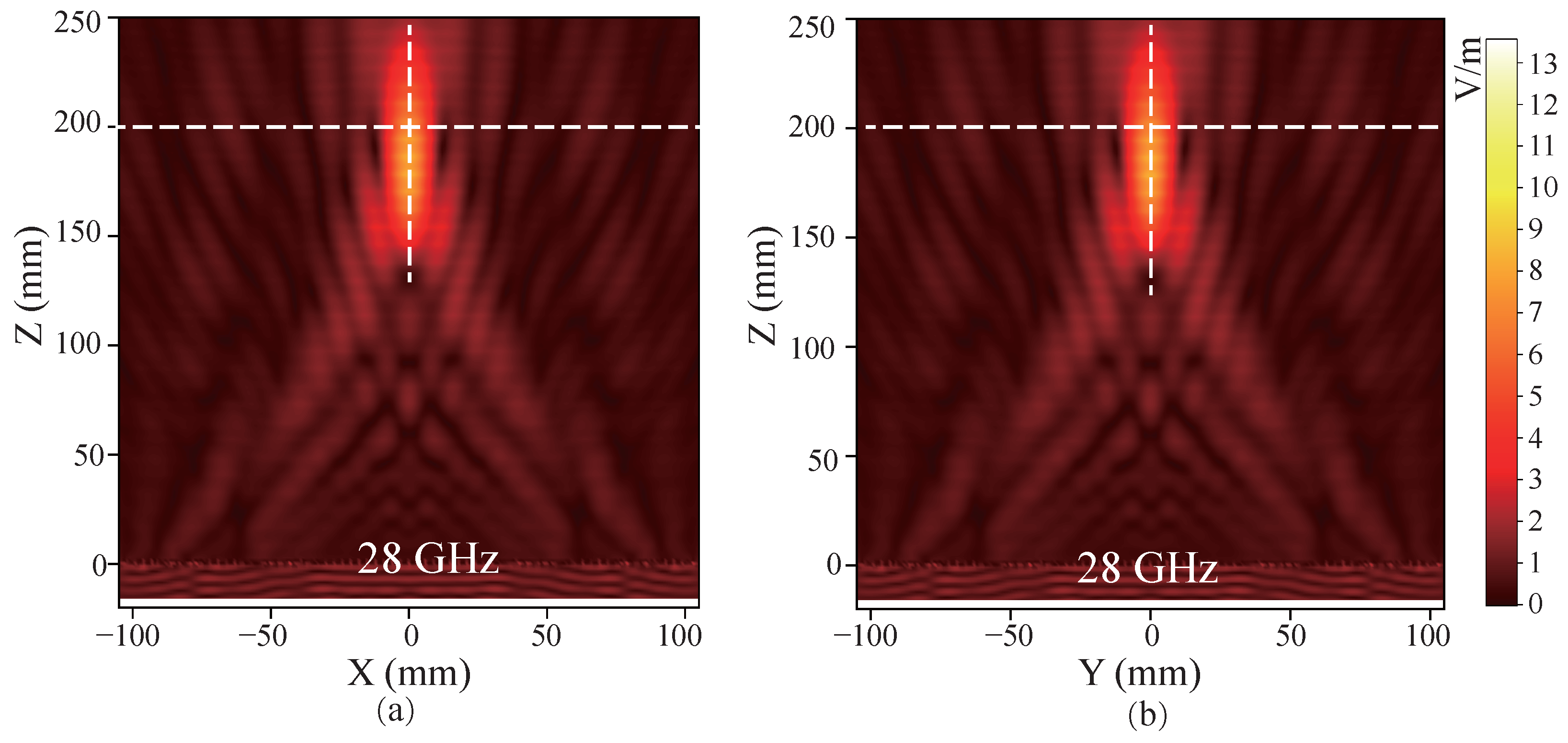
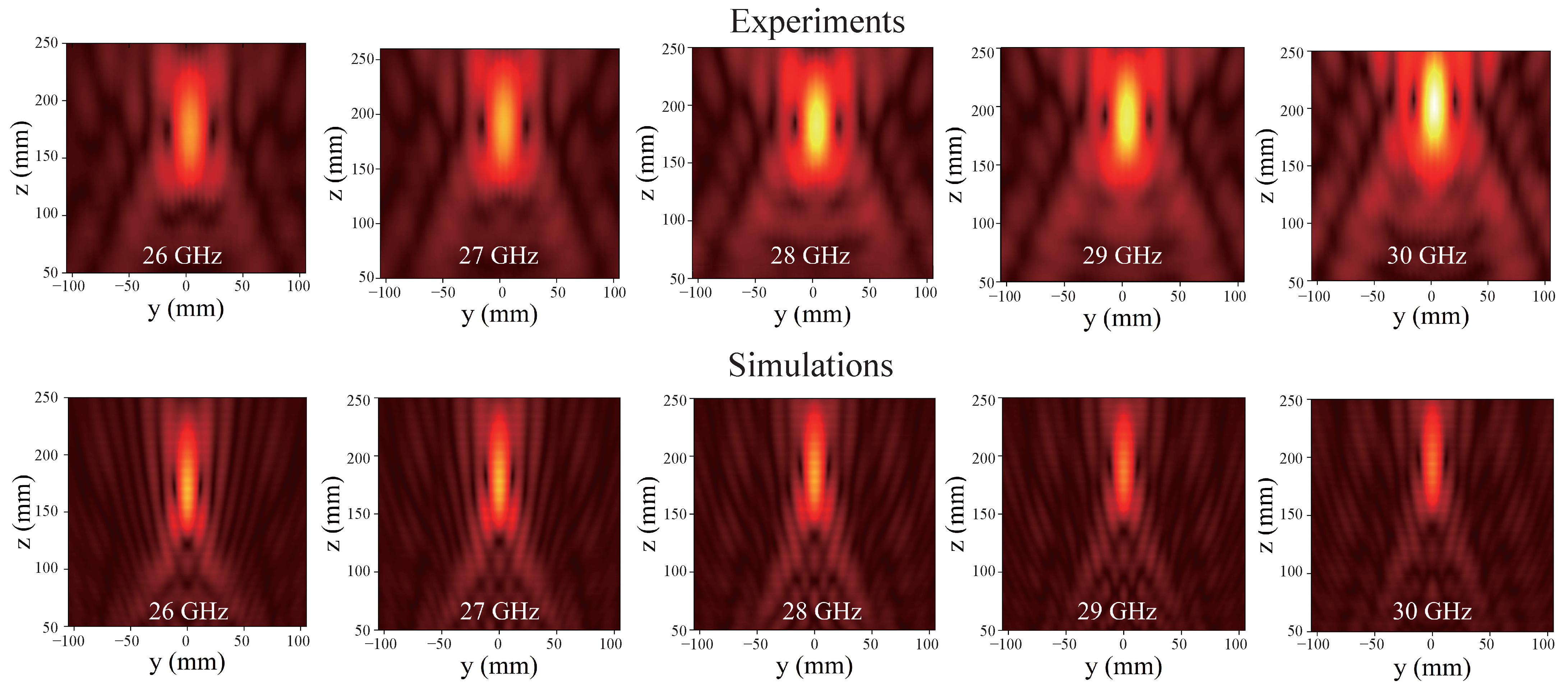
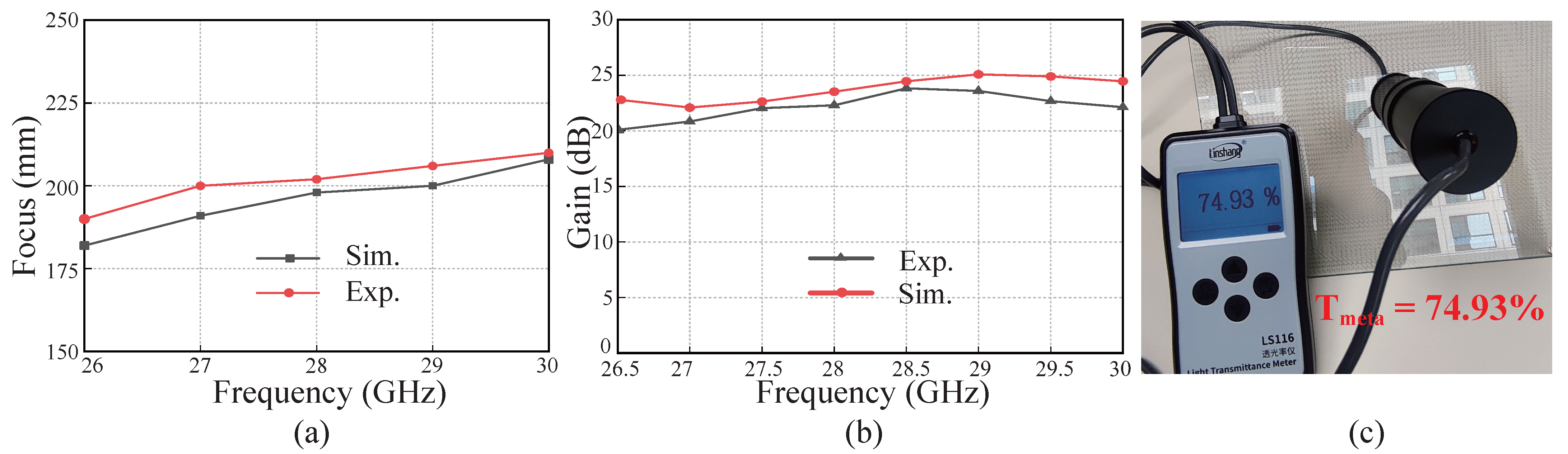
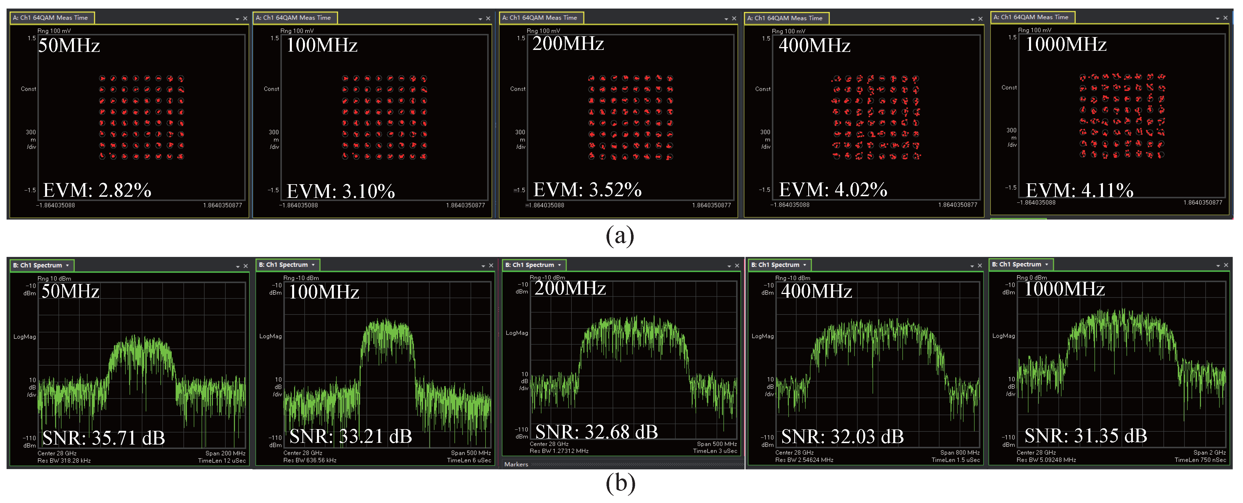
3.1. MmWave Communication Performance After Meta-Window Focusing

We designed a proof-of-concept experiment to evaluate the communication performance of millimeter-wave signal penetration through the meta-window, verifying its ability to focus and enhance the signal. The experimental setup is illustrated in Figure 10. As shown in Figure 10a, an arbitrary waveform generator (AWG, M8195A, Keysight Technologies Inc., Santa Rosa, CA, USA) generates the source signal, which is then radiated via a horn antenna. To minimize reflections and multipath interference, the output power was set to −30 dBm. At the receiver, a standard gain horn antenna captures the millimeter-wave signal, followed by amplification using a low-noise amplifier (LNA, LNA-1840, Fragrant Mountain Microwave, Zhongshan, Guangdong, China) with a gain of 38–40 dB. The amplified signal is then demodulated and analyzed by a signal analyzer (UXA, N9042B, Keysight Technologies Inc., Santa Rosa, CA, USA). Figure 10b shows the experimental setup in situ. The transmitting (Tx) and receiving (Rx) antennas, featuring small apertures, were separated by a distance of 2 m, ensuring operation within their respective far-field regions. The receiver antenna’s distance from the meta-window is 200 mm.
Initially, we assessed the demodulation performance of the direct communication signal without the focusing enhancement provided by the meta-window. The transmitting antenna emitted a single-carrier 64-QAM modulated signal with bandwidths of 50 MHz, 100 MHz, 200 MHz, 400 MHz, and 1 GHz. The received signal was demodulated using 89600 PathWave VSA analysis software (Build 26.20.223.0) in UXA, and its constellation diagram, error vector magnitude (EVM), and signal-to-noise ratio (SNR) were evaluated. Results are presented in Table 2, demonstrating a rapid decrease in SNR and significant deterioration of EVM as bandwidth increased without the meta-window’s focusing effect. At 1 GHz bandwidth, the measured SNR was only 9.61 dB, with an EVM of 88.47%, precluding clear constellation diagram visualization.
Subsequently, we evaluated signal demodulation performance with the meta-window’s focusing enhancement. Analysis results for SNR and EVM are presented in Figure 11 and Table 2. The experimental results indicate that the meta-window provides a signal gain of up to 20 dB. According to 3GPP standards, the EVM requirement for demodulating 64-QAM millimeter-wave signals is 8%. Integrating the proposed meta-window improved the SNR from 17.21 dB to 35.71 dB and reduced the EVM from 14.35% to 2.82% at a 50 MHz bandwidth. At 1 GHz bandwidth, the SNR increased from 9.61 dB to 31.03 dB and the EVM decreased from 88.47% to 4.11%, meeting 3GPP standards. These results validate the feasibility and effectiveness of the proposed meta-window based millimeter-wave indoor penetration system for practical applications.

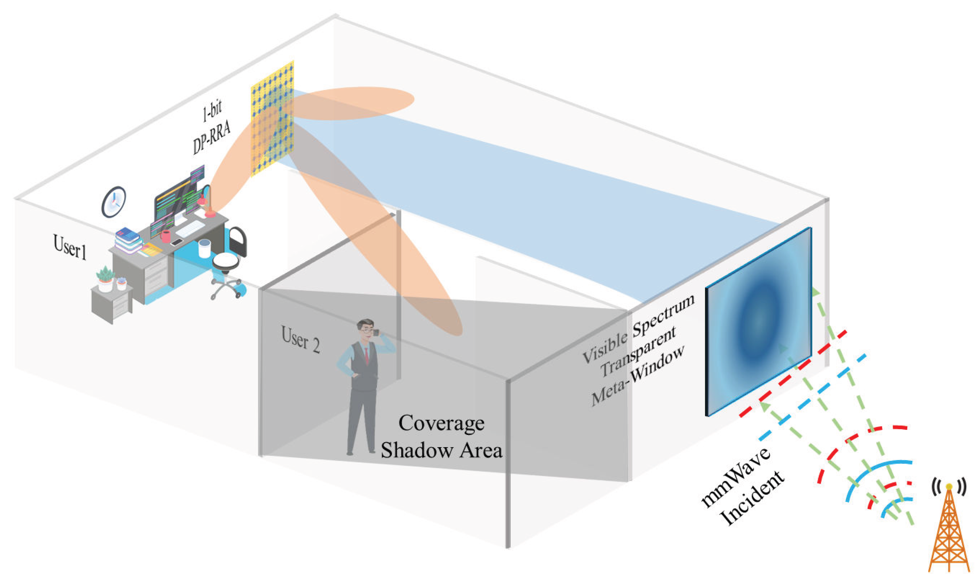
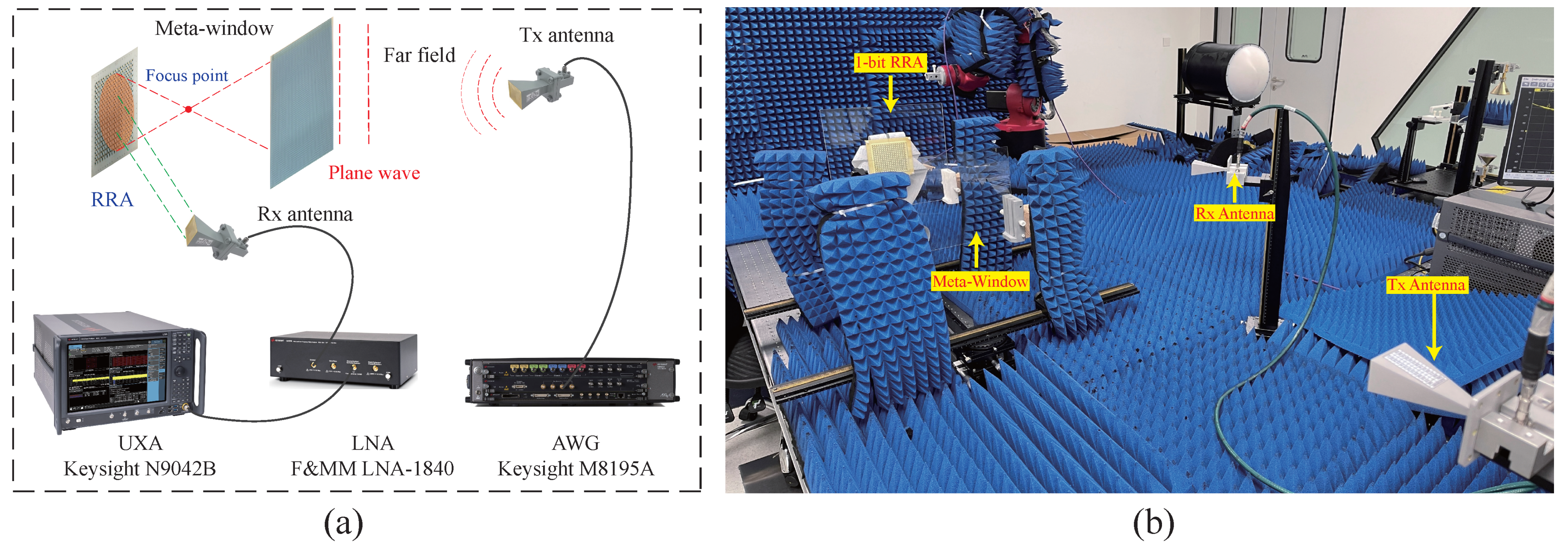
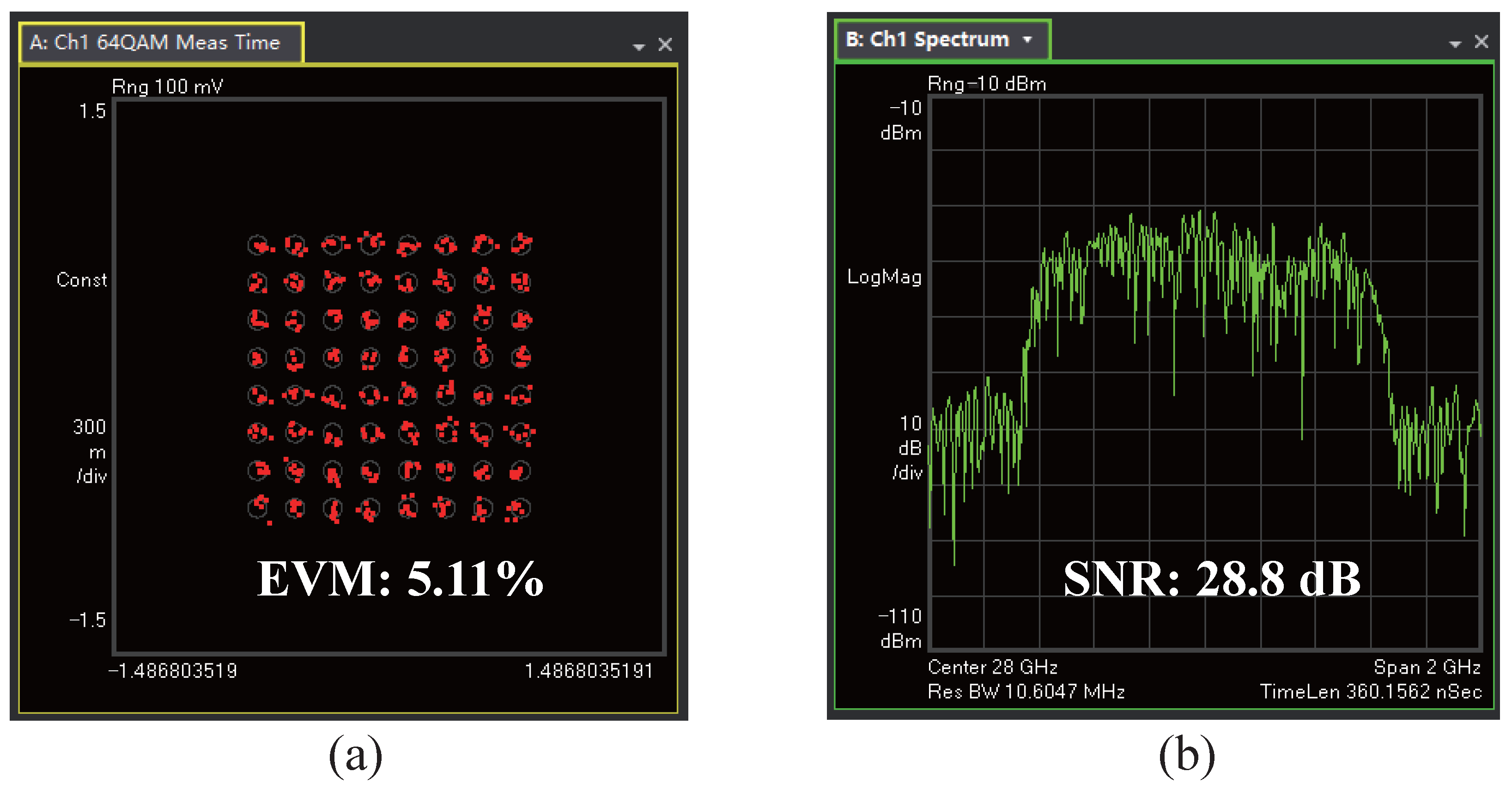
3.2. MmWave Communication Performance of Meta-Window and 1-Bit DP-RRA Cascaded System

Millimeter-wave signals exhibit short wavelengths and highly directional beams, significantly limiting their diffraction capability. To enhance indoor coverage, a reconfigurable reflective metasurface antenna array can be cascaded with the meta-window to steer the focused beam and achieve comprehensive coverage. We employed a cost-effective 1-bit dual-polarized reconfigurable reflecting metasurface antenna array (DP-RRA), suitable for compact millimeter-wave communication systems [40].
The 1-bit DP-RRA cascaded with the meta-window in this work features two sets of orthogonal and rotationally symmetrical dipoles, each integrating only one p-i-n diode, which reduces the cost of active components and simplifies the layout of biasing circuits. By controlling the states of the corresponding-polarized diode, independent 1-bit phase shifts can be achieved for dual-linear polarizations. The DP-RRA integrates 16 × 16 unit cells, with an effective aperture of 83.2 × 83.2 mm 2 . The RRA demonstrates peak gains of 19.4 dBi and 20.1 dBi for x- and y-polarization, respectively, corresponding to aperture efficiencies of 13.3% and 15.7%. More detailed specifications are summarized in Table 3.
As shown in Figure 12, the 1-bit DP-RRA utilizes a simple linear phase gradient to redistribute the signal to cover shadow areas, leveraging its directional coverage capabilities.
The experiment setup is shown in Figure 13. Communication performance validation employed the same 1 GHz bandwidth signal configuration described in Section 3.1. To mitigate grating lobes arising from 1-bit DP-RRA reflected beams [41], spherical wave excitation was utilized, which is well-suited to the meta-window’s converging characteristics. Positioning the 1-bit DP-RRA after the focal point of the meta-window ensures a spherical beam with pseudorandom wavefront phase variation, avoiding grating lobes induced by plane wave incidence. Consequently, the 1-bit DP-RRA effectively directs the signal in a single beam, optimizing indoor coverage performance. Signal reception and analysis were performed using an N9042B UXA signal analyzer and 89600 PathWave VSA software to measure constellation diagrams, EVM, and SNR, evaluating the feasibility and performance of the proposed cascaded 28-GHz meta-window and 1-bit DP-RRA indoor coverage prototype.
During experimentation, we evaluated received signal quality at various deflection angles by adjusting the phase gradient of the 1-bit DP-RRA, thereby analyzing the improvement in millimeter-wave indoor penetration coverage provided by this cascaded system.
Figure 14 shows the demodulation results for a 1 GHz bandwidth 64-QAM millimeter-wave signal with a beam deflection angle of −30 ° achieved using the cascaded meta-window and 1-bit DP-RRA indoor penetration coverage prototype.
The measured SNR was 28.8 dB, corresponding to an EVM value of 5.11%. Additional test results for various angles are presented in Table 4. As shown in Table 4, the EVM performance of the received millimeter-wave signals remained within the 3GPP requirement of 8% for 64-QAM signals across deflection angles of ±40 ° , despite decreasing SNR and increasing EVM with larger deflection angles after cascaded meta-window and DP-RRA beam steering.

4. Conclusions

Millimeter-wave (mmWave) signals are characterized by high penetration loss, which pose significant challenges for outdoor-to-indoor communication coverage. To address this challenge, this paper proposes a novel 28 GHz meta-window design aimed at mitigating the penetration loss of mmWave signals. This meta-window functions as an electromagnetic planar metasurface lens at 28 GHz by precisely rotating fine metal line patterns on a glass substrate to achieve optimized phase compensation. This facilitates signal convergence enhancement from outdoor to indoor environments, mitigating high penetration loss inherent in millimeter-wave communication. The fabrication process involves sputtering and etching fine metal lines onto standard soda-lime glass, enabling 0–360 ° phase tunability within the 25–32 GHz band based on geometric phase principles. The design offers a streamlined workflow with regular unit cell structures, supporting scalable mass production. This meta-window exhibits a 3 dB gain bandwidth exceeding 3.5 GHz (26.5–30 GHz) and a transmittance over the visible spectrum of 74.93%. In 28 GHz millimeter-wave communication experiments, it provided over 20 dB of received power and SNR gain for a 1 GHz bandwidth 64QAM signal, with a demodulation vector error magnitude of 4.11%, meeting the 3GPP standard requirement (≤8%). Installation of the meta-window in existing building infrastructure offers a pathway towards significant enhancement of indoor millimeter-wave signal strength and improved penetration. Finally, we also presents a cascaded system combining the meta-window with a 1-bit DP-RRA for improved indoor coverage; received signal quality (EVM ≤ 6.32%) within a scanning angle of ±40 ° meets the 3GPP demodulation standard (≤8%). This approach effectively addresses outdoor-to-indoor signal penetration and wide-area coverage challenges in outdoor-to-indoor scenarios, providing valuable reference for future designs of enhanced millimeter-wave indoor coverage systems.

Author Contributions

C.Y. (Chun Yang), C.Y. (Chuanchuan Yang), and C.Z. conceived the idea for this work. C.Z. and H.L. supervised the research. C.Y. (Chun Yang) was responsible for the design of the unit cell and fabricated the meta-window. C.Y. (Chun Yang) and C.Z. built the measurement system and conducted experimental measurements. C.Y. (Chun Yang), C.Y. (Chuanchuan Yang), and C.Z. performed data processing and analysis. All authors have read and agreed to the published version of the manuscript.

Funding

This work was partly supported by the National Key Research and Development Program of China (No. 2023YFB2906102) and the Shenzhen Science and Technology Program (No. KJZD20231023100502005).

Institutional Review Board Statement

Not applicable.

Informed Consent Statement

Not applicable.

Data Availability Statement

The data supporting this study’s findings are available from the corresponding author upon reasonable request.

Conflicts of Interest

The authors declare no conflicts of interest.

References

  1. Miao, H.; Zhang, J.; Tang, P.; Tian, L.; Zhao, X.; Guo, B.; Liu, G. Sub-6 GHz to mmWave for 5G-advanced and beyond: Channel measurements, characteristics and impact on system performance. IEEE J. Sel. Areas Commun. 2023, 41, 1945–1960. [Google Scholar] [CrossRef]
  2. Hong, W.; Jiang, Z.H.; Yu, C.; Hou, D.; Wang, H.; Guo, C.; Hu, Y.; Kuai, L.; Yu, Y.; Jiang, Z.; et al. The role of millimeter-wave technologies in 5G/6G wireless communications. IEEE J. Microw. 2021, 1, 101–122. [Google Scholar] [CrossRef]
  3. Rappaport, T.S.; Sun, S.; Mayzus, R.; Zhao, H.; Azar, Y.; Wang, K.; Wong, G.N.; Schulz, J.K.; Samimi, M.; Gutierrez, F. Millimeter wave mobile communications for 5G cellular: It will work! IEEE Access 2013, 1, 335–349. [Google Scholar] [CrossRef]
  4. Giordani, M.; Zorzi, M. Satellite communication at millimeter waves: A key enabler of the 6G era. In Proceedings of the 2020 International Conference on Computing, Networking and Communications (ICNC), Big Island, HI, USA, 17–20 February 2020; pp. 383–388. [Google Scholar]
  5. Uwaechia, A.N.; Mahyuddin, N.M. A comprehensive survey on millimeter wave communications for fifth-generation wireless networks: Feasibility and challenges. IEEE Access 2020, 8, 62367–62414. [Google Scholar] [CrossRef]
  6. Zekri, A.B.; Ajgou, R.; Chemsa, A.; Ghendir, S. Analysis of outdoor to indoor penetration loss for mmwave channels. In Proceedings of the 2020 1st International Conference on Communications, Control Systems and Signal Processing (CCSSP), El Oued, Algeria, 16–17 May 2020; pp. 74–79. [Google Scholar]
  7. Kodra, S.; Barbiroli, M.; Vitucci, E.M.; Fuschini, F.; Degli-Esposti, V. Mm-Wave Building Penetration Losses: A Measurement-Based Critical Analysis. IEEE Open J. Antennas Propag. 2024, 5, 404–413. [Google Scholar] [CrossRef]
  8. Lee, Y.C.; Oh, S.S.; Byeon, C.W.; Aziding, K.; Cho, B.L. Impact of window penetration loss on building entry loss from 3.5 to 24 GHz. IEEE Access 2021, 9, 138571–138579. [Google Scholar] [CrossRef]
  9. Khawaja, W.; Ozdemir, O.; Yapici, Y.; Erden, F.; Guvenc, I. Coverage enhancement for NLOS mmWave links using passive reflectors. IEEE Open J. Commun. Soc. 2020, 1, 263–281. [Google Scholar] [CrossRef]
  10. Naqvi, S.H.R.; Ho, P.H.; Peng, L. 5G NR mmWave indoor coverage with massive antenna system. J. Commun. Netw. 2021, 23, 1–11. [Google Scholar] [CrossRef]
  11. Fu, C.; Han, L.; Liu, C.; Lu, X.; Sun, Z. Combining Pancharatnam–Berry phase and conformal coding metasurface for dual-band RCS reduction. IEEE Trans. Antennas Propag. 2021, 70, 2352–2357. [Google Scholar] [CrossRef]
  12. Li, Y.; Lin, J.; Guo, H.; Sun, W.; Xiao, S.; Zhou, L. A tunable metasurface with switchable functionalities: From perfect transparency to perfect absorption. Adv. Opt. Mater. 2020, 8, 1901548. [Google Scholar] [CrossRef]
  13. Ji, W.; Chang, J.; Xu, H.X.; Gao, J.R.; Gröblacher, S.; Urbach, H.P.; Adam, A.J. Recent advances in metasurface design and quantum optics applications with machine learning, physics-informed neural networks, and topology optimization methods. Light Sci. Appl. 2023, 12, 169. [Google Scholar] [CrossRef]
  14. Lu, C.; Mei, Z.L.; Tang, W.X.; Cui, T.J. Manipulating scattering features by metamaterials. EPJ Appl. Metamater. 2016, 3, 3. [Google Scholar] [CrossRef]
  15. Fu, C.; Sun, Z.; Han, L.; Liu, C. Dual-bandwidth linear polarization converter based on anisotropic metasurface. IEEE Photonics J. 2020, 12, 1–11. [Google Scholar] [CrossRef]
  16. Fu, C.; Han, L.; Liu, C.; Sun, Z.; Lu, X. Dual-band polarization conversion metasurface for RCS reduction. IEEE Trans. Antennas Propag. 2020, 69, 3044–3049. [Google Scholar] [CrossRef]
  17. Cui, T.J.; Qi, M.Q.; Wan, X.; Zhao, J.; Cheng, Q. Coding metamaterials, digital metamaterials and programmable metamaterials. Light Sci. Appl. 2014, 3, e218. [Google Scholar] [CrossRef]
  18. Basar, E.; Di Renzo, M.; De Rosny, J.; Debbah, M.; Alouini, M.S.; Zhang, R. Wireless communications through reconfigurable intelligent surfaces. IEEE Access 2019, 7, 116753–116773. [Google Scholar] [CrossRef]
  19. Di Renzo, M.; Zappone, A.; Debbah, M.; Alouini, M.S.; Yuen, C.; De Rosny, J.; Tretyakov, S. Smart radio environments empowered by reconfigurable intelligent surfaces: How it works, state of research, and the road ahead. IEEE J. Sel. Areas Commun. 2020, 38, 2450–2525. [Google Scholar] [CrossRef]
  20. Liang, J.C.; Cheng, Q.; Gao, Y.; Xiao, C.; Gao, S.; Zhang, L.; Jin, S.; Cui, T.J. An angle-insensitive 3-bit reconfigurable intelligent surface. IEEE Trans. Antennas Propag. 2021, 70, 8798–8808. [Google Scholar] [CrossRef]
  21. Wang, M.; Liao, D.; Dai, J.Y.; Chan, C.H. Dual-polarized reconfigurable metasurface for multifunctional control of electromagnetic waves. IEEE Trans. Antennas Propag. 2022, 70, 4539–4548. [Google Scholar] [CrossRef]
  22. Chen, Y.; Ren, J.; Li, P.; Ren, X.; Wang, J.; Zhang, S.; Yin, Y. Design of 2-bit Single Linearly-Polarized Reconfigurable Intelligent Surface for Single-/Multi-Beam Scanning. IEEE Antennas Wirel. Propag. Lett. 2024, 23, 2366–2370. [Google Scholar] [CrossRef]
  23. Zhou, Y.; Ma, X.; Luo, Q.; Ma, Y.; Alexandropoulos, G.C.; Yang, X. Wideband sub-THz Reconfigurable Intelligent Surface Using Planar Tightly Coupled Dipoles. IEEE Antennas Wirel. Propag. Lett. 2024, 23, 3659–3663. [Google Scholar] [CrossRef]
  24. Machado, G.G.; Abbasi, M.A.B.; McKernan, A.; Gu, C.; Zelenchuk, D. Wideband dual-polarized 1-bit unit-cell design for mmwave reconfigurable intelligent surface. In Proceedings of the 2024 18th European Conference on Antennas and Propagation (EuCAP), Glasgow, UK, 17–22 March 2024; pp. 1–4. [Google Scholar]
  25. Liu, Y.; Liu, X.; Mu, X.; Hou, T.; Xu, J.; Di Renzo, M.; Al-Dhahir, N. Reconfigurable intelligent surfaces: Principles and opportunities. IEEE Commun. Surv. Tutor. 2021, 23, 1546–1577. [Google Scholar] [CrossRef]
  26. Kamalisarvestani, M.; Saidur, R.; Mekhilef, S.; Javadi, F. Performance, materials and coating technologies of thermochromic thin films on smart windows. Renew. Sustain. Energy Rev. 2013, 26, 353–364. [Google Scholar] [CrossRef]
  27. Castillo, M.S.; Liu, X.; Abd-AlHamid, F.; Connelly, K.; Wu, Y. Intelligent windows for electricity generation: A technologies review. Build. Simul. 2022, 15, 1747–1773. [Google Scholar] [CrossRef]
  28. Yunos, L.; Jane, M.L.; Murphy, P.J.; Zuber, K. Frequency selective surface on low emissivity windows as a means of improving telecommunication signal transmission: A review. J. Build. Eng. 2023, 70, 106416. [Google Scholar] [CrossRef]
  29. Safari, M.; He, Y.; Kim, M.; Kherani, N.P.; Eleftheriades, G.V. Optically and radio frequency (RF) transparent meta-glass. Nanophotonics 2020, 9, 3889–3898. [Google Scholar] [CrossRef]
  30. Chishti, A.R.; Aziz, A.; Qureshi, M.A.; Abbasi, M.N.; Algarni, A.M.; Zerguine, A.; Hussain, N.; Hussain, R. Optically transparent antennas: A review of the state-of-the-art, innovative solutions and future trends. Appl. Sci. 2022, 13, 210. [Google Scholar] [CrossRef]
  31. Lai, S.; Guo, Y.; Liu, G.; Liu, Y.; Fu, C.; Chang, H.; Wu, Y.; Gu, W. A high-performance ultra-broadband transparent absorber with a patterned ITO metasurface. IEEE Photonics J. 2022, 14, 4629107. [Google Scholar] [CrossRef]
  32. Meng, Z.; Tian, C.; Xu, C.; Wang, J.; Li, X.; Huang, S.; Fan, Q.; Qu, S. Optically transparent coding metasurface with simultaneously low infrared emissivity and microwave scattering reduction. Opt. Express 2020, 28, 27774–27784. [Google Scholar] [CrossRef]
  33. Luo, Y.; Huang, L.; Ding, J.; Liu, W.; Sun, B.; Xie, C.; Yang, H.; Wu, J. Flexible and transparent broadband microwave metasurface absorber based on multipolar interference engineering. Opt. Express 2022, 30, 7694–7707. [Google Scholar] [CrossRef]
  34. Kitayama, D.; Hama, Y.; Goto, K.; Miyachi, K.; Motegi, T.; Kagaya, O. Transparent dynamic metasurface for a visually unaffected reconfigurable intelligent surface: Controlling transmission/reflection and making a window into an RF lens. Opt. Express 2021, 29, 29292–29307. [Google Scholar] [CrossRef]
  35. Zu, H.R.; Wu, B.; Chen, B.; Li, W.H.; Su, T.; Liu, Y.; Tang, W.X.; He, D.P.; Cui, T.J. Optically and radiofrequency-transparent metadevices based on quasi-one-dimensional surface plasmon polariton structures. Nat. Electron. 2023, 6, 525–533. [Google Scholar] [CrossRef]
  36. Dong, S.; Zhang, C.; Yang, C.; Wu, S.; Sun, H.; Zhang, Y.; Qin, Y.; Song, X.; Xue, K.; Zhang, S.; et al. Optically transparent meta-window for satellite signal reception. Opt. Laser Technol. 2024, 176, 110949. [Google Scholar] [CrossRef]
  37. Aieta, F.; Genevet, P.; Kats, M.A.; Yu, N.; Blanchard, R.; Gaburro, Z.; Capasso, F. Aberration-Free Ultrathin Flat Lenses and Axicons at Telecom Wavelengths Based on Plasmonic Metasurfaces. Nano Lett. 2012, 12, 4932–4936. [Google Scholar] [CrossRef]
  38. Pancharatnam, S. Generalized theory of interference, and its applications: Part I. Coherent pencils. Proc. Ind. Acad. Sci. 1956, 44, 247–262. [Google Scholar] [CrossRef]
  39. Kim, J.; Yang, Y.; Badloe, T.; Kim, I.; Yoon, G.; Rho, J. Geometric and physical configurations of meta-atoms for advanced metasurface holography. InfoMat 2021, 3, 739–754. [Google Scholar] [CrossRef]
  40. Zhang, C.; Yang, C.; Dong, S.; Xue, K.; Qin, Y.; Jiang, Z.H. Cost-Effective Dual-Polarized Millimeter-Wave Reconfigurable Reflect-Array Antenna. IEEE Antennas Wirel. Propag. Lett. 2024. [Google Scholar] [CrossRef]
  41. Yin, J.; Wu, Q.; Lou, Q.; Wang, H.; Chen, Z.N.; Hong, W. Single-Beam 1 Bit Reflective Metasurface Using Prephased Unit Cells for Normally Incident Plane Waves. IEEE Trans. Antennas Propag. 2020, 68, 5496–5504. [Google Scholar] [CrossRef]
Figure 1. Schematic diagram of the meta-window principle.
Electronics 14 01893 g001
Figure 2. Unit cell structure design evolution. (a) Anisotropic metal patch structure. (b) “H”-shaped anisotropic structure. (c) Hollow “H” structure.
Electronics 14 01893 g002
Figure 3. Geometry of the proposed unit cell. (a) Top view of the unit cell. (b) Stack exploded. (c) Unit cells with different rotation angles (0 ° , 30 ° , 60 ° , 90 ° , 120 ° , 150 ° ).
Electronics 14 01893 g003
Figure 4. Simulated transmissivity performances of the proposed unit cell (with rotation angles of 0 ° , 30 ° , 60 ° , 90 ° ). (a) Transmissivity magnitude of LCP to RCP (solid line, T R L ) and LCP to LCP (dashed line, T L L ). (b) Transmissivity phase of LCP to RCP.
Electronics 14 01893 g004
Figure 5. The distribution for the meta-window unit cells in the first quadrant.
Electronics 14 01893 g005
Figure 6. Focusing performance simulations of the meta-window. (a) Focusing performance in the x o z plane. (b) Focusing performance in the y o z plane.
Electronics 14 01893 g006
Figure 7. Meta-window design and experiment setup. (a) Meta-window stackup. (b) Meta-window prototype. (c) Experimental setup. (d) Block diagram of the experiment. (e) Experimental electric field scanning region.
Electronics 14 01893 g007
Figure 8. Experiment results vs. simulations.
Electronics 14 01893 g008
Figure 9. Meta-window key parameters measurement. (a) Focal length measurement. (b) Focusing gains at several frequencies in 26.5 GHz to 30 GHz. (c) Visible transparency measurement of the meta-window.
Electronics 14 01893 g009
Figure 10. MmWave communication performance evaluatation after meta-window focusing. (a) Experimental setup diagram. (b) Photo of experiment environment.
Electronics 14 01893 g010
Figure 11. VSA analysis results of EVM and SNR for millimeter-wave signals with varying bandwidths. (a) EVM results. (b) SNR results.
Electronics 14 01893 g011
Figure 12. A cascaded system combining the meta-window with a 1-bit DP-RRA for mmWave indoor coverage scenarios.
Electronics 14 01893 g012
Figure 13. Verification of Indoor mmWave coverage via cascaded system. (a) Experimental setup diagram. (b) Photo of experiment environment.
Electronics 14 01893 g013
Figure 14. The received signal quality at a beam deflection angle of −30 ° by the cascaded system. (a) EVM of the received signal. (b) SNR of the received signal.
Electronics 14 01893 g014
Table 1. Parameters of the proposed unit cell.
ParametersValueParametersValue
P3 mmt600 nm
L 1 2 mm L 2 1.9 mm
L 3 0.3 mmw50 μ m
d1.1 mmn2
Table 2. Meta-window focusing performance of demodulation.
BW (MHz)Channel Power (dBm)SNR (dB)EVM
Without
Meta-Window
With
Meta-Window
Without
Meta-Window
With
Meta-Window
Without
Meta-Window
With
Meta-Window
50−67.50−46.3117.2135.7114.35%2.82%
100−68.14−46.5714.2333.2124.22%3.10%
200−68.66−47.0311.5832.6864.32%3.52%
400−69.42−48.2210.3132.0384.32%4.02%
1000−70.12−49.219.6131.0388.47%4.11%
Table 3. Key Feature of The 1bit DP-RRA.
ParametersValueParametersValue
Frequency (GHz)26–30Pol.DP
Bit Num.1-bitDiode Num. per unitcell2
Scanning Angle±50 ° Aperture Size ( λ 2 )8.32 × 8.32
Aperture Eff.x: 13.3%, y: 15.7%Element Num.256
Table 4. Demodulation performance under different deflection angles in general coverage section.
Deflection AngleSNREVM
−40 ° 27.30 dB6.21%
−30 ° 28.80 dB5.11%
−20 ° 29.50dB4.82%
−10 ° 30.15 dB4.18%
10 ° 29.93 dB4.20%
20 ° 29.60 dB4.79%
30 ° 28.70 dB5.03%
40 ° 27.60 dB6.32%
Disclaimer/Publisher’s Note: The statements, opinions and data contained in all publications are solely those of the individual author(s) and contributor(s) and not of MDPI and/or the editor(s). MDPI and/or the editor(s) disclaim responsibility for any injury to people or property resulting from any ideas, methods, instructions or products referred to in the content.

