Article

Achieving Low-Latency, High-Throughput Online Partial Particle Identification for the NA62 Experiment Using FPGAs and Machine Learning †

1
Sezione di Roma, Istituto Nazionale di Fisica Nucleare, P.le Aldo Moro, 2, 00185 Rome, Italy
2
Sezione di Roma Tor Vergata, Istituto Nazionale di Fisica Nucleare, Via della Ricerca Scientifica 1, 00133 Rome, Italy
3
Dipartimento di Fisica, Università Sapienza di Roma, P.le Aldo Moro 2, 00185 Rome, Italy
4
Instituto de Física, Universidad Autónoma de San Luis Potosí, San Luis Potosí 78000, Mexico
*
Authors to whom correspondence should be addressed.
This article is a revised and expanded version of a paper Perticaroli, P.; Ammendola, R.; Biagioni, A.; Chiarini C.; Ciardiello, A.; Cretaro, P.; Frezza, O.; Lo Cicero F.; Martinelli, M.; Piandani, R.; et al; FPGA-RICH: A low-latency, high-throughput online particle identification system for the NA62 experiment. In Proceedings of the 27th Conference on Computing in High Energy and Nuclear Physics (CHEP 2024), Krakow, Poland, 19–25 October 2024.
Current address: Consorzio Interuniversitario del Nord-Est per il Calcolo Automatico (CINECA), Via dei Tizii 6/B, 00185 Rome, Italy.
Electronics 2025, 14(9), 1892; https://doi.org/10.3390/electronics14091892
Submission received: 31 March 2025 / Revised: 30 April 2025 / Accepted: 5 May 2025 / Published: 7 May 2025
(This article belongs to the Special Issue Emerging Applications of FPGAs and Reconfigurable Computing System)

Abstract

:
FPGA-RICH is an FPGA-based online partial particle identification system for the NA62 experiment employing AI techniques. Integrated between the readout of the Ring Imaging Cherenkov detector (RICH) and the low-level trigger processor (L0TP+), FPGA-RICH implements a fast pipeline to process in real-time the RICH raw hit data stream, producing trigger primitives containing elaborate physics information—e.g., the number of charged particles in a physics event—that L0TP+ can use to improve trigger decision efficiency. Deployed on a single FPGA, the system combines classical online processing with a compact Neural Network algorithm to achieve efficient event classification while managing the challenging ∼10 MHz throughput requirement of NA62. The streaming pipeline ensures ∼1 μ s latency, comparable to that of the NA62 detectors, allowing its seamless integration in the existing TDAQ setup as an additional detector. Development leverages High-Level Synthesis (HLS) and the open-source hls4ml package software–hardware codesign workflow, enabling fast and flexible reprogramming, debugging, and performance optimization. We describe the implementation of the full processing pipeline, the Neural Network classifier, their functional validation, performance metrics and the system’s current status and outlook.

1. Introduction

NA62 is a fixed target experiment in the North Area of the SPS complex at CERN [1] which aims at measuring the branching ratio of the ultra-rare K + π + ν ν ¯ decay with 10% precision [2]. The expected branching ratio is of the order of O ( 10 10 ) . To achieve the required precision, NA62 must collect O ( 10 13 ) kaon decays, accompanied by a rejection factor of O ( 10 12 ) to suppress the huge background from other kaon decays. Part of this suppression must be made during the online data acquisition stage in order to reduce the amount of data that needs to be stored and analyzed offline. For this reason, the NA62 Trigger and Data Acquisition system (TDAQ) [3] is equipped with a two-stage data selection system, called the trigger system. The first trigger stage—denoted as Level 0 (L0)—is implemented in hardware and works on filtering background events to reduce their full rate of order 10 MHz by a factor 10. Here, we refer to an “event” as the instantaneous physical situation or occurrence associated with a point in spacetime (typically with a fundamental interaction between particles that results in the creation of other particles), gleaned from the TDAQ system by the output provided by several different detectors. Data are delivered at 1 MHz (∼10 GB/s bandwidth) to an online farm of commodity processors (PC farm) that implements the L1 trigger stage, where selections are performed in software, bringing the final event rate to about 100 kHz (∼2 GB/s bandwidth since an average NA62 complete event size is ∼20 kB [3]). L0 relies on an FPGA-based Level Zero Trigger Processor (L0TP+) [4] communicating with the readout boards of all the experiment sub-detectors. The readout boards temporarily store event data (for up to 1 ms), waiting for a trigger decision signal from L0TP+ indicating whether an event needs to be sent to L1 or flushed. For each event, a sub-group of fast detectors sends minimal physics information to L0TP+ through a dedicated trigger flow (trigger primitives), and L0TP+ operates logical coincidences between them according to user-defined masks, determines whether the event is signal or background, and sends the trigger decision back to the detector readout boards through the NA62 common infrastructure, which distributes clock, trigger, backpressure, and reference signals to all detectors.
The NA62 detector receives the particles beam from the CERN SPS accelerator with bursts of a few seconds (∼4–6 s) duration every 15–20 s. The time structure of bursts is roughly constant during each data-taking run of a few hours duration. So bursts naturally define coherent data-taking units, down to the level of a final data file for permanent storage, identified by a unique burst id. All electronics operate in a fully synchronized way thanks to the common distributed 40 MHz clock, which is also used for timestamping (32-bits with a resolution of 25 ns). To account for the fact that L0 trigger primitives relative to the same physical event are generated by the different sub-detectors with a different latency, and thus can arrive to L0TP+ with different timing, a timing protocol is imposed on the dispatch of trigger primitives from the sub-detectors. The sub-detectors are obliged to send primitives periodically in packets every 6.4 μ s even if the packet contains no primitives. This way, the primitives delays can be defined in terms of an integer number of packets and compensated by the time-alignment logic of L0TP+, which relies on buffers to temporarily store the faster detectors’ primitives.
One of the sub-detectors sending primitives to L0TP+ is a Ring Imaging Cherenkov detector (RICH), used for timing and particle identification (PID) purposes. The RICH operates by detecting Cherenkov photons emitted by charged particles traveling through a gas radiator; these photons form rings on an array of photodetectors (photomultiplier tubes, or PMTs), with the ring radius depending on the particle’s momentum.
The RICH utilizes an array of up to 2048 PMTs, of which 1952 are currently in use. This array is split between two disks as shown in Figure 1, where an example RICH event is also presented. For the PMTs, a compact size Hamamatsu R7400 U-03 photomultiplier (PM) is used [5]. Its typical gain is 0.7 × 10 6 at 800 V and 1.5 × 10 6 at 900 V with the average charge generated by the electron multiplier for each photo-electron being 80 fC and 240 fC, respectively. The PM has a UV glass window and a bialkali cathode providing a 20% quantum efficiency at about λ = 420 nm and a sensitivity ranging from visible to near UV ( λ = 185 ÷ 690 nm). The PM transit time spread is 0.28 ns. The input pulses from the 2048 PMT channels are read from the front-end (FE) electronics of the RICH, which is placed near the PMT disks and is comprised of 64 boards, each hosting 4 NINO chips. NINO is an 8-channel chip developed at CERN for the ALICE experiment for precision time measurement [6], which has an input signal range compatible with the RICH PMTs. Each NINO channel features an ultra-fast low-noise input amplifier followed by a discriminator stage and outputs a LVDS pulse proportional to the input charge. Moreover the NINO provides an 8-channel OR output which constitutes a RICH supercell and is used in the standard RICH L0 trigger primitive generation flow. The front-end boards are connected to the readout setup which relies on the TEL62 [7], a general-purpose Trigger and Data Acquisition board used by most sub-detectors of the experiment, which is in charge of data digitization, timestamping, buffering, and network forwarding. A TEL62 hosts four Time-to-Digital Converter Daughterboards (TDCBs), each of which can handle 128 TDC channels using the CERN high-performance time-to-digital converter (HPTDC) [8], for a total of 512 TDC channels per TEL62. Thus, in the case of the RICH PMTs, four TEL62s are needed to read out the full 2048 PMT channels.
In the baseline TDAQ configuration of the experiment, a fifth TEL62 is used to generate RICH trigger primitives for L0TP+ [9]: the fifth board reads the supercell signals from the main readout boards and performs time-clustering and the computation of cluster multiplicity and average time. This results in a trigger algorithm that provides L0 PMT-hit multiplicity at low granularity and no ring information. This setup does not take advantage of the PID capabilities of the RICH, which are only utilized during offline analysis.
FPGA-RICH aims at bringing some of the PID capabilities of the RICH into L0, processing raw PMT-hit data in real time at the full 10 MHz rate of the experiment: a Neural Network (NN) classifier extracts physics information which is then incorporated into enhanced trigger primitives sent to L0TP+ as shown in Figure 2. In its current implementation, the classifier extracts the number of Cherenkov rings ( N r ), corresponding to the number of charged particles in the event. This information can be used in L0TP+ trigger masks to improve trigger selectivity. A key design goal is maintaining low latency (O∼1 μ s), comparable to other sub-detectors sending primitives to L0TP+, in order to facilitate time alignment logic and buffering at L0TP+ level. An FPGA-based streaming solution is chosen for this purpose over a GPU-based one that we implement beforehand [10].
In collider physics experiments, the use of ML has been ubiquitous for many years in the context of offline data analysis, with increasing adoption in software-based online selection systems. Recent work has extended to the design of the low-level firmware-based implementation of ML algorithms aimed at ultra-low-latency triggers (e.g., [11,12,13,14,15]), especially in the context of the future High-Luminosity upgrade of the Large Hadron Collider at CERN [16], which will require new trigger methods for dealing with an increasing data rate.
This paper presents a mature system capable of ∼1 µs scale latency and ∼10 MHz throughput that is currently undergoing validation at the NA62 detector, and discusses the methods and strategies adopted for the integration of its streaming processing pipeline with the detector readout.

2. Materials and Methods

FPGA-RICH receives detector event data from the RICH readout boards in the 32-bit multi-event packet format called MGP (Multi-event GPU Packet; the name originates from the previously adopted GPU solution [10]) shown in Figure 3.
Each MGP contains multiple events, where each event contains a timestamp and a variable number of hit PMT IDs belonging to those that detected photons; each ID is an integer ranging from 0 to 2047.
The hit PMT ID data are used as input features to the Neural Network classifier during online inference. For training the network offline, we use a dataset composed of 3.13 million events for training and 3.50 million for testing, extracted from the EOS [17] open-source distributed disk storage system at CERN. The datasets are collected during NA62 RUN 1 (2016–2018) and include both raw detector data and results processed by the experiment offline analysis reconstruction software. Specifically, a data item includes the raw PMT ID hit-list of the event and the Cherenkov Rings information, such as number of rings N r , their centers and radii, and the number of electrons present as provided by two NA62 offline reconstruction algorithms [18]: one (called R I C H R E C O ) relying solely on the RICH PMT hits geometry, while another (called D o w n s t r e a m T r a c k ) using the particles track information from the NA62 spectrometer as seed for ring identification. An example event with the information we extract from the NA62 reconstruction framework is shown in Figure 4.
The benefit of using experimental data, rather than Monte Carlo simulations, is that we account for all biases due to electronic noise and physics background.
Figure 5 shows the distribution of the number of PMT hits and number of rings in the events of the training dataset.

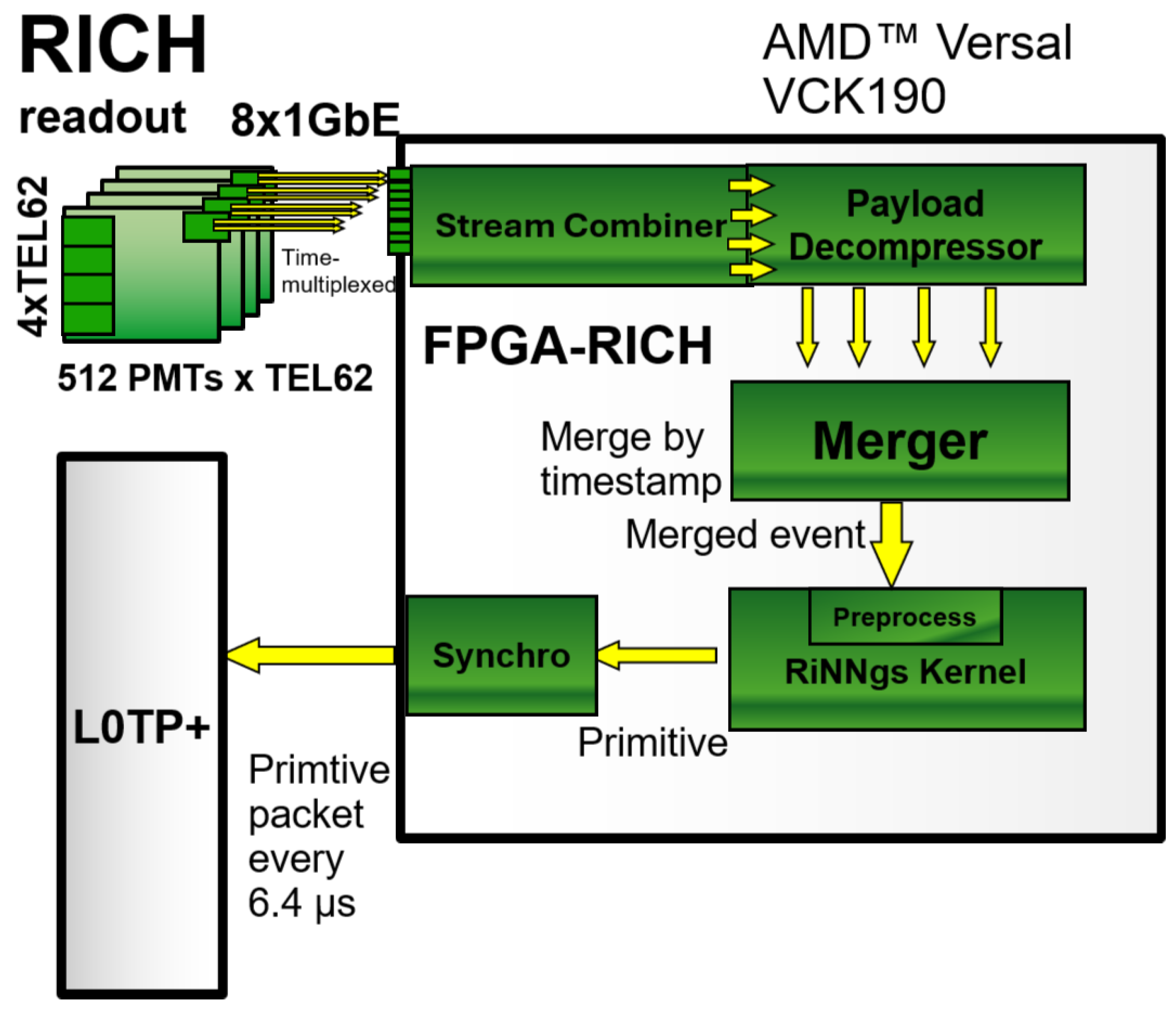
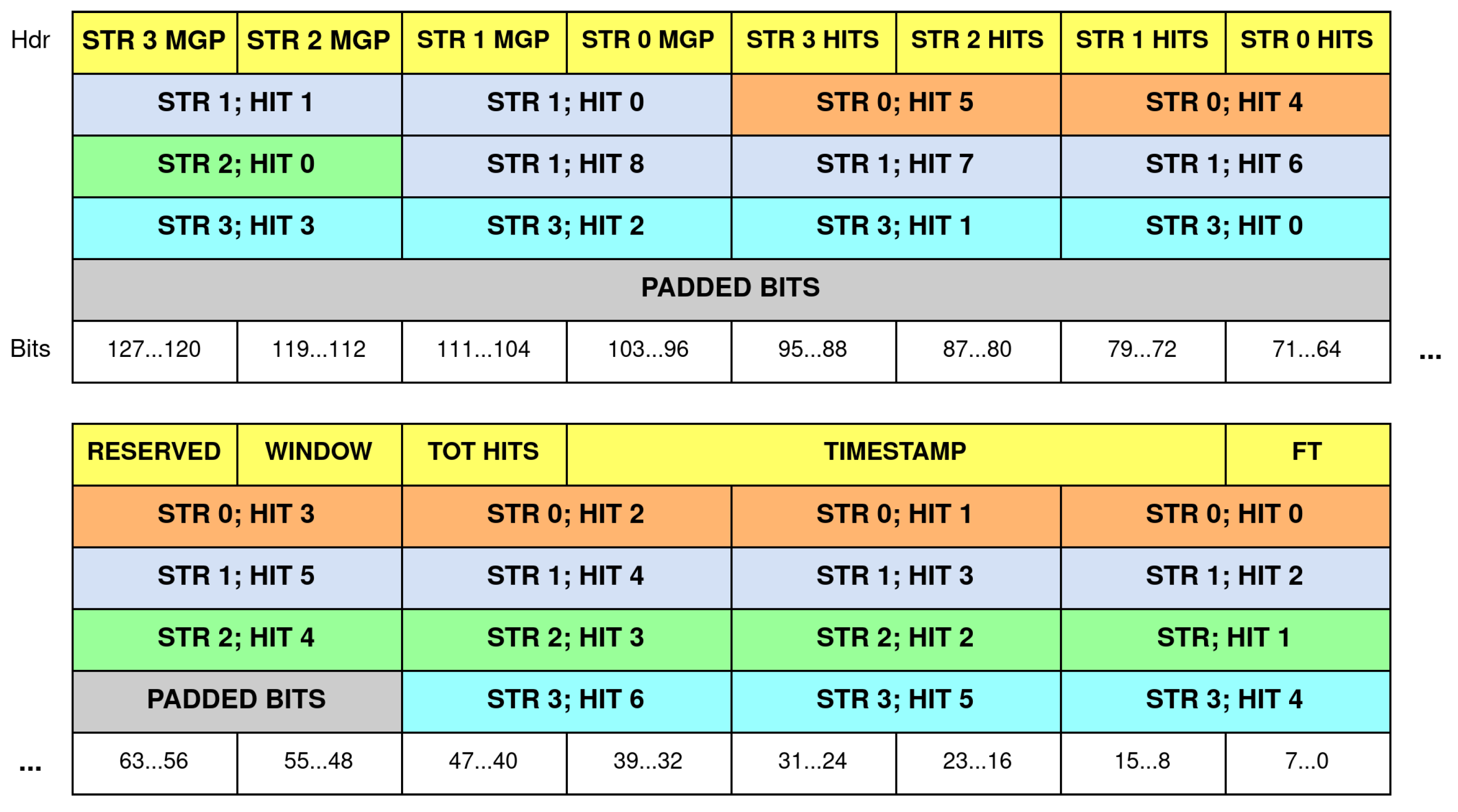
2.1. The FPGA-RICH Streaming Pipeline

The FPGA-RICH methodology is based on a streaming processing pipeline that features a single FPGA device (AMDTM Xilinx Versal VCK190) interfaced upstream with the RICH readout and downstream with L0TP+. A scheme is presented in Figure 6.
The RICH uses four TEL62 data-acquisition boards to handle the readout of its 2048 PMT channels, each board managing 512 PMT channels. Custom firmware is implemented in the TEL62s to provide a dedicated trigger flow to FPGA-RICH, separate from the baseline flow based on the hit-multiplicity mentioned in Section 1: the firmware aims at delivering individual PMT-channels hit-data to FPGA-RICH in a convenient format. The PMT channel hits clustered around a specific timestamp are collected to build an event fragment, and subsequently, multiple event fragments are put into an MGP packet. MGPs are sent out through UDP. Each board sends an MGP packet to FPGA-RICH periodically every 12.8 μ s, beginning with the start-of-burst signal and relying on two 1 GbE ethernet links used with time-multiplexing [9] (alternatively on and off in time). If no event fragments are present, an empty MGP is sent.
Within FPGA-RICH, the first step of the pipeline takes care of combining the two time-multiplexed streams from each board into a single stream, making for four streams in total, one per board. Afterwards, a d e c o m p r e s s o r decodes the MGP packets data encapsulated in the UDP packets payload for each stream, arranging them into separate paths, one for the header—incorporating events timestamp and meta-data information—and one for the events hit-data (64 bits for header and 128 bits for data). Since the event fragments from each board carry only a fourth of the full PMT readout information, they have to be merged to build a complete physics event: a m e r g e r module handles this process. It manages each of the four MGP streams through a FIFO (First In First Out buffer) interface. By construction, each MGP contains a 12.8 μ s window of digitized detector measurements, but each MGP can contain a variable number of events, with different timestamps, and this is true both across the same stream MGPs and across different streams MGPs, simply because of how physics events are distributed in time and in space among the TEL62s (one board might be more active than another), so the merger has to time align the event fragments. The merging process is started after a configurable number of packets are received in the FIFO streams. Merged events are built in the following way: the timestamps of the input events at the head of each stream are compared, and the smallest timestamp is taken as base T b . All other streams events are checked, and if their timestamp T x belongs to a fixed time window W above the base time T b T x T b + W (where W is set at 25 ns), the events are extracted from the FIFOs for merging, and their PMT hit-data are gathered. This process is repeated by extracting events from the streams until timestamps at the head of all four streams are not in the time window. Then, the merged event is complete and it can be streamed out, while the building of the next merged event starts.
The single merged events are produced in a 128-bit format called M2EGP (Multi Merged Event Packet) shown in Figure 7, and are streamed via AXI4-Stream to the kernel implementing the Neural Network, called RiNNgs (Rings Neural Network). The M2EGP format uses a header with timestamp and number of hits information, and multiple data words carrying the PMT hit IDs of the event. Each data word can contain up to 8 PMT hit IDs.
The RiNNgs kernel employs a preprocessing stage to build the input vector for the Neural Network from the stream of 128-bit words composing the M2EGP (as will be described in Section 2.3), then it classifies the event with respect to the number of Cherenkov rings ( N r ) and sends the N r information along with the event timestamp to a s y n c h r o n i z e r . The synchronizer standardizes the FPGA-RICH trigger primitive flow with the L0TP+ protocol, which expects primitives delivered in packets every 6.4 μ s from all sub-detectors. It groups FPGA-RICH primitives into 6.4 μ s windows, sending empty packets when no primitives are present. The synchronizer uses an internal time counter, triggered by the start of burst signal that FPGA-RICH receives from the NA62 common timing, trigger and control (TTC) infrastructure [9] alongside the common 40 MHz clock.

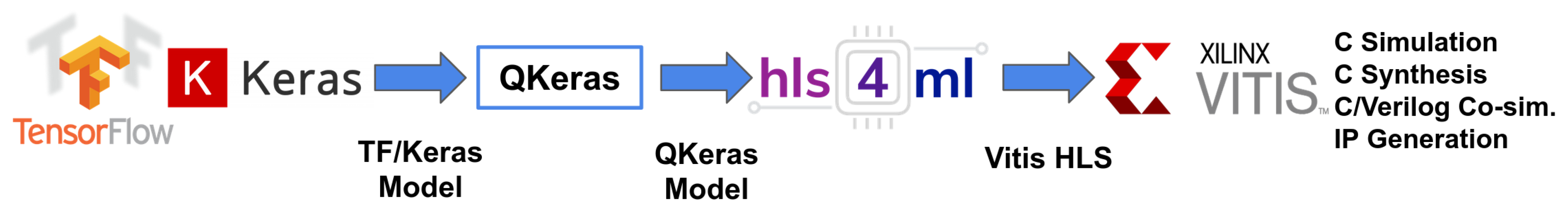
2.2. The Rings Neural Network IP (RiNNgs) Development Workflow

The FPGA-RICH pipeline is described in Hardware Description Language (VHDL), with the exception of the RiNNgs kernel, which relies on a multi-stage, iterative workflow based on High-Level Synthesis (HLS). The HLS programming paradigm allows translation of a high-level description of a design (C++ in our case) into a Register Transfer Level (RTL) hardware description, through the use of a tool (we use XilinxTM Vitis 2022.2) leveraging directives, or pragmas, provided in the high-level code—such as loop unrolling and pipelining—to optimize the generated RTL code. RiNNgs development workflow is schematized in Figure 8.
Here, we describe this workflow at a high level; the details of the Neural Network models implemented with it are provided in Section 2.3.
The open-source machine learning framework Tensorflow, with the Keras API, is used to design the Neural Network model architecture (number and kind of layers) and the input representation and preprocessing, and to define training strategies such as class balancing and hyperparameters tuning (batch size, optimizer choice, learning rate, etc.). Training is performed with full numerical precision (32-bit floating-point) in Keras.
Afterwards, the QKeras python library [19] is used to transform the model layers into a quantized version that uses variable fixed-point precision for the weights, biases and activations, and to train the model in a quantization-aware fashion. The quantization optimizes resource consumption and computational efficiency of the FPGA implementation. Through iterative training runs, the aim is to find the minimal fixed-point data size (and best partitioning between integral and fractional widths) that does not degrade classification performance with respect to the un-quantized Keras model.
After this step, the High-Level Synthesis for Machine Learning (hls4ml v0.7) [20] python library from CERN is used to convert the Neural Network layers defined in QKeras into an HLS implementation. In particular, the hls4ml library implements a series of custom tuneable parameters to configure the Neural Network HLS implementation, in terms of dataflow and resource usage. In terms of dataflow, either a parallel or a streaming implementation can be set (with the I O T y p e parameter), determining the type of data structure used for the Neural Network inputs, intermediate activations between layers, and outputs. In the parallel case, arrays are used, which are typically implemented in RAM and, in principle, can be fully unrolled (implemented on separate RAM units) at the cost of FPGA memory. In the stream case, HLS streams are used, which are a more efficient and scalable mechanism to represent data that are produced and consumed in a sequential manner, and are typically implemented with FIFO buffers instead of RAMs. This is the ideal approach for the online RICH data processing and is what we use for our models.
For what concerns parallelization and resource reuse, hls4ml offers a R e u s e F a c t o r parameter that configures how often a particular hardware resource (like a multiplier) is reused during computation. Low R e u s e F a c t o r means more dedicated resources for independent computations, for a typically faster but resource-consuming implementation. In this context (in hls4ml v0.7), an optimization parameter called S t r a t e g y can be set to either L a t e n c y to optimize for latency and maximum parallelization, or R e s o u r c e , which assumes a ReuseFactor higher than one and uses less parallelization.
The final workflow step is the synthesis of the HLS model into an FPGA bitstream through the Xilinx Vivado tool (v2022.2). For verification of the HLS model classification performance, the emulation offered by hls4ml, which is a bit-accurate software simulation of the design, is used, while for verification of the model performance in terms of throughput, latency and resource consumption, the estimates provided by the Vivado C/RTL co-simulation, which is a simulation of the RTL generated by HLS that uses a C testbench as stimuli, are used.
Throughout all the steps described above, the design targets of Neural Network classification accuracy, throughput, latency and FPGA resource usage have to be verified. The key challenge for our work is managing the 10 MHz event throughput of NA62, which restricts the RiNNgs Neural Network to an Initiation Interval ( I I )—in HLS terminology, the number of clock cycles required between the beginning of an algorithm’s processing on one data sample and the beginning on the following data sample. Assuming a reference clock of 150 MHz, this corresponds to an upper limit of 15 cycles. This limits the complexity of the Neural Network models that can be deployed with a single FPGA as a target, given the existing trade-off between model size, I I , and FPGA resources consumption. In particular, for our system, we test fully connected and Convolutional Neural Network models. In fully connected ( f c ) networks, a layer’s computation consists of the i n p u t - v e c t o r × w e i g h t - m a t r i x multiplication, requiring M l × N l = d l multiply–accumulate operations, where M l and N l are the input and output dimensions of layer l. Since multiple layers are implemented as stages of a pipeline, the I I is ultimately limited by the layer with the largest I I and thus d l . The R e s o u r c e F a c t o r can be configured to employ multiple multiplier units in parallel and improve I I but at the cost of many resources if the layers are large. For two-dimensional Convolutional Neural Network ( C N N ) layers, the streaming implementation made by hls4ml (version 0.7) [21] relies on a stream to process the input layer feature map of h e i g h t × w i d t h × c h a n n e l s = H × W × C . Each item of the stream is an array of size C, so there are actually H W items that are streamed to the layer, one per clock cycle. This sequential processing is optimized to reach ∼1 μ s latency [21] and to consume few FPGA memory resources, as it does not build and keep in memory the whole input–tensor matrix and kernel–weight matrix to perform matrix multiplication as is typically done in general matrix multiplication algorithms [22] but only buffers temporarily in FIFOs the input items that need to be reused while the convolutional sliding window moves through the feature map. However, in the hls4ml version that we use, it costs at least H W clock cycles in terms of I I since a whole input feature map has to be streamed item by item (or pixel by pixel for single channel images), before the next feature map can be processed.

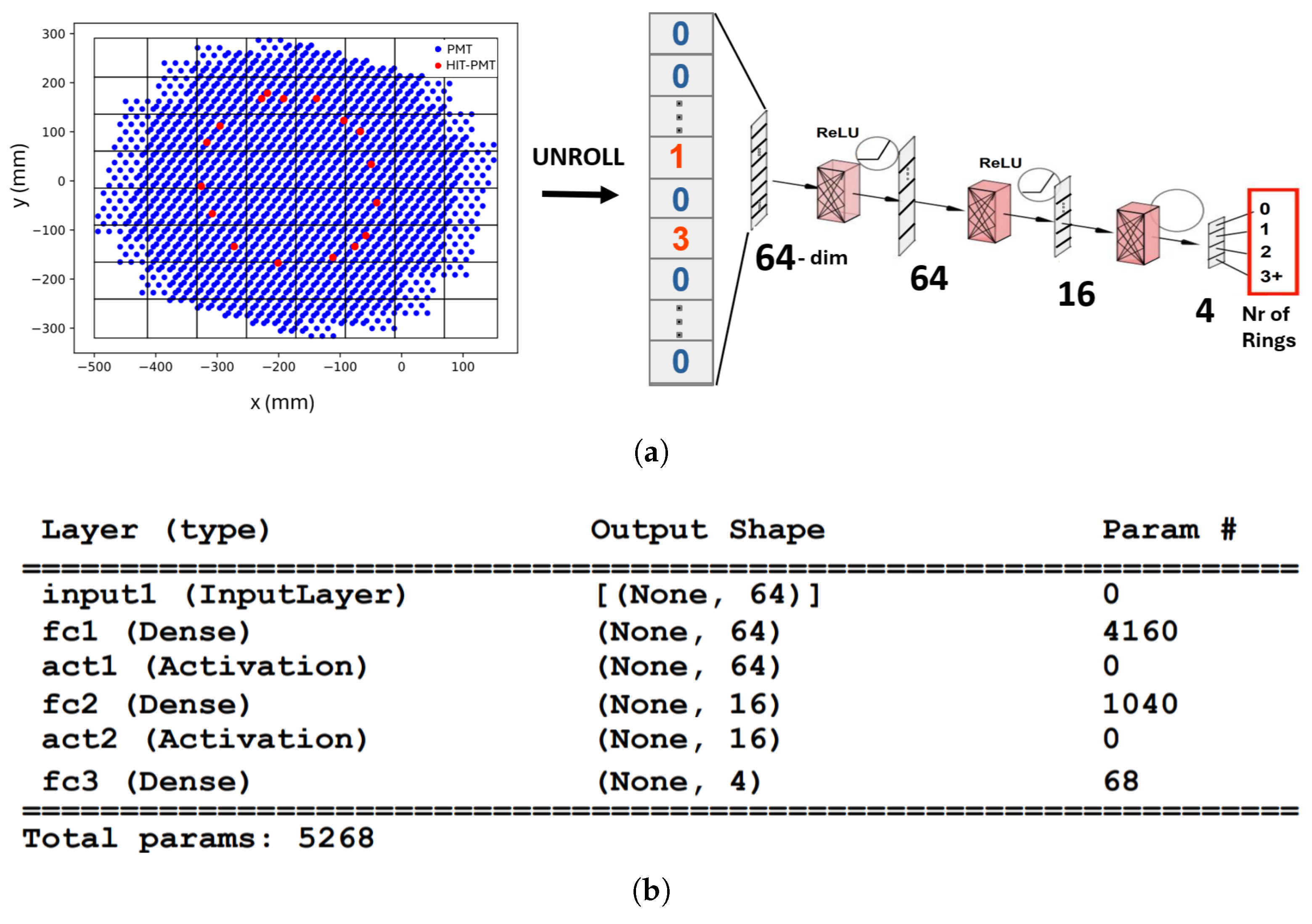
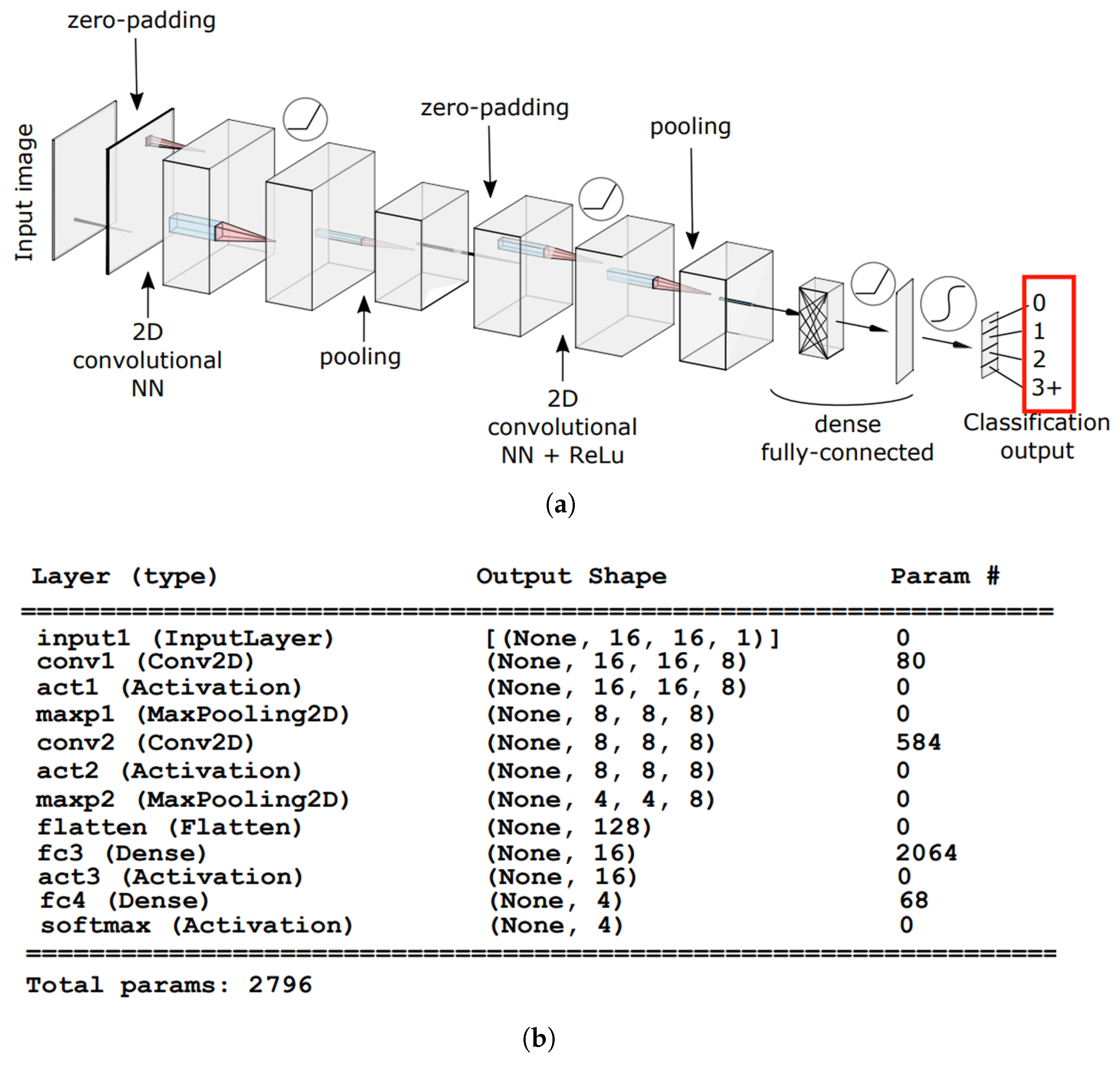
2.3. The RiNNgs Neural Network Models Architecture

We test different variants for the RiNNgs model architecture that we call 8×8- f c , 16×16- f c , and 16×16- C N N .
The 8×8- f c model is illustrated in Figure 9: it is composed of 3 fully connected layers with, respectively, 64, 16, and 4 output neurons. The first two layers are activated by ReLu functions, while a simple argmax is applied after the last layer. The event is classified in one of four N r classes for 0, 1, 2, or 3 or more rings.
The 64-dimensional linear input is obtained from the preprocessing procedure illustrated in Figure 9: the RICH disk plane containing the PMTs is treated similarly to an image and discretized into 8 × 8 cells or bins containing a variable number of PMTs, the maximum number of PMTs in the most populated cell being 55. A look-up table is used to map each hit-PMT ID in an event to a cell, and the 64-dimensional input to the NN is obtained by “unrolling” the discretized image into a linear vector, where each cell contains the number of hit PMTs in that cell; on average, only ∼2–3 PMT-hits are found in a hit cell. After NN quantization, we use 6 integer bits for the input representation, <8,1> fixed-point representation for the weights and biases of all layers, and <16,5> for activations. Given the pair <x,y>, x is the size in bits of the integer part, and y is the same quantity for the fractional part of the fixed-point number of size x+y bits. The S t r a t e g y parameter of the hls4ml library is set to L a t e n c y , the R e u s e F a c t o r parameter is set to 8, and the I O t y p e parameter is set to S t r e a m i n g .
The 16×16- f c model is a variant of the 8×8- f c model that uses a finer 16 × 16 grid for the input preprocessing stage. The input layer size thus grows to 16 × 16 = 256 . To keep the I I below 15 clock cycles at 150 MHz, the first layer has to be reduced compared to the 8×8- f c variant, from size 64 to size 32, and the R e u s e F a c t o r has to be halved to 4.
The 16×16- C N N model architecture is illustrated in Figure 10.
It is a compact model using two convolutional layers ( f i l t e r s = 8 , k e r n e l s i z e = 3 ) with ReLU and Max Pooling ( p o o l s i z e = 2 , s t r i d e = 2 ), and two fully connected layers from 128 to 16 and from 16 to 4. Similarly to the 16×16- f c model case, the input preprocessing involves the creation of a compressed image of size 16×16, but in this case, the image is not unrolled before being input to the NN. Example images are shown in Figure 11. The quantization uses <8,1> fixed-point representation for the weights and biases and <16,6> for input and activations. The S t r a t e g y parameter is set to L a t e n c y , the R e u s e F a c t o r is set to 1, and the I O t y p e is set to S t r e a m i n g .
As described above, all three model variants require a similar preprocessing stage to build the NN input from the PMT hits. This preprocessing stage (called ’imagify’) has to be implemented in hardware to integrate the RiNNgs kernel inside the FPGA-RICH pipeline, where it receives the hits through the stream of M2EGP words. It is written in HLS and works as a simple state machine, processing one word of the M2EGP packet at a time. In the first state, it reads an M2EGP header from the stream, and it extracts the total number of hits in the event and computes the total number of M2EGP data words that it has to process (each data word contains up to 8 hits). Then, in the second state, it receives the data words from the stream: for each one, it reads in parallel all the PMT ID hits and maps them to a corresponding position of the NN input array, using the look-up table that is obtained from the PMT disk plane discretization procedure in Python (v. 3.8.12) and is now synthesized on the FPGA internal memory. When it is finished processing all data words, the state machine goes back to the previous stage, waiting for the next header.

2.4. Functional and Performance Validation Methodology of the Full FPGA-RICH Pipeline

To perform functional validation and a preliminary assessment of the throughput performance of the FPGA-RICH pipeline in the laboratory, we developed a firmware for a separate FPGA board sporting four 1GbE ports to deliver synthetic data to FPGA-RICH over ethernet: stored event data packets (MGPs) are sent over four links every 12.8 μ s, emulating the timing and protocol of the TEL62 streams. Then, for the full validation of the system, FPGA-RICH is integrated in parasitic mode (i.e., without affecting the standard experiment data-taking) with the RICH readout at NA62.

3. Results

The performance of the three RiNNgs model variants described above is presented in Table 1, in terms of e f f i c i e n c y (or r e c a l l = T r u e P o s i t i v e s T r u e P o s i t i v e s + F a l s e N e g a t i v e s ) and p u r i t y (or p r e c i s i o n = T r u e P o s i t i v e s T r u e P o s i t i v e s + F a l s e P o s i t i v e s ) of the classification for the different N r classes obtained on the 3.5 million events test dataset, averaged over five training runs.
The table reports the performance of the quantized QKeras version of the models. We do not notice a significant difference with the performance of the HLS software emulated version as can be seen in Figure 12, which shows inference performance of the 8×8- f c architecture on the test dataset with the Receiver Operating Characteristic (ROC) curves for the different precision versions of the model: 32-bit Keras, quantized QKeras, and the bit-accurate software emulation of the quantized HLS version provided by hls4ml.
Table 2 presents FPGA resources utilization, I I , and latency for the different model variants after synthesis.
Table 1 and Table 2 show that the finer grid of the 16×16- f c variant does not help the network learn significantly better than the 8×8- f c variant, while the cost difference in terms of FPGA resources and I I is significant. The 16×16- C N N variant is light on resources but requires a very large number of I I cycles ( I I = 369 , throughput 0.7 MHz) by nature of the previously described hls4ml streaming implementation requiring at least one clock cycle per pixel. It has to be noted that the latest versions of the hls4ml package (v 0.8.1+) have introduced an updated streaming implementation for convolutional layers, allowing a larger portion of the input image (related to the convolutional kernel size) to be processed per clock cycle. Adopting this feature in future FPGA-RICH models could improve I I performance, though it is unlikely that the I I of fully connected models could be matched.
For the current FPGA-RICH implementation, we choose to prioritize the advantage of low I I granted by the 8×8- f c version, whose classification performance ( e f f i c i e n c y 83 % and p u r i t y 85 % on the four classes average) is satisfactory for L0TP+ masks, and can be further adjusted to favor purity or efficiency where it best suits the trigger selectivity strategy, using the ROC curves and changing classification thresholds.
The I I values reported in Table 2 are relative to the Neural Network algorithm that starts when an input vector is received and do not include the preprocessing stage. Since this stage operates on the M2EGP words which can contain 8 PMT hits at most, and it takes one clock cycle to read a word, the I I of this stage is variable and it depends on the number of hits in the event. We measure an II = 2–15 cycles at 150 MHz clock (throughput = 75–10 MHz), where 15 cycles are required for an extremely unlikely scenario where the events received contain 13 words (97-104 PMT hits). For average NA62 events with 3 words (∼18 hits, see Figure 5), the I I of the preprocessing stage is equal to 3 cycles, so it does not compromise throughput and the Neural Network stage is the bottleneck with its 5 cycles, which correspond to a 30 MHz throughput. This is comfortably above the L0 10 MHz requirement, so the RiNNgs stage of the FPGA-RICH pipeline satisfies the throughput.

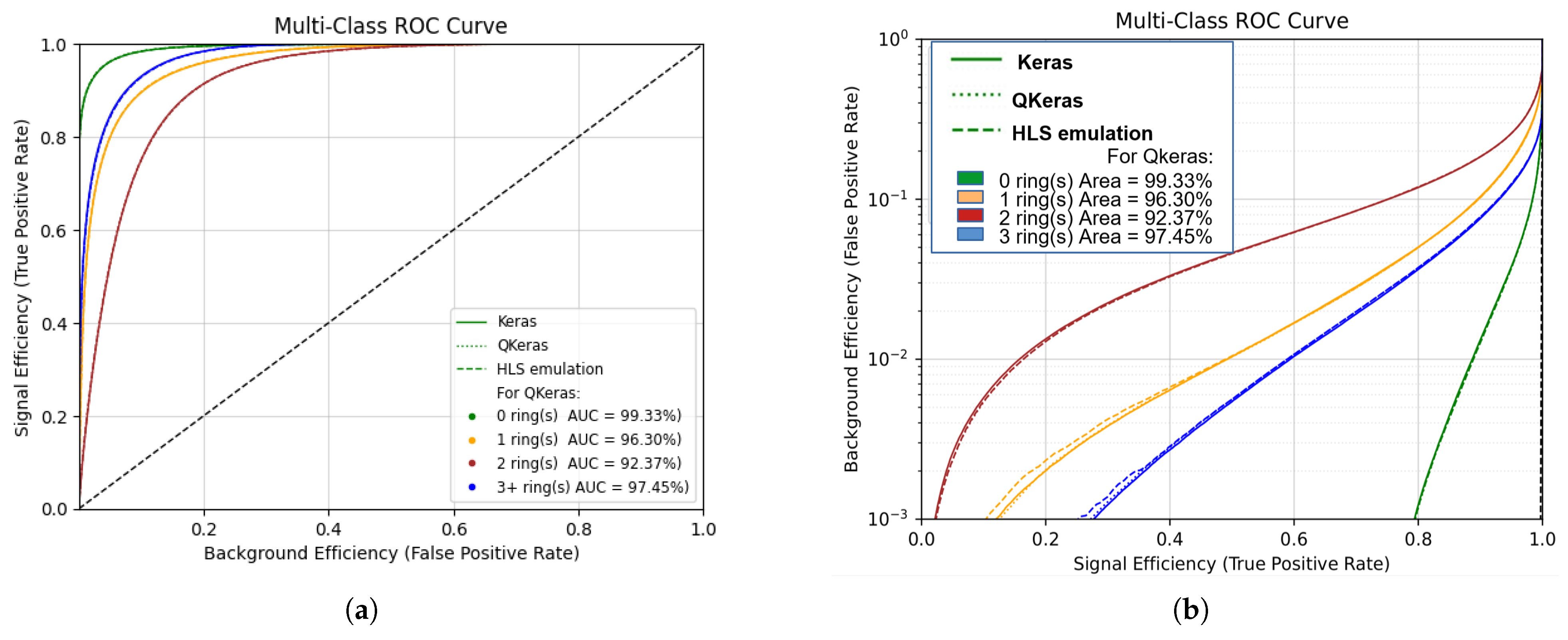
The Validation of the Full FPGA-RICH Pipeline

The full FPGA-RICH pipeline integrating the 8×8- f c variant of the NN is synthesized with a 150 MHz clock. The resource usage is LUT = 127, 777 (14.2%), Flip-Flop = 107, 981 (6.0%), DSP = 146 (7.4%), and BRAM = 25 (2.6%).
The pipeline is tested with synthetic MGP packets, in input to FPGA-RICH every 12.8 μ s from four streams, emulating the TEL62s of the RICH readout. In this scenario, the effective event throughput seen by FPGA-RICH can be controlled by setting the number of events in a packet on the sender side. However, a realistic timing structure depends also on how many and how the events hits are split across the different TEL62s streams and how well their timestamps are aligned. In particular, these parameters affect the throughput performance of the FPGA-RICH m e r g e r , which has a budget of ∼2000 clock cycles at 150 MHz to perform the merging of the events inside the four streams’ packets. The cycles spent increase if there are more hits in an event but also if the hits are less distributed among streams since this reduces the amount of parallelization achievable in the merging operation. Reproducing the exact experimental pattern of MGP packets is challenging, but we use the artificially controlled setup to estimate a bottom limit on achieved throughput of 9.375 MHz under the following test scenario: 120 events time aligned across the streams and carrying a total of 18 hits (average-event hits number) balanced across the streams. More stringent tests with this simple packet structure, just adding events, are limited by the 1500 bytes cap on the ethernet frame size that the system uses.
For what concerns the latency of the full pipeline, a measurement is obtained with the Vivado Integrated Logic Analyzer, and it is well within the ∼1 μ s target: the time from the first set of events input to the d e c o m p r e s s o r to the time of the first RiNNgs-primitive input to the synchronizer is ≈900 ns, to which a variable component has to be added since the s y n c h r o n i z e r sends out a packet of primitives every 6.4 μ s.
Rather than pushing in the synthetic data direction, we have decided to finalize validation directly on real data by integrating FPGA-RICH with the RICH readout in parasitic mode. In parallel, we complete a synthesis of the full pipeline at 300 MHz clock, which if needed will increase the m e r g e r effective clock cycles budget. The pipeline is currently under validation at the experiment. It is tested during NA62 Run 2 (in 2024). It collects data successfully for about a fourth of the ∼5 s periodic data collection window of the experiment (the burst), after which it overflows because of a leftover issue related not to the pipeline itself but to the custom TEL62 firmware: corrupted MGP packets with misaligned timestamps among the four TEL62 streams are created, and this increases the effective throughput seen by the m e r g e r above 10 MHz because same-time events that should be merged show up as separate events.
The solution of adjusting the TEL62 firmware while the experiment is taking data is not ideal, but development is undergoing to work around the issue downstream at the FPGA-RICH level by flushing corrupted events. This will allow us to keep up with the throughput at the cost of some event-classification accuracy.

4. Discussion

We have developed FPGA-RICH, an FPGA-based system designed to implement real-time AI-based partial particle identification within the strict latency and throughput constraints of the NA62 low-level trigger system. The system combines traditional data processing techniques with modern machine learning approaches, classifying events by number of charged particles with performance suitable for trigger selectivity improvement, while maintaining the required 10 MHz throughput and 1 μ s scale latency. The use of High-Level Synthesis allows for relatively easy reprogrammability, which has been beneficial for development in iteratively testing different Neural Network solutions, and will be beneficial as the system impact on trigger efficiency is evaluated and which will possibly motivate adjustments.
This work shows the effectiveness and maturity of modern programming paradigms and machine learning algorithms even within the challenging context of High Energy Physics experiments’ online data acquisition and analysis. As a future step, we envision the transfer of the current implementation of FPGA-RICH from an independent FPGA device to the one hosting L0TP+ itself. L0TP+ is deployed on a Xilinx VCU118 board, using only a small fraction of FPGA resources (30% BRAM, 20% of LUT , 1% DSP). Furthermore, the board setup sports a consistent number of available high-speed links [23]. This scheme of integration allows a direction for development, where we collect primitive data from other NA62 sub-detectors at L0TP+ level, for instance energy from the calorimeter, and use it to produce even more refined physics trigger primitives at L0, such as the number of electrons, highlighting the versatility granted by the input–output and logic re-programmability of an FPGA-based Trigger and Data Acquisition system and how it can allow elaborate data analysis pipelines at the lowest hardware level.

Author Contributions

Conceptualization, A.L., P.V., P.C., R.A., O.F., L.P., M.T. and A.C.; methodology, A.L., L.P., P.C., M.T., C.R., P.P. and A.C.; Hardware block design: R.A., A.B., P.C., O.F., F.L.C. and P.V.; software, M.T., P.C., P.P., C.R., L.P., A.C. and M.M.; validation, P.P., M.T., P.C., A.L., A.B., L.P., P.V. and C.C.; Formal analysis: A.C., A.L., P.P., L.P., M.T. and C.R.; data curation, M.T. and R.P.; writing—original draft preparation, P.P.; writing—review and editing, A.L., L.P., C.R., A.C., R.P., R.A., F.S. and O.F.; supervision, A.L.; project administration, A.L. and M.R.; funding acquisition, A.L., P.V. and M.R. All authors have read and agreed to the published version of the manuscript.

Funding

This research was founded by INFN Scientific Committees 1 (NA62 experiment) and 5 (APEIRON experiment), by the EuroHPC-JU TEXTAROSSA project G.A. n.956831, and by Italian PNRR MUR project CUPI53C22001400006-FAIR (funded by NextGenerationEU).

Data Availability Statement

A reduced set of the original data presented in this study, along with the software described, are openly available at https://baltig.infn.it/ape-lab/fpgarich.git, accessed on 4 May 2025. The full dataset is available upon reasonable request, due to the NA62 experiment-data-sharing policy.

Acknowledgments

Pierpaolo Perticaroli is a PhD student enrolled in the National PhD program in Artificial Intelligence, XXXIX cycle, course on Health and life sciences, organized by Università Campus Bio-Medico di Roma. This article is a revised and expanded version of a paper entitled FPGA-RICH: A low-latency, high-throughput online particle identification system for the NA62 experiment [24], which was presented at Conference on Computing in High Energy and Nuclear Physics (CHEP2024), in the AGH University of Kraków, Institute of Nuclear Physics Polish Academy of Sciences and Jagiellonian University, 19–25 October 2024.

Conflicts of Interest

The authors declare no conflicts of interest.

Abbreviations

The following abbreviations are used in this manuscript:
FPGAField Programmable Gate Array
RICHRing Imaging Cherenkov Detector
L0TPLevel 0 Trigger Processor
TDAQTrigger and Data Acquisition
HLSHigh-Level Synthesis
NNNeural Network
PMTPhoto-Multiplier Tube
CNNConvolutional Neural Network
FCFully Connected
RiNNgsRings Neural Network
MGPMulti-event GPU Packet
M2EGPMulti Merged Event Packet

References

  1. Gil, E.C.; Albarrán, E.M.; Minucci, E.; Nüssle, G.; Padolski, S.; Petrov, P.; Szilasi, N.; Velghe, B.; Georgiev, G.; Kozhuharov, V.; et al. The beam and detector of the NA62 experiment at CERN. J. Instrum. 2017, 12, P05025. [Google Scholar] [CrossRef]
  2. Cortina Gil, E.; Jerhot, J.; Lurkin, N.; Numao, T.; Velghe, B.; Wong, V.W.S.; Bryman, D.; Hives, Z.; Husek, T.; Kampf, K.; et al. Observation of the K+π+ν ν ¯ decay and measurement of its branching ratio. J. High Energy Phys. 2025, 2025. [Google Scholar] [CrossRef]
  3. Cortina Gil, E.; Kleimenova, A.; Minucci, E.; Padolski, S.; Petrov, P.; Shaikhiev, A.; Volpe, R.; Numao, T.; Petrov, Y.; Velghe, B.; et al. Performance of the NA62 trigger system. JHEP 2023, 03, 122. [Google Scholar] [CrossRef]
  4. Ammendola, R.; Biagioni, A.; Ciardiello, A.; Cretaro, P.; Frezza, O.; Lamanna, G.; Lo Cicero, F.; Lonardo, A.; Martinelli, M.; Piandani, R.; et al. Progress report on the online processing upgrade at the NA62 experiment. J. Instrum. 2022, 17, C04002. [Google Scholar] [CrossRef]
  5. Anzivino, G.; Barbanera, M.; Bizzeti, A.; Brizioli, F.; Bucci, F.; Cassese, A.; Cenci, P.; Ciaranfi, R.; Duk, V.; Engelfried, J.; et al. Light detection system and time resolution of the NA62 RICH. J. Instrum. 2020, 15, P10025. [Google Scholar] [CrossRef]
  6. Anghinolfi, F.; Jarron, P.; Krummenacher, F.; Usenko, E.; Williams, M. NINO, an ultra-fast, low-power, front-end amplifier discriminator for the Time-Of-Flight detector in ALICE experiment. In Proceedings of the 2003 IEEE Nuclear Science Symposium. Conference Record (IEEE Cat. No.03CH37515), Portland, OR, USA, 19–25 October 2003; Volume 1, pp. 375–379. [Google Scholar] [CrossRef]
  7. Spinella, F.; Angelucci, B.; Lamanna, G.; Minuti, M.; Pedreschi, E.; Pinzino, J.; Piandani, R.; Sozzi, M.; Venditti, S. The TEL62: A real-time board for the NA62 Trigger and Data AcQuisition. Data flow and firmware design. In Proceedings of the 2014 19th IEEE-NPSS Real Time Conference, Nara, Japan, 26–30 May 2014; pp. 1–2. [Google Scholar] [CrossRef]
  8. Christiansen, J. HPTDC High Performance Time to Digital Converter, Technical report; Version 2.2 for HPTDC version 1.3.; CERN: Geneva, Switzerland, 2004. [Google Scholar]
  9. Ammendola, R.; Angelucci, B.; Barbanera, M.; Biagioni, A.; Cerny, V.; Checcucci, B.; Fantechi, R.; Gonnella, F.; Koval, M.; Krivda, M.; et al. The integrated low-level trigger and readout system of the CERN NA62 experiment. Nucl. Instruments Methods Phys. Res. Sect. A Accel. Spectrometers Detect. Assoc. Equip. 2019, 929, 1–22. [Google Scholar] [CrossRef]
  10. Cretaro, P.; Biagioni, A.; Frezza, O.; Cicero, F.L.; Lonardo, A.; Martinelli, M.; Paolucci, P.S.; Pontisso, L.; Simula, F.; Vicini, P.; et al. NaNet: A Reconfigurable PCIe Network Interface Card Architecture for Real-time Distributed Heterogeneous Stream Processing in the NA62 Low Level Trigger. PoS 2019, TWEPP2018, 118. [Google Scholar] [CrossRef]
  11. Nottbeck, N.; Schmitt, D.C.; Büscher, P.D.V. Implementation of high-performance, sub-microsecond deep neural networks on FPGAs for trigger applications. J. Instrum. 2019, 14, P09014. [Google Scholar] [CrossRef]
  12. Iiyama, Y.; Cerminara, G.; Gupta, A.; Kieseler, J.; Loncar, V.; Pierini, M.; Qasim, S.R.; Rieger, M.; Summers, S.; Van Onsem, G.; et al. Distance-Weighted Graph Neural Networks on FPGAs for Real-Time Particle Reconstruction in High Energy Physics. Front. Big Data 2021, 3, 598927. [Google Scholar] [CrossRef] [PubMed]
  13. Bortolato, G.; Cepeda, M.; Heikkilä, J.; Huber, B.; Leutgeb, E.; Rabady, D.; Sakulin, H.; on behalf of the CMS collaboration. Design and implementation of neural network based conditions for the CMS Level-1 Global Trigger upgrade for the HL-LHC. J. Instrum. 2024, 19, C03019. [Google Scholar] [CrossRef]
  14. Migliorini, M.; Pazzini, J.; Triossi, A.; Zanetti, M.; Zucchetta, A. Muon trigger with fast Neural Networks on FPGA, a demonstrator. J. Phys. Conf. Ser. 2022, 2374, 012099. [Google Scholar] [CrossRef]
  15. Govorkova, E.; Puljak, E.; Aarrestad, T.; James, T.; Loncar, V.; Pierini, M.; Pol, A.A.; Ghielmetti, N.; Graczyk, M.; Summers, S.; et al. Autoencoders on field-programmable gate arrays for real-time, unsupervised new physics detection at 40 MHz at the Large Hadron Collider. Autoencoders on FPGAs for real-time, unsupervised new physics detection at 40 MHz at the Large Hadron Collider. Nat. Mach. Intell. 2022, 4, 154–161. [Google Scholar] [CrossRef]
  16. Aberle, O.; Béjar Alonso, I.; Brüning, O.; Fessia, P.; Rossi, L.; Tavian, L.; Zerlauth, M.; Adorisio, C.; Adraktas, A.; Ady, M.; et al. High-Luminosity Large Hadron Collider (HL-LHC): Technical Design Report; CERN Yellow Reports: Monographs; CERN: Geneva, Switzerland, 2020. [Google Scholar] [CrossRef]
  17. Peters, A.; Sindrilaru, E.; Adde, G. EOS as the present and future solution for data storage at CERN. J. Phys. Conf. Ser. 2015, 664, 042042. [Google Scholar] [CrossRef]
  18. NA62 Collaboration. 2017 NA62 Status Report to the CERN SPSC; Technical report; CERN: Geneva, Switzerland, 2017. [Google Scholar]
  19. Coelho, C.N.; Kuusela, A.; Li, S.; Zhuang, H.; Ngadiuba, J.; Aarrestad, T.K.; Loncar, V.; Pierini, M.; Pol, A.A.; Summers, S. Automatic heterogeneous quantization of deep neural networks for low-latency inference on the edge for particle detectors. Nat. Mach. Intell. 2021, 3, 675–686. [Google Scholar] [CrossRef]
  20. Duarte, J.; Han, S.; Harris, P.; Jindariani, S.; Kreinar, E.; Kreis, B.; Ngadiuba, J.; Pierini, M.; Rivera, R.; Tran, N.; et al. Fast inference of deep neural networks in FPGAs for particle physics. JINST 2018, 13, P07027. [Google Scholar] [CrossRef]
  21. Aarrestad, T.; Loncar, V.; Ghielmetti, N.; Pierini, M.; Summers, S.; Ngadiuba, J.; Petersson, C.; Linander, H.; Iiyama, Y.; Di Guglielmo, G.; et al. Fast convolutional neural networks on FPGAs with hls4ml. Mach. Learn. Sci. Technol. 2021, 2, 045015. [Google Scholar] [CrossRef]
  22. Vasudevan, A.; Anderson, A.; Gregg, D. Parallel Multi Channel convolution using General Matrix Multiplication. In Proceedings of the 2017 IEEE 28th International Conference on Application-specific Systems, Architectures and Processors (ASAP), Seattle, WA, USA, 10–12 July 2017; pp. 19–24. [Google Scholar] [CrossRef]
  23. Ammendola, R.; Biagioni, A.; Chiarini, C.; Cretaro, P.; Frezza, O.; Lo Cicero, F.; Lonardo, A.; Martinelli, M.; Perticaroli, P.; Piandani, R.; et al. The new hardware trigger processor at NA62 experiment: Status of the System and First Results. In Proceedings of the 27th Conference on Computing in High Energy and Nuclear Physics (CHEP 2024), Krakow, Poland, 21–25 October 2024. [Google Scholar]
  24. Perticaroli, P.; Ammendola, R.; Biagioni, A.; Chiarini, C.; Ciardiello, A.; Cretaro, P.; Frezza, O.; Lo Cicero, F.; Martinelli, M.; Piandani, R.; et al. FPGA-RICH: A low-latency, high-throughput online particle identification system for the NA62 experiment. In Proceedings of the 27th Conference on Computing in High Energy and Nuclear Physics (CHEP 2024), Krakow, Poland, 19–25 October 2024. [Google Scholar]
Figure 1. (a) The NA62 Ring Imaging Cherenkov detector. The Cherenkov light cones produced by charged particles crossing the neon in the vessel are reflected by a mirror mosaic onto two disks placed on the upstream side of the detector. Each disk houses 976 PMTs. Image from reference [1]. (b) An example RICH event with three charged particles.
Electronics 14 01892 g001
Figure 2. The placement of FPGA-RICH within the NA62 Trigger and Data Acquisition system, with its new stream of primitives.
Electronics 14 01892 g002
Figure 3. Multi-event MGP format above, with the “Event data” field expanded below. The ID in “HIT PM ID” uses a simple encoding: the real PMT ID (integer 0 to 2047) can be obtained concatenating the 9 bit-field (counting 0 to 511) to the “SOURCE SUB-ID” of the MGP header, which indicates the readout board number (0, 1, 2 or 3) that sent the event fragment.
Electronics 14 01892 g003
Figure 4. Example of an event from a file extracted from the NA62 reconstruction framework. The first two columns of each row are the timestamp and the burst ID of the event (the burst is a periodic window lasting ∼5 s when accelerated particles are made to collide and the detector is active), while the third is a generic event ID given by the reconstruction method. In the fourth column, there is a tag defining the information contained in the rest of each line: (tag 20) summary of the parameters of a reconstructed ring, such as the coordinates of the center (sixth and seventh columns), the ring radius (eighth column), the likelihood (ninth column), the number of PMTs used for the reconstruction (tenth column) and their list of IDs (from column eleven onward), obtained by the DownstreamTrack reconstruction algorithm; (tag 40) direction and module of the momentum of the track reconstructed in NA62 spectrometer; (tag 50, tag 60, tag 30) other physics information; (tag 21) same information as tag 20, but for a RICHRECO reconstructed ring; (tag 22) summary of the parameters coming from the DownstreamTrack method, like the number of rings reconstructed (fifth column); (23) summary of the parameters coming from the RichReco method, like the number of rings reconstructed (fifth column) plus the number of hit PMTs in the event (tenth column) and their list of IDs (from column eleven onward). In this example, the event DownstreamTrack identifies only one ring, while RichReco identifies two.
Electronics 14 01892 g004
Figure 5. Distributions on the 3.13 million events training dataset: left, number of PMT hits per event; right, number of rings from the offline trackless reconstruction algorithm (RICHRECO).
Electronics 14 01892 g005
Figure 6. Scheme of the FPGA-RICH pipeline integrated with the RICH readout and L0TP+.
Electronics 14 01892 g006
Figure 7. The M2EGP (Multi Merged Event Packet) data format. It represents a single event as it comes streamed in input to the Neural Network kernel. The header contains the timestamp (which has a resolution of 25 ns) and finetime (FT, which allows a maximum resolution of 100 ps) of the event and some metadata information; the following words carry the PMT Hit IDs of the event, at most 8 per word. STR i indicates that prior to the merging, the hit belonged to the i-th readout board stream.
Electronics 14 01892 g007
Figure 8. Software to hardware codesign workflow for the Rings Neural Network (RiNNgs) IP.
Electronics 14 01892 g008
Figure 9. (a) Scheme of the architecture and preprocessing of the 8×8- f c model. The RICH disk plane is discretized in 8×8 cells. The value in each cell is the number of hit PMTs in the cell. The 64 values obtained are used as input for the f c model (b) Layer specification in Keras and parameters of the 8×8- f c model. The Output Shape column indicates the (Batch size, Output size) of each layer (the Batch size is unspecified at model definition). The Activation layers are Rectified Linear Unit (ReLU) layers.
Electronics 14 01892 g009
Figure 10. (a) Scheme of the architecture of the 16×16- C N N model. (b) Layers specification in Keras and parameters of the 16×16- C N N model. The Output Shape column indicates the (Batch size, Image x-dim size, Image y-dim size, Number of channels) in output to each layer. Activation layers are ReLUs, except for the Softmax layer at the end. The two Conv2D layers use filters = 8, kernel_size = 3 and padding = same. The MaxPooling layers use pool_size = 2, stride = 2 and padding = same.
Electronics 14 01892 g010
Figure 11. Examples of 16×16 images generated in the preprocessing stage in the 16×16- C N N model with 0, 1, and 2 rings.
Electronics 14 01892 g011
Figure 12. ROC curves for the 8×8- f c model. The different colors refer to different number-of-rings classes, while the different line styles refer to different precision versions for the model: the 32-bit Keras version, the quantized QKeras version, and a software emulation of the quantized HLS version provided by hls4ml. The area under curve refers to the QKeras version. (a) The standard ROC-curves visualization. (b) A semi log-scale visualization with inverted axes of the same ROC curves, which best highlights the minimal separation between the different precision versions of the model.
Electronics 14 01892 g012
Table 1. Classification performance (%) of different RiNNgs Neural Network model variants, for the quantized versions.
Efficiency8×8- fc 16×16- fc 16×16- CNN
0 ring(s) 88.88 ± 0.28 88.86 ± 0.10 88.40 ± 0.25
1 ring(s) 88.90 ± 0.24 88.94 ± 0.24 88.53 ± 0.22
2 ring(s) 76.34 ± 0.87 77.82 ± 0.64 78.31 ± 0.43
3+ ring(s) 77.12 ± 0.55 77.06 ± 0.76 74.29 ± 0.58
Purity8×8- fc 16×16- fc 16×16- CNN
0 ring(s) 95.04 ± 0.23 94.92 ± 0.16 95.42 ± 0.26
1 ring(s) 86.48 ± 0.24 87.22 ± 0.19 87.30 ± 0.25
2 ring(s) 72.22 ± 0.35 72.66 ± 0.41 70.34 ± 0.33
3+ ring(s) 84.62 ± 0.41 84.94 ± 0.42 85.10 ± 0.36
Table 2. Performance and utilization * after synthesis of the RiNNgs Neural Network model variants.
NN VariantLUTFlip-FlopDSPBRAMII(Cycles)Latency (Cycles)Clock (MHz)
8×8- f c 65k40k1450518150
7.3%2.2%7.4%0.0%
16×16- f c 118k94k2302441226150
13.2%5.2%11.7%25.2%
16×16- C N N 51k29k2821369388220
5.7%1.6%14.4%0.1%
* On a Xilinx Versal VCK190 FPGA.
Disclaimer/Publisher’s Note: The statements, opinions and data contained in all publications are solely those of the individual author(s) and contributor(s) and not of MDPI and/or the editor(s). MDPI and/or the editor(s) disclaim responsibility for any injury to people or property resulting from any ideas, methods, instructions or products referred to in the content.

