
A Hierarchical Voltage Control Strategy for Distribution Networks Using Distributed Energy Storage


Abstract
1. Introduction
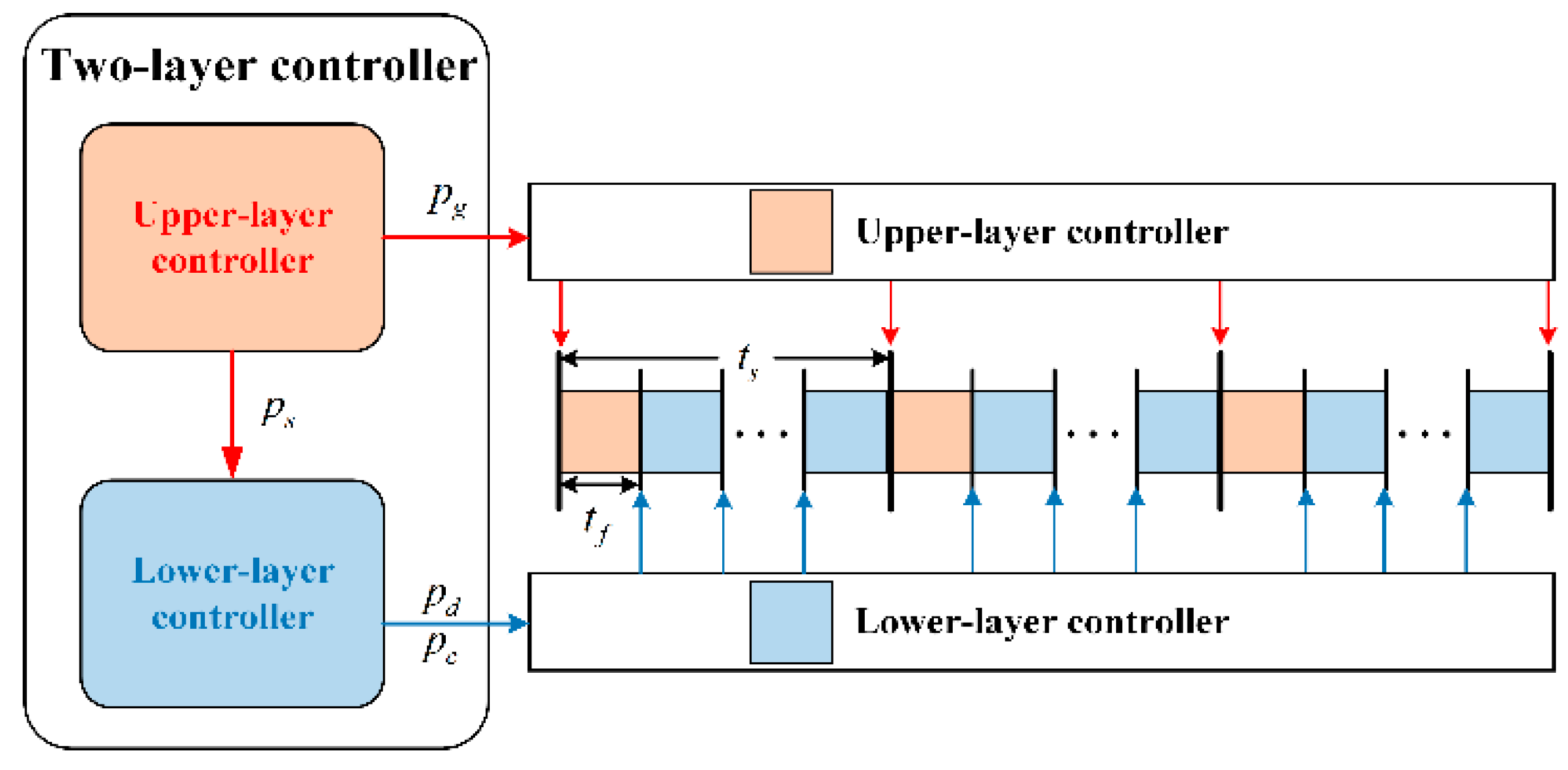
- A two-layer design decouples slow-timescale optimization (upper layer MPC-based control) from fast-timescale distributed execution (lower-layer broadcast-based control), significantly reducing the computational complexity.
- A broadcast-based control law ensures provable alignment between local DESS self-optimization and global voltage objectives, eliminating incentives for cost function manipulation.
- The lower-layer controller eliminates peer-to-peer communication dependencies, enhancing resilience against cyber threats and packet losses.
- The IEEE 34-bus and 123-bus test feeders are utilized to validate the efficacy of the proposed two-layer voltage control framework.
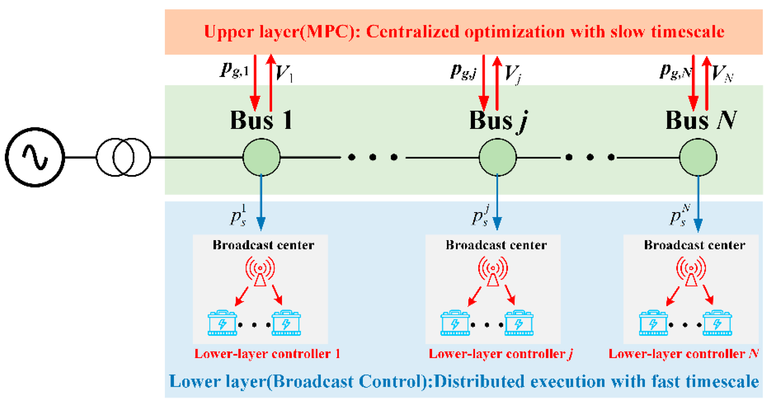
2. System Description
3. Proposed Control Strategy
3.1. Upper Layer Controller
3.2. Lower-Layer Controller
- (1)
- The computation complexity can be dramatic with the growing connection with DESSs;
- (2)
- The missing data caused by communication interruption may lead to a significant degradation in the control performance of (14)–(19).
- (1)
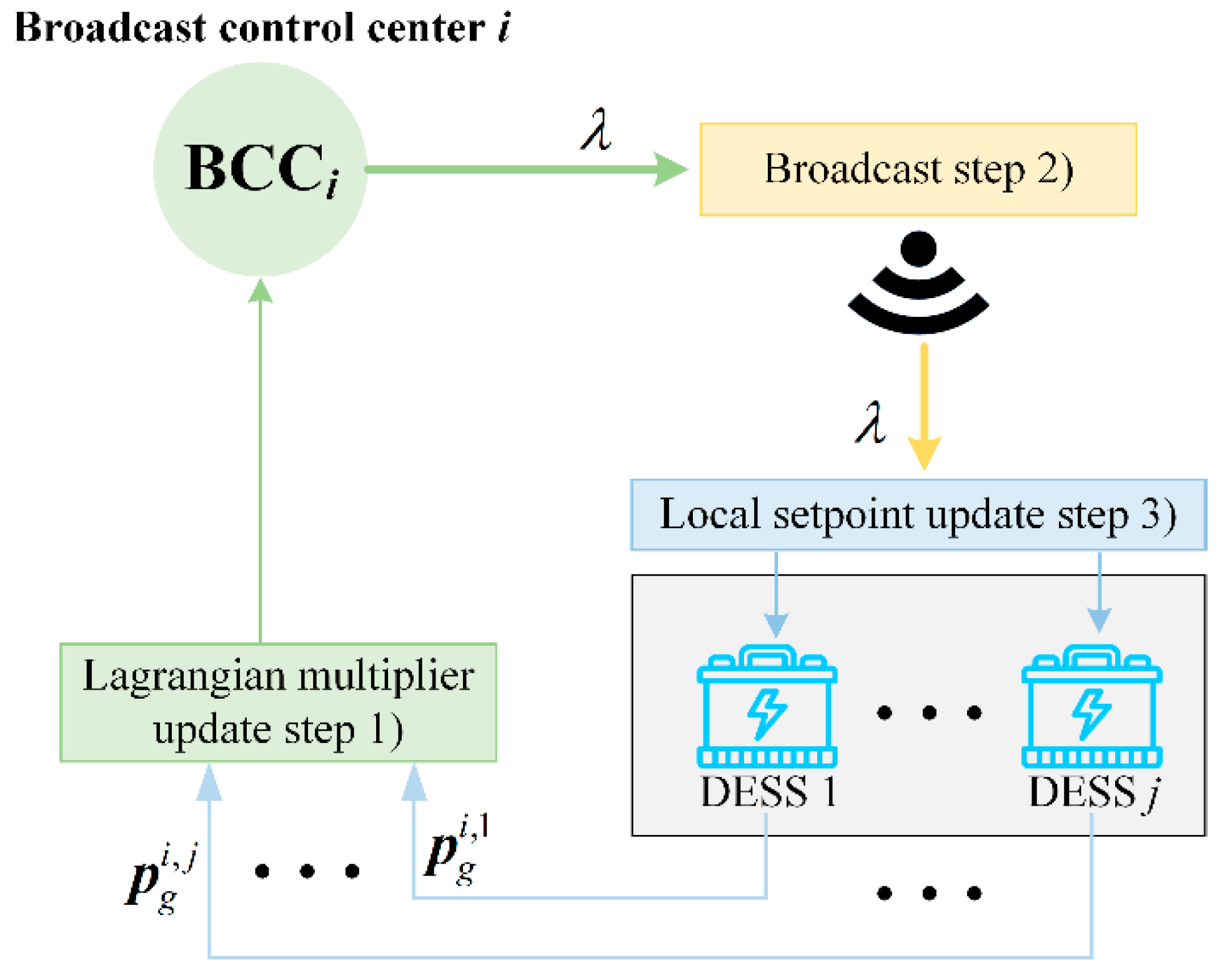
- The BBC collects the difference between the aggregated active power and the demand (i.e., ) for the real-time updating of the Lagrangian multiplier :where is a small positive constant.
- (2)
- The updated Lagrangian multiplier is sent to each DESSs.
- (3)
- After receiving the updated Lagrangian multiplier in (8), the active power point of each DESS j () is updated by:
3.3. Implementing of the Proposed Approach
- (1)
- Data Collection: Obtain the real-time measurement of voltage magnitudes and active power injections.
- (2)
- MPC Optimization: At the beginning of each , solve the optimization problem (8)–(13) to obtain the aggregated active power reference trajectories for critical buses.
- (3)
- Broadcast Execution: For the rest time of each , each bus employs the BBC to achieve autonomous active power tracking by DESS units.
- (4)
- Simulation Cycle: Repeat steps (1)–(3) until the end of the simulation.
4. Case Study
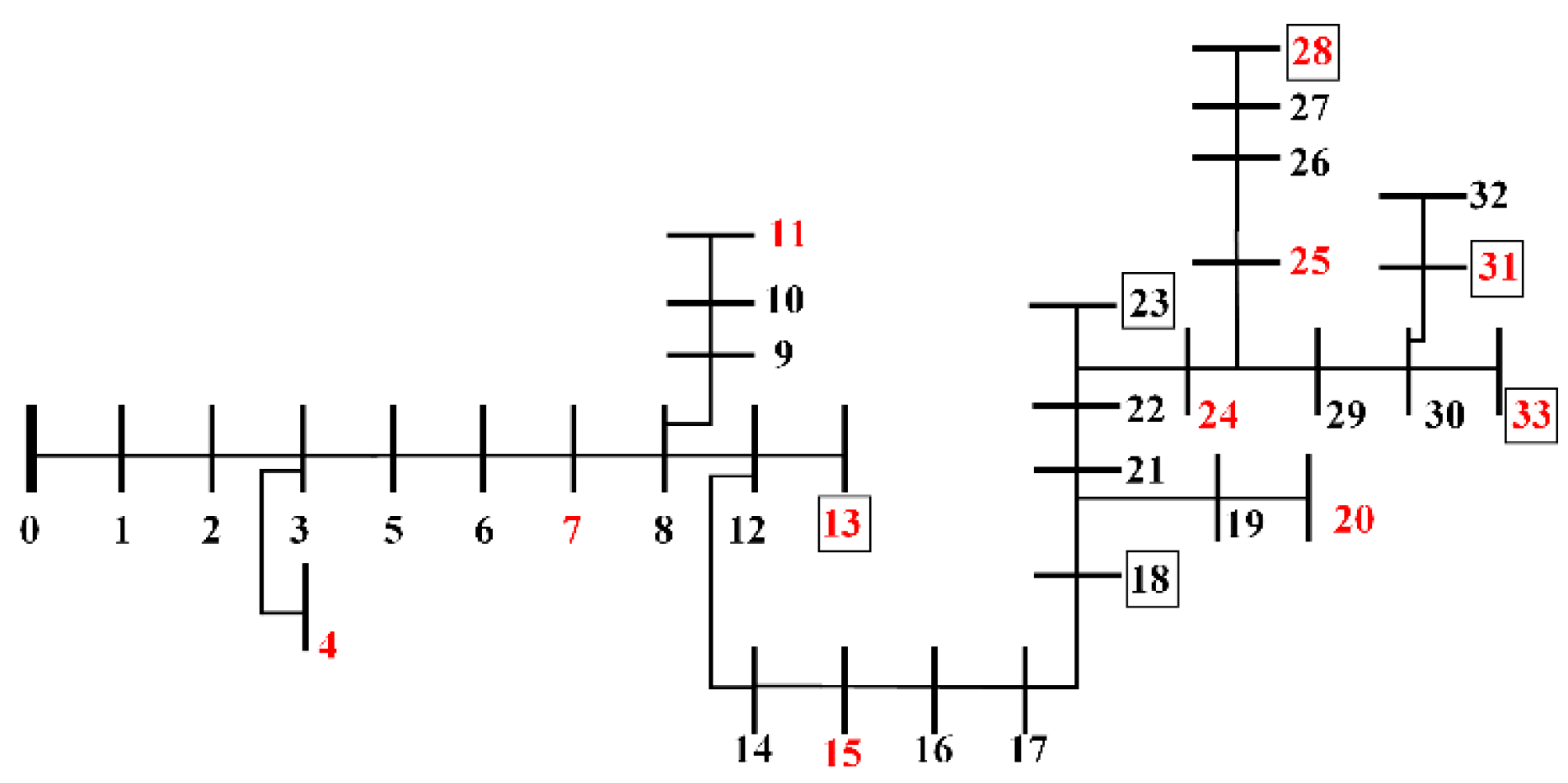
4.1. IEEE 34-Bus Test Feeder
4.2. IEEE 123-Bus Test Feeder
5. Conclusions
Author Contributions
Funding
Data Availability Statement
Acknowledgments
Conflicts of Interest
References
- Sun, H.; Guo, Q.; Qi, J.; Ajjarapu, V.; Bravo, R.; Chow, J.; Li, Z.; Moghe, R.; Nasr-Azadani, E.; Tamrakar, U.; et al. Review of challenges and research opportunities for voltage control in smart grids. IEEE Trans. Power Syst. 2019, 34, 2790–2801. [Google Scholar] [CrossRef]
- Murray, W.; Adonis, M.; Raji, A. Voltage control in future electrical distribution networks. Renew. Sustain. Energy Rev. 2021, 146, 111100. [Google Scholar] [CrossRef]
- Heydt, G.T. Electric power quality. In The Electrical Engineering Handbook; Elsevier Inc.: Amsterdam, The Netherlands, 2005; pp. 805–810. [Google Scholar]
- Xiong, W.; Tang, Z.; Cui, X. Distributed data-driven voltage control for active distribution networks with changing grid topologies. Control Eng. Pract. 2024, 147, 105933. [Google Scholar] [CrossRef]
- Zhang, K.; Chen, J.; Qi, X.; Zhang, W.; Wei, M.; Lin, D. Cooperative optimal operation of multi-microgrids and shared energy storage for voltage regulation of distribution networks based on improved Nash bargaining. Int. J. Electr. Power Energy Syst. 2025, 166, 110532. [Google Scholar] [CrossRef]
- Lou, G.; Gu, W.; Xu, Y.; Cheng, M.; Liu, W. Distributed MPC-based secondary voltage control scheme for autonomous droop-controlled microgrids. IEEE Trans. Sustain. Energy 2016, 8, 792–804. [Google Scholar] [CrossRef]
- Li, P.; Ji, J.; Ji, H.; Jian, J.; Ding, F.; Wu, J.; Wang, C. MPC-based local voltage control strategy of DGs in active distribution networks. IEEE Trans. Sustain. Energy 2020, 11, 2911–2921. [Google Scholar] [CrossRef]
- Wang, L.; Dubey, A.; Gebremedhin, A.H.; Srivastava, A.K.; Schulz, N. MPC-based decentralized voltage control in power distribution systems with EV and PV coordination. IEEE Trans. Smart Grid 2022, 13, 2908–2919. [Google Scholar] [CrossRef]
- Zarco-Soto, F.J.; Zarco-Periñán, P.J.; Martínez-Ramos, J.L. Centralized control of distribution networks with high penetration of renewable energies. Energies 2021, 14, 4283. [Google Scholar] [CrossRef]
- Guo, Y.; Wu, Q.; Gao, H.; Huang, S.; Zhou, B.; Li, C. Double-time-scale coordinated voltage control in active distribution networks based on MPC. IEEE Trans. Sustain. Energy 2019, 11, 294–303. [Google Scholar] [CrossRef]
- Zafar, R.; Ravishankar, J.; Fletcher, J.E.; Pota, H.R. Multi-timescale model predictive control of battery energy storage system using conic relaxation in smart distribution grids. IEEE Trans. Power Syst. 2018, 33, 7152–7161. [Google Scholar] [CrossRef]
- Azzouz, M.A.; Farag, H.E.; El-Saadany, E.F. Real-time fuzzy voltage regulation for distribution networks incorporating high penetration of renewable sources. IEEE Syst. J. 2014, 11, 1702–1711. [Google Scholar] [CrossRef]
- Tang, Z.; Hill, D.J.; Liu, T. Distributed coordinated reactive power control for voltage regulation in distribution networks. IEEE Trans. Smart Grid 2020, 12, 312–323. [Google Scholar] [CrossRef]
- Antoniadou-Plytaria, K.E.; Kouveliotis-Lysikatos, I.N.; Georgilakis, P.S.; Hatziargyriou, N.D. Distributed and decentralized voltage control of smart distribution networks: Models, methods, and future research. IEEE Trans. Smart Grid 2017, 8, 2999–3008. [Google Scholar] [CrossRef]
- Hu, J.; Ye, C.; Ding, Y.; Tang, J.; Liu, S. A distributed MPC to exploit reactive power V2G for real-time voltage regulation in distribution networks. IEEE Trans. Smart Grid 2021, 13, 576–588. [Google Scholar] [CrossRef]
- Song, G.; Wu, Q.; Jiao, W.; Lu, L. Distributed coordinated control for voltage regulation in active distribution networks based on robust model predictive control. Int. J. Electr. Power Energy Syst. 2025, 166, 110529. [Google Scholar] [CrossRef]
- Li, Z.; Wu, Q.; Chen, J.; Huang, S.; Shen, F. Double-time-scale distributed voltage control for unbalanced distribution networks based on MPC and ADMM. Int. J. Electr. Power Energy Syst. 2023, 145, 108665. [Google Scholar] [CrossRef]
- Wang, L.; Xie, L.; Yang, Y.; Zhang, Y.; Wang, K.; Cheng, S.-J. Distributed online voltage control with fast PV power fluctuations and imperfect communication. IEEE Trans. Smart Grid 2023, 14, 3681–3695. [Google Scholar] [CrossRef]
- Zhang, B.; Cao, D.; Hu, W.; Ghias, A.M.; Chen, Z. Physics-Informed Multi-Agent deep reinforcement learning enabled distributed voltage control for active distribution network using PV inverters. Int. J. Electr. Power Energy Syst. 2024, 155, 109641. [Google Scholar] [CrossRef]
- Huang, J.; Zhang, H.; Tian, D.; Zhang, Z.; Yu, C.; Hancke, G.P. Multi-agent deep reinforcement learning with enhanced collaboration for distribution network voltage control. Eng. Appl. Artif. Intell. 2024, 134, 108677. [Google Scholar] [CrossRef]
- Colot, A.; Stegen, T.; Cornélusse, B. Fully distributed real-time voltage control in active distribution networks with large penetration of solar inverters. In Proceedings of the 2023 IEEE Belgrade PowerTech, Belgrade, Serbia, 25–29 June 2023; pp. 1–6. [Google Scholar]
- Xu, J.; Mu, Y.; Cheng, W.; Gong, G.; Huang, J.; Zhang, T.; Hu, Q.; Chen, K.; Wu, A.Y. A Distributed Robust Voltage Control Framework for Active Distribution Systems. IEEE Trans. Ind. Appl. 2025, 61, 1896–1906. [Google Scholar] [CrossRef]
- Alrashidi, M.; Rahman, S. A bi-level optimization method for voltage control in distribution networks using batteries and smart inverters with high wind and photovoltaic penetrations. Int. J. Electr. Power Energy Syst. 2023, 151, 109217. [Google Scholar] [CrossRef]
- Rezaei, F.; Esmaeili, S. A bi-level inter-phase coordinated control method for voltage regulation in unbalanced LV distribution networks using PV-battery energy storage systems. J. Energy Storage 2024, 101, 113943. [Google Scholar] [CrossRef]
- Zhang, X.; Wu, Z.; Sun, Q.; Gu, W.; Zheng, S.; Zhao, J. Application and progress of artificial intelligence technology in the field of distribution network voltage Control: A review. Renew. Sustain. Energy Rev. 2024, 192, 114282. [Google Scholar] [CrossRef]
- Dörfler, F.; Grammatico, S. Gather-and-broadcast frequency control in power systems. Automatica 2017, 79, 296–305. [Google Scholar] [CrossRef]
- Baran, M.; Wu, F.F. Optimal sizing of capacitors placed on a radial distribution system. IEEE Trans. Power Deliv. 1989, 4, 735–743. [Google Scholar] [CrossRef]
- Zhu, H.; Liu, H.J. Fast local voltage control under limited reactive power: Optimality and stability analysis. IEEE Trans. Power Syst. 2015, 31, 3794–3803. [Google Scholar] [CrossRef]
- GUROBI. Available online: http://www.gurobi.com (accessed on 10 October 2018).
- IEEE PES Distribution Test Feeder 2017. Available online: https://cmte.ieee.org/pes-testfeeders/resources/ (accessed on 1 June 2017).
- Gong, J.; Lao, K.W. Electric spring for two-timescale coordination control of voltage and reactive power in active distribution networks. IEEE Trans. Power Deliv. 2024, 39, 1864–1876. [Google Scholar] [CrossRef]


| Parameters | Value |
|---|---|
| −8 kW | |
| 8 kW | |
| 25 kW·h | |
| 15 kW·h | |
| 80% | |
| 20% | |
| 96% |
| AVV | Maximum Voltage Magnitude (p.u.) | Minimum Voltage Magnitude (p.u.) | Cases |
|---|---|---|---|
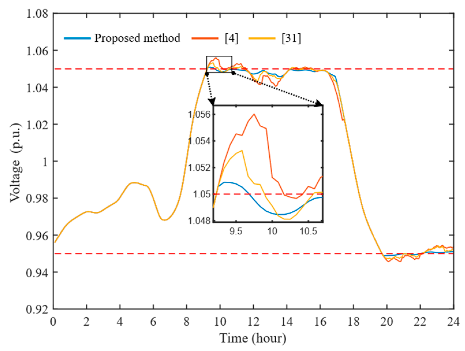
| 1.0509 | 0.9488 | With the proposed method | |
| 1.0560 | 0.9456 | With the method in [4] | |
| 1.0533 | 0.9470 | With the method in [31] | |
| 1.0651 | 0.9321 | Without control |
| Device Type | Installed Bus Numbers |
|---|---|
| PVs | 1, 20, 28, 32, 34, 39, 45, 50, 55, 57, 61, 69, 74, 81, 86, 92, 100, 107, 114, 117, 120, 122 |
| DESSs | 20, 28, 31,39, 45, 52, 55, 57, 61, 69, 74, 77, 92, 107, 117, 122 |
Disclaimer/Publisher’s Note: The statements, opinions and data contained in all publications are solely those of the individual author(s) and contributor(s) and not of MDPI and/or the editor(s). MDPI and/or the editor(s) disclaim responsibility for any injury to people or property resulting from any ideas, methods, instructions or products referred to in the content. |
© 2025 by the authors. Licensee MDPI, Basel, Switzerland. This article is an open access article distributed under the terms and conditions of the Creative Commons Attribution (CC BY) license (https://creativecommons.org/licenses/by/4.0/).
Share and Cite
Ma, C.; Xiong, W.; Tang, Z.; Li, Z.; Xiong, Y.; Wang, Q. A Hierarchical Voltage Control Strategy for Distribution Networks Using Distributed Energy Storage. Electronics 2025, 14, 1888. https://doi.org/10.3390/electronics14091888
Ma C, Xiong W, Tang Z, Li Z, Xiong Y, Wang Q. A Hierarchical Voltage Control Strategy for Distribution Networks Using Distributed Energy Storage. Electronics. 2025; 14(9):1888. https://doi.org/10.3390/electronics14091888
Chicago/Turabian StyleMa, Chao, Wenjie Xiong, Zhiyuan Tang, Ziwei Li, Yonghua Xiong, and Qibo Wang. 2025. "A Hierarchical Voltage Control Strategy for Distribution Networks Using Distributed Energy Storage" Electronics 14, no. 9: 1888. https://doi.org/10.3390/electronics14091888
APA StyleMa, C., Xiong, W., Tang, Z., Li, Z., Xiong, Y., & Wang, Q. (2025). A Hierarchical Voltage Control Strategy for Distribution Networks Using Distributed Energy Storage. Electronics, 14(9), 1888. https://doi.org/10.3390/electronics14091888