1. Introduction
Amid the relentless surge of digital transformation, sixth-generation mobile networks (6G) have emerged as the next frontier in communications, attracting global attention from both researchers and industries. 6G aims to achieve ultra-high data rates, ultra-low latency, and massive connection density to meet the stringent demands of future intelligent societies for massive data transmission and real-time interaction [
1]. Within the 6G technology framework, reconfigurable intelligent surface (RIS) technology has gained prominence as a key enabling technology. By intelligently manipulating the wireless propagation environment, an RIS can significantly enhance spectral efficiency, extend signal coverage, and improve link quality [
2]. Its unique working principles and advantages offer novel approaches to overcoming the limitations of conventional communication systems, potentially revolutionizing the communications paradigm in the 6G era. An RIS consists of a planar array comprising numerous low-cost, low-power passive reflecting elements. These elements can dynamically adjust the amplitude, phase, and even polarization state of incident electromagnetic waves, thereby altering signal propagation paths. Each unit can be independently controlled to reflect or refract incoming waves. Through programmable configurations, an RIS optimizes wireless links to enhance signal coverage, reduce communication power consumption, and improve spectral efficiency [
3,
4,
5,
6,
7].
As application scenarios grow increasingly diverse and complex, the limitations of conventional communication systems have become more pronounced. Terrestrial communication networks cannot provide a ubiquitous high data rate and reliable wireless connections, while UAV-assisted air-to-ground communication systems have gained widespread adoption due to their high mobility and ability to rapidly respond in complex geographical environments and harsh weather conditions [
8]. UAVs can be regarded as aerial relays or a base station (BS), whose lightweight and flexible nature enables rapid deployment in communication-challenged environments such as disaster zones, complex mountainous areas, and large-scale events or conferences. By adjusting flight trajectories and deployment positions, UAVs can efficiently accomplish communication tasks while establishing line-of-sight (LOS) links with ground users, effectively expanding communication coverage and enhancing data transmission rates [
9]. In recent years, numerous researchers have investigated communication systems combining UAVs with an RIS. Reference [
10] proposed an air-to-ground downlink communication network composed of an RIS and UAVs. The integration of RIS technology with UAVs in air-to-ground communication networks provides novel insights and directions for future communication network architecture design. Reference [
11] established a comprehensive and in-depth theoretical framework for the performance analysis of RIS-assisted UAV communication systems. Through rigorous mathematical derivation and analysis, the study quantitatively characterized the relationships between various system parameters and performance metrics.
However, most existing research on air-to-ground communication systems assumes perfect transceivers without considering HIs. In practical scenarios, HIs are unavoidable and significantly degrade communication performance, potentially causing link failures and data errors [
12,
13]. These impairments particularly affect performance gains in large-scale MIMO/MISO systems. Several studies have analyzed HI effects on communication systems. Reference [
14] developed a comprehensive RIS-assisted MIMO system model incorporating transceiver HIs, RIS phase noise, and other practical factors. Reference [
15] established a complete system model considering HIs and analyzed their impacts. Performance evaluation under HIs has become a research hotspot, revealing that a traditional passive RIS achieves limited gains in HI-affected environments. Dual-channel communication suffers from a multiplicative fading effect [
16], where combined air-to-ground and ground-to-air path losses create compounded signal degradation. To address this, reference [
17] proposed an ARIS capable of actively amplifying reflected signals. While an ARIS introduces thermal noise by integrating amplifiers into reflecting elements, it effectively compensates for path loss and mitigates multiplicative fading. Extensive ARIS performance evaluations have been conducted. Reference [
18] established a theoretical framework comparing an ARIS and a passive RIS across key metrics, cost, and complexity. Reference [
19] first revealed the security–reliability trade-off in UAV-mounted ARIS networks. Reference [
20] showed that large-scale ARIS arrays suffer from substantial energy consumption due to inter-element interference. To improve energy efficiency, reference [
21] proposed irregular ARIS configurations that strategically distribute active elements to create additional spatial degrees of freedom while reducing power consumption.
The real-world environment is far more complex than simulated experiments. To cope with potential fading and noise in practical scenarios, this study considers an air-to-ground communication system mitigated by HIs, specifically a system where a UAV equipped with an RIS serves as a relay. To address the fading and energy consumption issues of the proposed system, ARISs with dynamic topology are introduced to replace a traditional passive RIS. In summary, this paper proposes an optimized dynamic topology communication system of a UAV-ARIS based on HIs. The system uses energy consumption and the AAR as key metrics, formulating an optimization problem that maximizes the AAR through the joint optimization of dynamic topology, passive beamforming, active beamforming, and UAV trajectory. To solve this highly non-convex problem, we apply fractional programming [
22] to transform the original problem via Lagrangian dualization and quadratic transformation into a series of convex subproblems. The solution involves alternating the optimization of four subproblems: dynamic topology optimization using hybrid genetic–tabu search, beamforming optimization via semidefinite relaxation and successive convex approximation, and UAV trajectory optimization through successive convex optimization techniques.
To address these challenges, this work proposes the following: (1) a realistic communication model incorporating transceiver HIs and amplification thermal noise as additive noise components in the user SINR calculation; (2) a UAV-ARIS relay system employing a hybrid genetic algorithm for ARIS topology optimization to mitigate inter-element interference, combined with fractional programming and quadratic transformation for alternating subproblem optimization to maximize the AAR; (3) comprehensive performance comparisons demonstrating through simulations that the proposed UAV-ARIS dynamic topology optimization achieves a significantly higher AAR than a conventional passive RIS and other benchmark schemes. The solution specifically addresses multiplicative fading in dual-channel scenarios while maintaining energy efficiency through dynamic active element configuration, with the experimental results showing 27–130% AAR improvement and 19–32% energy savings compared to existing approaches under equivalent HI conditions.
2. System Model and Problem Description
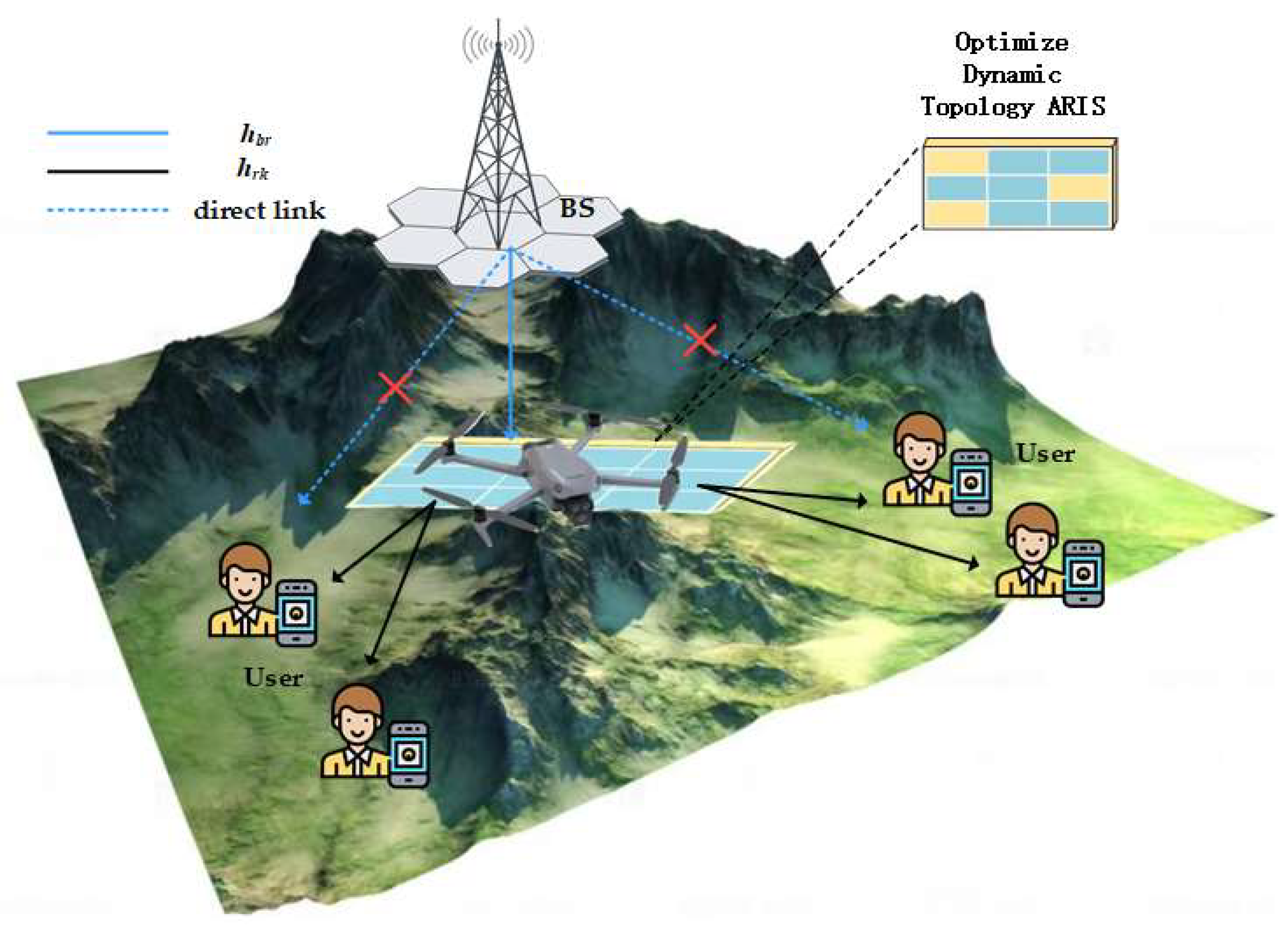
Consider an HI-aware UAV-ARIS communication system with optimized dynamic topology for downlink multiuser MISO transmission. As shown in
Figure 1, the system consists of a BS with
antennas transmitting signals via an ARIS containing
reflecting elements to
single-antenna users. Since the direct links between the BS and users are blocked in this system, they are not considered.
The user’s two-dimensional coordinates are denoted as
, with the UAV operating at a fixed altitude
with a flight period
discretized into
equal time slots
(i.e.,
), enabling its horizontal trajectory to be represented by
discrete points
in the 2D plane. The dynamic topology aerial ARIS, comprising
reflecting elements distributed across a rectangular array of
uniformly spaced grid points (
), features an inter-grid spacing of half the carrier wavelength. Given the LOS propagation characteristics of both the BS-to-UAV-ARIS and UAV-ARIS-to-ground-user links, the corresponding channel responses for the
n-th time slot are, respectively, modeled as
[
23].
where
is the array response in the
n-th time slot, let
denote the path loss exponent. In the
n-th time slot, the Euclidean distances between the BS and UAV, and between the UAV and the user, are denoted as
and
, respectively. The carrier wavelength and the spacing between reflecting elements on the RIS are represented by
and
, respectively. Furthermore,
and
correspond to the cosine of the angle of arrival (AoA) at the UAV from the BS and the cosine of the AoA at user
from the UAV in the
n-th time slot, respectively.
In this system, it is assumed that HIs are taken into account at both the transmitting and receiving ends. Then, the signal transmitted by the BS to the
k-th user in the
n-th time slot is
Let
denote the beamforming vector for user
k in the
n-th time slot, while
represents the information symbol transmitted from the BS to the
k-th user during the
n-th time slot. The HI distortion noise vector at the BS is denoted by
[
24]. It is modeled as uncorrelated Gaussian random variables, and
whose variance is proportional to the transmission power of the BS, where
characterizes the HI scaling factor at the BS. The received signal at the
k-th user in the
n-th time slot can then be expressed as
Let denote the dynamic topology matrix of the ARIS in the n-th time slot, where controls the on/off state of the m-th reconfigurable element in the n-th time slot, where “1” enables signal reflection and “0” disables reflection. The phase shift matrix for each time slot is given by , where represents the phase shift of the m-th reconfigurable element in the n-th time slot. is the amplitude coefficient, and .
Defining
, where
denotes expectation,
models the HI noise at the
k-th user, with corresponding HIs
denoting the HI scaling factor for the
k-th user equipment. Considering the ARIS incorporates active elements, its thermal noise
with amplified power
cannot be neglected, while
,
represents the additive white Gaussian noise at the BS. Consequently, the signal-to-interference-plus-noise ratio (SINR) for the
k-th user in the
n-th time slot is expressed as
where
, and
. The first term represents the interference between users, the second term represents the noise interference caused by HIs at the base station, the third term represents the thermal noise interference of the optimized dynamic topology ARIS, the fourth term represents the noise interference caused by HIs at the user end, and the fifth term represents the interference of additive white Gaussian noise. The achievable rate of the
k-th user in the
n-th time slot can be expressed as
A dynamic topology optimization framework is proposed for the UAV-ARIS in downlink cooperative systems with HIs. The focus is on jointly optimizing the ARIS dynamic topology matrix
, precoding matrix
W, phase shift matrix
, and UAV trajectory
to maximize the AAR. The problem is formulated as follows.
The proposed optimization framework sequentially adjusts four key parameters to maximize the AAR. The precoding matrix W is specifically defined as . The solution is subject to eight critical constraints: () the dynamic topology ARIS’s amplification power cannot exceed ; () the base station’s maximum transmit power is bounded by ; () the ARIS amplification gain must satisfy amplitude limitations; () the topology matrix requires unit diagonal elements to maintain specific reflection properties; () phase shifts in the ARIS must adhere to unit modulus constraints; () the UAV’s initial position is fixed at a predetermined location; and () the UAV’s mobility is constrained by maximum velocity limitations.
3. Algorithm Design
In the considered problem, the variable is highly coupled. Therefore, a method of using fractional programming to decouple the four variables is proposed. Firstly, the Algorithm 1 is employed to solve for . It is assumed that after obtaining the optimal , the topological structure remains fixed within the same time slot. However, the original problem is still non-convex and is a logarithmic polynomial. To address this issue, a quadratic transformation is proposed to convert the coupled non-convex multi-variables into a single convex variable. Finally, an approximate solution is obtained through Algorithm 2.
3.1. Solve Based on the HGA
To solve the topology matrix of the ARIS, an HGA is proposed to search for high-quality optimal solutions. The proposed algorithm combines the genetic algorithm and the TSA to balance the breadth and depth of the search.
Specifically, in the genetic algorithm, for the P chromosomes in the population, a corresponding relationship between chromosomes and the topology matrix is established, with each topology structure corresponding to one chromosome. The average achievable rate (AAR) of the system is defined as the fitness of the algorithm, meaning that the AAR is positively correlated with the fitness of the algorithm; the higher the fitness, the better the individual topology matrix . A crossover operator is applied to combine two parent individuals to generate new offspring individuals. To avoid premature convergence, the roulette wheel selection method is used to implement the mutation operation, where the selection probability of each individual is equal to its fitness value divided by the total fitness value of the population. Since the elements in matrix only contain 0 and 1, the mutation of gene values is set as changing 1 to 0 and 0 to 1.
The local optimal topology matrix obtained by the genetic algorithm is used as the initial solution for the TSA. Randomly select
p chromosomes with a value of 0 from the current solution and change them to 1, and randomly select
p chromosomes with a value of 1 and change them to 0 to obtain the “neighboring solutions”. Calculate the fitness of the neighboring solutions and compare them with the current solution. If the fitness of a neighboring solution is higher, select it as the new optimal solution. During the iteration process, a tabu list is used to store recently generated records to avoid periods and repetitions. Through the tabu list mechanism, the algorithm can escape from the local optimal solution and explore new solution spaces. The length of the tabu list is fixed at
. After the solution process, the optimized topology matrix
is obtained, and the original problem is rewritten as
where
. The specific algorithm details are shown in Algorithm 1.
| Algorithm 1 Hybrid Genetic–Tabu Search Algorithm |
| 1: Initialize the tabu list , the maximum value of the tabu list as , the crossover probability as , the mutation probability as , the distance to the neighboring neighbor , the topology matrix of the optimized dynamic topology ARIS, the iteration number I, and the maximum iteration number . |
| 2: Calculate the maximum value of the AAR of the population P in the system as the fitness. |
| 3: for . |
| 4: Genetic algorithm operations |
Select parents from the population P using a selection method based on fitness. Perform crossover operations on the selected parents with probability to generate offspring. Perform mutation operations on the offspring with probability .
|
| 5: TSA search operations |
|
Exclude the tabu neighbors from the tabu list to obtain the candidate neighbors . Calculate the AAR of all candidate neighbors and save the maximum value as the best candidate, denoted as .
|
if then Add to else Add to the end and delete the first element. end if
|
end for |
3.2. Fractional Programming
For a given topology matrix
, there are highly coupled non-convex variables and non-convex constraints in the objective function. Since the objective function is a logarithmic polynomial, fractional programming is used for transformation. Firstly, auxiliary variables are introduced for Lagrangian dualization, and Equation (7) is expressed as
where
are introduced as Lagrangian auxiliary variables. In order to maximize the objective function by iterative optimization for all variables, when fixing
, the auxiliary variables
can be determined via the optimal solution
.
Substitute it back into Equation (9), and after removing the constant terms, the problem can be equivalently transformed into solving
3.3. Active Beamforming
In order to optimize the transmit beam of the base station and simplify the formula, let
in Equation (11), and the original problem is reformulated as
A quadratic transformation of Equation (12) further transforms the problem into
where
is the quadratic transformation auxiliary variable. Let
,
, then the optimal solution can be obtained as
The optimal solution of
can be obtained by using the Lagrange multiplier method as follows
where
is the dual variable introduced for active beamforming.
3.4. Passive Beamforming
The passive beamforming of the system is equivalent to optimizing
. According to Equation (11), by fixing
, the original problem is reformulated as
where
,
,
,
. Perform a quadratic transformation on Equation (16), and it can be further expressed as
where
is the quadratic transform auxiliary variable. Let
,
. The Quadratically Constrained Quadratic Programming (QCQP) of Equation (17) is equivalent to
Further perform matrices transformation to simplify the expression.
The QCQP for passive beamforming is rewritten as
Equation (12) is a semidefinite programming problem, which can be solved by semidefinite relaxation, and an approximate solution that satisfies the rank-one constraint can be obtained through the method of Gaussian randomization.
3.5. Optimizing UAV Trajectories
In order to optimize the trajectory of the UAV, by fixing
, and following Equation (12), a quadratic transformation is performed on it, resulting in
Among them,
is the auxiliary variable for the quadratic transformation. The signals received by the user from the reflections of different cells are coherent. Therefore, in order to improve the quality of the received signals, coherent processing is carried out on the signals. Firstly, the signal at the receiving end is redefined as
where
represents the amplitude of the
m-th reflection unit, and
represents the phase of the m-th reflection unit. Perform a coherent combination on the signals and let
. Further, the entire signal is rewritten as
By introducing the slack variables
and
, the problem
can be formulated as
where
,
,
,
,
. When the slack variables remain equal,
and
have the same optimal solution. In order to address the non-convexity of the problem, a first-order Taylor expansion is carried out at the point
within the feasible region, and obtain
where
,
,
. Therefore,
can be approximated as
The problem
is a convex optimization problem and can be solved efficiently using CVX.
| Algorithm 2 Algorithm based on quadratic transform alternating optimization method |
| Initialization: |
| 1 Repeat . |
| 2 Based on the hybrid genetic algorithm, is solved, and the optimal topology matrix is obtained. |
| 3 According to the given , solve and obtain . |
| 4 According to the given , solve and obtain . |
| 5 According to the given , solve and obtain . |
| 6 Until: converge to the specified precision. |
3.6. Algorithm Complexity
For the non-convex problem with highly coupled multi-variables, the complexity of the proposed quadratic transformation is , where is the number of variables. The computational complexity of the genetic–tabu hybrid algorithm for optimizing the dynamic topology structure is , where is the number of iterations, is the individual coding length, and is the length of the tabu list. The computational complexity of the semidefinite relaxation algorithm is related to the number of iterations and the number of updated variables in each iteration, and its computational complexity is . The computational complexity of the successive convex approximation algorithm is related to the number of variables, and its computational complexity is . The complexity of the trajectory optimization algorithm is , where is the number of terms in the calculation. The overall algorithm is related to the experimental parameters and the number of iterations. Among them, the growth order of the semidefinite relaxation algorithm is the highest, and the overall algorithm complexity can be approximated as .
4. Simulation Analysis
In this section, the effectiveness of the UAV-ARIS optimized dynamic topology scheme-assisted communication scheme is verified through simulations. The key parameter settings are as follows:
Figure 2 shows the 3D coordinate system of the multiuser air-to-ground communication network assisted by the dynamic topology of the UAV-ARIS. The system parameters are as shown in the environmental parameters and system parameters in
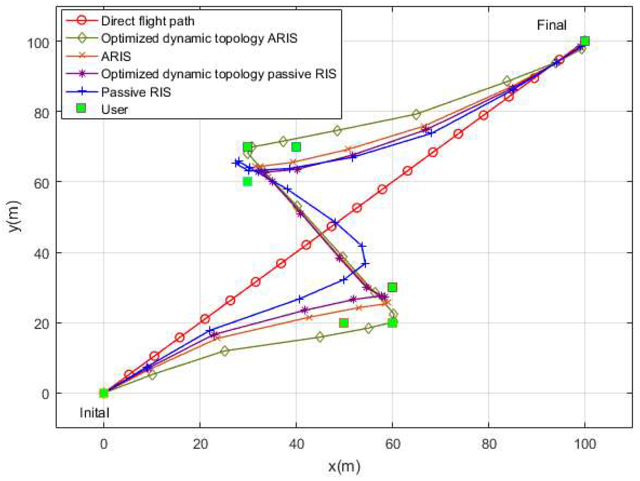
Table 1. In the simulation, the starting point (the location of the BS) and the ending point are set as (0 m, 0 m) and (100 m, 100 m), respectively. The coordinates of the six communication users are (50 m, 20 m), (60 m, 20 m), (60 m, 30 m), (30 m, 60 m), (30 m, 70 m), and (40 m, 70 m), respectively. To conduct a performance analysis of the proposed scheme, the following schemes are presented for comparison:
- (i)
The optimized dynamic topology ARIS scheme, namely, the UAV, is equipped with the optimized dynamic topology ARIS to serve as a relay for communication.
- (ii)
The ARIS scheme, that is, the UAV, is equipped with the conventional ARIS to serve as a relay for communication.
- (iii)
The optimized dynamic topology passive RIS scheme, that is, the UAV, is equipped with the optimized dynamic topology passive RIS to serve as a relay for communication.
- (iv)
The passive RIS scheme, namely, the UAV, is equipped with the conventional passive RIS to serve as a relay for communication.
- (v)
The random phase shift scheme, that is, the UAV, is equipped with the ARIS with random phase shift to serve as a relay for communication.
Figure 3 shows a comparison diagram between the direct flight path of the unoptimized UAV and the flight paths of various optimized schemes. Here, the users are scattered on both sides of the straight line connecting the starting and ending points. All the optimized schemes achieve user tracking, optimize the communication channels, and verify the effectiveness of the algorithm. The flight period of all schemes is
. Within the limited flight period, it is considered that the smaller the path loss, the better the channel gain provided. It can be seen that the optimized dynamic topology ARIS scheme gets closer to the users clustered on both sides. This is because the optimized dynamic topology ARIS has an active characteristic that can actively amplify and adjust signals, enabling the UAV to maintain good communication even when it is farther away from the base station. In other words, the optimized trajectory can extend to areas where communication was originally restricted. Even for the passive RIS schemes, the one with the optimized dynamic topology structure demonstrates a more efficient flight path.
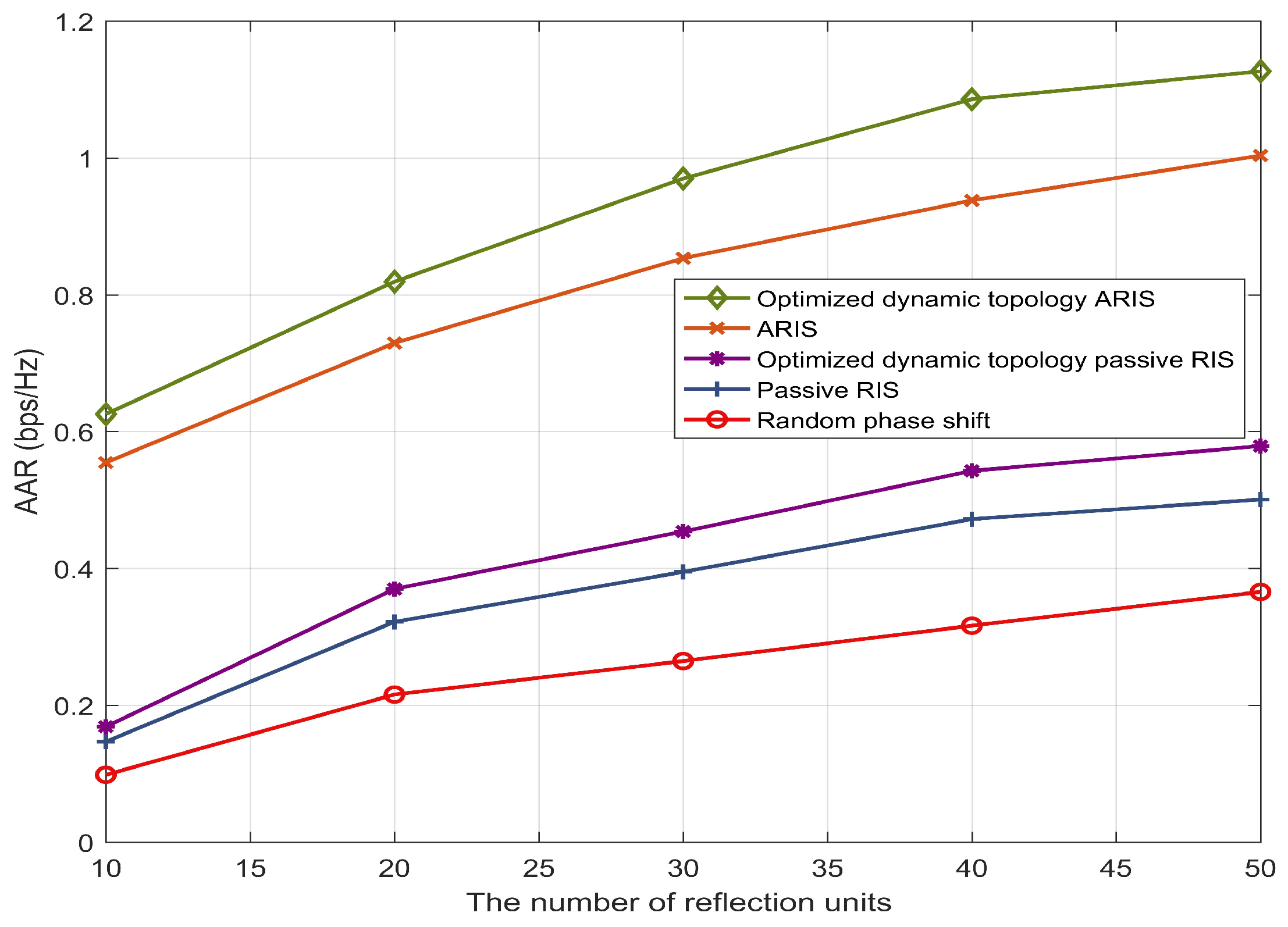
Figure 4 compares the changes in the AAR of different schemes as the number of RIS reflection units increases. The AAR of all schemes increases with the increase in the number of reflection units. Compared with the random phase shift scheme, all other schemes have achieved significant improvements. The gain of the proposed beamforming algorithm on the AAR demonstrates the excellent effect of the algorithm in optimizing communication performance. When the number of reflection units is 50, the AAR of the optimized dynamic topology ARIS scheme is 108% higher than that of the optimized dynamic topology passive RIS scheme. This is because the ARIS amplifies the reflected signal, compensating for the path damage caused by the “double fading” effect. The AAR of the optimized dynamic topology ARIS scheme is 21% higher than that of the ARIS scheme. This is because, with the same number of units, the optimized dynamic topology ARIS selects units with better channel gain conditions to enhance communication performance. This indicates that the proposed topology optimization strategy has achieved obvious results. The schemes with the UAV carrying the ARIS show a significant gap compared with other benchmark schemes, which is mainly the result of the signal amplification brought about by the ARIS. The traditional passive RIS schemes also show a distinct difference depending on whether the topology optimization and the beamforming algorithm optimization are carried out, further verifying the superiority and effectiveness of the proposed scheme.
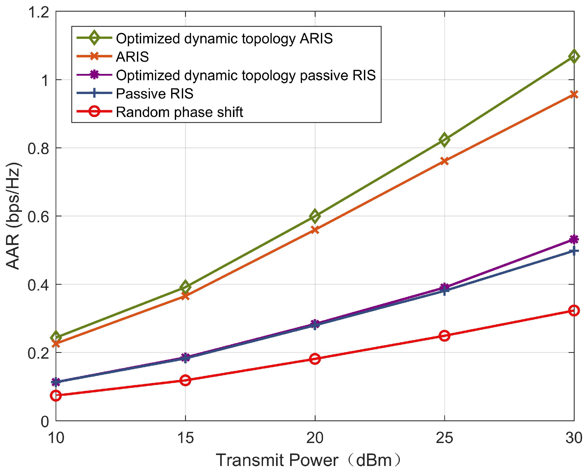
Figure 5 depicts how the AAR of different schemes varies with the transmit power of the base station. The AAR of all schemes increases as the transmit power of the base station increases, and the optimized dynamic topology ARIS scheme is significantly higher than the other schemes. When compared with the optimized dynamic topology ARIS and the optimized dynamic topology passive RIS, at a base station transmit power of 30 dBm, the optimized dynamic topology ARIS shows an improvement of 109%, while at a transmit power of 15 dBm, the improvement is 33%. This is because at low power levels, the influence of the noise floor limits its gain, and it cannot achieve a high gain as it does at high power levels. The nonlinear characteristic exhibited between power and gain reflects that in high-power application scenarios, the advantages of the optimized dynamic topology ARIS are more pronounced. However, even when the transmit power is 15 dBm, the AAR of the optimized dynamic topology ARIS is still 130% higher than that of the optimized dynamic topology passive RIS scheme. This indicates that under the same power constraints, the signal improvement effect of the ARIS is far higher than that of the passive RIS.
Figure 6 illustrates how the energy efficiency of different schemes changes as the transmit power increases. With the increase in the transmit power of the base station, the energy efficiency of all the scheme systems first gradually increases and then tends to stabilize. The reason is that as the transmit power increases, more power is allocated to the users, and the energy efficiency of the system becomes higher. At the same time, the system noise is also increasing. That is to say, after reaching the optimal transmit power value, the energy efficiency of the system stabilizes. Among the stabilized energy efficiency values, the optimized dynamic topology ARIS has a 19% improvement compared with the RIS, and the optimized dynamic topology passive RIS has a 32% improvement compared with the passive RIS. In the schemes with the ARIS, the significant improvement in energy efficiency effectively saves the overall system energy consumption. The reason is that the optimized dynamic topology matrix of the optimized dynamic topology ARIS optimizes the matrix energy consumption cost, saving costs while greatly improving energy efficiency. The passive devices in the passive RIS scheme do not involve unit energy consumption, but as a result, the signal gain is also sacrificed.
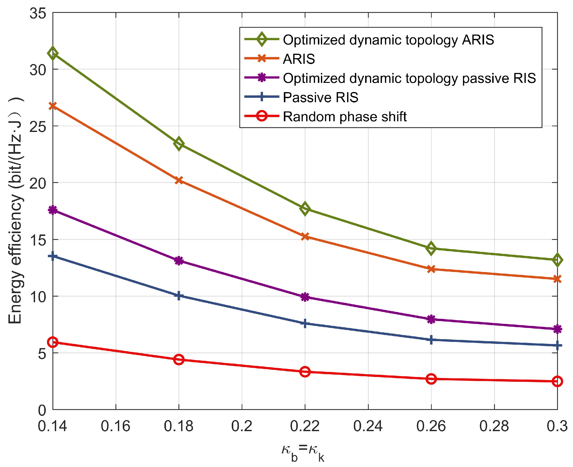
Figure 7 describes the relationship between the energy efficiency and the HI factor. As is clearly visible in
Figure 4, as the HI factor increases from 0.14 to 0.3, the energy efficiency of the system decreases significantly. The increase in the hardware impairment factor leads to an increase in system noise, and the overall performance decreases accordingly. When the HI factor rises from 0.14 to 0.3, the optimized dynamic topology ARIS scheme decreases by 59%, the RIS scheme decreases by 53%, the optimized dynamic topology passive RIS scheme decreases by 60%, the passive RIS scheme decreases by 57%, and the random phase shift scheme decreases by 56%. This demonstrates the necessity of considering hardware impairments. In real-world scenarios, the service life, device environment, and power level all affect the working efficiency of the transmitting and receiving hardware. Therefore, it is extremely necessary to evaluate the communication system based on hardware impairments.
Figure 8 describes the relationship between the AAR in the optimized dynamic topology ARIS scheme and the change in the flight period. It can be seen that the longer the flight period is, the higher the user AAR is. This is because as the number of flight time slots increases, the UAV hovers above the users for more time slots, and the signal gain provided is larger. In addition, when
is reached, the optimized dynamic topology ARIS scheme reaches the optimal hovering period of the established route, and increasing the flight period does not bring obvious gain to the AAR. For other schemes, the AAR continues to increase after the flight period is increased, which is consistent with the flight trajectory shown in
Figure 3. This is because more flight periods provide more time slots to improve the user channels, and there is enough room to optimize the reflection channels. However, in practical situations, the power loss caused by a longer flight period will be huge, and the flight cost of the UAV cannot be ignored.
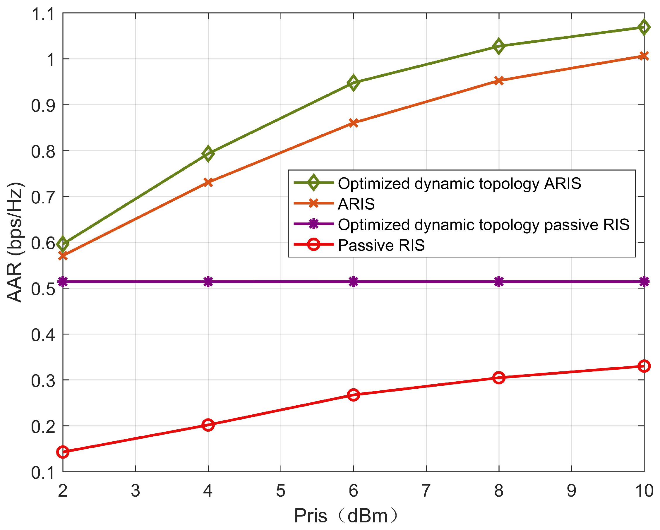
Figure 9 describes the changes in the AAR of the active scheme, the passive scheme, and the random phase shift scheme as the transmit power of the RIS increases. It can be seen that, except for the passive scheme, all the schemes equipped with the ARIS increase as the transmit power of the RIS increases. Due to the power limitation, the growth rate gradually decreases. However, even when
occurs, the passive RIS scheme is still far greater than the random phase shift scheme. This demonstrates the effectiveness of the proposed algorithm. The beamforming of the random phase shift has significantly improved the user’s AAR. Moreover, at this time, compared with the ARIS and passive schemes, the AAR of users in the optimized dynamic topology ARIS scheme has increased by 20% and 136%, respectively, further verifying the effectiveness of the proposed relay system in terms of communication gain.
Figure 10 describes the convergence of the algorithms of the five schemes, with the convergence accuracy set to
. After the objective function is subjected to fractional programming and Lagrangian dualization, and then through quadratic transformation, decoupling, and alternating iterative optimization, the entire algorithm converges within five iterations. Among them, due to the amplification characteristics, the growth range of the AAR of users before convergence in the optimized dynamic topology ARIS scheme and the ARIS scheme equipped with the ARIS is much larger than that of other schemes. The stable convergence of all schemes verifies the rationality of the algorithm.
In summary, when the number of reflective units is 50 and the base station transmit power is 30 dBm,
Table 2 presents a comparison of the AAR and energy efficiency under different schemes. Compared with the ARIS scheme, the optimized dynamic topology ARIS scheme increases the AAR by 21% and improves the energy efficiency by 19%. Therefore, it can be concluded that the proposed joint optimization scheme of the UAV-mounted ARIS with dynamic topology provides better performance and higher energy utilization.


