Article

Pose Measurement of Non-Cooperative Space Targets Based on Point Line Feature Fusion in Low-Light Environments

1
School of Optoelectronic Engineering, Xidian University, Xi’an 710071, China
2
Xi’an Institute of Optics and Precision Mechanics of CAS, Xi’an 710119, China
3
Xi’an Key Laboratory of Spacecraft Optical Imaging and Measurement Technology, Xi’an 710119, China
*
Author to whom correspondence should be addressed.
Electronics 2025, 14(9), 1795; https://doi.org/10.3390/electronics14091795
Submission received: 17 March 2025 / Revised: 24 April 2025 / Accepted: 25 April 2025 / Published: 28 April 2025

Abstract

:
Pose measurement of non-cooperative targets in space is one of the key technologies in space missions. However, most existing methods simulate well-lit environments and do not consider the degradation of algorithms in low-light conditions. Additionally, due to the limited computing capabilities of space platforms, there is a higher demand for real-time processing of algorithms. This paper proposes a real-time pose measurement method based on binocular vision that is suitable for low-light environments. Firstly, the traditional point feature extraction algorithm is adaptively improved based on lighting conditions, greatly reducing the impact of lighting on the effectiveness of feature point extraction. By combining point feature matching with epipolar constraints, the matching range of feature points is narrowed down to the epipolar line, significantly improving the matching speed and accuracy. Secondly, utilizing the structural information of the spacecraft, line features are introduced and processed in parallel with point features, greatly enhancing the accuracy of pose measurement results. Finally, an adaptive weighted multi-feature pose fusion method based on lighting conditions is introduced to obtain the optimal pose estimation results. Simulation and physical experiment results demonstrate that this method can obtain high-precision target pose information in a real-time and stable manner, both in well-lit and low-light environments.

1. Introduction

Relative pose measurement of space targets is one of the key technologies in spacecraft missions. It is required to accurately and in real time obtain the spatial relative pose between target spacecraft and servicing spacecraft in tasks such as space debris removal, spacecraft rendezvous and docking, on-orbit maintenance, and assembly [1,2,3,4,5,6,7].
Currently, many flight missions involving multiple space targets in space often involve interactions between non-cooperative spacecraft. Due to the absence of reference markers and prior information on motion or structure for non-cooperative spacecraft, the problem of estimating relative pose states becomes even more complex. Additionally, due to the limited computing capability of space platforms, an accurate and real-time solution for measuring the pose of space targets is an urgent problem that needs to be addressed in space missions.
With the development of deep learning, using deep learning to achieve non-cooperative target pose estimation is a promising research area that can greatly improve measurement results [8,9,10]. However, deep learning algorithms require a large amount of data, most of which come from simulations of real-world spaces. Additionally, the accuracy of pose estimation relies entirely on the information in the dataset itself. When there is a significant difference between the new pose estimation model and the dataset, the accuracy can decrease sharply. Furthermore, due to the limitations of computational power in space platforms, it is challenging to deploy deep learning algorithms and achieve real-time measurements.
Traditional methods for pose estimation based on optical stereo cameras can meet the requirements of real-time measurement for spacecraft. Non-cooperative target pose estimation based on stereo cameras is currently an active area of research [1,11,12,13]. The advantage of using a measurement system composed of stereo cameras is that it can obtain depth information and three-dimensional information of the target without the need for additional light sources by utilizing the principles of geometric views. This system effectively compensates for the limitations of depth information in single monocular cameras [6,14]. Compared to various active measurement methods such as TOF cameras [15] and LiDAR [16,17], the system using stereo cameras has the advantages of compact size, passive operation, simple hardware, and low power consumption, making it highly suitable for pose estimation in space.
Existing solutions can be roughly divided into three categories. The first category is geometry-based methods: integrating object detection algorithms or feature point detection algorithms into traditional geometric feature priors to achieve high-precision acquisition. For example, Liu [18] proposed a stereo vision solution based on object detection and adaptive circle extraction, which effectively alleviates the challenges of pose measurement under ultra-close-range weak illumination conditions. Shan [15] designed a planar target centered on annular structures specifically for object pose measurement. For this target, a feature point coordinate extraction and sorting algorithm was developed to efficiently extract image features. Wang [19] proposed a method to identify natural features of non-cooperative spacecraft and measure their poses based on rectangular shapes. Although these methods achieve high accuracy in controlled environments, they impose stringent requirements on the special structural features of detection targets, making them difficult to detect and resulting in limited generalization capability on unstructured space targets. The second category is learning-based frameworks: typical examples include Yuan [20], who introduced a non-coplanar keypoint selection network with uncertainty prediction, pioneering the ability to accurately estimate the pose of non-cooperative spacecraft. Then, based on the camera model, the 3D positions of feature points are calculated to estimate their relationships. Gao [21] proposed a deep learning-based online 3D modeling method using stereo cameras for pose estimation under uncertain dynamic occlusion, though its stability still requires further verification. Despite their innovativeness, such methods exhibit insufficient detection robustness under extreme spacecraft illumination conditions, high computational overhead, and limited interpretability. The third category is sensor fusion: hybrid solutions combining LiDAR and vision can mitigate illumination-related challenges but introduce prohibitive computational costs for real-time spacecraft operations.
In most space missions, target spacecraft lack artificial markers and cannot provide cooperative information to service spacecraft. Additionally, since spacecraft surfaces are covered with reflective materials, feature detection and matching are highly susceptible to intense illumination variations in space. However, their rectangular solar panels—fundamental components with large surface areas and rich features—are readily detectable. Leveraging the structural characteristics of solar panels, we improved traditional point feature extraction algorithms by introducing an illumination-based adaptive threshold. Simultaneously, we integrated epipolar constraints with point feature matching to narrow the matching search space from 2D to the epipolar line, significantly enhancing both matching speed and accuracy. To further optimize performance, we exploited the parallel computing capabilities of hardware to implement parallel line feature extraction and matching, enabling concurrent processing of point and line features. This approach ensures high efficiency and precision in feature matching. Finally, to address the unique challenges of the space environment, we developed an adaptive weighted multi-feature pose fusion algorithm. This method fully utilizes fused point-line features and iteratively refines pose estimation results for higher accuracy.
In summary, we propose a real-time pose measurement method based on binocular vision for non-cooperative target pose estimation in low-light environments in space. Our work has three advantages over other methods:
(1)
Improved traditional point feature algorithms to reduce the impact of illumination on feature extraction performance. By combining point feature matching with epipolar constraint, we narrow the matching range of points from two dimensions to the epipolar line, greatly improving matching speed and accuracy.
(2)
Introduced line features based on the structural information of the spacecraft. These features are extracted and matched in parallel with point features to achieve preliminary pose measurement, greatly ensuring the precision and accuracy of the pose measurement results.
(3)
Introduced an adaptive weighted multi-feature pose fusion based on illumination, fully integrating point-line matching features to obtain the optimal pose estimation result.

2. Related Work

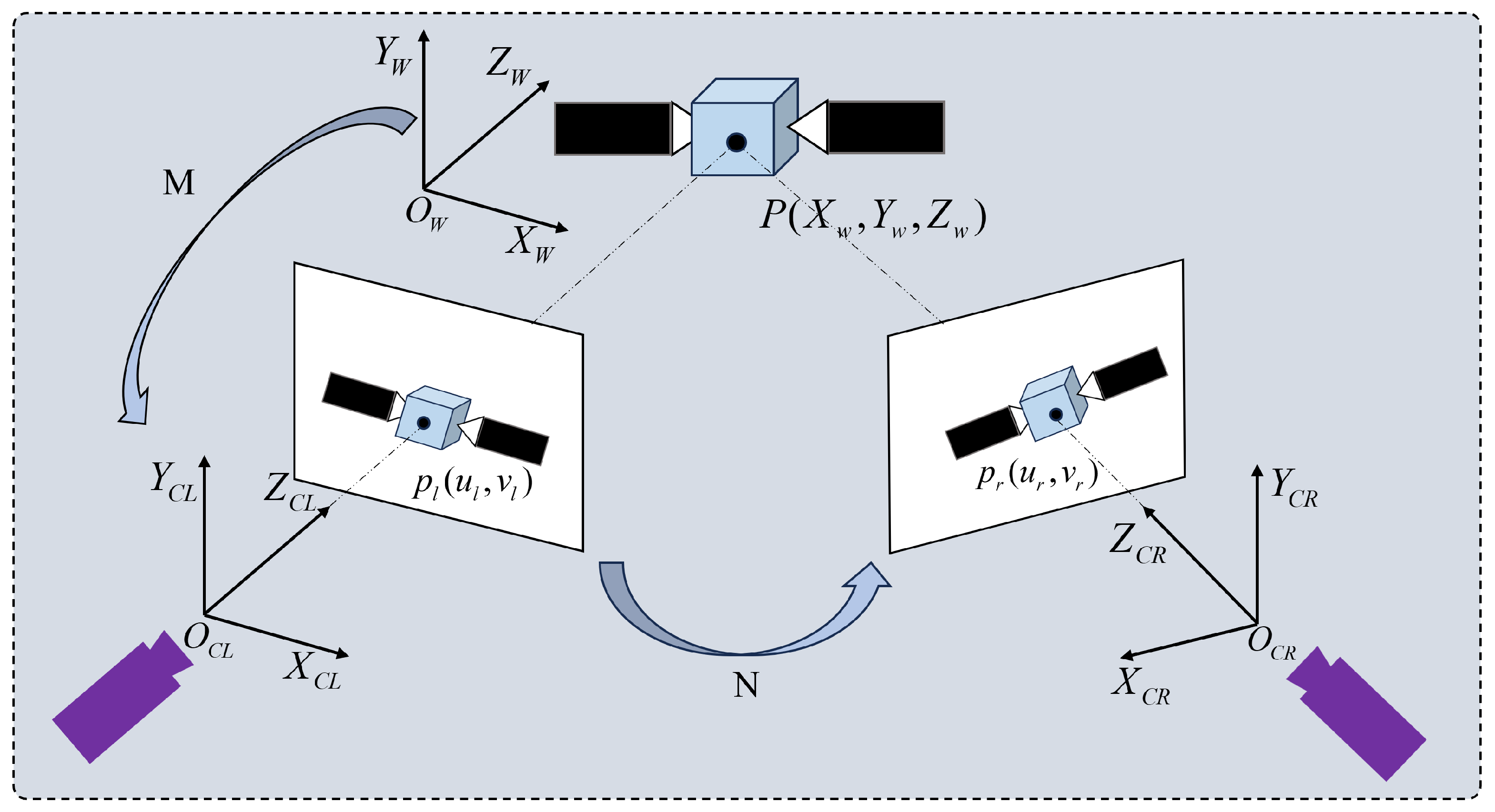
2.1. Binocular Vision System

The non-cooperative spacecraft pose estimation system based on stereo cameras has always been an important research field. Figure 1 represents a schematic diagram of the binocular pose measurement model, where the left camera coordinate system is denoted as  O C L X C L Y C L Z C L . The coordinate system of the right camera is denoted as  O C R X C R Y C R Z C R , and the origin of the left camera coordinate system is located at the optical center of the left camera, denoted as  O C L . The  X C L  axis is parallel to the rows of the image, the  Y C L  axis is parallel to the columns, and the  Z C L  axis is the optical axis of the left camera. Similarly, in the right coordinate system, the  O C R  origin is located at the optical center of the right camera, the  X C R  axis and the  Y C R  axis are parallel to the rows and columns of the right image, and the  Z C R  axis is the optical axis of the right camera. The world coordinate system coincides with the left camera coordinate system. For any arbitrary point P on the surface of the satellite, its world coordinate system coordinates are  ( X w , Y w , Z w ) , the projection point in the left camera is  P l  with pixel coordinates  ( u l , v l ) , and the projection point in the right camera is  P r  with pixel coordinates  ( u r , v r ) . The world coordinate system can be transformed to the pixel coordinate system using the spatial transformation matrix M, and the transformation relationship is given by Equation (1).
u v 1 = r 1 r 2 r 3 t x r 4 r 5 r 6 t y r 7 r 8 r 9 t z X w Y w Z w 1 = M X w Y w Z w 1
M is the transformation matrix in the spatial domain,  ( X w , Y w , Z w )  represents the three-dimensional coordinates in the world coordinate system, and  ( u , v )  represents the pixel coordinates of the projection point.

2.2. Pose Estimation Algorithm

Currently, there are many excellent algorithms for non-cooperative target measurement vision, both domestically and internationally. These algorithms can be categorized into traditional algorithms and deep learning-based measurement methods. Deep learning-based algorithms can be further divided into hybrid modular and direct end-to-end methods. Hybrid modular methods integrate multiple deep learning models with classical computer vision methods for spacecraft pose estimation. On the other hand, direct end-to-end methods use a single deep learning model for pose estimation, trained end-to-end. Hybrid algorithms typically consist of three stages: spacecraft localization, keypoint prediction to determine the 2D keypoint locations of predefined 3D keypoints within the cropping region, and pose computation [22,23,24,25,26]. Finally, a geometric loss function optimization [27,28] is applied. Direct end-to-end algorithms, on the other hand, regress spacecraft attitude directly from images using a single deep learning model. For example, a CNN architecture based on GoogLeNet [29] is used to regress a 7D pose vector, and Sharma et al. [8] later proposed the Spacecraft Pose Network (SPN), which has a five-layer CNN backbone with constraints imposed by the detected bounding box and estimated orientation. Park et al. [30] introduced SPNv2 to address inter-domain gaps of the original SPN. Garcia et al. [31] proposed a network architecture consisting of two CNN modules: translation and orientation modules, for pose estimation. Lastly, Musallam et al. evaluated their state-of-the-art absolute pose regression network, E-PoseNet, on the SPEED dataset [32]. However, current deep learning-based algorithms still have significant limitations, as they are designed for resource-rich and computationally expensive systems, requiring substantial processing power and memory. Additionally, these models may not support AI accelerators used in current space systems, such as FPGA-based accelerators [33]. Therefore, it is necessary to build algorithms specifically tailored for space applications and hardware. Furthermore, trust and assurance are crucial in critical applications like space missions. However, deep learning algorithms lack interpretability. Hybrid methods with staged processing can address these issues, but the algorithms still lack modeling capabilities between input data and predictions. Lastly, deep learning datasets cannot fully simulate the real space environment, leading to poor generalization of algorithms in practical applications.
In terms of traditional algorithms, Cai [34] designed a real-time and accurate binocular measurement system for rectangular solar panels and circular docking rings, which was validated through ground simulation experiments. Zhao [35] proposed a binocular measurement algorithm based on vertical line features, using the quaternion method and vertical line constraints to solve the relative pose of the target. Yan introduced a pose measurement method based on geometric constraints, considering the constraints between two feature points. Wen et al. [36] proposed a Point-Line Visual-Inertial Odometry (VIO) system, which tightly integrates point and line features for optimized stereo visual-inertial odometry. Jiang et al. [13] used constraint extended Kalman filter (EKF) to estimate the relative attitude between pursuer and target spacecraft. Traditional algorithms can meet the real-time requirements but suffer from degradation in low-lit conditions encountered in space, making them unsuitable for actual space missions. Therefore, we have developed our own algorithm to address these challenges.
Current weighted fusion algorithms are primarily applied in the field of image fusion to incorporate complementary characteristics from source images, thereby achieving better perceptual performance. Traditional image fusion algorithms typically rely on manually designed fusion rules in either the spatial or transform domain. Although these conventional methods can produce satisfactory results in many cases, their handcrafted fusion rules struggle to adapt to complex fusion scenarios. Deep learning, with its powerful feature extraction and representation capabilities, has dominated advancements in computer vision, leading to the proposal of numerous deep learning-based image fusion methods, such as wavelet-weighted fusion. However, deep learning requires large-scale training datasets, whereas real-world aerial data are often difficult to acquire, resulting in limited datasets. These methods are prone to overfitting and often exhibit insufficient generalization in practical applications. Therefore, we employ traditional algorithms to separately extract point and line features, followed by a refined weighted fusion of preliminary pose data to achieve stronger generalization and higher accuracy.

3. Point-Line Feature Fusion Extraction Matching Algorithm

In existing space missions, due to the lack of artificial reference markers on most target spacecraft, the servicing spacecraft cannot obtain valid cooperative information. Therefore, we can only rely on the natural features on the surface of non-cooperative spacecraft. However, due to the spacecraft surface being covered with reflective materials and the complexity of space environment lighting, the current feature detection and matching algorithms degrade in such conditions. Single feature extraction is unable to provide stable results, leading to a significant increase in false matching rates. Additionally, considering the high demand for real-time performance on space computing platforms, we have developed our algorithm.

3.1. Overall Structure of the Algorithm

As shown in Figure 2, we capture images of non-cooperative targets in the spatial environment. Due to the unique characteristics of the spatial camera, we perform epipolar rectification on the images based on the camera’s prior parameters. During stereo matching, it is not necessary to iterate through all the feature points in the right image. Instead, we locate the epipolar lines in the right image and find corresponding matching points on these lines. This not only reduces the matching time but also decreases the likelihood of mismatches. Next, for point feature extraction, we utilize an adaptive oriented FAST algorithm based on lighting conditions and fusion quadtree. After matching based on the epipolar constraint using brute-force matching, we refine the coarse matching results by filtering out erroneous matching points. Preliminary pose estimation is also performed based on the matched feature points. Additionally, for line feature extraction, we apply an improved LSD line segment detection algorithm to the images. After matching based on brute-force matching, we further refine the coarse matching results using the nearest-to-second-nearest distance ratio method. Preliminary pose estimation is also calculated based on the line features. Finally, we employ a weighted fusion approach to combine the point and line features, effectively allocating the weights between them, thereby obtaining more accurate pose results.

3.2. Improved Feature Extraction and Matching Algorithm

ORB feature points are mainly composed of Oriented FAST keypoints and BRIEF descriptors. The improved FAST feature point extraction algorithm is adopted, which utilizes the construction of image pyramids and the grayscale centroid method to provide scale and rotation descriptions for the originally non-oriented FAST corner points. The speed of feature point matching is accelerated by the improved binary BRIEF descriptors. However, this algorithm is highly influenced by the threshold during the process of determining feature points, with unreasonable thresholds causing unstable quantities and distributions of extracted feature points within the current range. To address this issue, we have developed an Oriented FAST algorithm that incorporates a lighting-based adaptive threshold, enabling the algorithm to adapt well to different lighting environments. Additionally, we have integrated the concept of a quadtree to prevent the decrease in algorithm stability caused by rich image textures, thus enhancing the quality of point features in the image. For the improved point feature extraction algorithm, the specific algorithm flow is as follows:
(1)
Taking image processing as the detection area, we set a certain pixel point P in the detection area, with its corresponding grayscale value as  I ( P ) . With P as the center and a radius of r, we select the 16 pixels in the region corresponding to P, which are located around point P.
(2)
The lighting-based adaptive threshold M is set for the detection area, and the formula for calculating the adaptive threshold M is as follows:
M = ω · 1 N u m · i = 1 N [ I ( x i ) I ( x ¯ ) ] 2
where  I ( x i )  represents the grayscale value of the i-th pixel point in the detection area,  I ( x ¯ )  is the average grayscale value of the pixel points in the detection area,  N u m  is the number of pixel points in the detection area, and  ω  is the scaling factor.
(3)
If there are N consecutive (can be adjusted based on the actual situation) pixel points among the 16 pixel points whose pixel values are greater than or equal to K or less than or equal to K, then p is considered as a corner point.
(4)
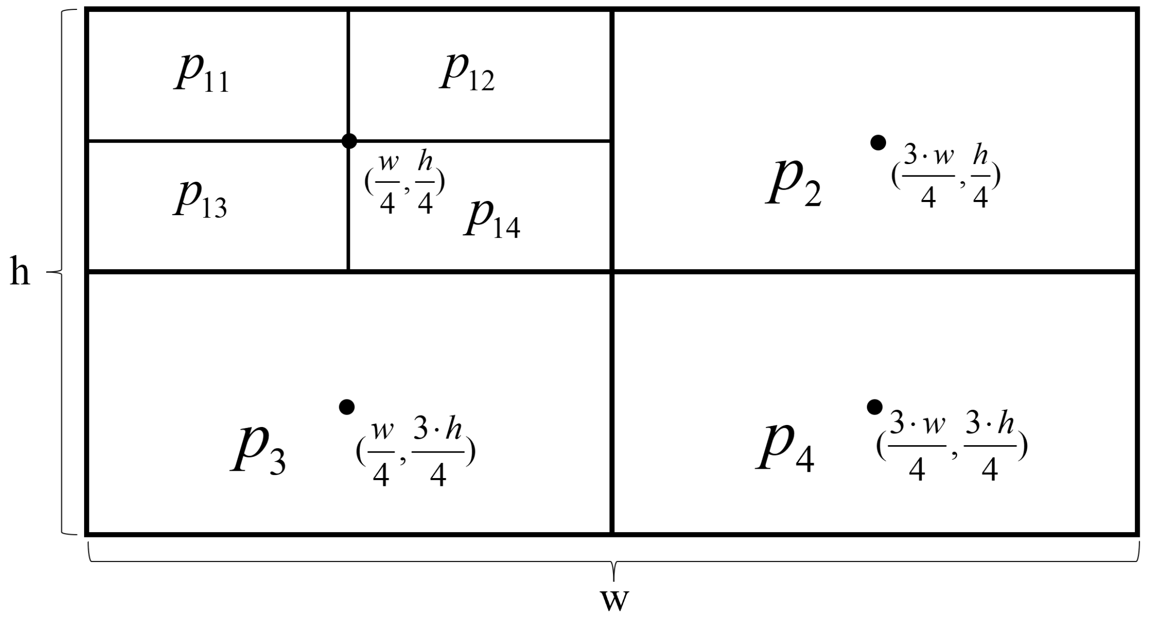
Repeat the above three steps to perform feature point extraction. Assuming the image has a pixel size of  w × h , regions are divided equally around pixel points  ( w 4 , h 4 ) , ( 3 · w 4 , h 4 ) ( w 4 , 3 · h 4 ) , and  ( 3 · w 4 , 3 · h 4 ) , in the upper left, bottom left, upper right, and bottom right directions, resulting in the following 16 regions:  p 11 , p 12 , p 13 p 44 . The specific arrangement is shown in Figure 3:
(5)
Let Y be the number of feature points obtained. If the number of feature points in the corresponding region is greater than G, all points are directly retained.
(6)
If the number of feature points in the corresponding region is equal to 0, adjust the pixel adaptive threshold, with  ε K  as the threshold and  ε  as the scaling factor. We set it at 0.5. If there are still no feature points after adjusting the threshold, detection is stopped.
(7)
The points obtained in the above steps are candidate feature points. They may exhibit edge clustering. We use non-maximum suppression to remove duplicates and filter the candidate feature points. This allows us to obtain the final set of feature points.
We have obtained the desired set of feature points through the aforementioned algorithm steps. Therefore, we will now proceed with the feature matching algorithm. However, due to the structural similarities in the space model we are dealing with, there still exist sets of feature points with similar attributes on the same epipolar line. As shown in Figure 4, the surrounding pixel information of points a, b, c, and d is extremely similar, making it difficult to distinguish them using the current algorithm. Correspondingly, in the right image, each of the points  a 1 b 1 c 1 , and  d 1  has similar pixel features. Hence, even under the constraint of the epipolar line, there will still be a possibility of point a being matched to any one of the points  a 1 b 1 c 1 , or  d 1 . The presence of these mis-matched points participating in the pose calculation process can severely impact the accuracy of the measurement algorithm. As the linear features of the spacecraft’s solar panels in space targets are abundant, we have developed the following matching algorithm to filter out non-matching feature point pairs. The specific algorithm steps are as follows:
(1)
First, compute the BRIEF descriptor for each feature point in the left image and right image to obtain the BRIEF descriptor vector of each feature point. Then, compare the BRIEF descriptor vector of a specific feature point in the left image with the BRIEF descriptor vectors of all feature points on the corresponding epipolar line in the right image. Calculate the Hamming distance between the descriptors and select the pair with the smallest distance as the correct match.
(2)
When all feature points in the left image have been traversed, we iterate through all corresponding feature points on the constrained epipolar line in the right image, based on the right image. We perform reverse matching, keeping the matches if they coincide and discarding them if they do not match.
To verify the effectiveness of the proposed point feature extraction and matching method, we collected a set of 30 pairs of stereo images in a darkroom with an illuminance of 1.2 lux, simulating the operation of a stereo camera in a real-world spatial environment. We chose the docking model of the Shenzhou 10 spacecraft, which has the advantage of stronger reflectivity and greater sensitivity of the solar panels to variations in light. We separately validated three algorithms on the constructed image dataset and calculated the average values of the extracted features in the images. The hardware used for this experiment consisted of an R7-6800H CPU, 16GB of memory, and the Windows 11 operating system. The final results are as Table 1:
Based on the specific performance comparison in Table 1 and Figure 5, our method exhibits stronger stability and robustness in low-light environments compared to the currently used algorithm that combines point and line feature extraction. Moreover, our method achieves higher matching efficiency and a lower mismatch rate. The inclusion of more abundant and accurate matching feature points greatly improves the stability of pose measurement methods for real-space tasks. Therefore, our proposed algorithm for point feature extraction and matching holds practical significance for various real-space pose measurement tasks.

3.3. Improved Line Feature Extraction and Matching Algorithm

To extract line features in an image, it is common to first compute the edge information present in the image. Then, the edge information is compared and matched between images to detect similar edges. Finally, valid line features are extracted from this edge information. In 2012, Von et al. introduced the Line Segment Detector (LSD) algorithm, which exhibits significant improvements in real-time performance and accuracy compared to traditional line detection methods. However, the accuracy of line detection is limited in practical spatial tasks due to variations in lighting conditions. Therefore, we have made improvements to the LSD algorithm by removing false lines and merging short lines. The specific steps of the improved line feature extraction and matching algorithm are as following:
(1)
Calculate the angle between pixels and pixels, and compute their corresponding gradients using the following formula, as Equations (3)–(6):
g x ( x , y ) = i ( x , y + 1 ) + i ( x + 1 , y + 1 ) i ( x , y ) i ( x + 1 , y ) 2
g y ( x , y ) = i ( x + 1 , y ) + i ( x + 1 , y + 1 ) i ( x , y ) i ( x , y + 1 ) 2
G ( x , y ) = g x 2 ( x , y ) + g y 2 ( x , y )
θ ( x , y ) = arctan ( g x ( x , y ) g y ( x , y ) )
g x ( x , y )  represents the gradient value in the horizontal direction,  g y ( x , y )  represents the gradient value in the vertical direction,  G ( x , y )  represents the total gradient value, and  θ ( x , y )  represents the gradient direction. In the equation,  i ( x , y )  represents the grayscale value of the pixel  ( x , y ) .
(2)
When all feature points in the left image have been traversed, we iterate through all corresponding feature points on the constrained epipolar line in the right image, based on the right image. We perform reverse matching, keeping the matches if they coincide and discarding them if they do not match.
(3)
If two line segments are non-parallel and  | a n g l e l 1 a n g l e l 2 | θ , they are considered as one line segment when the angle between them is smaller than the angle threshold.
(4)
If two line segments are parallel and one end of one line segment falls between the two ends of the other line segment, meaning the shortest distance between the two line segments does not exceed the distance threshold, they can be considered as one line segment.
(5)
The brute force matching algorithm is used to calculate the Hamming distance between the LBD descriptor of a certain valid line segment in the left image and the binary LBD feature descriptors of all valid line segments in the right image. The pair of valid line segments with the smallest Hamming distance value is determined as the preliminary matching feature segments.
(6)
The nearest and second nearest distance ratio method is used for fine matching to eliminate false matches and obtain precise matching feature segments.
In order to validate the effectiveness of our proposed line feature extraction and matching method, we continue to use the aforementioned simulated stereo camera to work in a real-world spatial environment and obtain the final results as shown in Table 2 and Figure 6:

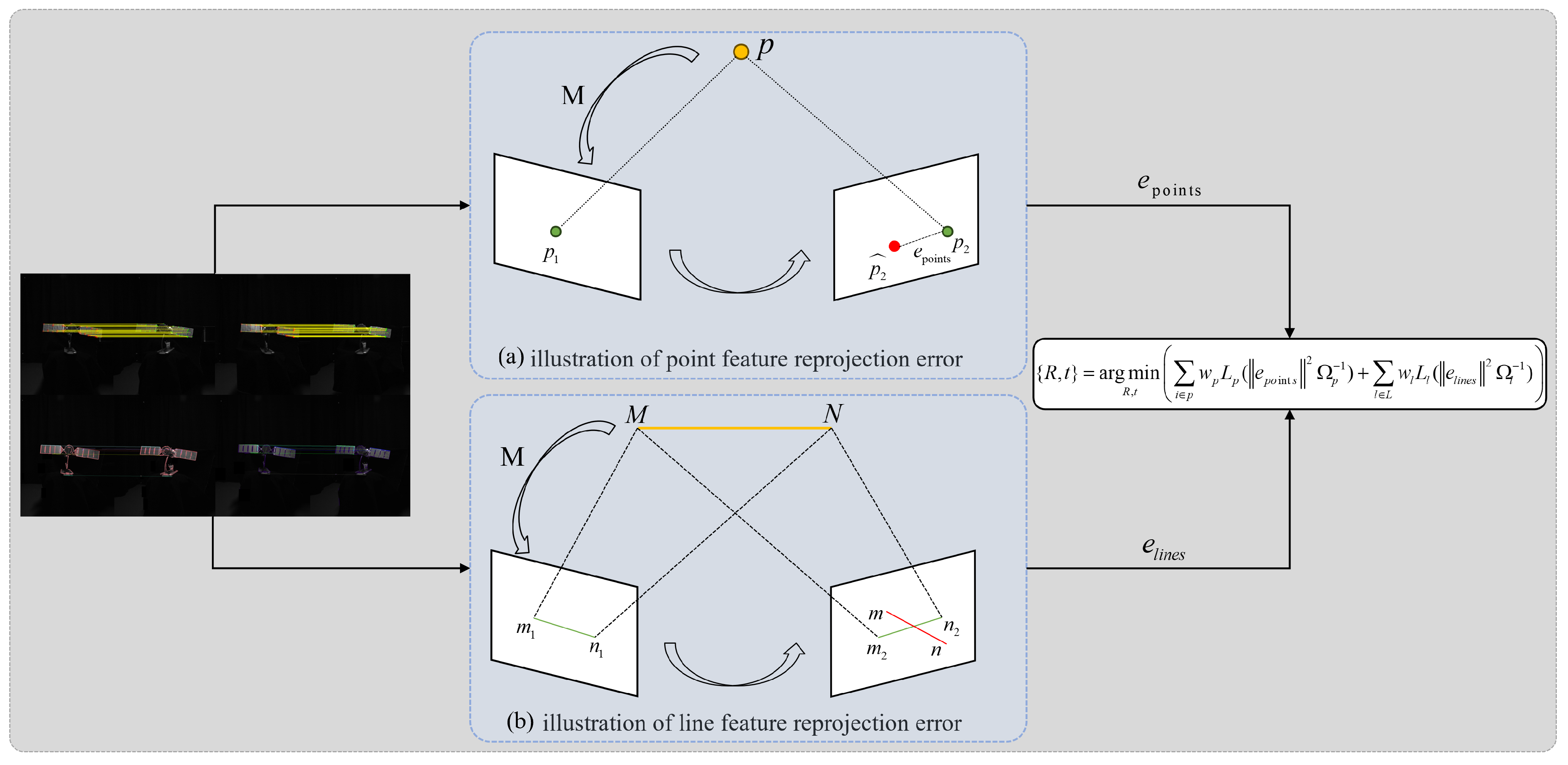
3.4. Pose Estimation

By utilizing the principles of a binocular vision system, we can compute the pose of a non-cooperative target. The three-dimensional coordinates in the world coordinate system can be solved using the following formula:
X w = Z w u l f l
Y w = Z w v l f l
Z w = f l ( f r t x u r t z ) u r ( r 7 u l + r 8 v l + f l r 9 ) f r ( r 1 u l + r 2 v l + f l r 3 )
In this case, the left camera has a focal length of  f l , and the right camera has a focal length of  f r ( u l , v l )  represents the pixel coordinates of the projection point in the left camera, and  ( u r , v r )  represents the pixel coordinates of the projection point in the right camera.
θ x = arctan ( r 8 , r 9 )
θ y = arctan ( r 7 , r 8 2 + r 9 2 )
θ z = arctan ( r 4 , r 1 )
We use  θ x θ y , and  θ z  to measure the angles of rotation around the three axes.  θ x  represents the angle of rotation around the x-axis,  θ y  represents the angle of rotation around the y-axis, and  θ z  represents the angle of rotation around the z-axis.
Due to the inevitable presence of certain errors in the extraction of point and line features, the accuracy of the final pose measurement is not sufficiently high. Therefore, we not only improve the algorithm for point and line feature extraction and matching, but also construct an error model in the final pose estimation stage to reduce the errors in pose measurement. We first construct re-projection error models for point and line features separately to perform initial pose optimization. Then, we further enhance the accuracy of the final pose estimation by fusing the point and line features using an adaptive weighting based on illumination. The specific algorithm diagram is shown in Figure 7:
In Figure 7 p 1  and  p 2  are the projected coordinates of point P in the left and right cameras, respectively, in the world coordinate system.  p 2 ^  is the calculated error position, and the distance between  p 2  and  p 2 ^  corresponds to the re-projection error of the point. We need to optimize through iterative methods to minimize this distance.
For the re-projection error of point features, the relationship between the world coordinate system and the pixel coordinate system can be obtained through the Lie algebra relationship as follows:
s i u i v i 1 = KT X i Y i Z i 1
In matrix form, it can be expressed as:
s i p i = KT P i
Among them, K is the intrinsic matrix of the camera and T is the transformation matrix from the world coordinate system to the camera coordinate system. By constructing a least squares problem, we can obtain the solution. By constructing the least squares problem, we can obtain:
T * = arg min T 1 2 i = 1 n | | p i 1 s i K T P i | | 2
For the line feature error model, due to its higher dimensionality, it cannot be represented simply with three-dimensional coordinates. Instead, the two-point line principle can be used to represent the line using two spatial points, as shown in the figure. Line  m 1 n 1  represents the projected line in the left image, while line  m 2 n 2  represents the projected line in the right image. The actual line is  m n , but it does not coincide with  m 2 n 2 m 2  and  n 2  are the two endpoints of  m 2 n 2 . The distance between  m 2  and  n 2  to  m n  is used to represent the reprojection error.
E l i n e = d ( m n , m 2 n 2 ) = m 2 T · m n m 2 + n 2 , n 2 T · m n m 2 + n 2 T
Similar to point features, for line features, we calculate the final line projection error. We use PnP to initialize the target pose and, at the same time, we allocate weights to point features and line features. Finally, we obtain the optimal solution by minimizing a cost function.
T = { R , t } = arg min R , t i p w p L p ( E p o i n t i 2 Ω p 1 ) + l L w l L l ( E l i n e i 2 Ω l 1 )
Ω p 1  and  Ω l 1  are the covariance matrices for points and lines, respectively.  w p  and  w l  are the weight functions based on lighting.
{ R , t }  represents the current optimal pose, p and L are the sets of matched point features and matched line segment features respectively.  e p o i n t i  and  e l i n e i  denote the current matching errors.  w p  and  w l  are the fusion weights for point features and line features, respectively, which are obtained by weighting the preliminary pose fusion of refined matching point features and refined matching line segment features based on the variations in lighting conditions. The specific values are derived from changes in illumination. Based on the characteristics of feature extraction, when the lighting is strong, the weight for point features is increased, and when the lighting is weak, the weight for line features is enhanced. The method is set as Equations (18) and (19), where n is a threshold value, set to 80 based on the space lighting environment, and N represents the number of extracted and successfully matched point features.
w p = e 1 N n N n ; 1 e 1 N n N < n ;
w l = 1 e 1 N n N n ; e 1 N n N < n ;

4. Physical Experiment Results

4.1. Experimental Environment

To validate the effectiveness of our proposed method, we conducted comparative simulation experiments under normal lighting conditions and low-light environments. We used a stereo camera with a resolution of 2048 × 2048 pixels and a baseline length of 38 cm. The target was stationary on a turntable, and the stereo camera moved at a speed of 1 cm/s from a distance of 141 cm, capturing one frame per second. Our algorithm was applied to process each captured frame. The specific experimental setup is shown in Figure 8.

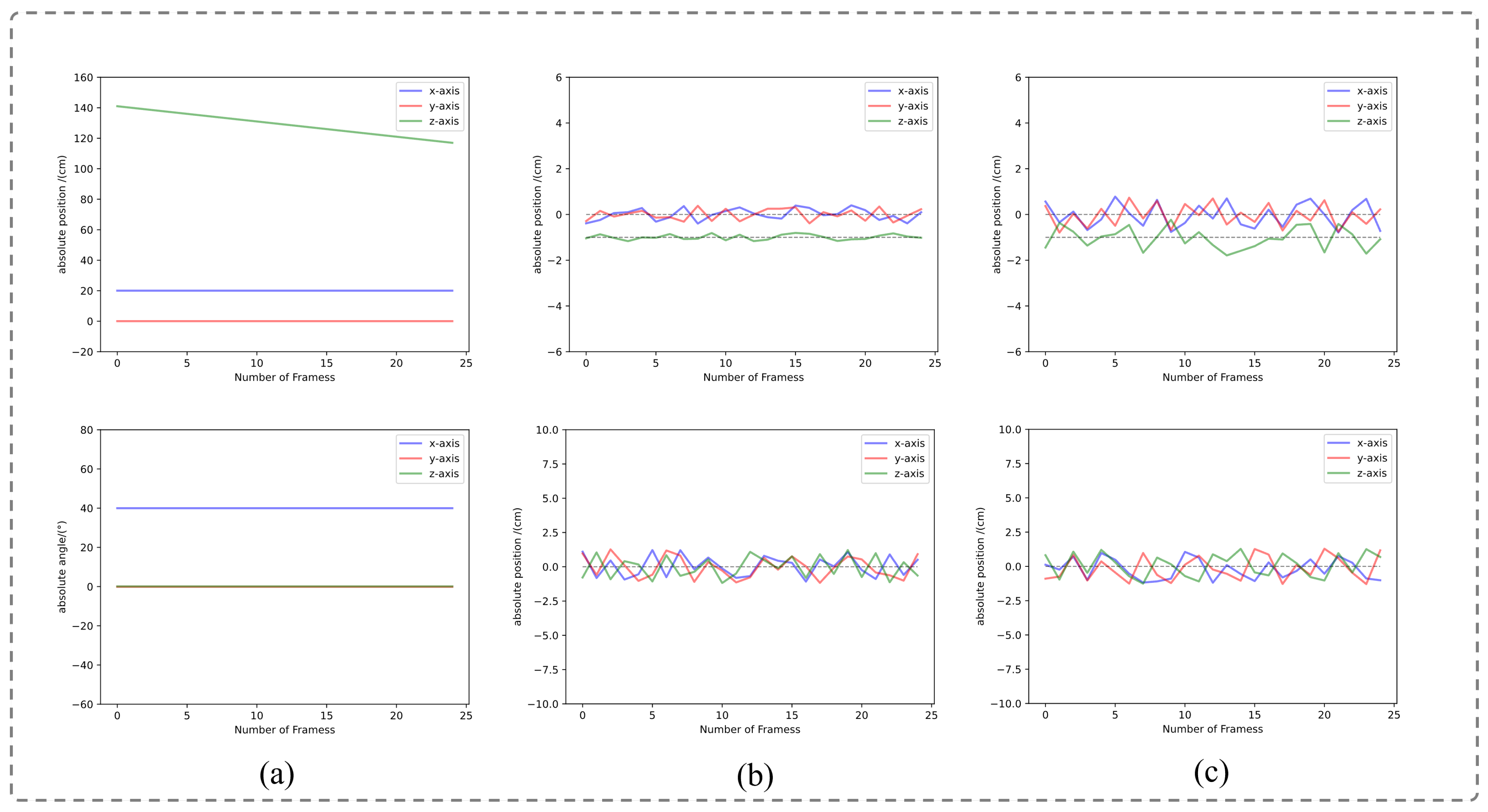
4.2. Analysis of Experimental Results

In order to provide a better comparison, we conducted control experiments in both a well-lit environment and a low-light environment with an illuminance of 1.2 lux, representing the two most extreme lighting conditions in space applications. These experiments were aimed at validating the practicality of our method. Figure 9a shows the experimental setup for our reference group. We moved the binocular camera uniformly along the Z-axis, resulting in a slanted straight line motion trajectory. The X and Y axes remained parallel to the horizontal axis, while the angle variation followed a horizontal line parallel to the horizontal axis, conforming to the motion pattern.
To represent the relative poses between non-cooperative targets, we calculated the differences between consecutive frames. As shown in Figure 9b, in a well-lit environment, our algorithm produced relatively stable relative poses for the non-cooperative targets. Specifically, the errors in the X and Y axes were mostly within 0.4 cm, and the error in the Z axis was within 0.2 cm. The attitude angle error was within 1.3 degrees. In summary, our algorithm exhibited stronger stability and higher accuracy in output results under good lighting conditions.
Figure 9c illustrates the results in a low-light environment, where we observed higher errors in the relative position and relative pose of the measured non-cooperative targets compared to the well-lit environment. The errors in all three axes were within 0.8 cm, and the errors in the three types of attitude angles were within 1.3 degrees.
Although control experiments were conducted in other lighting conditions, only the results for the well-lit environment and the worst lighting environment were presented in this paper due to space limitations.
The experimental results indicate that the degradation of localization accuracy under low-light conditions primarily stems from three interrelated factors. First, the significantly reduced signal-to-noise ratio (SNR) in low-illumination environments critically compromises the stability of feature extraction, particularly for high-frequency texture features, leading to decreased keypoint detection accuracy and consequently increasing uncertainty in pose estimation. Second, the inherent nonlinear noise characteristics under photon-limited imaging conditions introduce systematic biases, making gradient directions more susceptible to noise perturbations. Third, error propagation in pose estimation becomes more sensitive to outlier matches in low-light scenarios. Notably, the relative stability of Z-axis estimation benefits from the inherent baseline constraints in stereo vision systems. In contrast, errors in the X/Y axes are further exacerbated due to their correlation with the non-uniform distribution of planar features.

5. Conclusions

This paper proposes a real-time binocular vision pose estimation method for low-light environments. First, images are captured using a binocular camera, and the images are preprocessed based on the fixed parameters of the camera. Then, an adaptive improved feature extraction algorithm based on lighting conditions is applied, combining point feature matching with epipolar constraints to reduce the matching range from two dimensions to the epipolar direction, significantly improving matching speed and accuracy. Further, line features are introduced based on spacecraft structural information and processed in parallel with point features, greatly enhancing the accuracy of pose estimation results. Finally, an adaptive weighted multi-feature pose fusion algorithm based on lighting conditions is proposed to obtain the optimal pose estimation result. The method is validated through experiments on a self-built platform. Under good lighting conditions, the errors in the x and y coordinates are mainly controlled within 0.4 cm, the z-axis error is controlled within 0.2 cm, and the attitude angle error is less than 1.3°. In low-light environments, the three-axis coordinate errors are all below 0.8 cm, and the attitude angle error is less than 1.3°. The results meet the expected performance and can satisfy the needs of aerospace applications. However, there are still limitations, such as degradation of feature extraction in extremely low-light conditions and insufficient dynamic lighting adaptability. Future work will explore methods for pose detection using other inherent structural features of non-cooperative spacecraft to extend the applicability and stability of the measurement results in complex lighting scenarios, such as deep space exploration and non-cooperative target measurement, providing more robust pose perception support for space intelligent autonomous systems.

Author Contributions

Conceptualization, H.Z.; methodology, H.Z. and J.W.; software, D.L., H.A., and M.X.; validation, D.L.; investigation, H.Z.; writing—original draft preparation, C.M.; writing—review and editing, H.Z. and D.L.; funding acquisition, H.Z. All authors have read and agreed to the published version of the manuscript.

Funding

This research was funded by the Shaanxi provincial fund 2023—YBGY—234.

Data Availability Statement

Data underlying the results presented in this paper are not publicly available at this time but may be obtained from the authors upon reasonable request.

Conflicts of Interest

The authors declare no conflicts of interest.

References

  1. Wang, F.; Zhang, H.; Zhang, G.; Shan, F.; Ren, L.; Ai, H.; Cao, J. High-precision pose measurement method based on binocular vision in dark lighting environments. Opt. Eng. 2023, 62, 024105. [Google Scholar] [CrossRef]
  2. Pan, H.; Huang, J.; Qin, S. High accurate estimation of relative pose of cooperative space targets based on measurement of monocular vision imaging. Optik 2014, 125, 3127–3133. [Google Scholar] [CrossRef]
  3. Zhang, Y.; Qin, S.; Hu, X. High-precision and real-time algorithms of multi-object detection, recognition and localization toward ARVD of cooperative spacecrafts. Optik 2015, 126, 5797–5805. [Google Scholar] [CrossRef]
  4. Liu, Z.; Liu, H.; Zhu, Z.; Sun, C.; Song, J. Three-dimensional shape reconstruction of uncooperative spacecraft with texture-guided depth upsampling. Meas. Sci. Technol. 2021, 32, 095006. [Google Scholar] [CrossRef]
  5. Zhao, G.; Xu, S.; Bo, Y. LiDAR-Based Non-Cooperative Tumbling Spacecraft Pose Tracking by Fusing Depth Maps and Point Clouds. Sensors 2018, 18, 3432. [Google Scholar] [CrossRef]
  6. Capuano, V.; Kim, K.; Harvard, A.; Chung, S.J. Monocular-based pose determination of uncooperative space objects. Acta Astronaut. 2020, 166, 493–506. [Google Scholar] [CrossRef]
  7. Peng, J.; Xu, W.; Yan, L.; Pan, E.; Liang, B.; Wu, A.G. A Pose Measurement Method of a Space Noncooperative Target Based on Maximum Outer Contour Recognition. IEEE Trans. Aerosp. Electron. Syst. 2020, 56, 512–526. [Google Scholar] [CrossRef]
  8. Sharma, S.; Beierle, C.; D’Amico, S. Pose estimation for non-cooperative spacecraft rendezvous using convolutional neural networks. In Proceedings of the 2018 IEEE Aerospace Conference, Big Sky, MO, USA, 3–10 March 2018; pp. 1–12. [Google Scholar] [CrossRef]
  9. Huan, W.; Liu, M.; Hu, Q. Pose Estimation for Non-cooperative Spacecraft based on Deep Learning. In Proceedings of the 2020 39th Chinese Control Conference (CCC), Shenyang, China, 27–29 July 2020; pp. 3339–3343. [Google Scholar] [CrossRef]
  10. Pauly, L.; Rharbaoui, W.; Shneider, C.; Rathinam, A.; Gaudillière, V.; Aouada, D. A survey on deep learning-based monocular spacecraft pose estimation: Current state, limitations and prospects. Acta Astronaut. 2023, 212, 339–360. [Google Scholar] [CrossRef]
  11. Davis, J.; Pernicka, H. Proximity operations about and identification of non-cooperative resident space objects using stereo imaging. Acta Astronaut. 2019, 155, 418–425. [Google Scholar] [CrossRef]
  12. De Jongh, W.; Jordaan, H.; Van Daalen, C. Experiment for pose estimation of uncooperative space debris using stereo vision. Acta Astronaut. 2020, 168, 164–173. [Google Scholar] [CrossRef]
  13. Jiang, C.; Hu, Q. Constrained Kalman filter for uncooperative spacecraft estimation by stereovision. Aerosp. Sci. Technol. 2020, 106, 106133. [Google Scholar] [CrossRef]
  14. Pasqualetto Cassinis, L.; Fonod, R.; Gill, E. Review of the robustness and applicability of monocular pose estimation systems for relative navigation with an uncooperative spacecraft. Prog. Aerosp. Sci. 2019, 110, 100548. [Google Scholar] [CrossRef]
  15. Sun, D.; Hu, L.; Duan, H.; Pei, H. Relative Pose Estimation of Non-Cooperative Space Targets Using a TOF Camera. Remote Sens. 2022, 14, 6100. [Google Scholar] [CrossRef]
  16. Gómez Martínez, H.; Giorgi, G.; Eissfeller, B. Pose estimation and tracking of non-cooperative rocket bodies using Time-of-Flight cameras. Acta Astronaut. 2017, 139, 165–175. [Google Scholar] [CrossRef]
  17. Peng, J.; Xu, W.; Liang, B.; Wu, A.G. Pose Measurement and Motion Estimation of Space Non-Cooperative Targets Based on Laser Radar and Stereo-Vision Fusion. IEEE Sens. J. 2019, 19, 3008–3019. [Google Scholar] [CrossRef]
  18. Liu, Q.; Tang, X.; Huo, J. Attitude measurement of ultraclose-range spacecraft based on improved YOLOv5s and adaptive Hough circle extraction. Appl. Opt. 2024, 63, 1364–1376. [Google Scholar] [CrossRef]
  19. Wang, F.; Xu, W.; Yan, L.; Xie, C.; Pu, W. Rectangular Natural Feature Recognition and Pose Measurement Method for Non-Cooperative Spacecraft. Aerospace 2024, 11, 125. [Google Scholar] [CrossRef]
  20. Yuan, H.; Chen, H.; Wu, J.; Kang, G. Non-Cooperative Spacecraft Pose Estimation Based on Feature Point Distribution Selection Learning. Aerospace 2024, 11, 526. [Google Scholar] [CrossRef]
  21. Gao, X.; Yu, J.; Tan, M. An Online 3D Modeling Method for Pose Measurement under Uncertain Dynamic Occlusion Based on Binocular Camera. Sensors 2023, 23, 2871. [Google Scholar] [CrossRef]
  22. Fischler, M.A.; Bolles, R.C. Random Sample Consensus: A Paradigm for Model Fitting with Applications to Image Analysis and Automated Cartography. In Readings in Computer Vision; Fischler, M.A., Firschein, O., Eds.; Morgan Kaufmann: San Francisco, CA, USA, 1987; pp. 726–740. [Google Scholar] [CrossRef]
  23. Strutz, T. Data Fitting and Uncertainty: A Practical Introduction to Weighted Least Squares and Beyond; Vieweg+Teubner: Wiesbaden, Germany, 2010. [Google Scholar]
  24. Legrand, A.; Detry, R.; Vleeschouwer, C.D. End-to-end Neural Estimation of Spacecraft Pose with Intermediate Detection of Keypoints. In Proceedings of the ECCV Workshops, Tel Aviv, Israel, 23–27 October 2022. [Google Scholar]
  25. Lepetit, V.; Moreno-Noguer, F.; Fua, P. EPnP: An accurate O(n) solution to the PnP problem. Int. J. Comput. Vis. 2009, 81, 155–166. [Google Scholar] [CrossRef]
  26. Kleeberger, K.; Huber, M.F. Single Shot 6D Object Pose Estimation. In Proceedings of the 2020 IEEE International Conference on Robotics and Automation (ICRA), Paris, France, 31 May–31 August 2020; pp. 6239–6245. [Google Scholar] [CrossRef]
  27. Chen, B.; Cao, J.; Parra, Á.; Chin, T.J. Satellite Pose Estimation with Deep Landmark Regression and Nonlinear Pose Refinement. In Proceedings of the 2019 IEEE/CVF International Conference on Computer Vision Workshop (ICCVW), Seoul, Republic of Korea, 27–28 October 2019; pp. 2816–2824. [Google Scholar]
  28. Kendall, A.; Cipolla, R. Geometric Loss Functions for Camera Pose Regression with Deep Learning. In Proceedings of the 2017 IEEE Conference on Computer Vision and Pattern Recognition (CVPR), Honolulu, HI, USA, 21–26 July 2017; pp. 6555–6564. [Google Scholar] [CrossRef]
  29. Szegedy, C.; Liu, W.; Jia, Y.; Sermanet, P.; Reed, S.; Anguelov, D.; Erhan, D.; Vanhoucke, V.; Rabinovich, A. Going deeper with convolutions. In Proceedings of the 2015 IEEE Conference on Computer Vision and Pattern Recognition (CVPR), Boston, MA, USA, 7–12 June 2015; pp. 1–9. [Google Scholar] [CrossRef]
  30. Park, T.H.; D’Amico, S. Robust Multi-Task Learning and Online Refinement for Spacecraft Pose Estimation across Domain Gap. arXiv 2022, arXiv:2203.04275. [Google Scholar] [CrossRef]
  31. Garcia, A.; Musallam, M.A.; Gaudilliere, V.; Ghorbel, E.; Al Ismaeil, K.; Perez, M.; Aouada, D. LSPnet: A 2D Localization-oriented Spacecraft Pose Estimation Neural Network. In Proceedings of the 2021 IEEE/CVF Conference on Computer Vision and Pattern Recognition Workshops (CVPRW), Nashville, TN, USA, 19–25 June 2021; pp. 2048–2056. [Google Scholar] [CrossRef]
  32. Musallam, M.A.; Gaudillière, V.; Del Castillo, M.O.; Al Ismaeil, K.; Aouada, D. Leveraging Equivariant Features for Absolute Pose Regression. In Proceedings of the 2022 IEEE/CVF Conference on Computer Vision and Pattern Recognition (CVPR), New Orleans, LA, USA, 18–24 June 2022; pp. 6866–6876. [Google Scholar] [CrossRef]
  33. Leon, V.; Lentaris, G.; Soudris, D.; Vellas, S.; Bernou, M. Towards Employing FPGA and ASIP Acceleration to Enable Onboard AI/ML in Space Applications. In Proceedings of the 2022 IFIP/IEEE 30th International Conference on Very Large Scale Integration (VLSI-SoC), Patras, Greece, 3–5 October 2022; pp. 1–4. [Google Scholar] [CrossRef]
  34. Cai, H. Experiment Research of Non-cooperative Space Target Relative Measurement Based on Binocular Vision. Master’s Thesis, Beijing Institute of Technology, Beijing, China, 2015. [Google Scholar]
  35. Zhao, Z.Q. Research on Key Technologies of Visual Pose Measurement System with Large Vision Range for Non-cooperative Target. Ph.D. Thesis, Harbin Institute of Technology, Harbin, China, 2016. [Google Scholar]
  36. Wen, H.; Tian, J.; Li, D. PLS-VIO: Stereo Vision-inertial Odometry Based on Point and Line Features. In Proceedings of the 2020 International Conference on High Performance Big Data and Intelligent Systems, Shenzhen, China, 23 May 2020; pp. 1–7. [Google Scholar] [CrossRef]
Figure 1. Schematic diagram of the binocular pose measurement model. The origin of the left camera coordinate system is  O c l , and the origin of the right camera coordinate system is  O c r . The transformation matrix from the world coordinate system to the camera coordinate system is “M”, the transformation matrix between the left and right cameras is “N”, and the origin of the world coordinate system is  O c w .
Electronics 14 01795 g001
Figure 2. Flowchart of our point-line feature fusion algorithm. Stereo images undergo parallel point and line feature extraction and matching, followed by weighted fusion using a designed algorithm to obtain the optimal final pose.
Electronics 14 01795 g002
Figure 3. Incorporation of a quadtree-based region search method to mitigate instability caused by rich image textures, thereby enhancing the quality of point features in the images.
Electronics 14 01795 g003
Figure 4. Schematic diagram of similar point matching in left and right images. Points a, b, c, and d in the left image exhibit highly similar surrounding pixel information, making them challenging to distinguish under the current algorithm. Corresponding points  a 1 b 1 c 1 , and  d 1  in the right image also share analogous pixel characteristics.
Electronics 14 01795 g004
Figure 5. We collected a dataset of 30 stereo image pairs in a darkroom with 1.2 lux illumination, simulating the working environment of binocular cameras under real-space conditions. Using the Shenzhou-11 spacecraft docking model as our subject, we validated the performance of our algorithm on the constructed image dataset. The figure demonstrates the practical extraction and matching results of our algorithm applied to the docking model images.
Electronics 14 01795 g005
Figure 6. To validate the effectiveness of our improved line feature extraction and matching method, we utilized the same set of 30 stereo image pairs aligned with real-space conditions to simulate the binocular camera scenario. The verification results of our enhanced feature extraction and matching algorithm are illustrated in the figure.
Electronics 14 01795 g006
Figure 7. Since both point and line feature extraction methods may introduce a certain degree of error, leading to suboptimal pose measurement accuracy, we not only enhanced the point-line feature extraction and matching algorithms but also developed an error model in the final pose-solving stage to reduce measurement errors. Specifically, we first developed reprojection error models for point and line features respectively to perform preliminary pose optimization. Subsequently, we fused the point-line features using an illumination-based adaptive weighting method to further improve the final pose estimation accuracy. A schematic diagram of this algorithm is shown in the figure, where the left panel demonstrates the effectiveness of point and line feature extraction and matching.
Electronics 14 01795 g007
Figure 8. Schematic diagram of our darkroom experimental setup, comprising a 2D turntable, 3D turntable, mobile sliding rail, and a binocular camera system.
Electronics 14 01795 g008
Figure 9. Line chart of the final pose estimation algorithm performance. Under good illumination, x- and y-axis coordinate errors are primarily within 0.4 cm, z-axis error within 0.2 cm, and attitude angle error below 1.3°. In low-illumination environments, three-axis coordinate errors remain below 0.8 cm with attitude angle error under 1.3°.
Electronics 14 01795 g009
Table 1. Our proposed algorithm, compared to the traditional ORB algorithm and Wang’s algorithm, shows superior performance in the end.
Extracted PointsMatches Points (Pairs)Mismatch RateTime (s)
Wang’s algorithm1230535.4%0.229
ORB algorithm14331499.1%0.427
Our algorithm19731063.7%0.552
Table 2. Our proposed algorithm, compared to the traditional LSD + LBD, shows superior performance in the end.
Extracted LinesMatches Lines (Pairs)Mismatch RateTime(s)
LSD + LBD3161811.5%0.634
Our algorithm154136.1%0.671
Disclaimer/Publisher’s Note: The statements, opinions and data contained in all publications are solely those of the individual author(s) and contributor(s) and not of MDPI and/or the editor(s). MDPI and/or the editor(s) disclaim responsibility for any injury to people or property resulting from any ideas, methods, instructions or products referred to in the content.

