

Dual-Random Space Vector Pulse Width Modulation Strategy Based on Optimized Beta Distribution


Abstract
1. Introduction
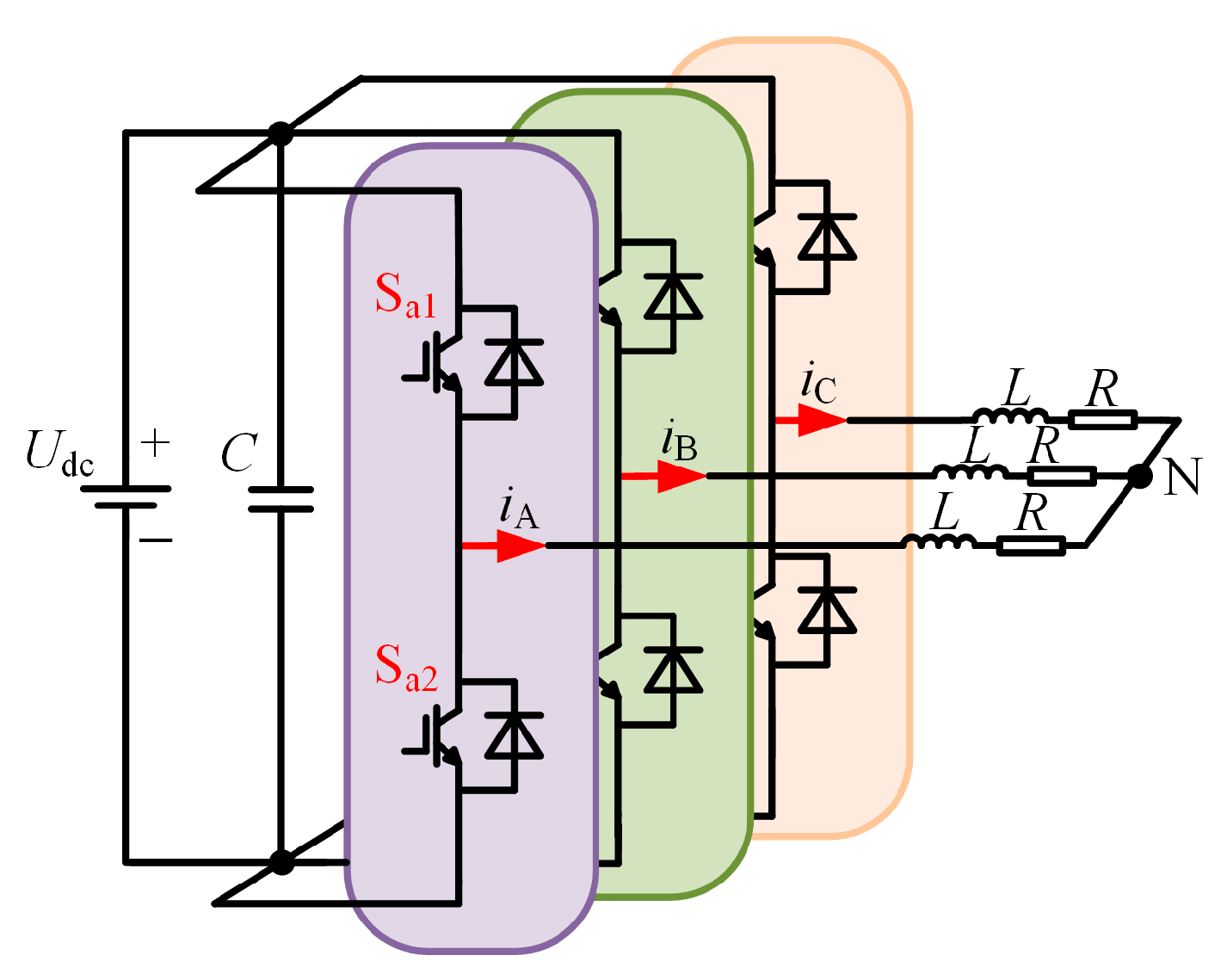
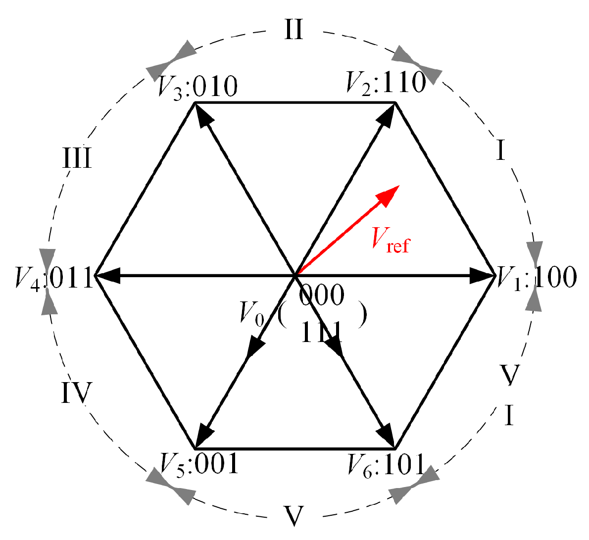
2. Topology of Two-Level Inverter and Principles of Its Modulation Strategy
3. Conventional Dual-Random SVPWM Strategy
3.1. RZVPWM Strategy
3.2. RSFPWM Strategy
4. Optimization of Random Numbers
4.1. Method Overview
4.2. The Influence of Different Shape Parameters on the Distribution of Random Numbers
- (1)
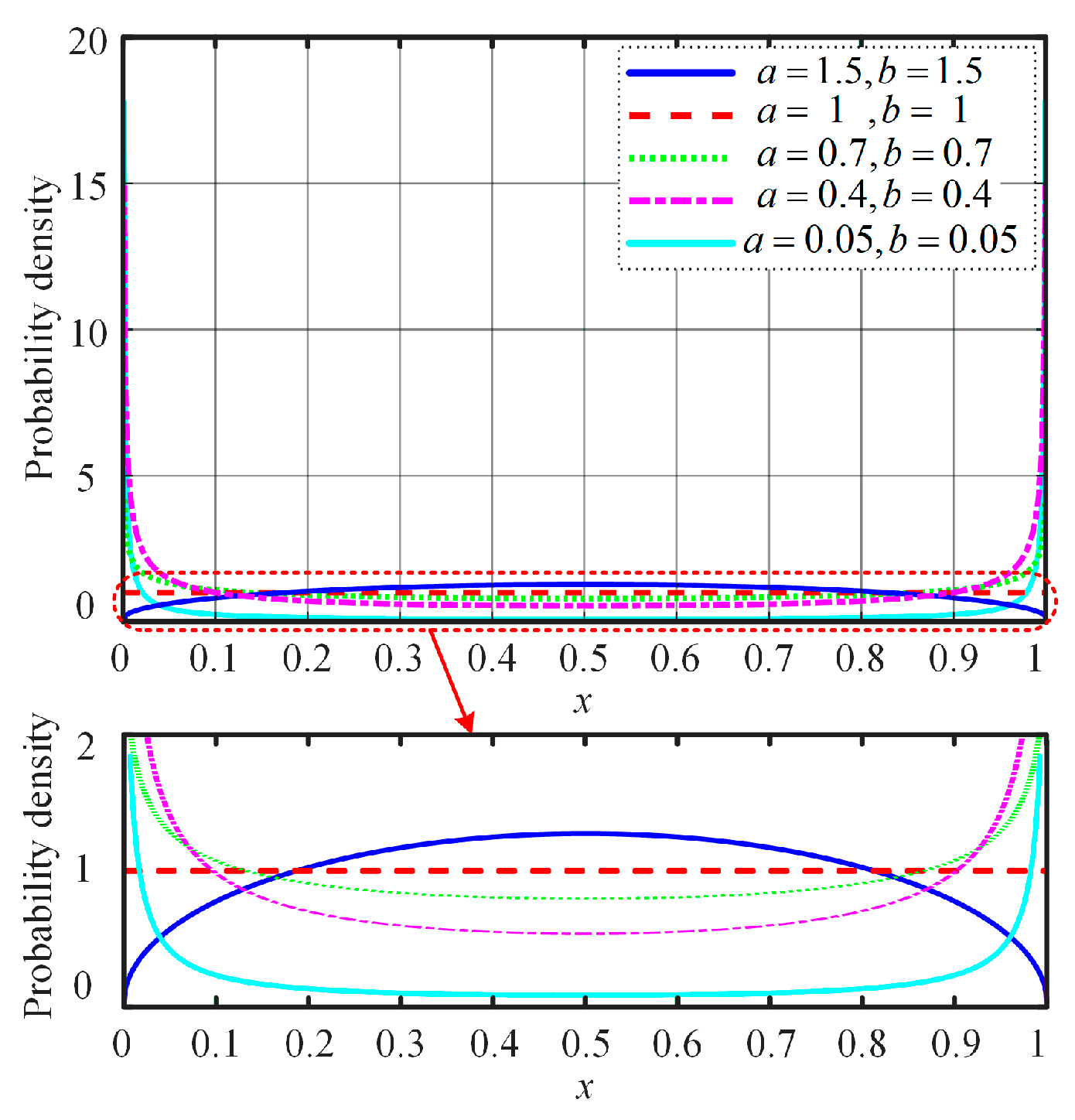
- When a = b, the random number distribution exhibits a high degree of symmetry centered around the expected value of 0.5, a characteristic derived from the mathematical properties of the Beta distribution under parameter symmetry.
- (2)
- When a ≠ b, the random number distribution displays asymmetry, with its probability density function becoming imbalanced near the expected value of 0.5, skewing toward the side with the larger parameter.
4.3. Shape Parameter Optimization Based on PSO Algorithm
- (1)
- Calibration of initial system parameters: Based on the phase current data collected from experiments, calibrate parameters such as winding inductance and resistance in the simulation model to ensure that the simulation model aligns with experimental results under various operating conditions.
- (2)
- Initialize the particle swarm: Restrict the particle range to 0.01~2. Each particle in the swarm contains basic information, namely the shape parameters a and b. During each iteration, the individual best solution Pbest of each particle is compared and updated with the global best solution Gbest. Since this study involves an optimization problem with only two parameters, a population of 20 particles is sufficient to cover the solution space, providing adequate diversity to avoid premature convergence to suboptimal solutions. Additionally, the maximum number of iterations is chosen as the convergence criterion, with 60 iterations allowing the algorithm sufficient time to refine the solution. A dynamic inertia weight strategy is adopted, with the weight value linearly decreasing from 0.9 to 0.4 during the iteration process. A larger weight in the early stages ensures a strong global search capability, while a smaller weight in the later stages enhances the local search capability. The learning factors are set to c1 = c2 = 2.0, achieving a balance between individual experience and collective collaboration, thus preventing premature convergence to local optima.
- (3)
- Run the steady-state condition Simulink simulation program, generate the phase current time-domain waveform data in the MATLAB (Version: 9.5.0.944444, R2018b) (MathWorks, Inc., Natick, MA, USA) workspace, and then perform time-frequency conversion on the data using the fast Fourier transform (FFT) program, followed by calculating the HSF, and finally, extract the individual optimal solution Pbest and the global optimal solution Gbest.
- (4)
- Termination condition setting: In the conventional PSO algorithm, termination conditions typically include the number of iteration steps and convergence criteria. To ensure population diversity, this paper uses the number of iteration steps as the termination condition to prevent premature convergence or excessive iteration without convergence of the particle swarm.
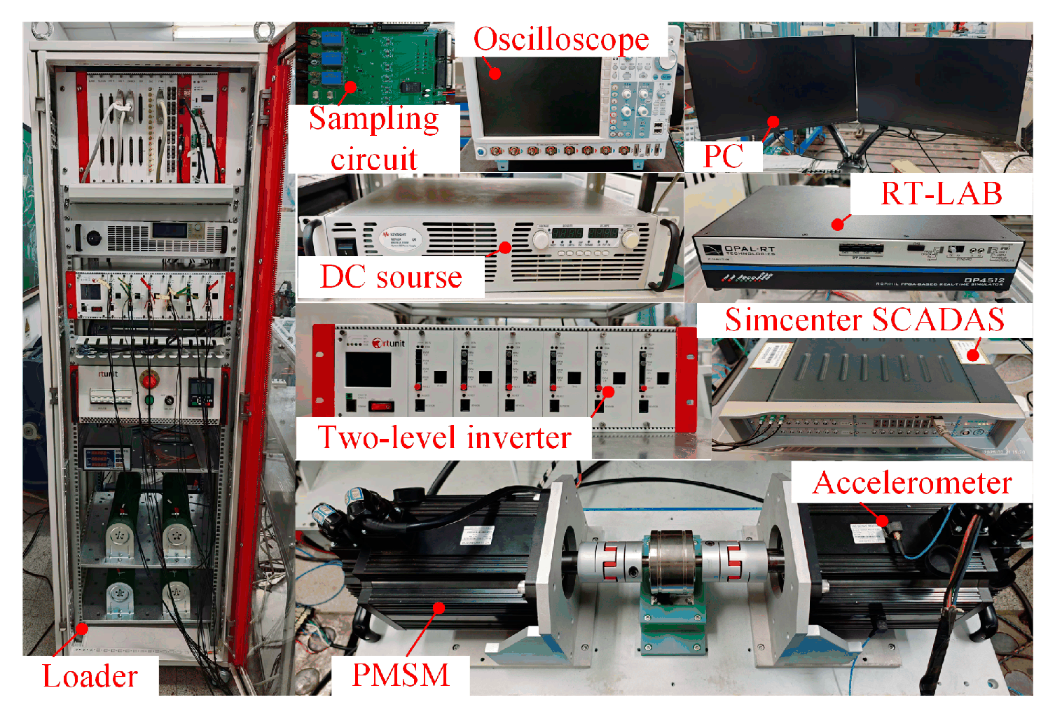
5. Experimental Results
6. Discussion
7. Conclusions
- (1)
- To address the high-frequency vibration issue in conventional SVPWM strategies caused by a constant switching frequency and fixed zero-vector allocation time, randomization of the switching frequency and zero-vector allocation time is proposed to reduce high-frequency vibrations in PMSM.
- (2)
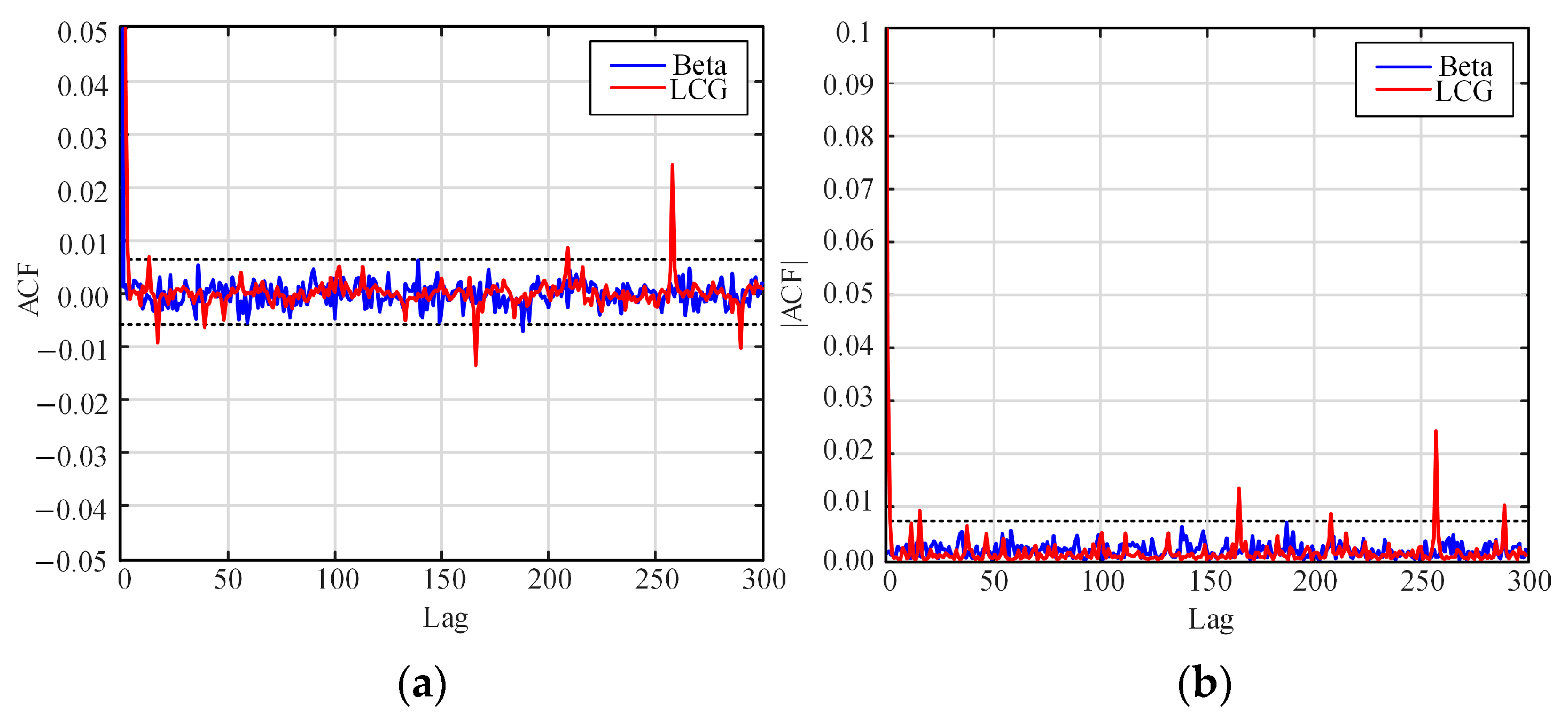
- To address the issues of poor randomness and short periodicity of random numbers generated by the LCG algorithm in conventional dual-random SVPWM strategies, the use of the Beta distribution for random number generation is proposed to improve the quality of random numbers.
- (3)
- To address the inefficiency of using enumeration methods to find optimal shape parameters in traditional Beta distribution-based random number generation, a PSO algorithm is proposed to rapidly optimize shape parameters, thereby improving efficiency.
Author Contributions
Funding
Data Availability Statement
Conflicts of Interest
References
- Jang, I.S.; Kim, W.H. Study on Electromagnetic Vibration Analysis Process for PM Motors. IEEE Transactions on Applied Superconductivity. IEEE Trans. Appl. Supercond. 2020, 30, 1–6. [Google Scholar]
- Chen, Y.; Qiu, Z.Z.; Ma, K.; Kong, Z.G.; Huang, X. Investigation into Markov-chain random modulation for suppression high-frequency sideband vibro-acoustics in permanent magnet synchronous motor. Electr. Mach. Control. 2023, 27, 109–118. [Google Scholar]
- Dong, L.J.; Pan, Z.L.; Li, S.; Li, Y.; Duan, H. Micromotors Study on Regulation and Voltage Utilization Ratio of SPWM and SVPWM Schemes for Vehicle Motor. Micromotors 2023, 56, 49–52. [Google Scholar]
- Li, F.T.; Zhang, C.X.; Pang, Y. Analysis and Optimization of Electromagnetic Vibration and Noise of Permanent Magnet Synchronous Motor. Small Spec. Electr. Mach. 2024, 52, 27–32. [Google Scholar]
- Li, Y.Z.; Wu, S.N. Methods for Vibration and Noise Reduction of IPMSM. Small Spec. Electr. Mach. 2024, 52, 25–29. [Google Scholar]
- Xu, J.; Ouyan, Z.; Sun, J.; Zhu, W.; Nie, Z. Performance and Characterization of Optimal Harmonic Dispersion Effect in Double Frequency-Band Random PWM Strategy. IEEE Trans. Power Electron. 2024, 39, 14680–14690. [Google Scholar] [CrossRef]
- Zhang, P.; Wang, S.; Li, Y. Generalized N-State Random Pulse Position Discontinuous PWM for High-Frequency Harmonics Reduction and Performance Improvement at High Modulation Ratios. IEEE Trans. Power Electron. 2024, 39, 13659–13671. [Google Scholar] [CrossRef]
- Qiu, Z.Z.; Chen, Y.; Cheng, H.Q.; Li, X.; Gu, F.S. Periodic Harmonic Spread Spectrum Modulation for High-Frequency Sideband Vibro-Acoustic Suppression in Permanent Magnet Synchronous Motor. Trans. China Electro. Soc. 2022, 37, 2459–2468. [Google Scholar]
- Ji, Z.; Cheng, S.; Li, X.; Lv, Y.; Wang, D. An Optimal Periodic Carrier Frequency PWM Scheme for Suppressing High-Frequency Vibrations of Permanent Magnet Synchronous Motors. IEEE Trans. Power Electron. 2023, 38, 13008–13018. [Google Scholar] [CrossRef]
- Natarajan, S.; Babu, T.S.; Balasubramanian, K.; Sain, C.; Satpathy, P.R. An Effective EMI Mitigation Technique Using Chaotic PWM for Interleaved Boost Converter. In Proceedings of the 2021 International Conference in Advances in Power, Signal, and Information Technology (APSIT), Bhubaneswar, India, 8–10 October 2021. [Google Scholar]
- Li, H.; Li, Y.; Wang, Z.; Zhou, M.; Zhang, B.; Yang, Z. Logistic-Chebyshev Cascaded Chaotic Space Vector Pulse Width Modulation for Common-Mode EMI Suppression in Motor Drive System. In Proceedings of the 2024 2nd China Power Supply Society Electromagnetic Compatibility Conference (CPEMC), Hangzhou, China, 16–18 August 2024. [Google Scholar]
- Bu, F.F.; Ma, B.J.; Du, R.H.; Sun, T.K.; Chu, J.B.; Liu, Q. Multiaverage Random Switching Frequency Space Vector Pulsewidth Modulation Strategy for High-Order Harmonics Dispersion. IEEE J. Emerg. Sel. Topics Power Electron. 2023, 11, 4010–4021. [Google Scholar] [CrossRef]
- Wen, J.; Cheng, X.; Gao, Y.; Liu, J.; Ji, P.; Yang, J. An Optimization Method in the Random Switching Frequency SVPWM for the Sideband Harmonic Dispersion. IEEE J. Emerg. Sel. Topics Power Electron. 2024, 12, 4801–4813. [Google Scholar] [CrossRef]
- Zhang, P.; Wang, S.; Li, Y. Three-Phase Two-Level VSIs With Significant PWM Harmonics Dispersion and Improved Performance Using Generalized N-State Random Pulse Position SVPWM With Constant Sampling Frequency. IEEE Trans. Power Electron. 2024, 39, 1394–1409. [Google Scholar] [CrossRef]
- Deng, W.; Huang, J.; Qian, Z.; Qian, C.; Zhong, D. A Random Pulse Position-Based Selective Noise Cancellation Modulation Method for SVPWM Driven PMSMs. IEEE Trans. Energy Convers. 2022, 37, 2190–2198. [Google Scholar] [CrossRef]
- Li, S.S.; Huang, L.F.; Wang, W.S.; Li, X.; Han, X. Effect of Two Zero Voltage Vectors Action Time on Common-mode and Harmonic Components of Output Voltage for Indirect Matrix Converter. Proc. Chin. Soc. Electr. Eng. 2022, 42, 7943–7955. [Google Scholar]
- Wang, Y.; Liu, J.; Lu, B.; Wang, M. A Novel Discrete Hybrid Dual Random SVPWM Scheme for Reducing PMSM Harmonic Intensity. IEEE/ASME Trans. Mechatron. 2023, 28, 1425–1435. [Google Scholar] [CrossRef]
- Zhang, P.; Wang, S.; Li, Y. A Novel Dual Random Scheme in Signal Injection Sensorless Control of IPMSM Drives for High-Frequency Harmonics Reduction. IEEE Trans. Power Electron. 2023, 38, 14450–14462. [Google Scholar] [CrossRef]
- Zhang, P.; Wang, S.; Li, Y. Sensorless Control of IPMSM in Zero- and Low-Speed Regions Using Dual Random High-Frequency Square-Wave Voltage Injection to Reduce Audible Noise. IEEE Trans. Ind. Electron. 2024, 71, 11864–11875. [Google Scholar] [CrossRef]
- Xu, J.; Ouyang, Z.; Dong, Y.; Nie, Z. Spectrum-Dispersion Effects of Random Triangular Carrier Wave SVPWM for NPC Three-Level Inverters. IEEE Trans. Ind. Electron. 2024, 71, 7756–7765. [Google Scholar] [CrossRef]
- Wu, W.M.; Li, G.L.; Xie, F.; Liang, K.K.; Qi, C.M. Harmonic Suppression Strategy of SVPWM with Random Pulse Position Based on Gauss Distribution. Micromotors 2020, 53, 50–55+89. [Google Scholar]
- Liu, H.P.; Liu, Q.; Zhang, W.; Miao, Y.R.; Li, P. Random PWM Technique for Acoustic Noise and Vibration Reduction in Induction Motors Used by Electric Vehicles. Trans. China Electro. Soc. 2019, 34, 1488–1495. [Google Scholar]
- Ye, D.L.; Li, J.; Qu, R.H.; Jiang, D.; Xiao, L.F.; Lu, Y. Variable Switching Sequence PWM Strategy of Dual Three-Phase Machine Drive for High-Frequency Current Harmonic Suppression. IEEE Trans. Power Electron. 2020, 35, 4984–4995. [Google Scholar] [CrossRef]
- Huang, Y.; Xu, Y.; Zhang, W.; Zou, J. Hybrid RPWM Technique Based on Modified SVPWM to Reduce the PWM Acoustic Noise. IEEE Trans. Power Electron. 2019, 34, 5667–5674. [Google Scholar] [CrossRef]
- Zhang, G.Y.; Wu, Z.Y.; Jiang, T. Research on Combination of Random Zero-Vector PWM Controller. Electr. Drive Locomot. 2018, 1, 57–61+67. [Google Scholar]
- Bu, F.F.; Pu, T.; Huang, W.; Zhu, L. Performance and Evaluation of Five-Phase Dual Random SVPWM Strategy With Optimized Probability Density Function. IEEE Trans. Ind. Electron. 2019, 66, 3323–3332. [Google Scholar] [CrossRef]
- Clerc, M.; Kennedy, J. The particle swarm—explosion, stability, and convergence in a multidimensional complex space. IEEE Trans. Evol. Comput. 2002, 1, 58–73. [Google Scholar] [CrossRef]
- Yuan, X.; Chen, C.; Jiang, M.; Yuan, Y. Prediction interval of wind power using parameter optimized Beta distribution based LSTM model. Appl. Soft Comput. 2019, 82, 105550. [Google Scholar] [CrossRef]


| Switching State | Output State |
|---|---|
| SA1 ON, SA2 OFF | 1 |
| SA1 OFF, SA2 ON | 0 |
| Algorithm | MAACF | MaxAACF | NSNL |
|---|---|---|---|
| Beta distribution (a = b = 0.68) | 0.001767 | 0.007074 | 2 |
| LCG algorithm | 0.002116 | 0.199811 | 10 |
| Strategy | Principle |
|---|---|
| Strategy I | Conventional SVPWM strategy |
| Strategy II | Dual-random SVPWM strategy based on the LCG algorithm |
| Strategy III | Dual-random SVPWM strategy based on an optimized Beta distribution |
| Parameter | Value |
|---|---|
| Rated voltage/V | 220 |
| Rated current/A | 20 |
| Rated speed/rpm | 1500 |
| VDC bus voltage/V | 350 |
| Fixed switching frequency/kHz | 5 |
| Random switching frequency variation range/kHz | 3.5~6.5 |
| Strategy | 300 rpm | 1200 rpm | ||
|---|---|---|---|---|
| 5 kHz | 10 kHz | 5 kHz | 10 kHz | |
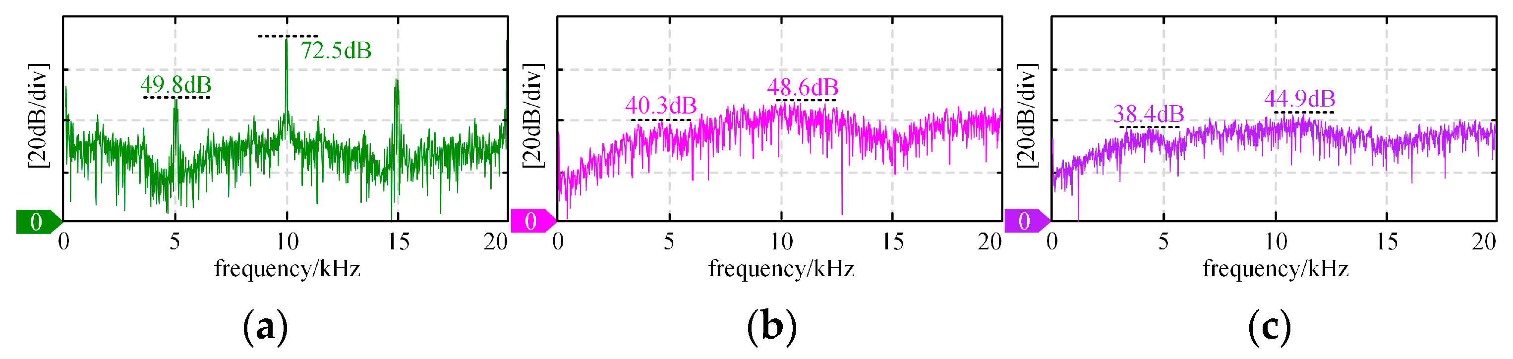
| Strategy I | 49.8 dB | 72.5 dB | 68.5 dB | 79.1 dB |
| Strategy II | 40.3 dB | 48.6 dB | 52.9 dB | 57.1 dB |
| Strategy III | 38.4 dB | 44.9 dB | 48.4 dB | 55.3 dB |
| Strategy | 300 rpm | 1200 rpm | ||
|---|---|---|---|---|
| 5 kHz | 10 kHz | 5 kHz | 10 kHz | |
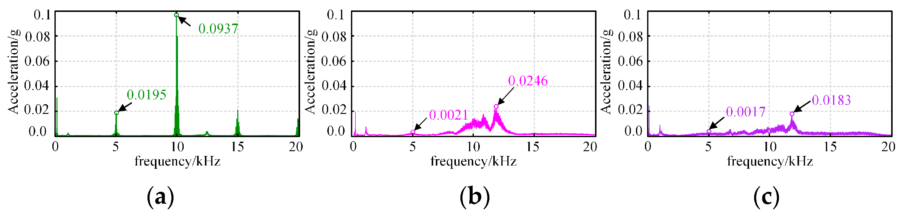
| Strategy I | 0.0195 g | 0.0937 g | 0.0425 g | 0.2190 g |
| Strategy II | 0.0021 g | 0.0246 g | 0.0039 g | 0.0458 g |
| Strategy III | 0.0017 g | 0.0183 g | 0.0031 g | 0.0373 g |
Disclaimer/Publisher’s Note: The statements, opinions and data contained in all publications are solely those of the individual author(s) and contributor(s) and not of MDPI and/or the editor(s). MDPI and/or the editor(s) disclaim responsibility for any injury to people or property resulting from any ideas, methods, instructions or products referred to in the content. |
© 2025 by the authors. Licensee MDPI, Basel, Switzerland. This article is an open access article distributed under the terms and conditions of the Creative Commons Attribution (CC BY) license (https://creativecommons.org/licenses/by/4.0/).
Share and Cite
Gu, X.; Wu, K.; Jin, X.; Zhang, G.; Chen, W.; Li, C. Dual-Random Space Vector Pulse Width Modulation Strategy Based on Optimized Beta Distribution. Electronics 2025, 14, 1779. https://doi.org/10.3390/electronics14091779
Gu X, Wu K, Jin X, Zhang G, Chen W, Li C. Dual-Random Space Vector Pulse Width Modulation Strategy Based on Optimized Beta Distribution. Electronics. 2025; 14(9):1779. https://doi.org/10.3390/electronics14091779
Chicago/Turabian StyleGu, Xin, Kunyang Wu, Xuefeng Jin, Guozheng Zhang, Wei Chen, and Chen Li. 2025. "Dual-Random Space Vector Pulse Width Modulation Strategy Based on Optimized Beta Distribution" Electronics 14, no. 9: 1779. https://doi.org/10.3390/electronics14091779
APA StyleGu, X., Wu, K., Jin, X., Zhang, G., Chen, W., & Li, C. (2025). Dual-Random Space Vector Pulse Width Modulation Strategy Based on Optimized Beta Distribution. Electronics, 14(9), 1779. https://doi.org/10.3390/electronics14091779