Article

Torque Ripple Reduction in Switched Reluctance Machines Considering Phase Torque-Generation Capability

1
School of Electrical Engineering, Southeast University, Nanjing 210096, China
2
Innovation Center for Control Actuators, AVIC Xi’an Flight Automatic Control Research Institute, Xi’an 710076, China
*
Author to whom correspondence should be addressed.
These authors contributed equally to this work.
Electronics 2025, 14(9), 1757; https://doi.org/10.3390/electronics14091757
Submission received: 26 March 2025 / Revised: 18 April 2025 / Accepted: 21 April 2025 / Published: 25 April 2025

Abstract

:
In this paper, an improved online torque compensation strategy considering phase torque-generation capability is proposed to enhance the conventional torque-sharing function (TSF), thus reducing torque ripple for switched reluctance machines (SRMs). The improvements are mainly attributed to two aspects: First, the phase turn-on angle and TSF starting angle are separated. Thus, the phase turn-on angle can be advanced independently to enhance the torque-generation capability of the incoming phase. Second, to generate the desired torque with minimum current, the torque per ampere (TPA) characteristic is considered for commutation region separation. This can ensure that in each separated region, the phase with a stronger torque-tracking ability is utilized for torque error compensation. Accordingly, efficiency is not sacrificed. In addition to improving the TSF, a direct instantaneous torque control (DITC) method combined with a PWM regulator is proposed to reduce large torque increments due to the limited control frequency. As a result, the torque ripple can be further suppressed. Finally, an experimental setup is established, and tests are conducted under different working conditions. The results demonstrate the effectiveness of the proposed method.

1. Introduction

Switched reluctance machines (SRMs) have garnered significant attention in recent years due to their low cost, robust structure, large starting torque, and wide speed range. Therefore, SRMs have been applied in electric vehicles [1], aircraft [2], home appliances [3], industrial applications [4], and other systems [5]. However, significant torque ripple issues limit their application in high-precision, noise-sensitive, and high-comfort scenarios such as robot joint control, medical equipment, and electric bicycles [1,6,7,8,9,10,11,12,13,14,15,16,17,18,19,20,21,22,23,24,25,26,27,28,29,30,31,32,33].
The existing methods for torque ripple reduction are mainly divided into two categories: machine structural optimization [1,10,11,12,13] and control algorithm design [14,15,16,17,18,19,20,21,22,23,24,25,26,27,28,29,30,31,32]. From the machine structural optimization aspect, in Ref. [10], the stator and rotor pole arcs are optimized for higher torque and reduced torque ripple. In Ref. [11], a notched tooth rotor is proposed to reduce the fringing flux prior to the overlap angle. Hence, the inductance waveform can be closer to the ideal waveform to reduce the ripple before the overlap angle. In Ref. [12], the rotor tooth and slot, as well as the phase current, are tuned simultaneously to eliminate both the current ripple and torque ripple. Recently, the double-stator SRM has gained attention due to its higher torque density and lower torque ripple [1,13]. The novel machine structures can effectively reduce torque ripple. However, for machines that have already been manufactured, improvements using control algorithms offer greater flexibility.
The block diagram of the common torque ripple suppression methods for switched reluctance motors (SRMs) is shown in Figure 1. The system mainly consists of a reference torque-generation module, a torque control module, etc. Among these, the torque-sharing function (TSF) is widely adopted in the reference torque-generation module due to its computational simplicity. In Ref. [14], a comprehensive comparison is made among linear, cubic, cosine, and exponential torque-sharing functions. In Ref. [15], a multi-objective TSF is proposed to optimize the torque ripple, copper loss, and speed range simultaneously. In Ref. [16], torque compensation based on a proportional–integral controller is applied to the phase with the higher absolute value of the flux change rate to extend the low-ripple speed range. In Ref. [17], considering the torque-generation capability of the adjacent two phases during commutation, the TSF is modified and compensated to reduce the ripple, namely the online compensated TSF (OCTSF). However, although the OCTSF adopted in the literature [17] separates the commutation regions based on the torque-generation capabilities of two phases, this separation method does not fully utilize the torque-generation potential of both phases. Consequently, the method suffers from insufficient torque-tracking capability, leading to significant torque ripple.
The torque control module has many different types of control algorithms. Direct torque control (DTC) [18,19,20,21,22] was initially proposed for AC machines and has been applied in SRMs in recent years. The optimal space voltage vector is selected based on the output of the flux and torque hysteresis controller. However, in DTC, the generation of negative torque is required to ensure total torque tracking of the reference value, which degrades the torque–current ratio and reduces motor efficiency [23]. To reduce the torque ripple caused by current ripples, advanced current controllers such as the fixed-frequency PWM regulator [24,25] are proposed. Recently, model predictive control (MPC) has garnered interest [22,26,27,28,29]. In Ref. [26], a novel MPC method is proposed to reduce torque ripple and source current ripple simultaneously when considering bus voltage fluctuations for three-phase SRMs. In Ref. [27], a novel model predictive torque-control method was proposed to reduce the torque ripple with low measurement effort, small storage space requirements, and low computation burden. In Ref. [22], a finite control set model predictive direct torque method was proposed to simultaneously reduce torque ripple and copper losses, while ensuring flux linkage tracking and minimizing switching frequency for segmented switched reluctance motors under low-speed operation. In Ref. [28], a flux linkage loop-based model predictive torque control method was proposed that utilizes the voltage vector selection logic of DTC and the flux linkage loop to assist in selecting candidate switch states, thereby reducing the number of switch state combinations requiring computation from 27 to 2 and significantly lowering the computational burden. However, despite optimizations in MPC, it still imposes a significant computational burden, which restricts its adoption in low-cost application scenarios [29]. Direct instantaneous torque control (DITC) [30,31,32,33] eliminates the flux hysteresis loop of direct torque control and takes the instantaneous torque as the control variable. Based on the difference between the actual torque and reference torque, corresponding commutation logic is obtained to ensure that the instantaneous torque can follow the reference torque accurately. However, the hysteresis bandwidth setting of DITC must balance the trade-off between torque ripple suppression effectiveness and the motor’s inherent control frequency constraints, making parameter optimization challenging [34].
In this paper, considering the phase torque-generation capability during different stages, an improved OCTST is proposed as the phase torque reference generation module. First, in contrast to conventional OCTSFs, the phase turn-on angle and the TSF starting angle are separated. Thus, the turn-on angle can be advanced flexibly to enhance the phase torque-generation capability at the early stage of excitation. Second, in contrast to conventional OCSTFs, the two regions during commutation are separated according to the TPA characteristic, realizing torque error compensation without sacrificing efficiency. Then, based on the generated phase torque reference and due to the limited control frequency, a PWM-integrated DITC method is proposed to reduce the torque increment. Consequently, the resulting torque is within the hysteresis band; thus, the torque ripple can be reduced.
The main contributions of this paper are as follows:
(1)
Decoupling the phase turn-on angle from the starting angle of the TSF enables flexible adjustment of the turn-on angle to enhance torque-generation capability, achieving an approximately 10% reduction in torque ripple.
(2)
During commutation intervals, torque errors are compensated by the phase with greater torque-tracking ability, as evaluated using TPA characteristics, resulting in a 26% reduction in torque ripple without sacrificing efficiency.
(3)
A PWM-integrated DITC method is proposed to address large torque increments caused by limited practical control frequencies, effectively constraining torque within the hysteresis band and achieving a 25% reduction in torque ripple.

2. Online Compensated Torque-Sharing Function

2.1. Origin of Torque Ripple

The generated torque of each phase is approximately calculated when saturation is neglected, as follows:
  T k = 1 2 i k 2 d L k i k , θ d θ
where θ is the rotor position; Tk and ik are the k-th phase torque and k-th phase current, respectively; Lk (ik,θ) is the inductance of the k-th phase as a function of current and rotor position; and k indicates the phase index. As shown in Figure 2, the variation in inductance with rotor position reveals the nonlinear nature of torque generation.
The typical current, inductance, and torque waveforms are shown in Figure 3. This figure shows that the torque ripple originates from two sources: current ripple and commutation. During the single-phase excitation period, the current will oscillate due to the PWM regulator or current chopping, resulting in torque ripple. During commutation, the outgoing phase is turned off, entering the demagnetization state, and the incoming phase is turned on to be magnetized. With the decreased current, the torque of the outgoing phase decreases rapidly. Although the current of the incoming phase increases quickly, the generated phase torque is minimal due to the small inductance slope. Hence, during commutation, the total torque is suddenly reduced compared with that during the single-phase excitation period.

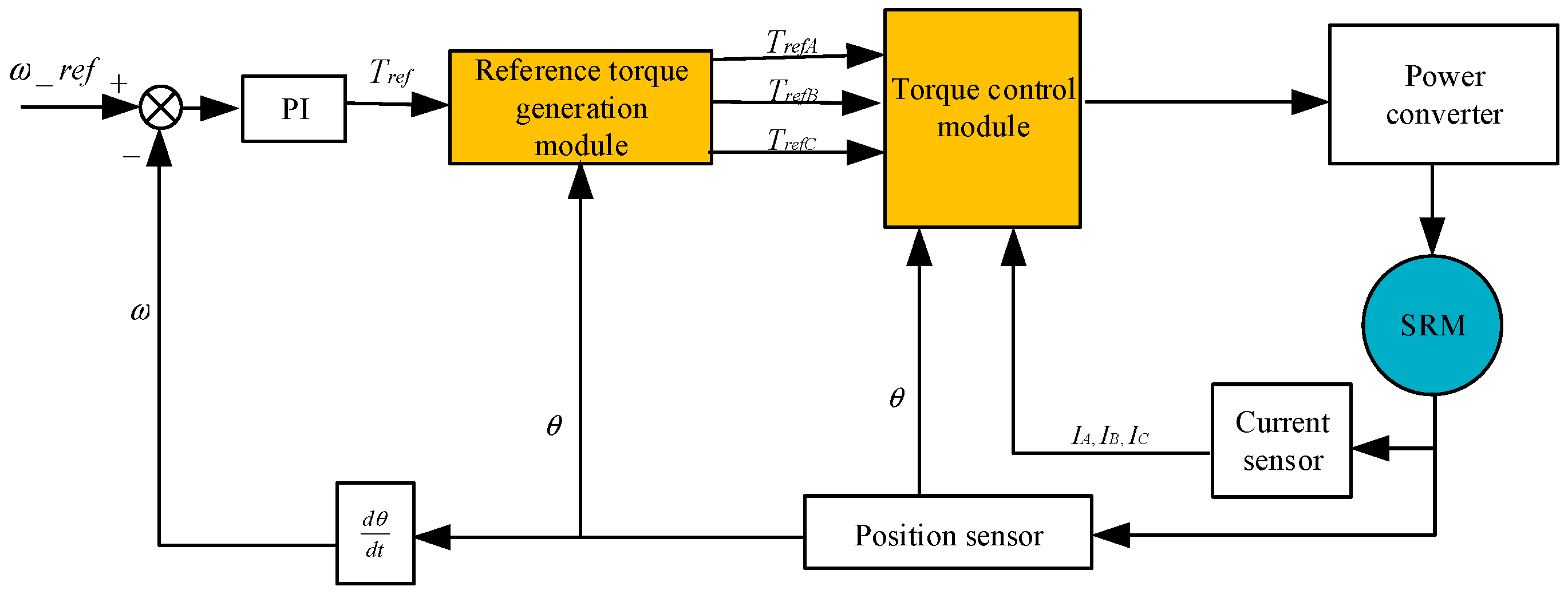
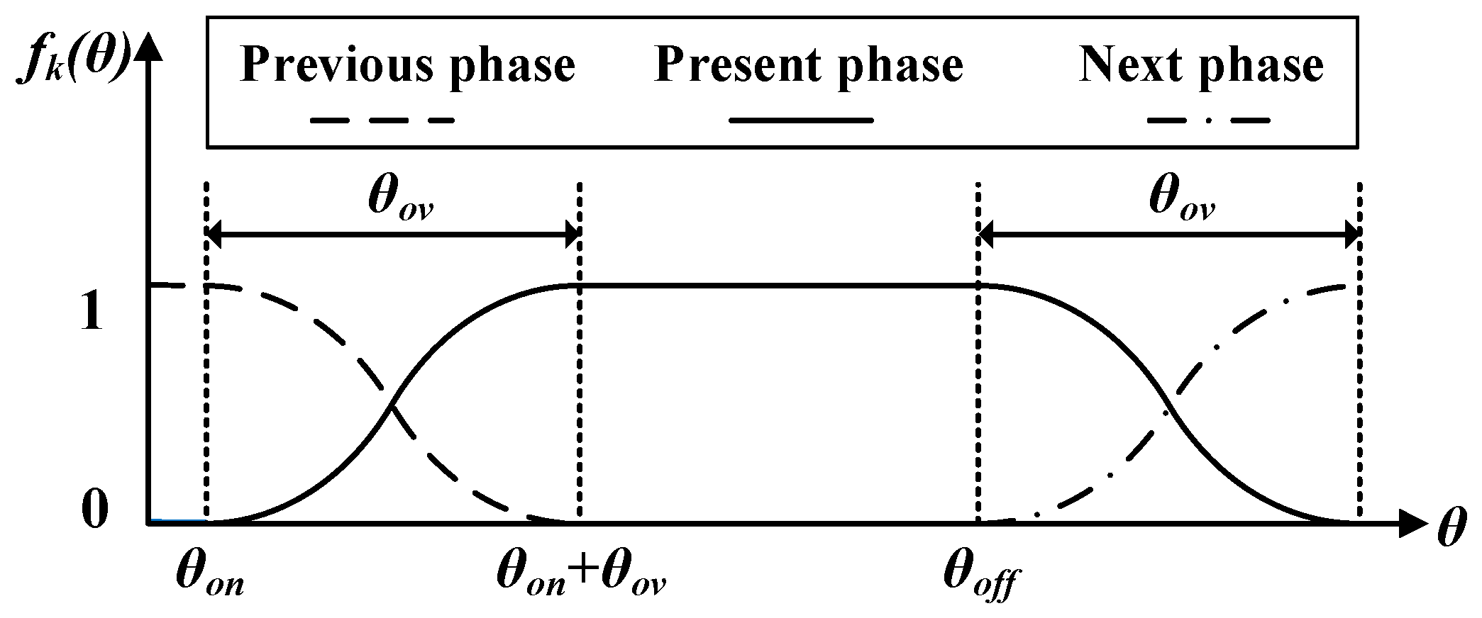
2.2. Conventional TSF

The design of the TSF aims to maintain a constant total torque. The basic concept is that, at any moment, only one phase or two adjacent phases are excited, and the sum of the TSF of each phase is equal to 1. The TSF is a function related to rotor position. Defining the TSF of the kth phase as fk(θ), accordingly, we obtain the following:
  k = 1 m f k θ = 1 , 0 f k θ 1
where m is the number of phases.
Then, assuming that the total reference torque is Tref_total, the reference torque of each phase can be obtained as follows:
  T k _ r e f θ = T r e f _ t o t a l · f k θ
The TSF usually has linear, cosine, cubic, and exponential types. In Ref. [14], the four types are compared in terms of the effective rate-of-change of flux linkage (ERCFL) and copper loss. The exponential type has the smallest ERCFL, so it has the widest speed range. However, the variation in angle parameters has a great impact on its performance. Linear TSF has the largest ERCFL, so its performance is the worst. The cosine and cubic types have similar ERCFL values and will not be affected by the variation in angle parameters. In terms of copper loss, the cosine type is relatively small. Hence, the cosine-type TSF exhibits better overall performance. The conventional cosine-type TSF is shown in Figure 4, where θon and θoff are the turn-on and turn-off angles, respectively, and θov is the overlapping width of the adjacent two phases during commutation.
Then, the electrical period can be divided into four stages:
(1)
θon < θ < θon + θov: The present phase and the previous phase overlap. Here, the reference torque of the present phase increases, while the reference torque of the previous phase decreases.
(2)
θon + θov < θ < θoff: The reference torque of the previous phase has returned to zero. Only the present phase is excited, to provide the total torque.
(3)
θoff < θ < θoff + θov: The present phase and the next phase overlap. Here, the reference torque of the present phase decreases, while the reference torque of the next phase increases;
(4)
Others: The present phase is turned off, and the reference torque is zero.
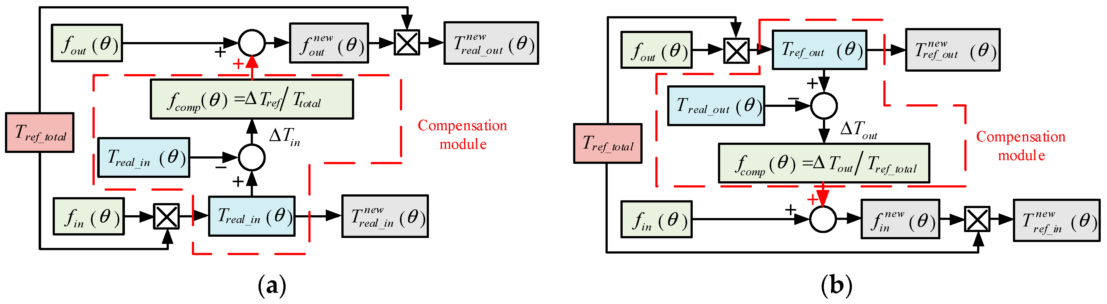
Ideally, the conventional TSF can ensure that the sum of each phase torque is constant. However, it ignores the practical phase torque-generation capability during commutation. In Figure 5, the commutation region is divided into two regions. The TSF rising phase is defined as the incoming phase, and the TSF falling phase is defined as the outgoing phase.
For Region I, the present phase is newly magnetized. It is the incoming phase and lies within the minimum inductance region. According to (1), the torque-generation capability is very weak. Hence, to improve the torque-generation capability, a larger current should be injected. However, in real practice, the maximum current is limited by the power converter. Eventually, errors will occur between the reference phase torque and the actual phase torque.
For Region II, the present phase is demagnetized, which turns out to be the outgoing phase. Even though it is fully under the demagnetization state, the actual torque of the outgoing phase is usually larger than the reference value, causing a negative error between the reference and the actual phase torque.
Based on the analysis above, although the conventional TSF can suppress the torque ripple to some extent, by neglecting the phase torque-generation capability, there is still potential for decreasing the torque ripple.

2.3. OCTSF

Recently, the OCTSF has been proposed in [17], as shown in Figure 6. The core concept is that the phase with the greater torque-tracking ability is selected for torque error compensation.
In Region I, the torque-generation capability of the incoming phase is weaker than that of the outgoing phase due to the small inductance slope. Hence, the error between the actual and reference torque of the incoming phase can be compensated by the outgoing phase. Similarly, in Region II, the incoming phase is selected as the compensation phase. Accordingly, the torque error caused by the outgoing phase is compensated by the incoming phase. Note that, in Region II, the actual torque is always larger than the reference, even if the outgoing phase is completely in the demagnetization state, i.e., the error caused by the outgoing phase is negative. Hence, the compensated reference torque of the incoming phase is smaller than the uncompensated reference torque.
According to Reference [17], the realization of the OCTSF is illustrated in Figure 7. In Region I, the torque error caused by the incoming phase ΔTin is expressed as follows:
Δ T i n θ = T r e f _ i n θ T r e a l _ i n θ
where Tref_in is the reference torque of the incoming phase, and Treal_in is the actual torque of the incoming phase.
Then, the error caused by the incoming phase is converted to the TSF compensation value of the outgoing phase f c o m p :
f c o m p θ = Δ T i n / T r e f _ t o t a l
where Tref_total is the total reference torque.
Accordingly, the new TSF of the outgoing phase after compensation f o u t n e w is obtained:
f o u t n e w θ = f o u t θ + f c o m p θ
where fout is the TSF of the outgoing phase.
The corresponding reference torque of the outgoing phase is updated as follows:
T r e f _ o u t n e w θ = T r e f _ t o t a l · f o u t n e w θ
The reference torque of the incoming phase remains unchanged:
  T r e f _ i n n e w θ = T r e f _ i n θ = T r e f _ t o t a l · f i n θ
Similarly, in Region II, the torque error caused by the outgoing phase ΔTout is expressed as follows:
Δ T o u t θ = T r e f _ o u t θ T r e a l _ o u t θ
where Tref_out is the reference torque of the outgoing phase, and Treal_out is the actual torque of the outgoing phase.
Then, the error caused by the outgoing phase is converted to the TSF compensation value of the incoming phase as follows:
f c o m p θ = Δ T o u t / T r e f _ t o t a l
Accordingly, the new TSF of the incoming phase after compensation is calculated as follows:
    f i n n e w θ = f i n θ + f c o m p θ
where fin is the TSF of the incoming phase.
The corresponding reference torque of the incoming phase is updated as follows:
T r e f _ i n n e w θ = T r e f _ t o t a l · f i n n e w θ
The reference torque of the outgoing phase remains unchanged:
T r e f _ o u t n e w θ = T r e f _ o u t θ = T r e f _ t o t a l · f o u t θ

3. Improved OCTSF Considering the Phase Torque-Generation Capability

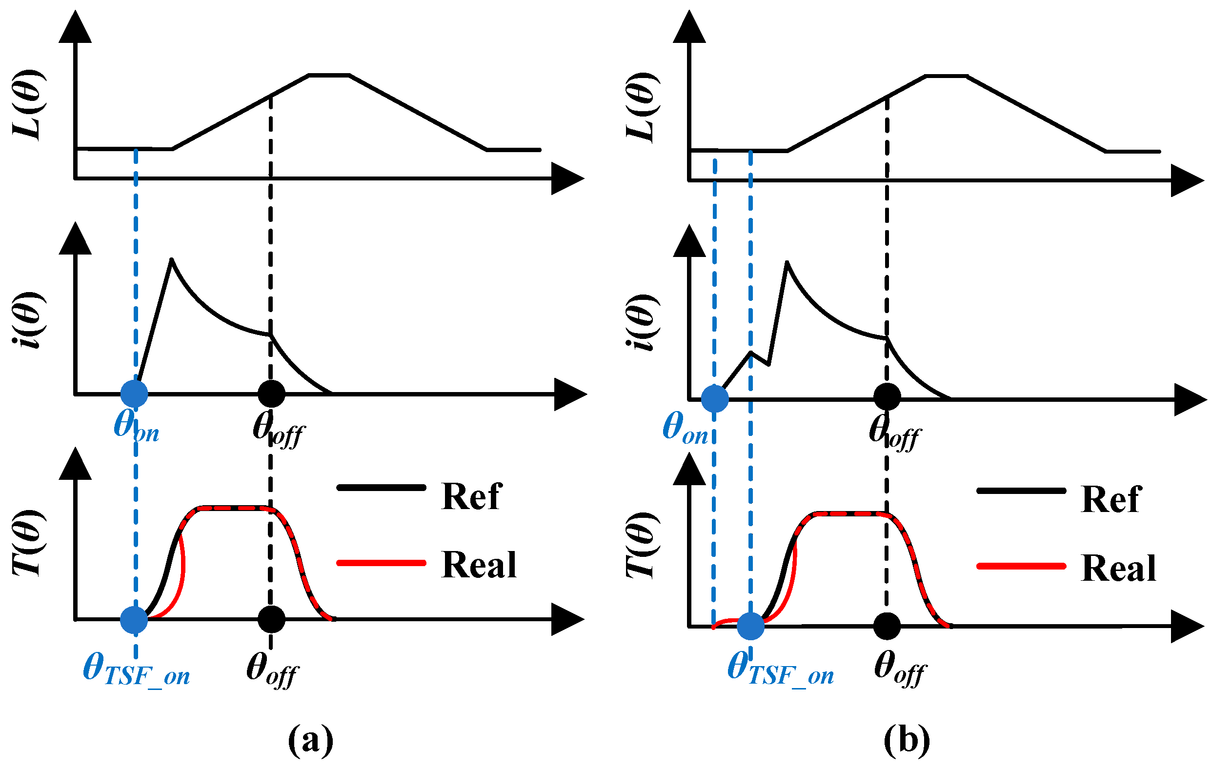
3.1. Turn-On Angle Advancement

Defining the TSF starting angle as θTSF_on and the phase turn-on angle as θon, the conventional and improved OCTSFs are compared in Figure 8.
In the conventional OCTSF, as shown in Figure 8a, θTSF_on and θon are always the same. When θon is less than 0°, the phase is within its inductance-decreasing region, so the phase torque is negative. However, the TSF can only give a positive value; hence, θon is limited to be no less than 0°. Accordingly, it is difficult to increase the phase current to generate the desired torque.
In the improved OCTSF, as shown in Figure 8b, θTSF_on and θon are set separately. To establish the current in advance, θon should be ahead of θTSF_on, i.e., the phase should be excited before the TSF begins. In Figure 8b, the phase is excited at θon, where the phase current starts to increase. At this time, the reference torque has not been distributed. Hence, the current within [θon, θTSF_on] continues to increase. Due to the small inductance slope at this time, the generated torque is very small, so it does not have a significant impact on the total torque. When the rotor reaches θTSF_on, the phase current has increased. Compared to a conventional OCTSF, the torque-generation capability is stronger due to the increased current at θTSF_on; thus, the error between the actual torque and the reference torque is also reduced. This is beneficial for reducing torque ripple.
To verify the effectiveness of the turn-on angle advancement, the simulation results between θon values of 0° and −3.5° are compared. From Figure 9a, because θon is 0°, no negative torque occurs during excitation. However, an obvious error occurs between the reference and actual torque as the current rises. In contrast, when θon equals −3.5°, as shown in Figure 9b, the actual torque can completely match the reference torque due to the improved torque-tracking ability with the increased current.
Because the torque before 0° is negative, it may influence the average torque and efficiency. Therefore, the performances with different θon values need to be investigated, and these are compared in Figure 10. As θon increases, the torque error is reduced; however, the negative torque is increased. This results in reduced efficiency. Hence, θon is not set as early as possible. Here, the criteria for selecting the turn-on angle is that the absolute value of negative torque should not exceed 0.1 Nm. Therefore, θon is selected as –1.5° in this paper.

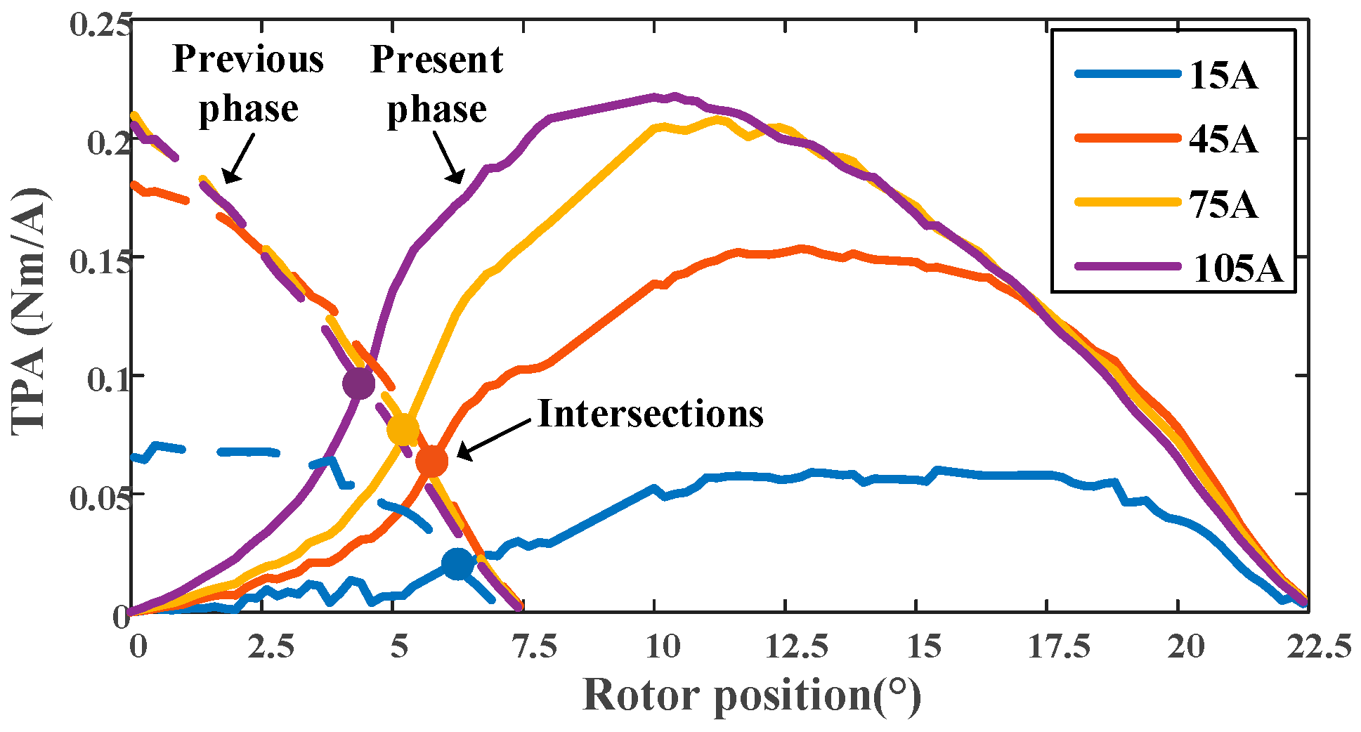
3.2. TPA-Based Commutation Separation

The same problem also occurs at the separation point, namely the intersection of Regions I and II. Specifically, it is unclear which position is the optimal separation point. Before this position, the torque-generation capability of the outgoing phase is stronger than that of the incoming phase. After this position, the torque-generation capability of the incoming phase is more flexibly tuned. Here, the torque-generation capability is evaluated based on the torque per ampere (TPA) characteristics as follows:
T P A = T k / i k
When TPA is considered, the desired torque can be generated at the lowest cost, i.e., using the minimum current. Hence, the phase currents are different, and both current values vary with rotor position. The TPA characteristics of the prototyped machine are shown in Figure 11. This figure shows that with the increase in phase current, the intersection of the TPA curves of the previous phase and the present phase will shift. That is to say, the optimal separation point will change with working conditions.
Accordingly, simulations under various working conditions are conducted to investigate the intersection position of adjacent two-phase TPA curves, as shown in Figure 10. The simulations are performed under the same load torque of 4 Nm. The phase current is tuned by changing θon. From Figure 12, two conclusions can be obtained:
(1)
At the same speed, as θon advances, the separation point also advances. However, the variation range is very narrow and within [4.5°, 5.3°].
(2)
When θon is fixed, with the increase in speed, the current-decreasing rate of the outgoing phase is faster, and the current-increasing rate of the incoming phase is slower, resulting in a slight increase in the separation point. However, the variation is smaller than 0.4° from 300 rpm to 1500 rpm.
Based on the above analysis, the variation range of the separation point is confined within [4.5°, 5.3°], representing a remarkably narrow interval. Within this range, the TPA characteristics of adjacent phases can be considered approximately equivalent. Any separation point selected from this interval is viable. This paper adopts the median value of 4.9° as the designated separation point. Although this specific value does not represent the optimal solution for all operational conditions, the selection of any point within this interval yields negligible impacts on system torque ripple. Moreover, employing a fixed separation point eliminates the requirement for real-time computation or pre-stored look-up tables, while maintaining acceptable compensation effectiveness.

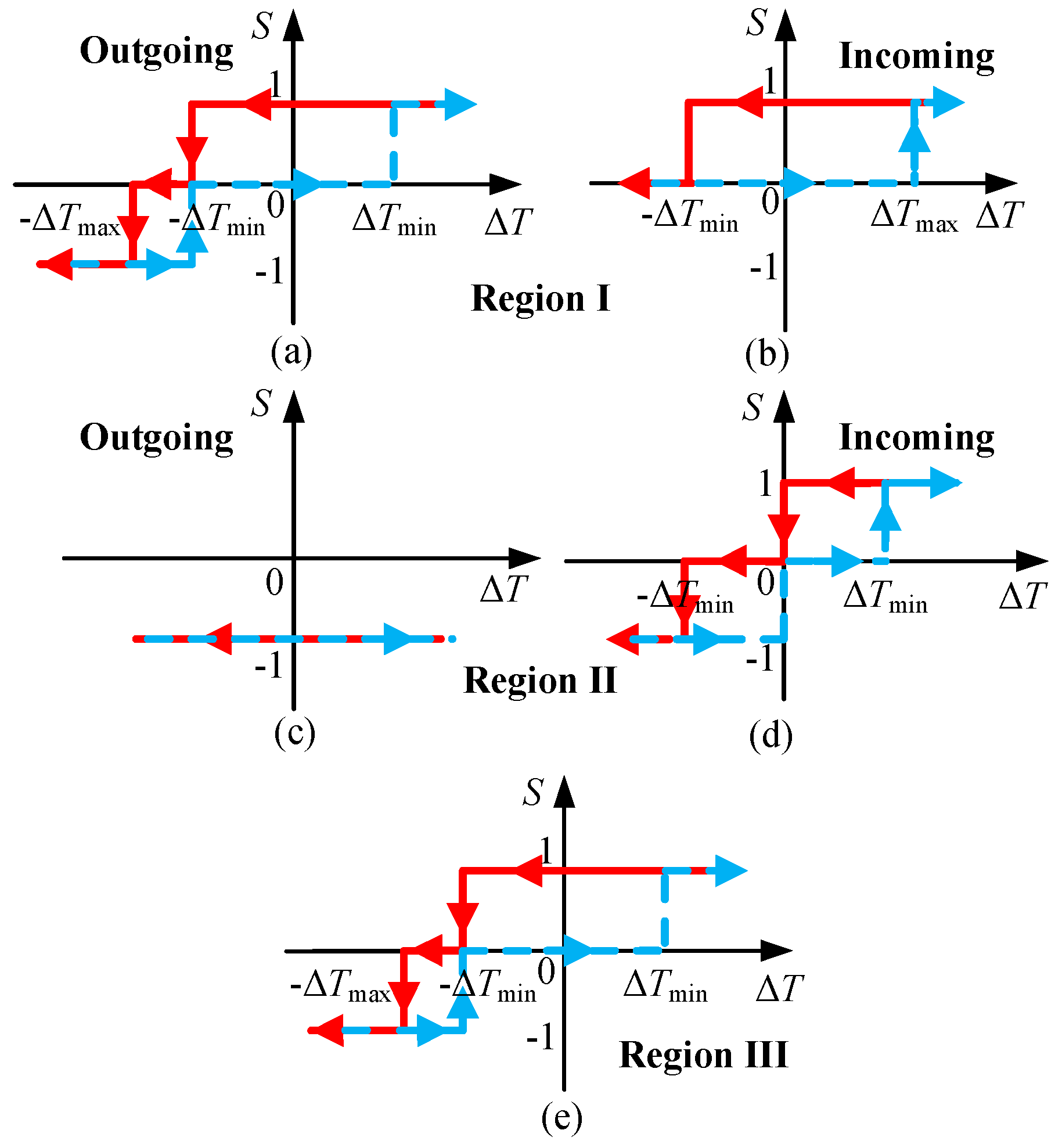
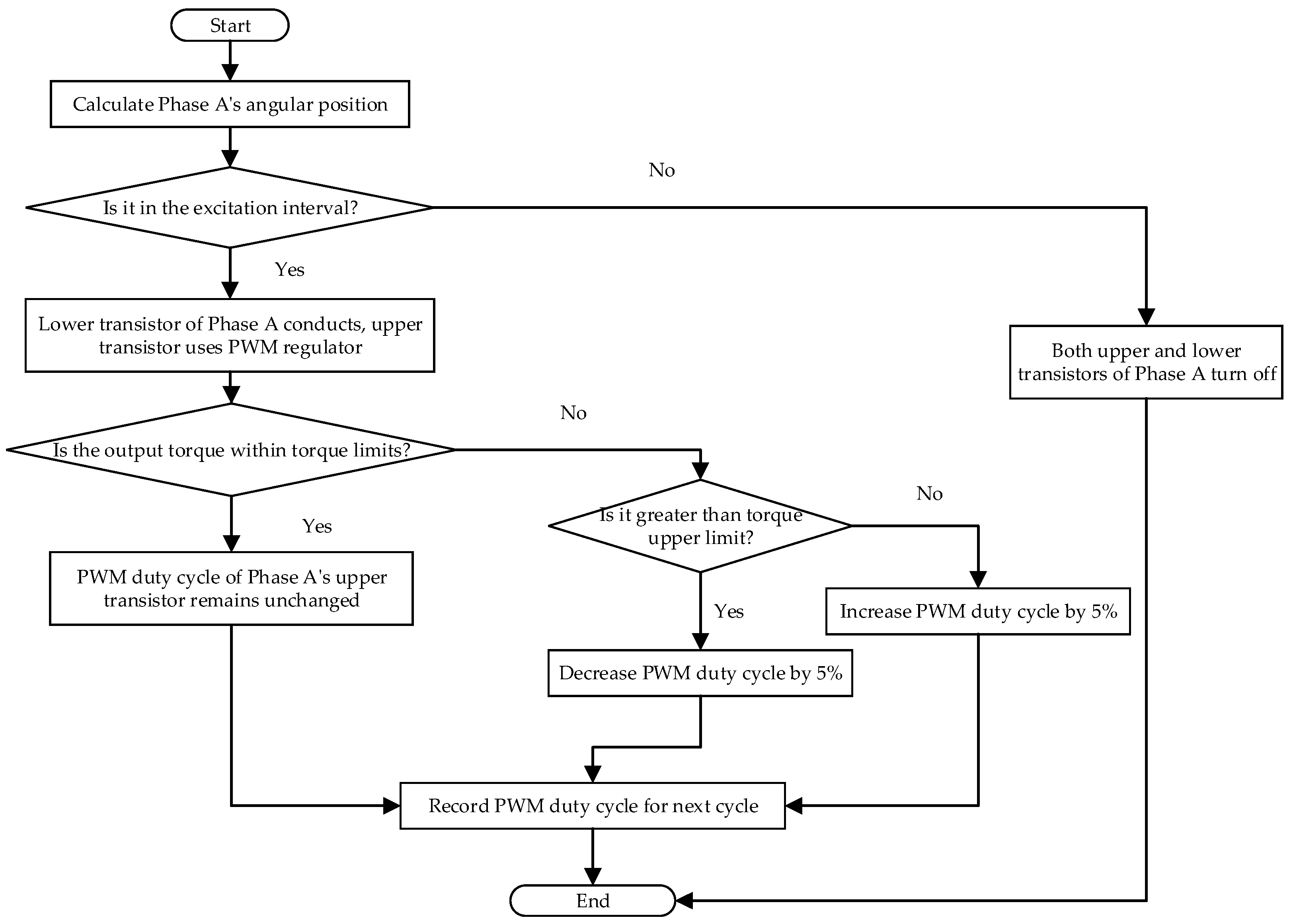
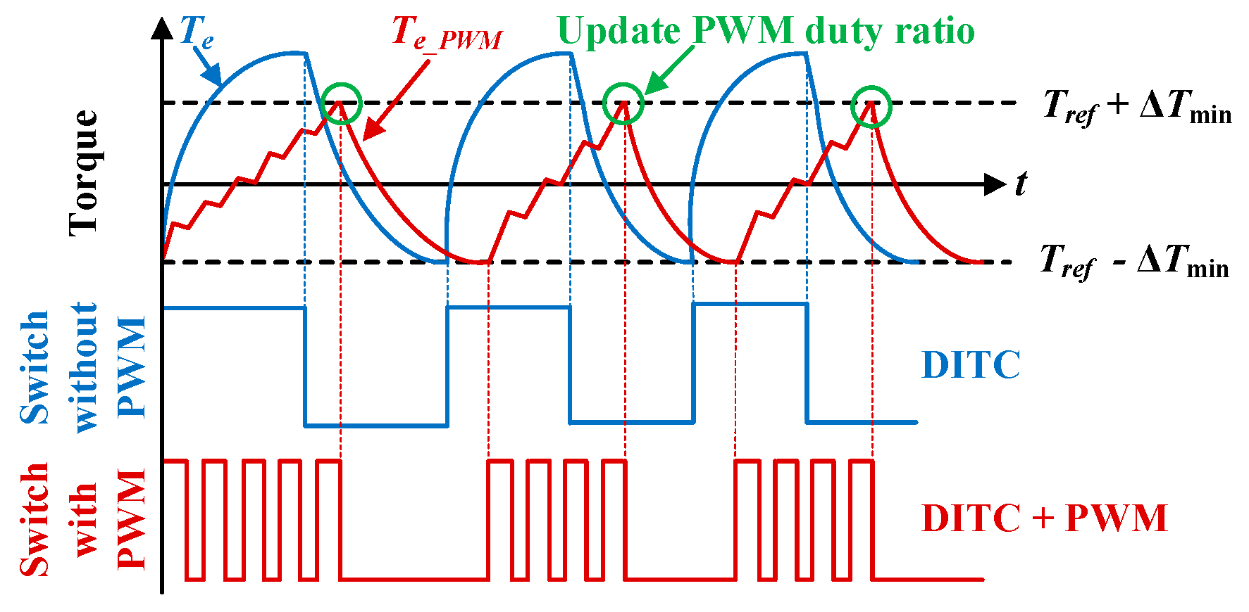
4. DITC Combined with a PWM Regulator

4.1. DITC

Based on the distributed OCTSF, the actual torque is regulated by the torque hysteresis rules, namely the direct instantaneous torque control. The hysteresis rules adopted here for different phases in different regions are shown in Figure 13.
In Region I, the outgoing phase is the dominant phase for torque control due to its stronger torque-generation capability. Therefore, the outgoing phase has three states that can control the torque flexibly, while the incoming phase does not have a demagnetization state. In Region I, the incoming phase must establish the current quickly to enhance its torque-generation capability for the follow-up regions.
In Region II, to avoid phase current freewheeling into the inductance-decreasing region and generating negative torque, the outgoing phase should always be demagnetized to reduce the current as fast as possible. The incoming phase is responsible for tracking the total torque, so it can operate in all three possible states.
In Region III, only one phase is excited. Hence, all three possible states are utilized to control the total torque.

4.2. Torque Change Rate Considering the Control Frequency

Torque hysteresis control achieves precise torque control by limiting the torque error within the hysteresis band. If the control frequency is sufficiently high, when the torque error reaches the upper or lower limit of the hysteresis loop, the controller can respond quickly and change the state of the power switches. Consequently, the torque can be accurately controlled within the hysteresis band, and the torque ripple is small as shown in Figure 14a. However, in real practice, the control frequency is often limited. Therefore, the control period becomes long, and a large torque increment may occur. Consequently, the actual torque may exceed the hysteresis band. That is to say, at a low control frequency, the small hysteresis band will lose efficacy, as shown in Figure 14b. Here, torque hysteresis control is executed through an interrupt with an interval of 25 us.
According to (1), the phase torque is related to both the inductance slope and current. The inductance slope, phase current, and torque increment waveforms are shown in Figure 15. Note that the torque increment waveform means the torque increases within the actual control period of 25 μs at different rotor positions. Before 4°, the generated torque is very limited, resulting in a small torque increase. This is due to the small phase inductance slope, even for a large phase current. When the rotor position is within [4°, 7°], the inductance slope increases rapidly. Hence, at low speeds, the rapid increase in current will lead to a sharp increase in torque. After 7°, the inductance slope continues to exhibit a large value, so the torque depends more on the phase current. Meanwhile, due to the increased torque-generation capability, the phase current is reduced. Hence, the torque increment is decreased after 7°. As shown in Figure 15c, the maximum torque increment within a control period between 5° and 7° can reach 1 Nm. Hence, a small hysteresis band smaller than 1 Nm will not have any effect.

4.3. PWM Regulator

The torque is related to the current and inductance slope. However, the inductance is an inherent characteristic that cannot be changed when the machine has already been manufactured. Therefore, the torque change rate can only be indirectly decreased by reducing the current change rate. Based on the phase voltage equation when neglecting the phase resistance, the following is obtained:
  U k = L k d i k d t + i k ω r d L k d θ
where ωr is rotational speed. Rewriting this equation in standard linear ordinary differential equation (ODE) form, the following is obtained:
d i k d t + ω r L k d L k d θ i k =   U k L k
The integrating factor is given as follows:
    μ t = e p d t = e ω r d L k d θ L k t
Multiplying both sides of Equation (16) by the integrating factor μ(t) and integrating it, we obtain the general solution:
i k t = C 0 e ω r d L k d θ L k t + U k ω r d L k d θ
where C0 is the initial state, which is a constant. Applying the initial condition ik(t0), the following is obtained:
i k t 0 = C 0 e ω r d L k d θ L k t 0 + U k ω r d L k d θ
This can be expressed as follows:
C 0 = i t 0 U k ω r d L k d θ e ω r d L k d θ L k t 0
Using ΔT to represent the control period and then substituting t0 and t0 + ΔT into Equation (19), the phase current values of adjacent periods can be calculated, and the current increment can be obtained as follows:
i k t 0 = i k t 0 + T i k t 0
Based on Equations (19) and (21), the current increment yields the following:
Δ i k Δ t = i t 0 U k ω r d L k d θ e ω r d L k d θ L k T 1 1 Δ T
When ΔT approaches 0 at infinity, Equation (19) can be expressed as follows:
Δ i k Δ θ = U k i t 0 ω r d L k d θ ω r L k
Equation (23) shows that the current change rate is related to phase voltage, phase inductance and its slope, and rotational speed. The inductance is the inherent characteristic of an already-manufactured machine. Under certain working conditions, the rotational speed is also fixed. Therefore, the current change rate can only be adjusted by the average phase voltage, which can be easily realized through PWM control. The flowchart of the PWM adjustment algorithm is shown in Figure 16.
The diagram of the proposed DITC combined with the PWM regulator is shown in Figure 16. When the torque increases or decreases to the boundary limit of the hysteresis band, the controller will first give a switching signal according to the hysteresis rules. Then, the PWM duty cycle will be updated based on the torque increment at the end of each PWM period. If the actual torque exceeds the upper threshold, the PWM duty cycle in the subsequent control period is triggered to decrease; conversely, if the torque falls below the lower limit, the duty cycle is modulated upward. A fixed adjustment step size is implemented for each control cycle. Using the method of exhaustive duty cycle optimization, it was found that a 5% adjustment step size achieved the optimal torque ripple suppression effect. Thus, this step size was selected as the system adjustment parameter. In Figure 17, Te and Te_PWM are the torque waveforms before and after using PWM control. Although the proposed method increases the switching frequency of the upper switch, it can effectively reduce the increasing current rate and thus the torque change rate, resulting in a smoother torque. Therefore, the torque ripple caused by the limited control frequency can be effectively mitigated.
Although the introduction of PWM control inevitably increases switching losses, the torque compensation strategy based on the TPA described in Section 3 effectively improves current utilization and reduces overall losses. As a result, the overall system efficiency is enhanced. This conclusion is further validated by the experimental results presented in the following sections.

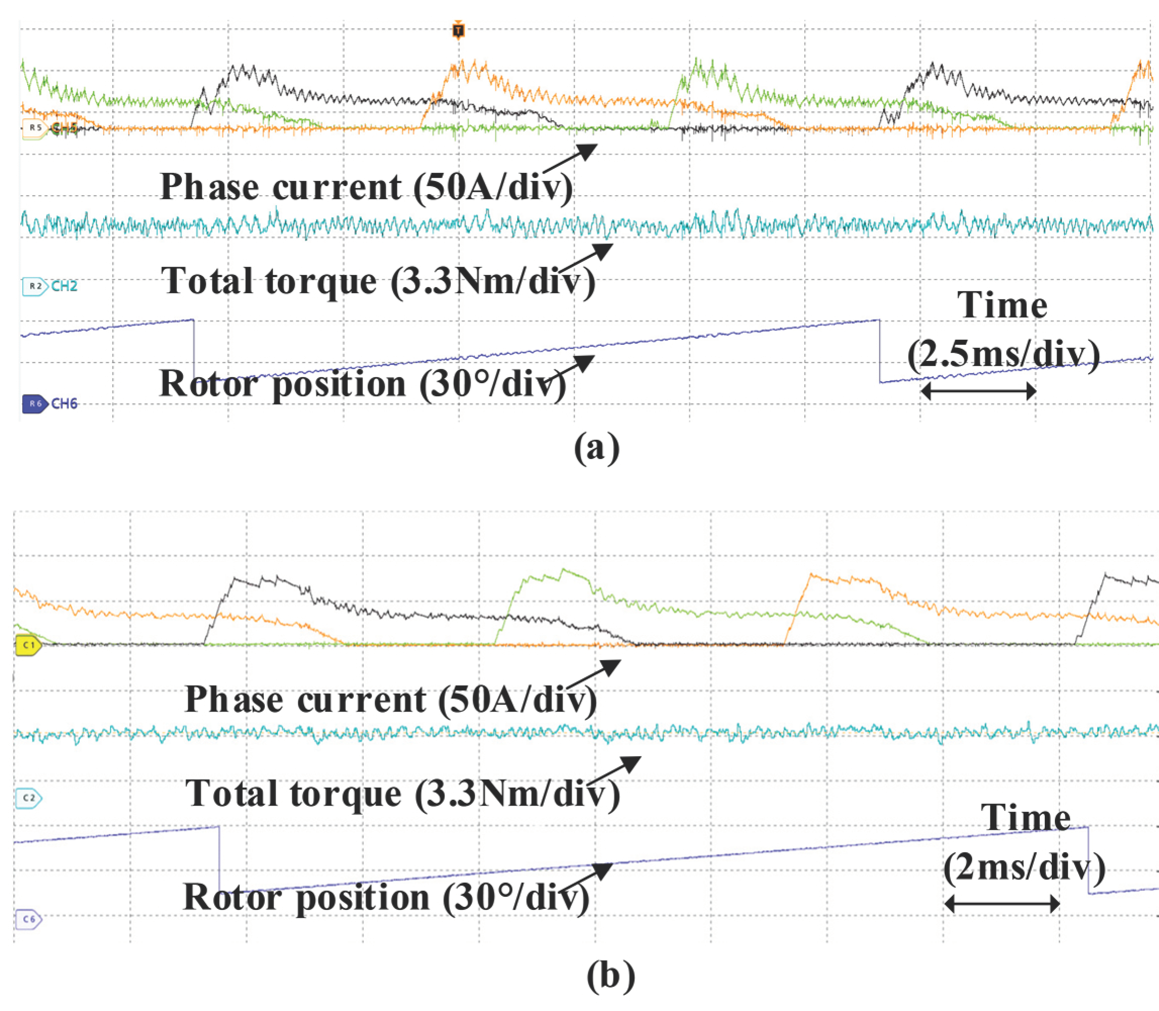
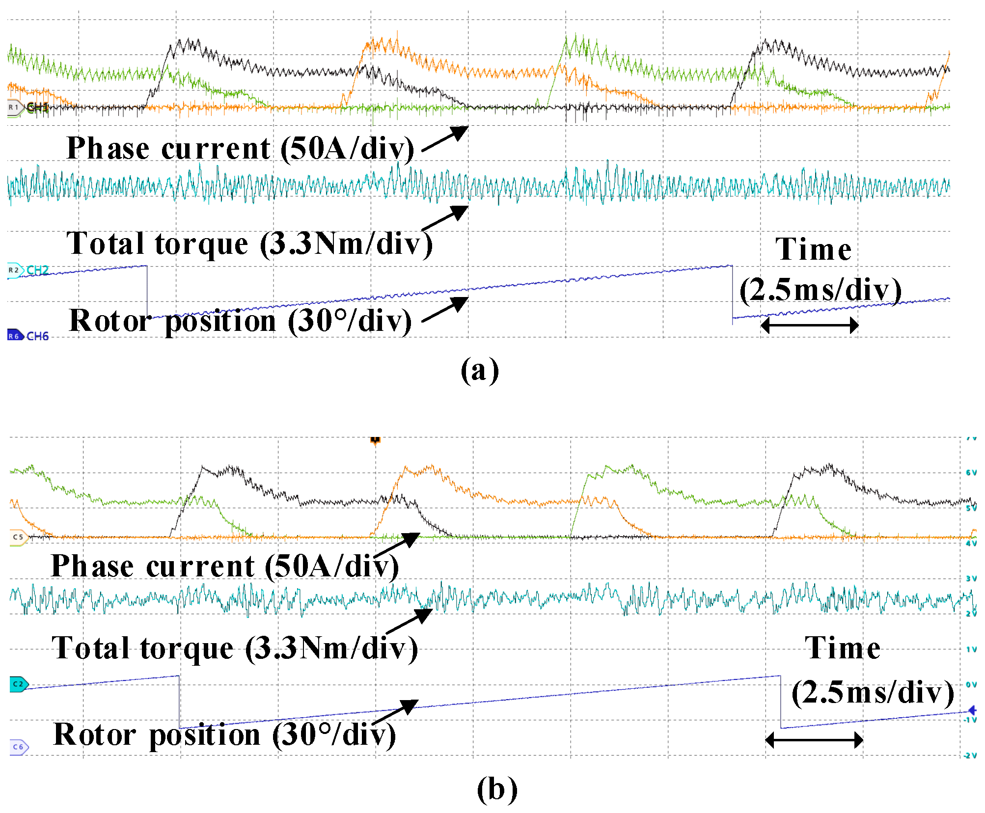
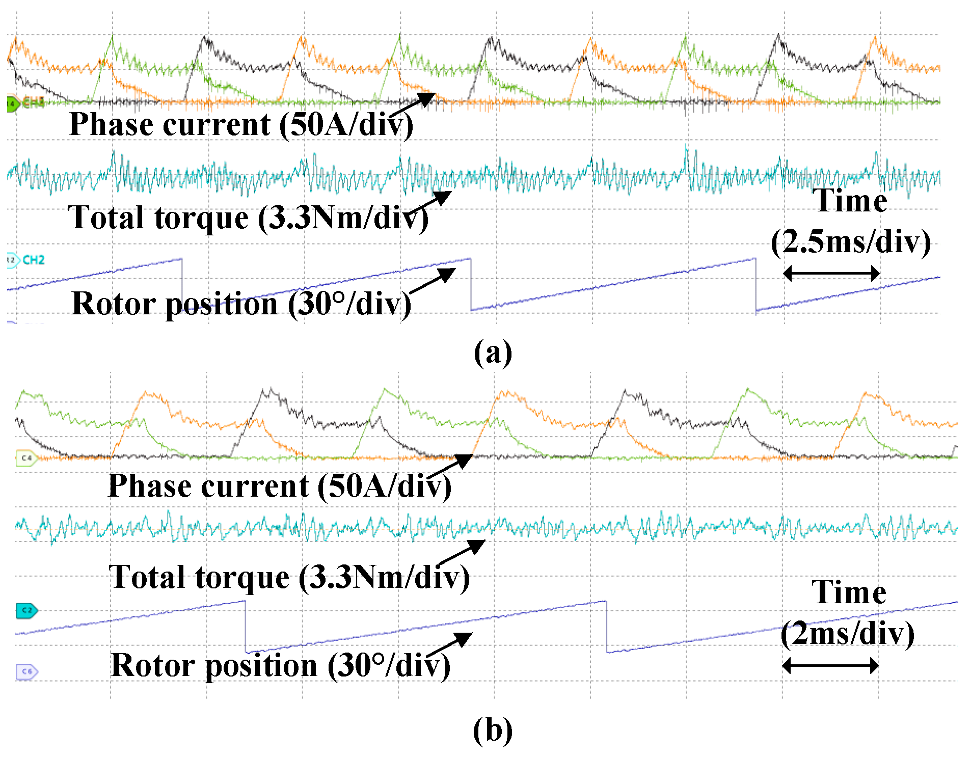
5. Experimental Verification

To validate the proposed methodology, a switched reluctance motor test platform was constructed in this paper, and the prototype parameters are detailed in Table 1.
The experimental setup is displayed in Figure 18 and mainly consists of a prototyped 12/8 SRM, DC power supply, a self-made STM32F405RGT6-based controller, torquemeter, dynamometer, current Hall sensors, magnetic powder brake, and oscilloscope. The DC power supply provides real-time monitoring of input current and voltage, enabling the direct calculation of input power based on the product of these two electrical parameters. Simultaneously, the dynamometer measures both mechanical output torque in Newton-meters and rotational speed in revolutions per minute, with the output power derived from the multiplication of torque and speed values. System efficiency is subsequently determined by comparing the output mechanical power against the input electrical power and expressed as a percentage ratio reflecting energy conversion effectiveness.
The effectiveness of the proposed method is verified under various working conditions. In experiments, both the control period and sampling period are set to 25 μs, with the PWM resolution configured at 10 bits. The TPA-based commutation separation point is set to 4.9°, and the PWM adjustment value is ±5%. In conventional OCTSFs, the θon and θTSF_on are consistent, and both are 0°. In the improved method, the advanced turn-on angle θon is −1.5°, and θTSF_on is 0°. For both the conventional and improved methods, the turn-off angle θoff is set as 15°, and the overlap angle θov is set as 7.5°. The inner and outer bands of the hysteresis rules are 0.25 Nm and 0.35 Nm, respectively.
The results of the conventional and improved method at 500 rpm under 4 Nm are compared in Figure 19. When the speed is low and the load is light, the current change rate is fast, so the torque changes rapidly. Therefore, during commutation, both the outgoing and incoming phases can effectively track the reference torque. However, at the end of the commutation and within the single-phase conduction region, the torque change rate is too fast, and the controller is unable to respond to the rapid torque change in a timely manner. Thus, the torque will far exceed the upper limit of the hysteresis band, resulting in a large torque pulsation. For the improved method, PWM control is used to reduce the current change rate, thereby reducing the torque change rate. The torque ripples of the traditional and improved methods are 72.3% and 35.6%, respectively, representing a 36.7% reduction.
When the load increases from 4 Nm to 8 Nm at 500 rpm, the incoming phase during commutation requires a larger current to produce the required torque, as shown in Figure 20. In the late stage of commutation and the single-phase conduction region, the larger current will produce a larger torque. Compared to light load conditions at the same speed in Figure 20, the torque ripple is more severe. For a 4 Nm load, the torque ripple of the conventional OCTSF method reaches 69.3%, while the proposed method reduces it to 35.6%, achieving a torque fluctuation suppression rate of 48.6%. For an 8 Nm load, the torque ripple decreases from 63.4% with the conventional method to 31.2% using the proposed method, resulting in a suppression rate of 50.8%. This finding demonstrates that with the increased load, the improved method still exhibits better torque ripple performance than the traditional method.
The experimental comparison results at 1000 rpm under 4 Nm and 8 Nm loads are shown in Figure 21 and Figure 22, respectively. As the speed increases, the phenomenon is almost the same as that noted at 500 rpm. The torque ripple is only minimally increased and can be considered almost the same as that noted at 500 rpm. For a 4 Nm load, the torque ripple of the conventional OCTSF method is 70.3%, while the proposed method reduces the torque ripple to 38.7%, achieving a torque fluctuation suppression rate of 45%. For an 8 Nm load, the torque ripple decreases from 67.8% to 33.6%, resulting in a suppression rate of 50.4%.
Comparing 500 and 1000 rpm across both loads highlights that the torque ripple of the proposed method decreases only modestly with speed; however, it remains substantially lower than that noted with the conventional approach in all cases. This demonstrates the robustness of the improved method against both load and speed variations. However, with a further increase in speed, the rotational back electromotive force will take effect, influencing the current change rate and thus the torque change rate. The high-speed torque ripple condition requires further discussion and alternative reduction strategies.
Table 2 shows that the efficiencies of the improved method under different working conditions is comparable to, or even higher than, the conventional method. Hence, the proposed method not only reduces torque ripple but also maintains or even enhances efficiency. The improvement in efficiency primarily stems from the TPA-based separation strategy. Although advancing the turn-on angle causes phase currents to be established earlier, increasing copper losses, and the PWM modulator introduces additional switching losses and iron losses, the TPA-based separation strategy enhances system efficiency by selecting phases with stronger torque-generating capabilities for torque production, thereby improving current utilization. This approach not only compensates for the efficiency losses caused by the advanced turn-on angle and PWM modulation but can also achieve an overall improvement in efficiency under certain operating conditions.
In addition, temperature effects cannot be neglected. As temperature increases, the winding resistance increases, and the magnetic permeability decreases, both of which adversely impact flux linkage and ultimately degrade torque performance. At 500 rpm and 4 Nm, the torque ripple of the conventional TSF and the proposed method at different temperatures is compared, as shown in Figure 23. Despite a slight decrease in torque ripple suppression with increasing temperatures, the proposed method consistently maintains lower torque ripple levels, indicating that it remains effective under varying temperature conditions.

6. Conclusions

In this paper, based on a conventional OCTSF, three steps are taken to further reduce the tracking error between the reference and actual phase torque considering the torque-generation capability of different phases in different regions: (1) advancing the turn-on angle to allow the phase current to build up rapidly before commutation, thus generating torque earlier; (2) applying TPA-based commutation region separation, thus enabling phases with stronger torque-generation ability to provide compensation and better track the reference torque; and (3) integrating the PWM regulator with the DITC method to constrain the output torque within a limited range, thereby reducing torque ripple. Experimental results show that the proposed method reduces the torque ripple by more than 30% compared with the conventional OCTSF method. In addition, the efficiency is not sacrificed. These findings fully demonstrate the feasibility and effectiveness of the proposed method.
However, there are several aspects that require further investigation:
(1)
Although the proposed method has only been validated for the 12/8 topology, it is theoretically applicable to machines with two or more phases. Further studies are needed to verify its generalization to other topologies.
(2)
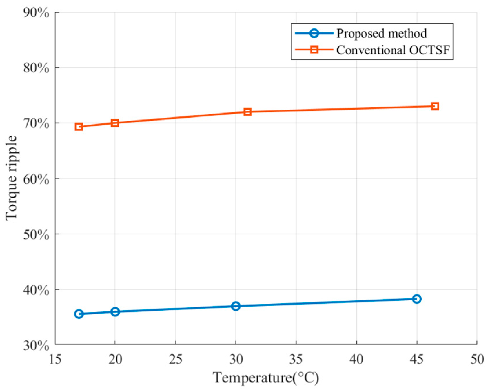
The method has demonstrated good performance at speeds below 1500 rpm, and it has shown excellent torque ripple suppression performance across a load range from half the rated torque to three times the rated torque. To expand its applicability, further research is required to assess its effectiveness at higher speeds.
(3)
In this paper, the separation point is treated as a constant. To enhance accuracy under varying operating conditions, future work could investigate the use of adaptive or predictive methods to dynamically optimize this value.
(4)
This study primarily focused on error compensation for optimizing TSF. Future research could explore the application of techniques such as genetic algorithms or neural networks to achieve more refined TSF optimization.

Author Contributions

Methodology, validation, and writing, S.C.; conceptualization and original draft preparation, X.G.; formal analysis and investigation, Z.L.; resources, P.Z.; data curation and visualization, Y.D.; funding acquisition, W.H.; S.C. and X.G. contributed to this work equally and should be regarded as co-first authors. All authors have read and agreed to the published version of the manuscript.

Funding

This research was funded by the National Natural Science Foundation of China (grant number 52207040) and the Jiangsu Funding Program for Excellent Postdoctoral Talent (grant number 2024ZB703).

Data Availability Statement

The raw data supporting the conclusions of this article will be made available by the authors on request.

Conflicts of Interest

Authors Zhiyu Liu and Peng Zhang were employed by the company AVIC Xi’an Flight Automatic Control Research Institute. The remaining authors declare that the research was conducted in the absence of any commercial or financial relationships that could be construed as a potential conflict of interest.

Abbreviations

The following abbreviations are used in this manuscript:
TSFTorque-sharing function
SRMswitched reluctance machine
TPAtorque per ampere
DITCdirect instantaneous torque control
MPCmodel predictive control
OCTSFonline compensated TSF
ERCFLeffective rate-of-change of flux linkage

References

  1. Yan, W.; Chen, H.; Liao, S.; Liu, Y.; Cheng, H. Design of a Low-Ripple Double-Modular-Stator Switched Reluctance Machine for Electric Vehicle Applications. IEEE Trans. Transp. Electrif. 2021, 7, 1349–1358. [Google Scholar] [CrossRef]
  2. Song, S.; Liu, W.; Dieter, P.; Uwe, S. Detailed Design of a High Speed Switched Reluctance Starter/Generator for More/All Electric Aircraft. Chin. J. Aeronaut. 2010, 23, 216–226. [Google Scholar]
  3. Fan, J.; Jung, I.; Lee, Y. Position Estimation of a Two-Phase Switched Reluctance Motor at Standstill. Machines 2021, 9, 359. [Google Scholar] [CrossRef]
  4. Radun, A.V. Design considerations for the switched reluctance motor. IEEE Trans. Ind. Appl. 1995, 31, 1079–1087. [Google Scholar] [CrossRef]
  5. Wang, Z.; Cao, X.; Deng, Z.Q. Modeling and Analysis of Radial Levitation and Axial Reluctance Force for Four Degree of Freedom Bearingless Switched Reluctance Motor. IEEE Trans. Ind. Electron. 2020, 68, 11895–11906. [Google Scholar] [CrossRef]
  6. Howey, B.; Bilgin, B.; Emadi, A. Design of an External-Rotor Direct Drive E-Bike Switched Reluctance Motor. IEEE Trans. Veh. Technol. 2020, 69, 2552–2562. [Google Scholar] [CrossRef]
  7. Wang, Y.; Dai, Y.; Wang, J. Design of Switched Reluctance Motor(SRM) Servo Control for Robot Joints. In Proceedings of the 2023 6th International Conference on Electronics Technology (ICET), Chengdu, China, 12–15 May 2023. [Google Scholar]
  8. Zhang, X.; Yang, Q.; Ma, M.; Lin, Z.; Yang, S. A Switched Reluctance Motor Torque Ripple Reduction Strategy With Deadbeat Current Control and Active Thermal Management. IEEE Trans. Veh. Technol. 2020, 69, 317–327. [Google Scholar] [CrossRef]
  9. Lee, D.H.; Liang, J.; Lee, Z.G.; Ahn, J.W. A Simple Nonlinear Logical Torque Sharing Function for Low-Torque Ripple SR Drive. IEEE Trans. Ind. Electron. 2009, 56, 3021–3028. [Google Scholar] [CrossRef]
  10. Yan, W.; Wang, W.; Li, H.; Chen, H.; Yu, F.; Zhang, D.; Yang, H.; Wang, Q. Investigation on Different Stator Structures of the Axial-Radial Flux Switched Reluctance Motors. IEEE Trans. Ind. Electron. 2024, 71, 5474–5484. [Google Scholar] [CrossRef]
  11. Lee, J.W.; Kim, H.S.; Kwon, B.I.; Kim, B.T. New Rotor Shape Design for Minimum Torque Ripple of SRM Using FEM. IEEE Trans. Magn. 2004, 40, 754–757. [Google Scholar] [CrossRef]
  12. Kusumi, T.; Hara, T.; Umetani, K.; Hiraki, E. Simultaneous Tuning of Rotor Shape and Phase Current of Switched Reluctance Motors for Eliminating Input Current and Torque Ripples with Reduced Copper Loss. IEEE Trans. Ind. Appl. 2020, 56, 6384–6398. [Google Scholar] [CrossRef]
  13. Kondelaji, M.A.J.; Mirsalim, M. Segmented-Rotor Modular Switched Reluctance Motor with High Torque and Low Torque Ripple. IEEE Trans. Transp. Electrif. 2020, 6, 62–72. [Google Scholar] [CrossRef]
  14. Xue, X.D.; Cheng, K.W.E.; Ho, S.L. Optimization and Evaluation of Torque-Sharing Functions for Torque Ripple Minimization in Switched Reluctance Motor Drives. IEEE Trans. Power Electron. 2009, 24, 2076–2090. [Google Scholar] [CrossRef]
  15. Li, H.; Bilgin, B.; Emadi, A. An Improved Torque Sharing Function for Torque Ripple Reduction in Switched Reluctance Machines. IEEE Trans. Power Electron. 2019, 34, 1635–1644. [Google Scholar] [CrossRef]
  16. Ye, J.; Bilgin, B.; Emadi, A. An Offline Torque Sharing Function for Torque Ripple Reduction in Switched Reluctance Motor Drives. IEEE Trans. Energy Convers. 2015, 30, 726–735. [Google Scholar] [CrossRef]
  17. Sun, Q.; Wu, J.; Gan, C.; Hu, Y.; Si, J. OCTSF for torque ripple minimisation in SRMs. IET Power Electron. 2016, 9, 2741–2750. [Google Scholar] [CrossRef]
  18. Sun, J.; Yang, Z.; Sun, X.; Ge, S.; Diao, K.; Feng, L.; Wang, B. An Adaptive Direct Torque Control with Reconstructed Voltage Vectors for Six-Phase Switched Reluctance Motor. IEEE Trans. Transp. Electrif. 2024, 10, 10262–10271. [Google Scholar] [CrossRef]
  19. Kim, J.-H.; Kim, R.-Y. Sensorless Direct Torque Control using the Inductance Inflection Point for a Switched Reluctance Motor. IEEE Trans. Ind. Electron. 2018, 65, 9336–9345. [Google Scholar] [CrossRef]
  20. Xu, A.; Shang, C.; Chen, J.; Zhu, J.; Han, L. A New Control Method Based on DTC and MPC to Reduce Torque Ripple in SRM. IEEE Access 2019, 7, 68584–68593. [Google Scholar] [CrossRef]
  21. Hao, Z.; Yu, Q.; Cao, X.; Deng, X.; Shen, X. An Improved Direct Torque Control for a Single-Winding Bearingless Switched Reluctance Motor. IEEE Trans. Energy Convers. 2020, 35, 1381–1393. [Google Scholar] [CrossRef]
  22. Li, W.; Cui, Z.; Ding, S.; Chen, F.; Guo, Y. Model Predictive Direct Torque Control of Switched Reluctance Motors for Low-Speed Operation. IEEE Trans. Energy Convers. 2022, 37, 1406–1415. [Google Scholar] [CrossRef]
  23. Cai, J.; Dou, X.; Cheok, A.D.; Yan, Y.; Zhang, X. Overview of the Direct Torque Control Strategy in Switched Reluctance Motor Drives. IEEE Trans. Transp. Electrif. 2025, 11, 1617–1628. [Google Scholar] [CrossRef]
  24. Husain, I.; Ehsani, M. Torque ripple minimization in switched reluctance motor drives by PWM current control. IEEE Trans. Power Electron. 1996, 11, 83–88. [Google Scholar] [CrossRef]
  25. Ye, J.; Malysz, P.; Emadi, A. A Fixed-Switching-Frequency Integral Sliding Mode Current Controller for Switched Reluctance Motor Drives. IEEE J. Emerg. Sel. Top. Power Electron. 2015, 3, 381–394. [Google Scholar] [CrossRef]
  26. Ge, L.; Zhong, J.; Cheng, Q.; Fan, Z.; Song, S.; De Doncker, R.W. Model Predictive Control of Switched Reluctance Machines for Suppressing Torque and Source Current Ripples Under Bus Voltage Fluctuation. IEEE Trans. Ind. Electron. 2023, 70, 11013–11021. [Google Scholar] [CrossRef]
  27. Fang, G.; Ye, J.; Xiao, D.; Xia, Z.; Emadi, A. Computational-Efficient Model Predictive Torque Control for Switched Reluctance Machines with Linear-Model-Based Equivalent Transformations. IEEE Trans. Ind. Electron. 2022, 69, 5465–5477. [Google Scholar] [CrossRef]
  28. Cai, J.; Dou, X.; Song, S.; Cheok, A.D.; Yan, Y.; Zhang, X. Flux-Linkage Loop-Based Model Predictive Torque Control for Switched Reluctance Motor. IEEE Trans. Ind. Electron. 2025, 72, 2435–2443. [Google Scholar] [CrossRef]
  29. Fang, G.; Scalcon, F.P.; Xiao, D.; Vieira, R.P.; Gründling, H.A.; Emadi, A. Advanced Control of Switched Reluctance Motors (SRMs): A Review on Current Regulation, Torque Control and Vibration Suppression. IEEE Open J. Ind. Electron. Soc. 2021, 2, 280–301. [Google Scholar] [CrossRef]
  30. Hu, Y.; Gu, C.; Zhang, Z.; Kang, Z.; Li, Y. Torque Ripple Minimization of Six-Phase Switched Reluctance Motor Based on Enhanced Direct Instantaneous Torque Control. IEEE Trans. Transp. Electrif. 2024, 10, 4371–4382. [Google Scholar] [CrossRef]
  31. Song, S.; Fang, G.; Hei, R.; Jiang, J.; Ma, R.; Liu, W. Torque Ripple and Efficiency Online Optimization of Switched Reluctance Machine Based on Torque per Ampere Characteristics. IEEE Trans. Power Electron. 2020, 35, 9608–9616. [Google Scholar] [CrossRef]
  32. Wang, S.; Hu, Z.; Cui, X. Research on Novel Direct Instantaneous Torque Control Strategy for Switched Reluctance Motor. IEEE Access 2020, 8, 66910–66916. [Google Scholar] [CrossRef]
  33. Sun, Q.; Wu, J.; Gan, C. Optimized Direct Instantaneous Torque Control for SRMs With Efficiency Improvement. IEEE Trans. Ind. Electron. 2021, 68, 2072–2082. [Google Scholar] [CrossRef]
  34. Yu, Q.; Cao, X.; Deng, X.; Zhu, T.; Deng, Z.; Liu, C. An Improved Control Strategy to Reduce Torque Spikes and Ripple for Bearingless Switched Reluctance Motors. IEEE Trans. Ind. Inform. 2024, 20, 5147–5159. [Google Scholar] [CrossRef]
Figure 1. Block diagram of SRM torque ripple suppression methods.
Electronics 14 01757 g001
Figure 2. The inductance versus rotor position.
Electronics 14 01757 g002
Figure 3. Typical inductance, current, and torque waveforms.
Electronics 14 01757 g003
Figure 4. Waveform of the cosine-type torque-sharing function.
Electronics 14 01757 g004
Figure 5. Torque tracking error due to weak torque-generation capability.
Electronics 14 01757 g005
Figure 6. Diagram of the online compensated torque-sharing function.
Electronics 14 01757 g006
Figure 7. Realization of OCTSF. (a) Region I; (b) Region II.
Electronics 14 01757 g007
Figure 8. Comparison of (a) conventional and (b) improved OCTSFs with advanced phase turn-on angles.
Electronics 14 01757 g008
Figure 9. Comparison of the torque-tracking performance between the (a) conventional and (b) proposed methods.
Electronics 14 01757 g009
Figure 10. The influence of increased turn-on angle values on the torque error, negative torque, and efficiency.
Electronics 14 01757 g010
Figure 11. TPA characteristics of the prototyped machine.
Electronics 14 01757 g011
Figure 12. Position of the intersection point of adjacent two-phase TPA curves under various working conditions.
Electronics 14 01757 g012
Figure 13. Hysteresis rules of DITC in different regions. (a) Outgoing phase in Region I; (b) Incoming phase in Region I; (c) Outgoing phase in Region II; (d) Incoming phase in Region II; (e) Single-phase conduction of Region III.
Electronics 14 01757 g013
Figure 14. Diagram of torque control at different control frequencies. (a) High control frequency; (b) Low control frequency.
Electronics 14 01757 g014
Figure 15. Torque increment within the actual control period of 25 μs at 800 rpm under 4 Nm. (a) Static inductance slope characteristics; (b) Phase current; (c) Torque increment waveform.
Electronics 14 01757 g015
Figure 16. Flowchart of the PWM adjustment algorithm.
Electronics 14 01757 g016
Figure 17. Diagram of the DITC combined with the PWM regulator.
Electronics 14 01757 g017
Figure 18. Photograph of the experimental setup.
Electronics 14 01757 g018
Figure 19. Experimental results at 500 rpm under 4 Nm for the (a) conventional and (b) proposed methods.
Electronics 14 01757 g019
Figure 20. Experimental results at 500 rpm under 8 Nm for the (a) conventional and (b) proposed methods.
Electronics 14 01757 g020
Figure 21. Experimental results at 1000 rpm under 4 Nm for the (a) conventional and (b) proposed methods.
Electronics 14 01757 g021
Figure 22. Experimental results at 1000 rpm under 8 Nm for the (a) conventional and (b) proposed methods.
Electronics 14 01757 g022
Figure 23. Comparison of torque ripple between conventional TSF and the proposed method at different temperatures (500 rpm, 4 Nm).
Electronics 14 01757 g023
Table 1. Specifications of the prototyped 12/8 SRM.
ItemValue
Stator slots and roto poles12/8
Stator outer diameter138 mm
Stator yoke thickness9.5 mm
Air gap length0.3 mm
Rotor outer diameter81.4 mm
Shaft diameter20 mm
Axial length70 mm
Lamination materialDW465-50
Turns per pole24
Rated voltage60 V
Rated power1.5 kW
Rated torque4 Nm
Rated speed3500 r/min
Table 2. Comparison of experimental results between the conventional and proposed methods.
Working ConditionTorque Ripple (%)Fluctuation Suppression Rate (%)Efficiency (%)
Conv.Prop. Conv.Prop.
500 rpm, 4 Nm69.335.648.6%43.945.0
500 rpm, 8 Nm63.431.250.8%46.848.1
1000 rpm, 4 Nm70.338.745%60.361.0
1000 rpm, 8 Nm67.833.650.4%63.363.0
Disclaimer/Publisher’s Note: The statements, opinions and data contained in all publications are solely those of the individual author(s) and contributor(s) and not of MDPI and/or the editor(s). MDPI and/or the editor(s) disclaim responsibility for any injury to people or property resulting from any ideas, methods, instructions or products referred to in the content.

