Article

Design and Joint Dynamics of Human Recumbent Rehabilitation Training Devices

by
Qiulong Wu
1,
Chaoyue Sun
1,
Yi Liu
2,
Sikai Wang
3,
Jian Li
3,* and
Peng Su
1,*
1
School of Electromechanical Engineering, Beijing Information Science and Technology University, Beijing 100192, China
2
Beijing Shougang Gitanenew New Materials Co., Ltd., Beijing 102206, China
3
School of Automation, Beijing University of Posts and Telecommunications, Beijing 100876, China
*
Authors to whom correspondence should be addressed.
Electronics 2025, 14(9), 1724; https://doi.org/10.3390/electronics14091724
Submission received: 3 March 2025 / Revised: 12 April 2025 / Accepted: 14 April 2025 / Published: 23 April 2025

Abstract

:
(1) Background: Patients bedridden due to accidental injuries, diseases, or age-related functional impairments require accelerated recovery of autonomous limb movement. A prone-position rehabilitation training device was developed to provide training intensity tailored to patients’ motor capabilities. (2) Methods: Based on principles of human prone limb motion mechanics and torque balance, this study analyzed joint torque during limb movements using optical motion capture and six-dimensional force plate data. Joint torque curves during prone-position training were simulated, and a prototype device was developed. Prototype assembly and experimental validation of device–human synergy was conducted. (3) Results: Comparative analysis of joint torques between healthy individuals and patients revealed that joint torque increases as limbs contract inward. The maximum torque for upper limb joints was approximately 3.5 Nm, while the knee joint torque reached around 40 Nm. (4) Conclusions: Prototype testing confirmed the device’s design rationality, meeting human–machine synergy and rehabilitation training intensity requirements. This study provides a reference for the design of prone-position rehabilitation training devices.

1. Introduction

Rehabilitation robots assist patients in recovering motor functions, restoring or compensating for lost capabilities, and improving their quality of life [1]. For patients bedridden due to accidental injuries, diseases, or aging, these robots aim to expedite the recovery of limb motor functions and prevent secondary complications such as muscle atrophy caused by prolonged bed rest. Researchers have focused on prone rehabilitation robots, which can be used from early to late rehabilitation stages [2,3]. These robots assist patients in maintaining balance and restoring motor functions [4]. Given their close interaction with the human body, these robots must exhibit high compliance, safety, and dynamic load tolerance [5,6].
Current research on rehabilitation outcomes emphasizes both institutional design and the study of human joint torque and device dynamics. Combining these areas is essential for achieving optimal rehabilitation outcomes. For example, Erhan Akdoğan [7] designed a motor-driven, three-degree-of-freedom therapeutic robot (Physiotherabot) for lower limb rehabilitation. Guzmán-Valdivia et al. [8] developed a five-degree-of-freedom hip rehabilitation robot (HipBot) capable of performing abduction/adduction and flexion/extension exercises. Yepes et al. [9] created a lower limb rehabilitation robot (Nukawa) with a three-link mechanism and force control system. Pang et al. [10] designed a rope-driven upper limb rehabilitation robot based on minimum driving torque principles, enabling precise limb traction. Other researchers [11,12] developed rope-driven lower limb rehabilitation robots for bending and stretching exercises. Zhang et al. [13] designed a wearable flexible suit (H-Suit) for hip joint bio-mechanical assistance.
These devices can be broadly categorized into two types: exoskeleton rehabilitation robots and end-effector traction robots. Exoskeletons require precise alignment of mechanical and human joint axes to avoid unintended forces and joint damage [14]. In contrast, end-effector traction robots, which pull limbs without direct joint interaction, offer greater safety, lightweight design, and flexibility, making them more suitable for prone rehabilitation training.
Dynamic analysis of prone rehabilitation robots confirms their ability to activate muscle tissues and restore autonomous movement. Lu et al. [15] designed a sit-to-stand exoskeleton and established a human–machine coupled dynamics model for torque compensation control. Sun et al. [16] developed a computed torque-based controller for trajectory tracking. Other studies [17] applied dynamic analysis to estimate minimal resultant force responses for rehabilitation patients. These findings highlight the importance of device dynamics in effective rehabilitation training.
Early rehabilitation intervention is crucial for functional recovery. However, patients in early stages often require passive training due to limited limb strength. This study proposes a rope-driven prone rehabilitation training device combining active and passive modes, suitable for patients at different recovery stages.

2. Materials and Methods

2.1. Experiments on Motion Capture and Reaction Force Acquisition for Prone Limb Rehabilitation Exercises

In caring for bedridden patients, a commonly employed nursing approach is for healthcare personnel to mobilize the patient’s limbs, preventing prolonged bed rest from leading to muscle softening and atrophy. Assisting patients in the muscle exercise of limbs is the application of biomechanics in clinical nursing. Currently, traditional manual assistance methods are primarily employed in clinical nursing, which involve adjusting the patient’s posture to achieve the position of bending both legs and arms. The upper limbs exhibit 60° humeral internal rotation with concomitant 60° elbow flexion, while the glenohumeral joint maintains minimal sagittal plane rotation. Simultaneously, the lower limbs perform 60° hip flexion with 60° knee flexion, demonstrating negligible coronal plane rotation at the coxal joint. Based on the movements of the patient’s limbs in the bedridden state, key body postures are adjusted, and limb points are marked for motion capture and force collection experiments. The multidimensional force measurement system (Bioforcen, Beijing, China) is positioned at the central area of the site as the primary data collection zone, surrounded by eight motion capture cameras (Nokov, Beijing, China) evenly distributed around the collection area. Single-person motion capture systems typically employ 4 to 8 cameras, with 8 cameras used in this study to ensure precise tracking of reflective markers and accurate capture of their spatial motion trajectories. The experimental platform measures 180 cm × 70 cm, and cameras are positioned as closely and uniformly as possible to minimize interference and simplify calibration. The cameras operate at a capture frequency of 100 Hz. Each motion capture camera is adjusted until the overall capture range fully covers the collection area. The experimental site layout is illustrated in the in Figure 1.
For the motion capture experiment, 10 participants were selected. All participants are healthy and have signed the experimental ethics and informed consent form, which has been approved by the relevant ethics committee. Their weight was approximately 63.8 kg, and their height was around 172.4 cm. Due to the relative movement between bones and skin during motion, to minimize the impact of this situation, markers were placed on anatomical locations with less soft tissue and minimal impact on movement. These marker placements were determined based on the desired parameters of limb motion to be captured, and markers were applied to the participants’ limbs accordingly [18]. Due to the irregular shape of human limbs, for accurate data measurement, markers were applied on both the lateral and medial sides of each limb. Subsequently, the data measured from the markers on both sides were integrated. Following this, calibration of the site was conducted, with the surface of the six-dimensional force platform serving as the reference plane, establishing the testing coordinate system.
At the onset of the experiment, the participants’ feet were placed together, and they voluntarily performed posture adjustment movements. This involved transitioning from a supine position to a state with both knees and arms flexed. The participants executed slow movements with their limbs, conducting a total of 5 test sets. During the experiment, the participants endeavored to maintain consistent positions and conducted the trials under identical external conditions while collecting all data. Each set of experimental results could be displayed in real-time to show the variations in measurement data. Despite variations in the speed of limb movements during each trial, the trends in data variation observed from both the motion capture equipment and the six-dimensional force platform were similar. Hence, we selected multiple sets of relatively stable data and calculated the average values for analysis. The data collected from the motion capture equipment, including the positions, velocities, accelerations of limb markers, as well as the angles and angular velocities of each joint, along with the variations in foot forces obtained from the six-dimensional force platform, were utilized for subsequent theoretical analysis.

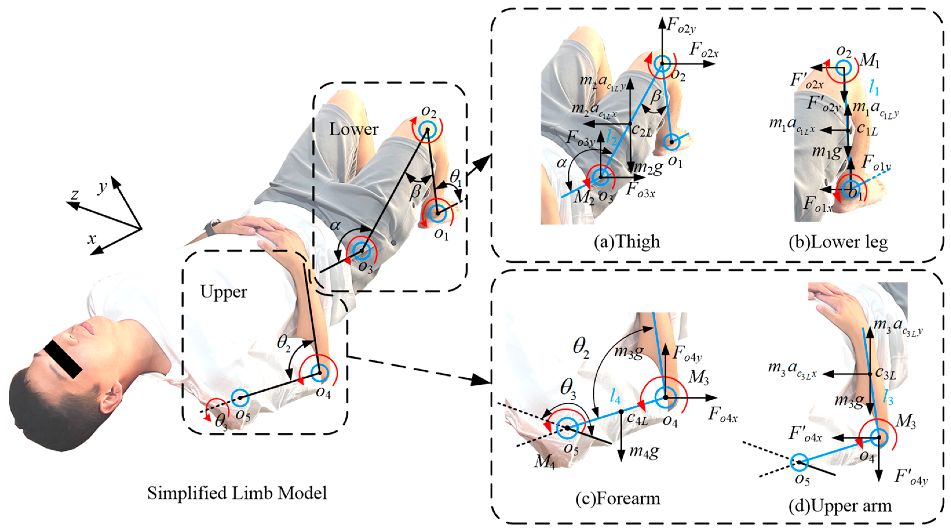
2.2. Modeling the Kinematics of Human Recumbent Limb Rehabilitation

Based on human anatomy, analyzing the forms of joint movements involves studying the joint torques generated by voluntary human movements. The human body system is simplified into a ball-and-stick model, and force analysis is conducted on each limb, as depicted in Figure 2. Since the movements on both sides of the human body are symmetrical, the analysis is only conducted on the right side of the body. Here, oi (i = 1, 2, 3, 4, 5), respectively, represented the ankle joint, knee joint, hip joint, elbow joint, and shoulder joint. The characteristic angles of the lower limbs, α, β, and θ1, represented the angles between the trunk and the thigh, the thigh and the lower leg, and the lower leg and the foot, respectively. These angles indicate the orientation of the lower limbs on a two-dimensional plane, not in three-dimensional space. The characteristic angles of the upper limbs, θ2 and θ3, represent the angle between the forearm and the upper arm, and the rotation angle of the upper arm around the x-axis, respectively. The mass of each limb segment was represented as mi, and its length was represented as li.
The geometric structures of various parts of the human body are irregular. Overall, it can be regarded as a system of rods. The positions of the centroids of each part are set at the geometric center of the rod. The centroids of each limb are denoted as ciL, and their moments of inertia are Jci.
Where acjLx and acjLy respectively represent the horizontal and vertical accelerations at the corresponding positions, Foix, Foiy, Foix, and Foiy respectively represent the horizontal and vertical components of the forces at each joint, g represents the acceleration due to gravity, M1 and M2 represented the torque at the right knee joint and right hip joint, respectively. During rehabilitation training, the motion process is relatively slow, resulting in inertial forces and Coriolis forces that are significantly smaller compared to other forces. Therefore, these forces are neglected in the simplified formulation. According to Figure 2b, the dynamic equation for the lower right leg is as follows [19]:
F o 2 x = 0 : F o 2 x + F o 1 x + m 1 a c 1 L x = 0 F o 2 y = 0 : F o 2 y + F o 1 y + m 1 a c 1 L y m 1 g = 0 M o 2 = 0 : J c 1 L α o 1 o 2 + M 1 + 0.5 m 1 g l 1 cos θ F o 1 y l 1 cos θ 1 + F o 1 x l 1 sin θ 1 0.5 m 1 a c 1 L y l 1 cos θ 1 + 0.5 m 1 a c 1 L x l 1 sin θ 1 = 0
In the equation, αoioi+1 represents the angular acceleration of the moving limb. Fo1x and Fo1y, respectively, denote the horizontal and vertical components of the force exerted on the right ankle joint from the ground. Similarly, according to Figure 2a, conducting dynamic analysis on the right thigh with the hip joint o3 as the origin of coordinates, we can obtain Equation (2).
F o 3 x = 0 : F o 2 x + F o 3 x m 2 a c 2 L x = 0 F o 3 y = 0 : F o 2 y + F o 3 y + m 2 a c 2 L y m 2 g = 0 M o 3 = 0 : J c 2 L α o 2 o 3 + M 2 0.5 m 2 g l 2 cos α + F o 2 y l 2 cos α F o 2 x l 2 sin α + 0.5 m 2 a c 2 L x l 2 cos α + 0.5 m 2 a c 2 L y l 2 sin α = 0
The dynamic model of the upper limbs is simplified into two parts: the upper arm and the forearm, as illustrated in Figure 2c,d. The upper arm undergoes rotational motion, with the elbow joint o4 serving as the reference origin for analyzing the forearm. The forearm undergoes rotational and lifting motion, with the shoulder joint o5 serving as the reference origin for analyzing the upper arm, where M3 and M4, respectively, represent the torque at the right elbow joint and the right shoulder joint, and αo4 represents the angular acceleration of the right shoulder. According to Figure 2c, the dynamic equation for the right forearm is as follows:
F o 4 y = 0 : F o 4 y m 3 g + m 3 a c 3 L y = 0 F o 4 x = 0 : F o 4 x m 3 a c 3 L x = 0 M o 4 = 0 : J c 3 L 1 α o 4 + M 3 0.5 m 3 g l 3 sin θ 2 + 0.5 m 3 a c 3 L y l 3 sin θ 2 0.5 m 3 a c 3 L y l 3 cos θ 2 = 0
The center of mass for the shoulder joint torque M4 is located at the shoulder joint, but the moment of inertia for the forearm is not centered there. By applying the parallel-axis theorem for moments of inertia, we can perform a moment of inertia transformation. This yields equations for the moment of inertia and the torque for the shoulder joint, which are expressed as Equations (4) and (5), respectively.
J o 4 = J c 4 L + J c 3 L 2 + m 3 l 4 2
M 4 = J o 4 α o 4
Solving Equations (1)–(5) simultaneously and rearranging, we obtain the following:
M 1 = J c 1 L α o 1 o 2 0.5 m 1 g l 1 cos θ 1 + F o 1 y l 1 cos θ 1 F o 1 x l 1 sin θ 1 + 0.5 m 1 a c 1 L y l 1 cos θ 1 0.5 m 1 a c 1 L x l 1 sin θ 1 M 2 = J c 2 L α o 2 o 3 + 0.5 m 2 g l 2 cos θ 1 + ( F o 1 y + m 1 a c 1 L y m 1 g ) l 1 cos θ 1 + ( F o 1 x + m 1 a c 1 L x ) l 1 sin θ 1 0.5 m 2 a c 2 L x l 2 cos α 0.5 m 2 a c 2 L y l 2 sin α M 3 = J c 3 L 1 α o 4 + 0.5 m 3 g l 3 sin θ 2 0.5 m 3 a c 3 L y l 3 sin θ 2 + 0.5 m 3 a c 3 L y l 3 cos θ 2 M 4 = J o 4 α o 4
To verify the accuracy of the kinematic analysis derived for supine limb rehabilitation movements, dynamic simulation experiments were conducted using Adams 2018. A simplified human model was established as depicted in Figure 3. The initial parameters for simulation and the joint connections were configured, and materials for each part were set according to their relative mass by specifying the actual materials. The angular velocity data obtained from motion capture were processed to calculate the angular accelerations of the hip, knee, ankle, elbow, and shoulder joints. These data were then subjected to sixth-order polynomial fitting using software to obtain three joint angular acceleration functions. These functions were utilized as inputs for angular acceleration in the rotational drive. Setting the simulation time to 5 s with a time step of 0.01, we obtained the simulation results for the variation in joint torques of the supine human body.

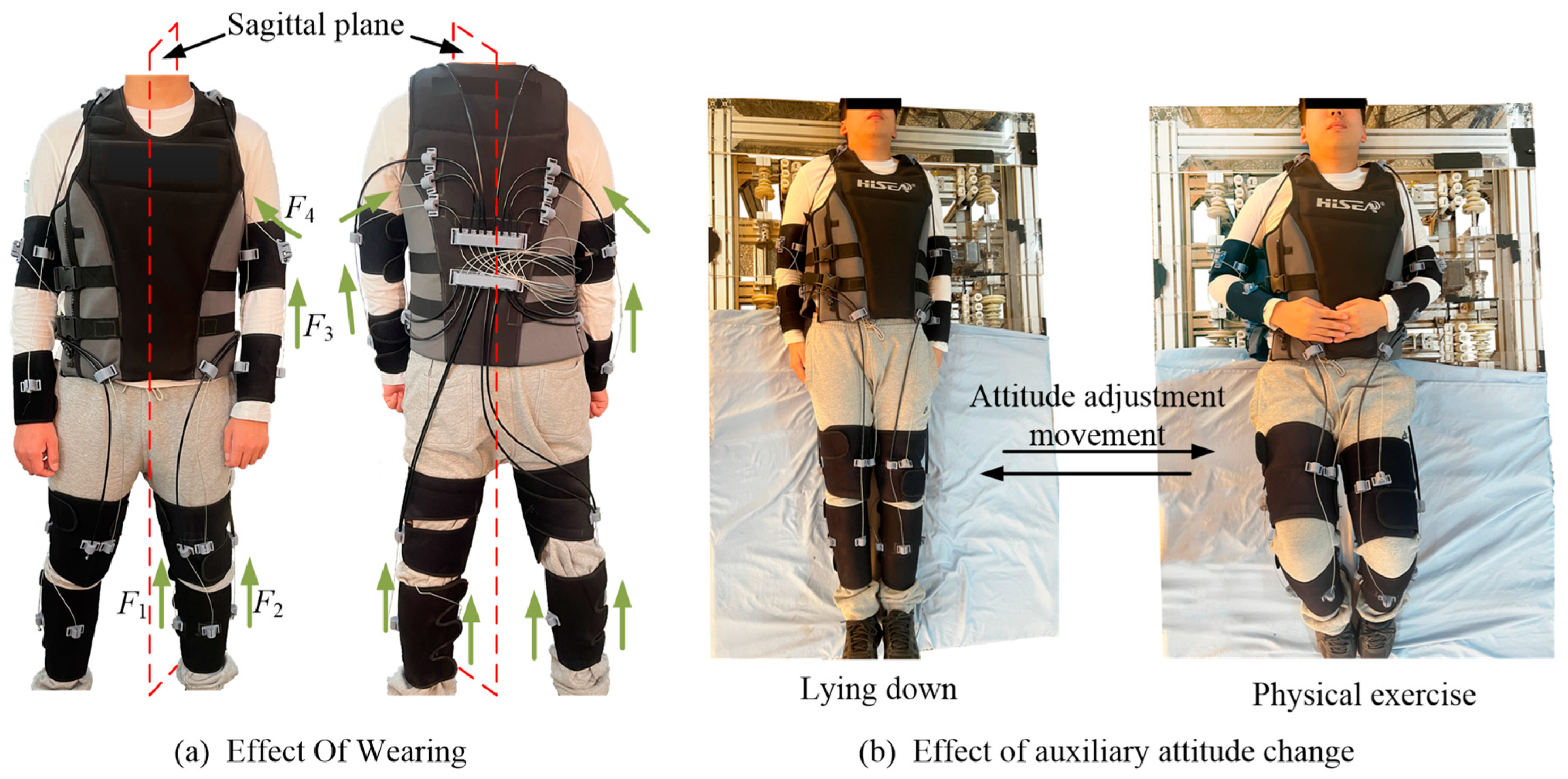
2.3. Design and Verification of a Wearable Multi-Posture Robot

Based on the patterns of joint torque variation during active movements in the supine position, a mechanism configuration for supine rehabilitation training devices was developed. With adherence to the physiological structure of the human body, it should exhibit high flexibility while minimizing constraints on joint mobility as much as possible. The designed wearable rehabilitation training device utilized straps with a rough outer surface and elasticity as the substrate, closely adhering to the surface of the limb. This enhanced the friction between the wearable garment and the skin surface, reducing positional displacement between the limb and the skin during movement. Building upon this and referencing the body morphological structure close to the average values of height, weight, and body shape of Chinese males [20], the wearable garment and the straps in contact with the human body adopted an adjustable wrapping method to accommodate different limb sizes. Additionally, the driving unit’s retraction stroke was designed with ample allowance to address discrepancies in height, which may lead to inconsistent initial distances of the wire ropes. This results in the design of a wearable supine rehabilitation training device with strong envelopment and high comfort, as illustrated in Figure 4.
The structure of this supine position limb rehabilitation training device is mainly composed of a circuit module and a drive module. The circuit module consists of wearable limb straps made of flexible textiles, which are characterized by light weight, good flexibility, and low rigidity. The straps are firmly fixed with Velcro to prevent secondary harm to the body. In Figure 4, the red dot and dashed line represent the wire rope, and the red thick solid line represents the outer tube. The starting end of the wire rope is connected to each strap, and the wire ropes from different limbs meet at point “a” behind the bundle block through the Bowden cable. The wire separator separates the wire rope from the outer tube and then connects the end of the wire rope to the winding pulley in the drive module. The winding pulley is located at both ends of the drive motor and can be used as both a take-up pulley and a payout pulley. In the state of the wearer, the drive motor rotates the winding pulley through the bevel gear, thereby pulling the wire rope to contract, thereby inducing the limb end to perform rehabilitation movement.
Based on the supine limb rehabilitation training device, a prototype of the device is manufactured and assembled, and volunteers are invited to demonstrate wearing it, as shown in Figure 5. Figure 5a depicts the routing of each limb after volunteers wore the device, with limbs symmetrically distributed. Figure 5b shows the prototype experiment of the device during training, where volunteers’ limbs undergo wide-range movements, following the movement of the traction ropes, resulting in significant motion effects. Throughout the process, the movement of the limbs is smooth, and volunteers report no discomfort. The prototype experiment is conducted following the same method of collecting limb movements as illustrated in Figure 1.
To verify the compatibility and rationality of the institutionalized movement forms with the trajectory of human bodily movements, an analysis of the joint torques generated by devices during passive human motion was conducted. The verification of joint torques at human limb movement joints was due to the tension exerted by surrounding muscle tissues, thereby emphasizing the significance of bodily limb training in effectively enhancing muscle strength and explosiveness at the joint segments [21]. To promote the development and improvement of muscle strength and explosiveness around each joint of the limbs, the study examined whether the limb supine rehabilitation training device could meet the rehabilitation requirements of various limbs in the human body. During passive limb rehabilitation exercises, wherein rehabilitation activities were carried out by wearing the rehabilitation training device, limb movements were achieved by the manipulation of designated limbs through steel wire ropes. Based on the predetermined fixed positions of the steel wire rope ends, a modeling analysis of the driving joint torque was conducted, as illustrated in the following figure.
According to the established model, assumptions were made regarding the limbs and joints of the human body: the action binding straps of each limb were approximated as cylinders or rectangular prisms with radii denoted as bi (i = 1, 2, …, 7); the elbow and knee joints of the human body were approximated as rotational pairs with radii of rotation denoted as Re and Rk, respectively; ai represented the distance from the limb binding strap location to the adjacent joint pivot center oj (j = 1, 2, 3, 4).
During the analysis, establish the coordinate system as depicted in Figure 6d at the joint locations, where oj coincides with the pivot center of each joint. Parameters such as ai and bi are represented according to the direction of the established coordinate system. By analyzing each joint in the figure, the direction vector of the driving tension Fj at each joint can be obtained as follows:
P F j = a i sin α i + b i cos α i + + b i + 1 cos α i + 1 a i cos α i + b i sin α i + + b i + 1 sin α i + 1
The force point vector was expressed as follows:
P p j = a i sin α i + b i cos α i a i cos α i + b i sin α i
In the equation, Ppj denotes the initial position and direction vector of the tension force Fj.
The joint torque was then given by the following:
T j = P p j × P F j P F j F j
To avoid the impact of Bowden cable wear on mechanical properties, the Bowden cable was regularly replaced during the experiments, and a relatively basic mechanical model was established. Through the analysis of the movement processes of each limb, expressions for the variation in wire rope torques in different limb segments were obtained. Here, ai and bi were obtained through measurement and were constant. Length-related data were measured using an optical motion capture system, while force values were obtained through calculation based on the established mechanical model and indirectly acquired using a cable tension sensor in other related studies.

3. Results

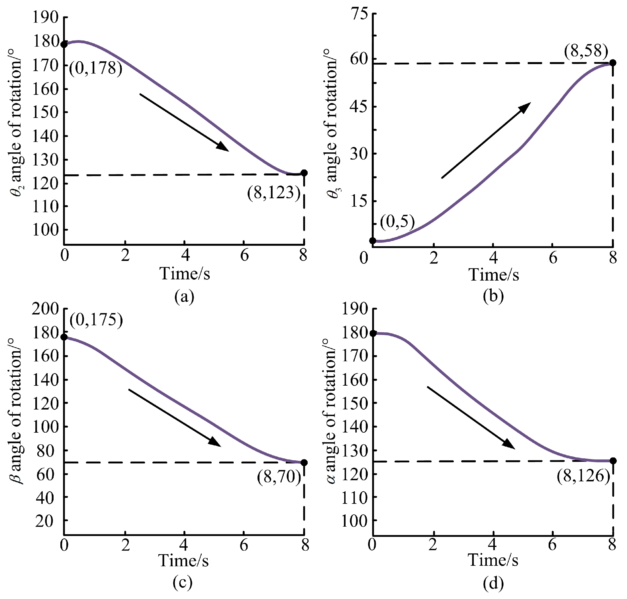
3.1. Theoretical Data Solution

Performing joint torque analysis for human supine limb rehabilitation movements involves incorporating velocity, acceleration, and angular data of various marker points, along with human body parameters, into the derived joint torque formula (Equation (6)). The human body parameters are shown in Table 1.
After processing the results, we obtained the comparison between the active and passive torques generated during the motion process, as shown in Figure 7. From Figure 7a,c,d, it can be observed that the shaded area represents the angular momentum generated during limb movement, which accumulates over time during the movement process. This can be used to describe changes in the rotational state of the object and can serve as an indicator to assess the effectiveness of rehabilitation training. The torque-calculated values and the simulated values exhibit some differences in trend. However, the magnitudes of the torque generated by limb movement are consistent. The reason for the difference in trends is that contact is set during simulation to make it more consistent with real situations. This can lead to reduced torque requirements during limb movement as adjacent limbs encounter each other.
During the rehabilitation training process, the forearm is naturally positioned against the torso, and the feet are in contact with the bed surface, providing auxiliary support for joint movement. The torque values shown in the figure represent only the variations during the joint flexion process. The magnitude of the rotational torque for the forearm and upper arm is smaller compared to lower limb movements, primarily ranging from 0 to 4 Nm. The active torque valued for the forearm exhibits fluctuation, mainly due to non-uniform motion, with torque values varying within the range of 0 to 1.5 Nm. The steep fluctuations in the active motion curve are attributed to the intermittent nature of arm movement during the rotation experiment of the upper arm. There are instances where the arms are lifted to achieve the desired measurement values. Regarding lower limb movement, as the limbs underwent flexion during leg bending exercises, the resistance increased due to muscle compression, leading to an increase in the required torque to drive the limb. The active torque values for rotation of the lower leg increase from around 10 Nm in the supine position to approximately 37 Nm when the knee is flexed. Similarly, the active torque values for rotation of the thigh increase from around 10 Nm to approximately 40 Nm. The significantly higher torque requirement for thigh movement compared to lower leg movement is attributed to the fact that thigh movement also involves driving the movement of the lower leg, and the weight of the thigh is much greater than that of the lower leg.
The joint torque curves during supine training exercises reveal distinct patterns: initially, there is a rapid increase in torque, followed by a period of stability, and then a steep increase toward the end. At the onset of movement, the rapid increase in torque reflected the need for muscles to overcome static inertia to accelerate the body. This necessitates significant joint torque to initiate movement. Additionally, coordination among body parts is required to initiate an effective movement pattern. As the body accelerates to a certain extent, the movement stabilizes. At this point, muscle force is primarily directed toward maintaining the current speed and direction, countering air resistance and other persistent external forces. Hence, joint torque changes during this phase were relatively smooth, reflecting the stability of the muscle force output. As the movement approaches its end, the body needs to decelerate to a stop or change direction rapidly. The muscles are required to quickly adjust force output, generating large reverse torques to decelerate the body. Simultaneously, to maintain balance and prepare for the cessation of movement, additional adjustments across the body may further increase torque variability. In summary, the variation in joint torque during movement reflects muscle adjustments for movement control and the body’s response to different stages of movement. Analysis of joint torque variation during the stable phase revealed that the comfort zone lay mainly between 15° and 45°. To optimize the efficacy of rehabilitation training for comfort, it is advisable to set the range of motion within this interval. Research on the patterns of joint torque variation in the human body was crucial for enhancing performance and preventing sports injuries.

3.2. Motion Capture and Force Sensing Experimental Analysis

For different groups of data in motion capture experiments, singular value exclusion processing was conducted before summation averaging [22]. This process yields the general movement trajectories for each experimental group. One trajectory was selected as the subject of the posture adjustment experiment analysis. During active posture adjustment of the human body, the limb movement angles in the xy plane vary with time. Experimental data were collected and processed using MATLAB 2019b for polynomial fitting to obtain angle-time functions for each limb. The second derivative of these functions was then calculated to derive acceleration-time functions, as illustrated in Figure 8a–d. The curves illustrating the variation in the ground reaction forces Fo1x and Fo1y in the foot with time are depicted in Figure 8e and Figure 8f, respectively. The upper limb movement is completed within 4 s, while the lower limb movement takes 8 s to complete. Measurements of angles are taken from the supine position to the end of the posture adjustment. It is challenging to achieve uniform motion throughout the human movement process, resulting in slight oscillations in the overall trend of limb movements and fluctuations in angular acceleration.
At the point of the ground reaction force at the foot, Fo1x is primarily influenced by friction between the foot and the six-axis force platform during movement, while Fo1y is a result of the weight of the lower limbs. As the lower limbs move slowly, the limbs experience acceleration in both the x and y directions. Consequently, this leads to variations in the magnitudes of Fo1x and Fo1y. Fo1x gradually increases, reaching a maximum value of around 70 N (point A). This increase is attributed to continuous contact between the foot and the thin film covering the platform surface. As the foot moves, friction between the foot and the film generates heat, causing an increase in temperature at the contact point. With stronger atomic forces between the materials, the frictional force increases. On the other hand, Fo1y initially increases and then decreases, reaching a peak value of approximately 30 N (point B) during the initial phase. This decrease is due to the upward acceleration component of the leg, causing a reduction in the applied force and thus resulting in a decrease in the measured value of Fo1y. Upon reaching the termination state (points A and C), when the posture adjustment movement concludes, both Fo1x and Fo1y rapidly decrease. The force exerted on the limbs during movement differs significantly from that during static states. Therefore, when designing rehabilitation robots, it is essential to consider variations in force magnitude resulting from human movement, which can enable patients to engage in more effective rehabilitation training [23].

3.3. Experimental Analysis of the Prototype of Recumbent Rehabilitation Training Device
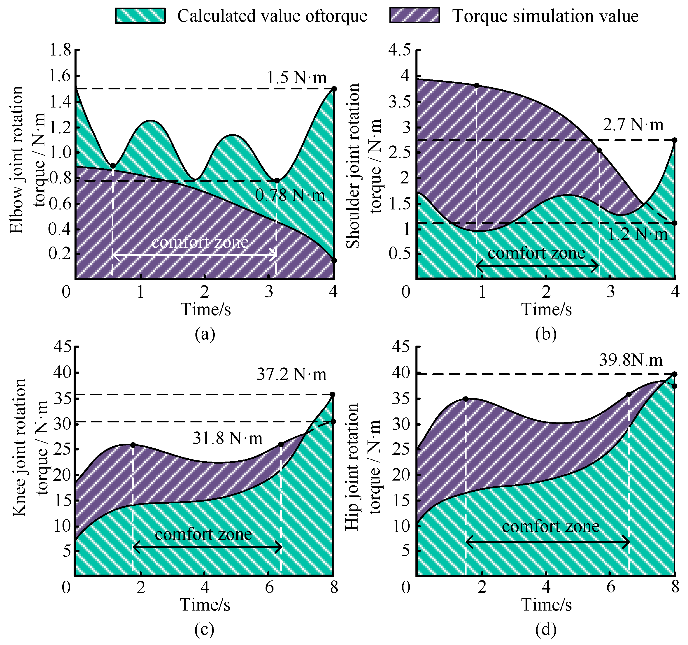
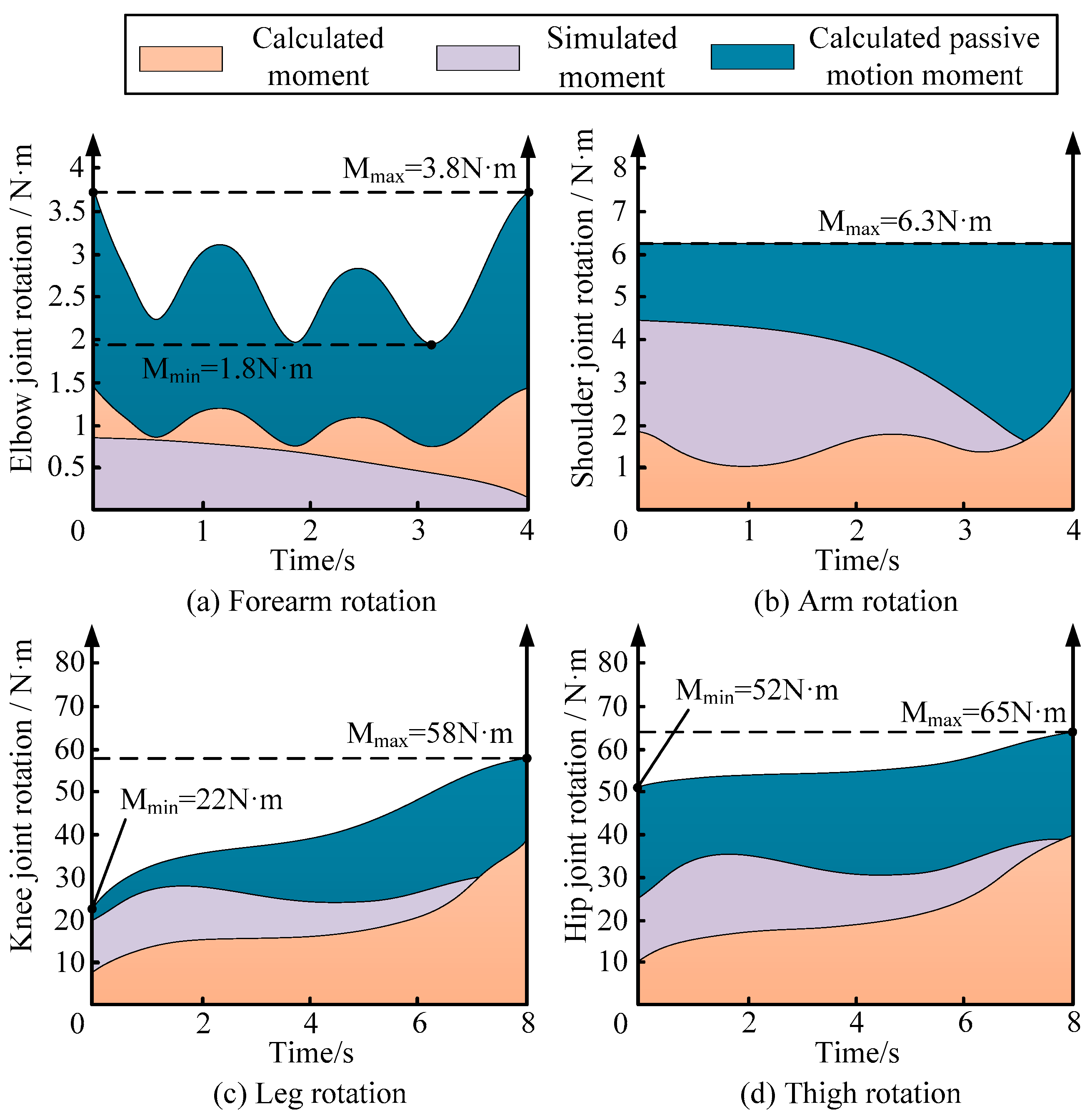
The motion–time and angular variation graph between the limb and the rehabilitation device in the supine position is depicted in Figure 9. Figure 9a–d represent the changes in the elbow, shoulder, hip, and knee joints over time. The device’s motion time is set to complete within 8 s. Analysis of the human limb motion curves obtained through prototype experiments reveals that there is no significant change in the limb angles during the initial few seconds. This indicates a relative lag in limb movement compared to device motion, attributed to a certain response time inherent in the device’s propulsion of human movement. Throughout the entire motion process, the human limb angular variation curves exhibit smooth transitions, achieving approximately 60° rotation of the upper arm, 60° elevation of the forearm, 60° elevation of the thigh, and around 60° flexion of the lower leg. This demonstrates good stability in human–device cooperative motion.

3.4. Verification

Based on studies related to the dynamics of voluntary human movement [24], the angular variations in shoulder, elbow, hip, and knee joints over time during bedridden limb movement were computed. These variations corresponded to the set force values of the respective assistive traction ropes and were incorporated as parameters into Equation (9) to obtain the joint torques during passive human motion as illustrated in Figure 10.
This variation is attributed to the fluctuation in the force applied by the external traction rope on the forearm throughout the motion, resulting in torque fluctuations, with a maximum force of approximately 3.5 Nm. Conversely, during the rotational motion of the upper arm, the torque remains constant at 6.3 Nm. This consistency is due to the fixed position of the traction rope’s action on the upper arm during rotation, unlike in other limb movements where the traction rope force varies continuously, as depicted in Figure 10b F2. In the case of lower limb movements, the passive torque for the rotation of the lower leg increases from around 20 Nm to approximately 60 Nm. Similarly, the torque for lower leg rotation increases from about 50 Nm to around 70 Nm. Comparing the joint torque of passive and active movements in the human body, it is observed that the trend of torque variation in limb passive and active movements is similar.
The sample size was increased to 30 using the same method, and hypothesis testing was conducted using the p-value approach. The null hypothesis (H0) states that there is no significant difference between the passive torque and active torque, whereas the alternative hypothesis (H1) posits that the passive torque is significantly greater than the active torque. Since the passive torque and active torque were obtained through different methods, they are assumed to be independent samples. An independent samples t-test was performed to compare the mean differences between the passive torque and active torque. The results of the test are presented in Table 2.
From the statistical results in Table 2, the passive torque values significantly exceed the active torque values. During rehabilitation training, the torque generated by the device can be adjusted to match the patient’s voluntary movement torque. This allows the patient’s limb to be driven by the device for specified movements, facilitating the restoration of limb movement. When the torque generated by the device surpasses the patient’s active movement torque, the patient’s limb counteracts the device-generated torque, thereby enhancing the effectiveness of muscle training during rehabilitation. Additionally, when the torque generated by the device exceeds the calculated and simulated values, the rehabilitation training device proves to be effective in facilitating recovery.

4. Discussion

Wearable robots constitute an extremely complex system, and research in this domain is not limited to structural design and mechanism control. The focus of structural design is on safety and human–robot compatibility, ensuring that the robot, when worn on the human body, can be quickly detached in emergencies to prevent harm. It is also essential to align the robot’s movements with human motion capabilities, avoiding actions that could result in strain or injury. To meet these objectives, some researchers have utilized multi-sensor fusion technologies at the control level [25]. However, control systems are inherently susceptible to failure, leading other scholars to explore the development of flexible wearable robots to inherently ensure these objectives through hardware design [26]. Nonetheless, the flexibility of such robots poses challenges in achieving precise mechanical movements, especially for rehabilitation robots intended for disabled individuals. Disabled individuals often cannot communicate their sensations intuitively, which may result in serious consequences.
Current research on rehabilitation robots mainly concentrates on the dynamics of the mechanisms, where parameters are set to verify the robot’s ability to drive the human body to predetermined positions [27]. However, for the human body, the essence of rehabilitation training lies in joint movement, specifically, whether the set parameters can provide sufficient joint torque to autonomously drive limb movement and effectively exercise the relevant local muscles. Existing studies lack a comparative analysis between the parameters set for driving the human body and those required for joint-driven limb movement in the human body.
During the rehabilitation of disabled individuals, regular supine lateral turning can effectively prevent pressure ulcers. Adopting a reasonable posture for lateral turning can significantly reduce the operational wear and tear of the robot. To this end, motion capture and force measurement experiments were conducted to obtain accurate human joint motion parameters. Utilizing the principle of torque balance, the active joint torques of the human body were analyzed and simulated, yielding the maximum joint torques during supine limb rehabilitation movements. Based on the analyzed active joint torque characteristics and anatomical theories, a supine rehabilitation training device was further developed to provide training intensity adapted to the patient’s motor capabilities. The developed robot can effectively assist disabled individuals in turning over, enhancing the interpretability of human posture, and holds significant importance for the field of medical rehabilitation.

5. Conclusions

To meet the need for regular limb movement in bedridden patients with disabilities, a dynamic model of limb joint motion was established based on the principle of torque balance and the sagittal plane joint angle relationships of human limbs. By studying limb movements in the supine position, the active and passive joint torques of the human body were analyzed through experiments and simulation calculations. The analysis of motion trajectories and curve results during human–robot collaborative movement demonstrated that the designed supine limb rehabilitation training device exhibits stable collaborative motion performance and high comfort during operation. This study provides a theoretical foundation for the optimization of limb rehabilitation motion mechanisms and offers valuable insights for the design of other supine rehabilitation robots. The findings hold practical significance for bedridden rehabilitation applications.

Author Contributions

Conceptualization, Q.W., P.S. and Y.L.; methodology, Y.L.; software, S.W.; validation, Q.W., C.S. and Y.L.; formal analysis, Q.W.; investigation, Q.W.; resources, Y.L.; data curation, S.W.; writing—original draft preparation, Q.W. and Y.L.; writing—review and editing, C.S.; visualization, Q.W. and J.L.; supervision, J.L.; project administration, P.S.; funding acquisition, P.S. All authors have read and agreed to the published version of the manuscript.

Funding

This research was funded by the Ministry of Civil Affairs rehabilitation field key laboratory and engineering technology research center operating expenses project, grant number 102118170090010009004.

Data Availability Statement

Data are contained within the article.

Acknowledgments

The authors would like to express their sincere gratitude to the anonymous reviewers for their valuable suggestions.

Conflicts of Interest

The authors declare that this study received funding from Ministry of Civil Affairs rehabilitation field key laboratory and engineering technology research center operating expenses project. The funder had the following involvement with the study: Innovative design of human-machine motion collaborative supine rollover assisted robot.

References

  1. Trebbi, A.; Mukhina, E.; Rohan, P.-Y.; Connesson, N.; Bailet, M.; Perrier, A.; Payan, Y. MR-based quantitative measurement of human soft tissue internal strains for pressure ulcer prevention. Med. Eng. Phys. 2022, 108, 103888. [Google Scholar] [CrossRef]
  2. Sakamoto, D.; Hamaguchi, T.; Murata, K.; Ito, H.; Nakayama, Y.; Abo, M. Upper Limb Function Recovery by Combined Repetitive Transcranial Magnetic Stimulation and Occupational Therapy in Patients with Chronic Stroke According to Paralysis Severity. Brain Sci. 2023, 13, 284. [Google Scholar] [CrossRef]
  3. Fabulas, F.; Paisant, P.; Dinomais, M.; Mucci, S.; Casa, C.; Le Naoures, P.; Hamel, J.F.; Perrot, J.; Venara, A. Pre-habilitation before colorectal cancer surgery could improve postoperative gastrointestinal function recovery: A case-matched study. Langenbeck’s Arch. Surg. 2022, 407, 1595–1603. [Google Scholar] [CrossRef] [PubMed]
  4. Qassim, H.M.; Wan Hasan, W.Z. A review on upper limb rehabilitation robots. Appl. Sci. 2020, 10, 6976. [Google Scholar] [CrossRef]
  5. Fareh, R.; Elsabe, A.; Baziyad, M.; Kawser, T.; Brahmi, B.; Rahman, M.H. Will Your Next Therapist Be A Robot?—A Review of the Advancements in Robotic Upper Extremity Rehabilitation. Sensors 2023, 23, 5054. [Google Scholar] [CrossRef] [PubMed]
  6. Gu, J.; Xu, C.; Liu, K.; Zhao, L.; He, T.; Sun, Z. Impedance Control of Upper Limb Rehabilitation Robot Based on Series Elastic Actuator. In Proceedings of the International Conference on Intelligent Robotics and Applications, Harbin, China, 1–3 August 2022; Springer International Publishing: Cham, Switzerland, 2022; pp. 138–149. [Google Scholar]
  7. Akdoğan, E.; Adli, M.A. The design and control of a therapeutic exercise robot for lower limb rehabilitation: Physiotherabot. Mechatronics 2011, 21, 509–522. [Google Scholar] [CrossRef]
  8. Guzmán-Valdivia, C.; Blanco-Ortega, A.; Oliver-Salazar, M.; Gómez-Becerra, F.; Carrera-Escobedo, J. HipBot–The design, development, and control of a therapeutic robot for hip rehabilitation. Mechatronics 2015, 30, 55–64. [Google Scholar] [CrossRef]
  9. Yepes, J.C.; Rúa, S.; Osorio, M.; Pérez, V.Z.; Moreno, J.A.; Al-Jumaily, A.; Betancur, M.J. Human-Robot Interaction Torque Estimation Methods for a Lower Limb Rehabilitation Robotic System with Uncertainties. Appl. Sci. 2022, 12, 5529. [Google Scholar] [CrossRef]
  10. Pang, Z.; Wang, T.; Wang, Z.; Yu, J.; Sun, Z.; Liu, S. Design and analysis of a wearable upper limb rehabilitation robot with characteristics of tension mechanism. Appl. Sci. 2020, 10, 2101. [Google Scholar] [CrossRef]
  11. Jorge, D.R.; García, J.B.; Jayakumar, A.; Moreno, R.L.; Ortiz, R.A.; Sánchez, F.R. Force and torque characterization in the actuation of a walking-assistance, cable-driven exosuit. Sensors 2022, 22, 4309. [Google Scholar] [CrossRef]
  12. Li, Y.; Zi, B.; Yang, Z.; Ge, J. Combined kinematic and static analysis of an articulated lower limb traction device for a rehabilitation robotic system. Sci. China Technol. Sci. 2021, 64, 1189–1202. [Google Scholar] [CrossRef]
  13. Zhang, L.; Jiao, Z.; He, Y.; Su, P. Ergonomic design and performance evaluation of H-suit for human walking. Micromachines 2022, 13, 825. [Google Scholar] [CrossRef]
  14. Wu, X.; Bai, S.; O’Sullivan, L. Editorial for the special issue on wearable robots and intelligent device. Biomim. Intell. Robot. 2023, 3, 100102. [Google Scholar] [CrossRef]
  15. Lu, H.; Wang, H.B.; Feng, Y.F. Human-machine Coupling Dynamics Modeling and Active Compliance Control of Lower Limb Rehabilitation Robot. J. Mech. Eng. 2022, 58, 32–43. [Google Scholar]
  16. Sun, H.Y.; Zhang, L.X.; Wang, L. Dynamics modeling and control of horizontal lower limbs rehabilitation robot. Chin. High Technol. Lett. 2010, 6. [Google Scholar]
  17. Li, Y.; Zi, B.; Zhou, B.; Zhao, P.; Ge, Q.J. Cable angle and minimum resultant force response analysis of lower limb traction device for rehabilitation robot with interval parameters. J. Comput. Inf. Sci. Eng. 2021, 21, 021002. [Google Scholar] [CrossRef]
  18. Lang, A.E.; Kim, S.Y.; Milosavljevic, S.; Dickerson, C.R. The utility of the acromion marker cluster (AMC) in a clinical population. J. Electromyogr. Kinesiol. 2022, 62, 102298. [Google Scholar] [CrossRef]
  19. Andrews, J.G. Biomechanical analysis of human motion. Kinesiology 1974, 4, 32–42. [Google Scholar]
  20. Muscolino, J.E. Kinesiology-E-Book: The Skeletal System and Muscle Function; Elsevier Health Sciences: Amsterdam, The Netherlands, 2010. [Google Scholar]
  21. Jiang, D.; Liu, Z.; Ling, X.; Dai, J.; Long, L.; Lu, Y.; Zhou, S. Investigating the impact of inter-limb asymmetry in hamstring strength on jump, sprint, and strength performance in young athletes: Comparing the role of gross force. Front. Physiol. 2023, 14, 855. [Google Scholar] [CrossRef]
  22. Jin, Y.; Zhou, Y.M.; McCann, C.M.; Proietti, T.; Rycroft, C.H.; Walsh, C.J. A Data-based Approach to Simultaneously Align Local and Global Frames between an Inertial Measurement Unit (IMU) and an Optical Motion Capture System. In Proceedings of the 2022 9th IEEE RAS/EMBS International Conference for Biomedical Robotics and Biomechatronics (BioRob), Seoul, Republic of Korea, 21–24 August 2022; IEEE: Piscataway, NJ, USA, 2022; pp. 1–8. [Google Scholar]
  23. Zhang, L.; Song, G.; Zou, C.; Huang, R.; Cheng, H.; Hu, D. Modulation for Impact Reducing of Lower-Limb Exoskeletons. Micromachines 2022, 13, 816. [Google Scholar] [CrossRef]
  24. Liu, Y.; Su, P.; Lun, Q.; Zhang, Y.; Zhang, Q. Design and Simulation of a Flexible Mechanism for Wearable Assisted Posture Adjustment. In Proceedings of the 2023 IEEE 13th International Conference on CYBER Technology in Automation, Control, and Intelligent Systems (CYBER), Qinhuangdao, China, 11–14 July 2023; IEEE: Piscataway, NJ, USA, 2023; pp. 859–864. [Google Scholar]
  25. Li, Q.; Wang, S.; Wang, C.; Zhu, J. Editorial for the special issue on bio-inspired robotic dexterity intelligence. Biomim. Intell. Robot. 2024, 4, 100186. [Google Scholar] [CrossRef]
  26. Walsh, C. Human-in-the-loop development of soft wearable robots. Nat. Rev. Mater. 2018, 3, 78–80. [Google Scholar] [CrossRef]
  27. Chen, G.; Peng, W.; Wang, Z.; Tu, J.; Hu, H.; Wang, D.; Cheng, H.; Zhu, L. Modeling of swimming posture dynamics for a beaver-like robot. Ocean Eng. 2023, 279, 114550. [Google Scholar] [CrossRef]
Figure 1. Exercise experiments in recumbent rehabilitation training.
Electronics 14 01724 g001
Figure 2. Analysis of limb forces in human recumbent exercises.
Electronics 14 01724 g002
Figure 3. The human supine limb movement simulation model.
Electronics 14 01724 g003
Figure 4. Modeling of the limb rehabilitation training device.
Electronics 14 01724 g004
Figure 5. Prototype and experimental diagram of horizontal limb rehabilitation training device.
Electronics 14 01724 g005
Figure 6. Driving joint moment analysis diagram.
Electronics 14 01724 g006
Figure 7. (ad) Comparison of joint moments for limb movement in the lying position. The blue area represents the angular impulse corresponding to the calculated torque, with the background hatch lines in the blue area having a negative slope. The purple area represents the angular impulse corresponding to the simulated torque, with the background hatch lines in the purple area having a positive slope. The comfort zone indicates a region of relatively stable torque where there are no significant sudden increases or decreases in torque.
Electronics 14 01724 g007
Figure 8. Prototype Body motion curve and ground reaction force curve.
Electronics 14 01724 g008
Figure 9. Sample machine driving limb movement angle change curve.
Electronics 14 01724 g009
Figure 10. Moment diagram of human passive motion joints.
Electronics 14 01724 g010
Table 1. Mass and length parameters of human body parts.
Body PartQuantity/kgLength/m
Calf2.60.37
Thigh9.20.425
Lower arm0.850.26
Table 2. Significance testing of joint rotation.
Test StatisticsShoulderElbowKneeHip
t-test df45.247.852.355.6
p-value<0.0001<0.0001<0.0001<0.0001
Disclaimer/Publisher’s Note: The statements, opinions and data contained in all publications are solely those of the individual author(s) and contributor(s) and not of MDPI and/or the editor(s). MDPI and/or the editor(s) disclaim responsibility for any injury to people or property resulting from any ideas, methods, instructions or products referred to in the content.

