1. Introduction
In recent years, Location-Based Services (LBSs) have become ubiquitous in our daily lives, providing geographic context in real time for many application fields such as navigation, social networking, or entertainment, among others. The emergence of the Internet of Things (IoT), with thousands of devices connected to the Internet that are capable of collecting, processing, and sharing data, has boosted interest in LBSs even further [
1]. IoT devices, ranging from wearable fitness trackers to industrial sensors, often depend on accurate location data to function properly. In smart cities, for instance, IoT-enabled traffic management systems use location information to reduce congestion, while public transport systems provide real-time updates to passengers. Similarly, in healthcare, IoT devices can aid in tracking the location of medical equipment, patients, and staff within hospitals, ensuring the continuous monitoring of a patient’s health and timely response in critical situations.
While LBSs provide numerous benefits, they also raise a number of security and privacy concerns. One of the primary security risks is the exposure of sensitive location data [
2], which can be intercepted, stolen, or misused by malicious actors to track users or devices. In addition, location data can also reveal information about a user’s preferences, habits, or condition, leading to a breach of privacy. Another major security issue is the vulnerability of the positioning systems used in LBSs to spoofing and tampering attacks [
3]. Adversaries can manipulate or forge location data to disrupt the operation of such systems, leading to incorrect position estimations. In critical sectors like healthcare or emergency services, where accurate location data are vital, such disruptions could have severe consequences.
Among the existing location techniques, the Global Navigation Satellite System (GNSS) and, in particular, Global Positioning System (GPS) has prevailed for outdoor positioning. However, it is well known that these techniques exhibit many limitations in indoor environments [
4]: GPS signals struggle to penetrate walls and ceilings, often resulting in weak or nonexistent signals. Signal degradation and the multipath effect due to signal reflection on walls or other obstacles lead to a drastic reduction in the system’s accuracy in terms of positioning error. In addition, the use of GNSS increases energy consumption, making it unsuitable for battery-limited devices such as the ones in the IoT ecosystem. As a consequence, other technologies like Wi-Fi, Radio Frequency Identification (RFID), and Bluetooth Low Energy (BLE) have been proposed to enhance accuracy in indoor positioning [
1].
Nowadays, an indoor positioning technique must not only provide accurate estimations but also be easy to use in common off-the-shelf (COTS) devices. This is why research has increasingly focused on technologies commonly supported by smartphones, tablets, smartwatches, and similar devices—primarily IEEE 802.11 (Wi-Fi) and BLE. With 60% of Internet traffic traveling through Wi-Fi, this technology remains the most widely used for browsing [
5]. Therefore, to avoid deploying new infrastructure specifically for localization and to reduce costs, choosing Wi-Fi-based positioning solutions appears to be a natural choice [
6].
Nevertheless, the design of ranging methods for Wi-Fi environments also pose some challenges regarding latency and bandwidth consumption: on the one hand, the location process should be fast enough to allow a device to obtain its position in real time. On the other hand, the exchange of location information should not result in network congestion or in an excess of bandwidth consumption to the detriment of user traffic. The fine timing measurement (FTM) procedure, defined in the IEEE 802.11mc standard [
7], is intended to provide ranging functionalities to stations willing to estimate their position while meeting these requirements. As a consequence, security issues such as location privacy have been left in the background. The procedure was designed to be performed without the need for a station to associate to an access point (AP), and therefore, there is no AP authentication. Lack of authentication allows for any attacker to set up a rogue AP [
8,
9], establish an FTM session with a station, and lead it to a wrong position estimation by reporting false data. Other security services such as data confidentiality or data integrity are not considered either. All messages exchanged between the station and the AP are sent in the clear, which causes a privacy breach since any adversary in the range can eavesdrop on the communication [
10,
11].
However, users are increasingly becoming more aware of the importance of protecting their data against third parties, and thus, there is a need to include security mechanisms within the positioning methods. The concept of Privacy by Design (PbD) [
12] aims at enhancing sensibility regarding data protection and describes an approach to include considerations regarding privacy and data protection into Information Technology (IT) systems and technological products at an early stage of their development. Recently, IEEE 802.11az [
13] (Amendment for Enhancements for Positioning) was released, aiming to protect the FTM procedure through encryption and AP authentication. However, its practicality is questionable when the FTM procedure is applied in public venues, where no cryptographic material is shared in advance between users and network infrastructure [
14]. In addition, the introduction of encryption and authentication mechanisms increases the overhead, thus decreasing the available bandwidth. Also, while being issued in 2023, devices integrating IEEE 802.11az will take time to be available on the market, thus still requiring work on the currently available implementation of FTM.
The literature on security threats identified in positioning mechanisms in general is as deep and as old as that on Wi-Fi vulnerabilities, but the literature that specifically covers attacks over Wi-Fi RTT positioning is rather limited, to the best of the authors’ knowledge. To fill this gap, in this work, an overview of the vulnerabilities of the FTM procedure is provided, together with a brief description of the security improvements introduced by the IEEE 802.11az amendment. We also show that an adversary can benefit from the lack of security of this protocol in order to eavesdrop on a session and obtain the position of a given user. In this respect, an attack was simulated in order to assess to what extent a malicious user can infer the location of another user that is running the FTM procedure with the APs in the area. With a precision of 54 cm and a 99th percentile of 1.01 m of positioning error under realistic conditions, the results are stunning, presenting the security issue of FTM as a priority for future investigations.
The rest of this paper is organized as follows. The IEEE 802.11mc positioning method is described in
Section 2, which also provides an overview of the security issues identified in the FTM exchange. The proposed attack is described in
Section 3, together with the mathematical formulation to derive a system of equations based on time difference of arrival (TDOA) measurements.
Section 4 presents the simulation scenario, the error model considered with regard to TDOA measurements and the approach followed to solve the system of equations.
Section 5 shows the simulated results obtained both under the assumption of no measurement errors (ideal scenario) and a more realistic scenario in which TDOA measurement errors are taken into consideration. Finally,
Section 6 presents the conclusions of this work.
2. FTM Procedure and Security Issues
In 2016, the IEEE introduced a new standard [
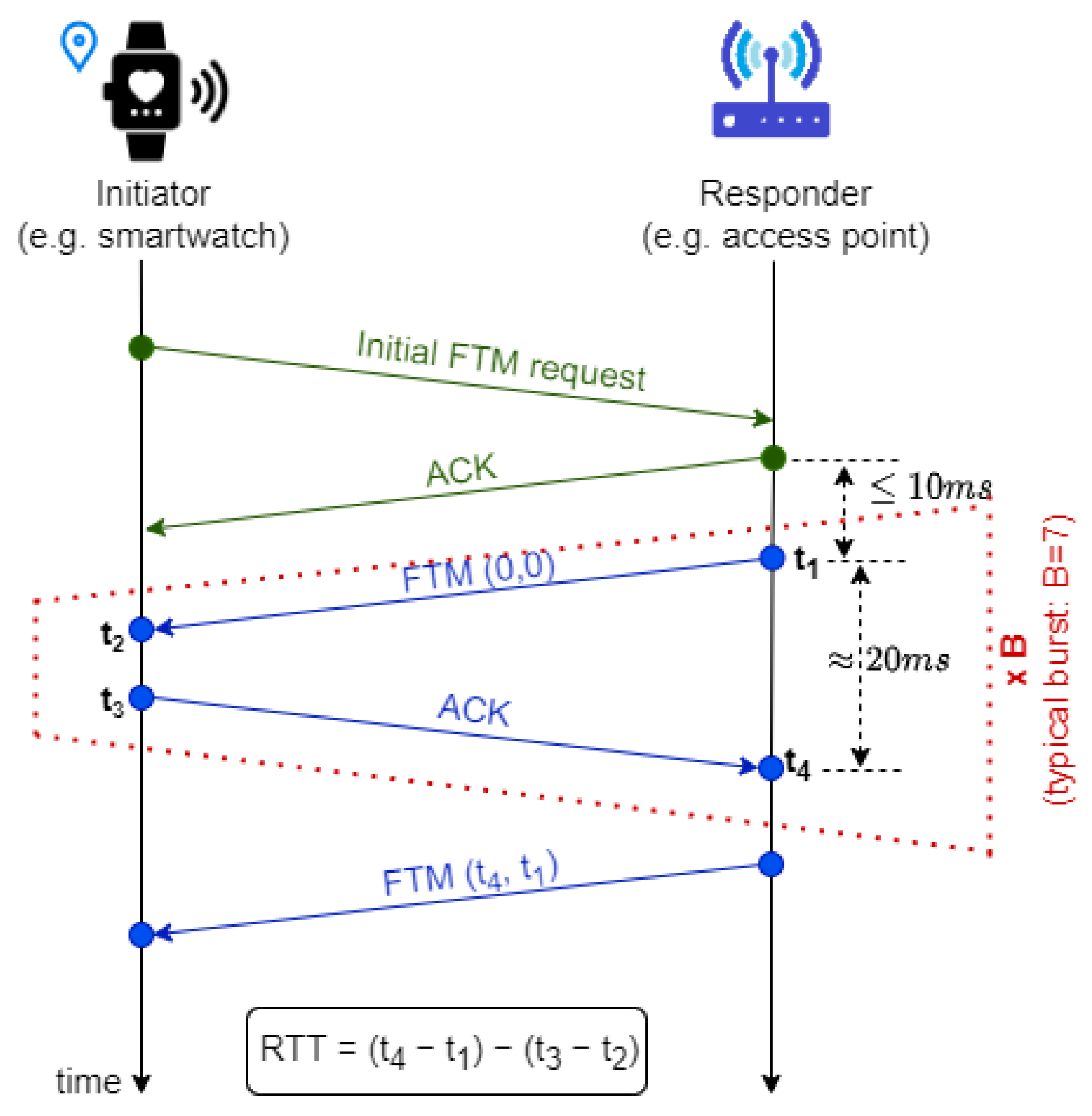
7] that enables precise distance measurements based on the round trip time (RTT) of Wi-Fi signals. The IEEE 802.11mc protocol, popularly known as Wi-Fi RTT, involves two Wi-Fi stations (STAs). As illustrated in
Figure 1, an STA seeking to determine its position, referred to as the initiator (e.g., a smartwatch or smartphone), transmits a request to another STA, known as the responder (e.g., an AP).
This initial request establishes the required parameters for the responder to transmit FTM messages. Each FTM message is confirmed by the initiator via an acknowledment (ACK) frame. Both STAs record the timestamps associated with each frame exchange:
To enable distance estimation, the responder includes its timestamps (, ) in a subsequent FTM frame sent to the initiator. The initiator then computes the RTT by subtracting the processing delay at the initiator () from the total round-trip time observed at the responder ().
It is important to highlight that the time interval (
) is difficult to predict and typically exhibits values several orders of magnitude larger than the signal time of flights (TOFs) (e.g., (
) and (
)). However, these TOFs directly correspond to the distance between the two STAs; therefore, they are the key values that must be estimated accurately. In this regard, the IEEE 802.11mc standard ensures that, throughout the FTM process, these timestamps are recorded with nanosecond precision on both STAs. Additionally, the number of FTM-ACK sequences, known as the burst size (
B), can be negotiated in the initial FTM request, which is sent in the clear. This procedure enables the averaging of the individual RTT in the burst size, thus fostering more reliable RTT estimations [
15]. Typically, the burst size is set to 7, meaning that the responder transmits a total of 8 FTM messages. The initiator needs to perform the RTT procedure with several APs to determine its own position (e.g., at least three APs for a 2D position).
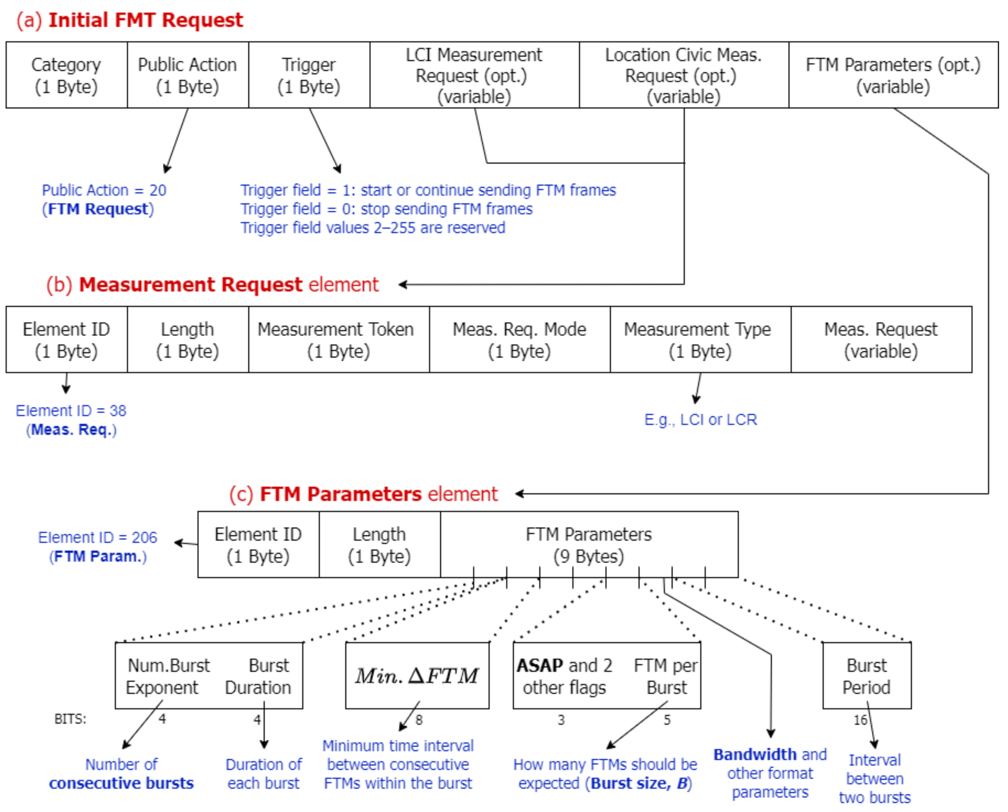
Localization while minimizing both bandwidth consumption and latency is of capital importance in the IEEE 802.11mc standard. For this reason, the FTM mechanism was designed so that it can start without the need for previous association between the initiator and responder (hereafter referred to as the AP), and therefore, no authentication with the AP is required, and no cryptographic material is negotiated with it. Thus, all frames are exchanged in the clear (not encrypted), and data confidentiality and integrity are not provided. The initial FTM request allows for the configuration of key localization parameters, including the number of consecutive bursts, the burst size
B, the time interval between consecutive measurements, and the bandwidth.
Figure 2 depicts the format of the FTM frame defined in [
7], with the main parameters negotiated in the FTM Parameters element. Additionally, the initiator can use the initial FTM request to ask for the Location Configuration Information (LCI) and Location Civic Report (LCR) parameters by including a Measurement Request element (see
Figure 2b) with the Measurement Type field equal to LCI or LCR, respectively. These parameters contain the coordinates and orientation of the AP and enable the initiator to refine its own position estimation.
Both the initial and subsequent requests contain two special fields: (1)
trigger (see
Figure 2a), which indicates whether the FTM session should start, continue, or terminate; and (2)
ASAP (see
Figure 2c), which specifies whether the session should begin immediately (ASAP = 1) or be scheduled to start within a specific time window (ASAP = 0). On top of that, each response sent by the AP includes a
token field (Measurement token in
Figure 2b) that allows the initiator to correlate responses with the corresponding ACKs. The token is a nonzero integer that increments with each response. The last response in a burst must have a token value of zero, indicating that no further measurements will be taken in that burst.
Besides the lack of security mechanisms, the FTM procedure exhibits other vulnerabilities, both because of its design and the implementation of the protocol in a specific STA [
11,
14]. In the following, we give an overview of such vulnerabilities and the attacks against the FTM procedure that have been described in the literature so far. To the best of the authors’ knowledge, the number of works covering the attacks over Wi-Fi RTT positioning [
11,
14,
16,
17] is rather limited.
2.1. Data Injection
Since AP authentication is not required for the FTM procedure, an attacker could easily set up a rogue AP and establish an FTM session with an initiating STA. Once the procedure has commenced, the rogue AP may transmit responses with falsified
and
measurements, and as the initiator cannot verify the authenticity or the integrity of the received data, such measurements might mislead the STA into an incorrect estimation of its position. In [
14], several implementations were tested, revealing that most STAs accept any value without further verification. Some implementations may analyze the plausibility of the measurement and filter out values exceeding a predetermined threshold. Furthermore, if the rogue AP introduces a significant bias in the reported measurement, it may prevent the positioning algorithm from converging, rendering the STA’s location estimation infeasible and leading to a Denial of Service (DoS) attack.
Another attack with similar consequences involves forging LCI data. An initiator can request an AP’s LCI, which consists of the AP’s geographical coordinates for localization purposes [
18]. As highlighted in [
14], forging LCI parameters is relatively simple from a practical standpoint, as it only requires modifying a file (on Linux systems). In contrast, timestamps are computed by the Digital Signal Processor (DSP) chip, which requires a higher level of control over the operating system to manipulate them.
When AP authentication is absent, an attacker may also inject false data into an existing FTM session between an initiator and a legitimate AP [
11,
16]. The initiator will accept these data if the attacker successfully spoofs the MAC address of the legitimate AP and transmits an FTM response frame with a valid token field. The token is a nonzero value included in a response frame, enabling the correlation of each response with the corresponding ACK returned by the initiator. It increments by one with each response, and the final response must include a zero token, indicating that no further measurements will be performed within the burst. Since FTM frames are not encrypted, an attacker can easily obtain the AP’s MAC address and the last token used in the session by eavesdropping on the communication channel.
2.2. Replay Attacks
The IEEE 802.11mc standard does not include mechanisms to prevent data replay and provide freshness, i.e., to ensure that the received information is “fresh” and does not belong to an old session. Consequently, if tokens are not generated in a secure way (e.g., the initial token always has the same value), an attacker could easily eavesdrop on an active FTM session, capture FTM frames, and retransmit them in a subsequent session. This allows the attacker to provide incorrect measurements to an initiator without the need to forge response frames [
16].
2.3. Denial of Service (DoS)
As discussed in
Section 2.1, an adversary can execute a DoS attack by injecting false data to make the location service unavailable. Erroneous measurements may disrupt the localization process to the extent that the initiator is prevented from estimating its position. However, DoS attacks can also be executed through other methods. For instance, an attacker may forge a response frame with the token field set to zero, prematurely terminating the FTM burst before all required measurements are completed [
11].
APs support a limited number of concurrent FTM sessions, which varies based on manufacturer and device version. For example, the firmware versions of the Intel AX-200 and AX-210, used in [
11], support up to 10 concurrent sessions, whereas earlier versions accommodate up to 32. Once this limit is reached, the AP rejects further FTM session requests. An attacker could exploit this limitation by initiating FTM procedures from multiple devices, thereby preventing STAs from obtaining their location.
2.4. Location Leakage of Initiating Stations
Since all the frames exchanged in an FTM session are transmitted in the clear, thus lacking data confidentiality, an adversary can eavesdrop on an ongoing FTM session and capture the and measurements reported by the AP. Under the assumption that (1) the initiator uses a fixed MAC address and (2) sufficient measurements from different APs are eavesdropped, an attacker might be able to estimate the initiator’s position.
To mitigate location information leakage, the passive TDOA technique proposed in [
19] can be employed. This method enables a passive STA to determine its position by observing FTM measurements exchanged between an initiator and multiple APs (at least three). In [
11], the authors extended this approach by proposing a hyperbolic solution for joint positioning; they conducted real-world experiments, demonstrating meter-level accuracy in position estimation. While these experiments focused on a simplified scenario where the passive STA is positioned between the initiator and the AP (i.e., along the transverse axis of the hyperbola), they provide valuable insights into the accuracy of passive self-positioning methods.
In this paper, we go a step further; we demonstrate that passive TDOA can also be exploited by an attacker, acting as a passive STA, to infer the position of an initiator, whatever the position of the attacker.
2.5. MAC Address Randomization Flaws
MAC addresses are unique identifiers, and therefore, they can be used to track users when transmitting data, thus violating their privacy. A common countermeasure is MAC address randomization, as recommended by the IEEE 802.11mc standard. However, the standard does not specify precise guidelines for performing randomization.
Many modern devices (e.g., Android smartphones) implement specific mechanisms to generate random MAC addresses for each new FTM session. However, some implementations (such as older Intel network cards) are insecure due to predictable randomization algorithms that generate the same sequence of addresses after a firmware reset [
11]. Additionally, previous works such [
11,
20] show that frame correlation under MAC randomization is feasible by performing side-channel attacks based on power measurements or sequence numbers.
2.6. Security Mechanisms in IEEE 802.11az
The IEEE 802.11az amendment for Enhancements for Positioning [
13], released in 2023, aims to improve Wi-Fi FTM security. Notably, it introduces the so-called Pre-Association Security Negotiation (PASN), which enables an initiator to establish a secure session with an AP without requiring association, thereby protecting the FTM procedure from unauthorized observers. Through PASN, the initiator and AP agree on Pairwise Transient Key Security Association (PTKSA) and encryption/authentication algorithms (e.g., Advanced Encryption Standard (AES) in Counter with CBC-MAC mode (CCM), or Galois/Counter Mode (GCM)) to secure frame exchanges.
PASN can operate with or without AP authentication. In the authenticated mode, the initiator and the AP must share a pre-shared key (PSK) in advance, which is feasible in private networks but impractical in public venues [
14]. In the unauthenticated mode, FTM messages are protected via encryption and integrity mechanisms, but PASN does not prevent attackers from establishing rogue FTM sessions and injecting false data. In [
9], the authors propose a mechanism to select APs for the FTM procedure so that the probability of choosing rogue APs is minimized.
IEEE 802.11az also introduces the Secure Long Training Field (LTF), which enhances range estimation security using AES-128 pseudorandom sequences. This countermeasure is mainly targeted to secure proximity technologies, such as Near Field Communication (NFC), which can be vulnerable to Man In the Middle (MiTM) attacks or Time Advanced attacks.
Additionally, in order to prevent replay attacks, encrypted frames incorporate a Packet Number (PN), a field that is incremented with each transmission and authenticated by means of the authentication algorithm negotiated during the PASN.
Although these mechanisms address many security concerns in Wi-Fi RTT, their widespread adoption in COTS devices remains uncertain in the short term. Consequently, understanding the security vulnerabilities of IEEE 802.11mc and implementing appropriate countermeasures still remains critical.
3. Position Estimation by Eavesdropping on an FTM Session
This section describes a method that allows an attacker to infer the position of an STA (the victim, hereafter) by eavesdropping on the FTM procedure performed between the victim and a given number of APs. The method relies on the Wi-Fi passive TDOA algorithm presented in [
19], in which a STA passively estimates its own position based on the FTM exchanges initiated by others. In this work, we turn the problem around and show that an attacker (
A) can act as the passive station and take advantage of the above-mentioned algorithm.
We assume a Dolev–Yao model [
21] for
A, i.e., it is capable of eavesdropping on, intercepting, and forging any message, and it is only limited by the cryptographic methods used by the victim. Since IEEE 802.11mc control frames are transmitted in the clear, it is straightforward for an attacker to read the content of the FTM messages in the considered scenario. Also, another assumption is that the attacker is carrying out the attack with a laptop or a COTS device without significant constraints on CPU or memory resources.
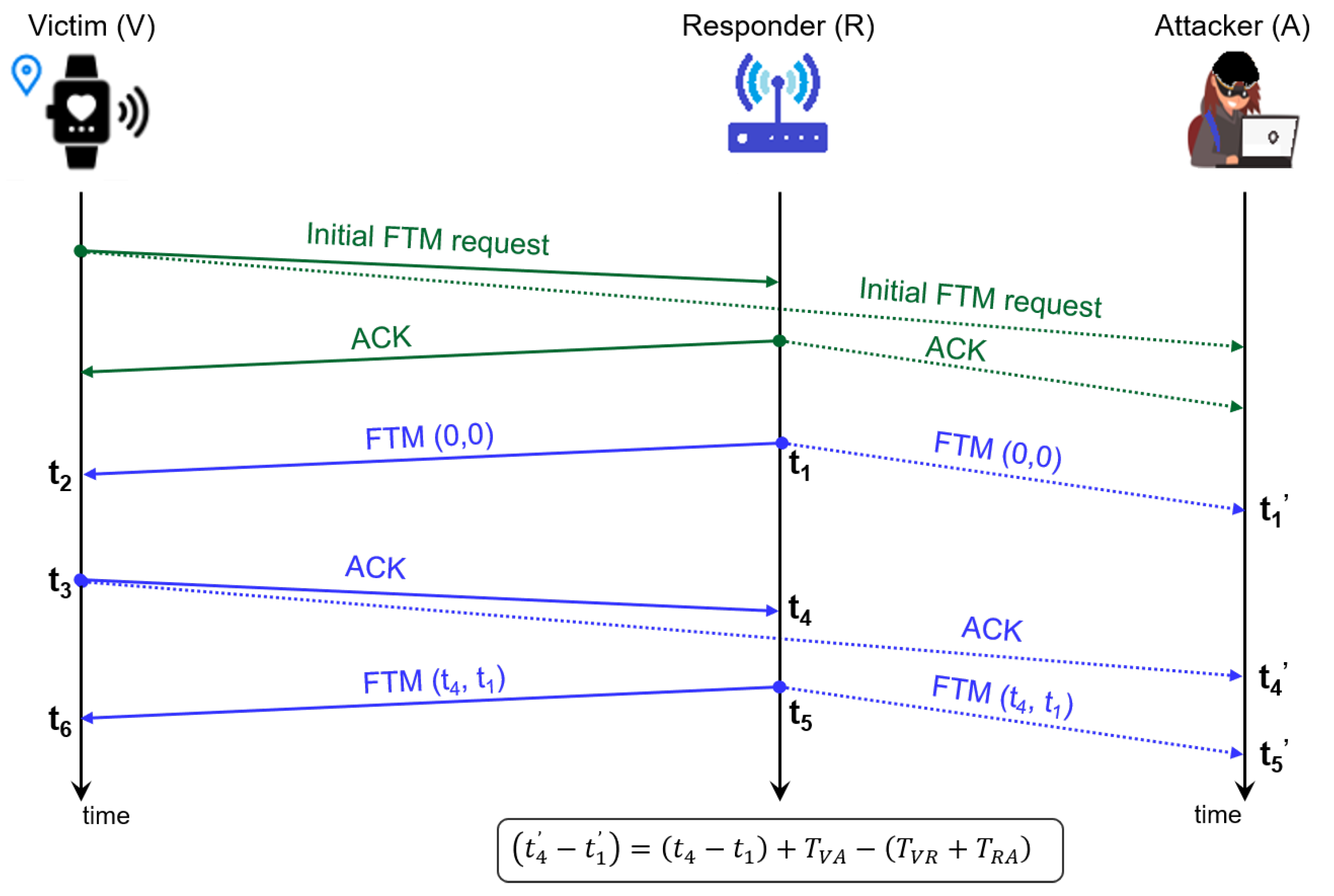
Figure 3 depicts how the proposed attack works. The victim (
V) initiates an FTM procedure by sending an FTM request that will be answered with an ACK by an AP (the responder (
R) in our formulation). Then, an FTM frame and an ACK are sent so the timestamp of the former (
) and the time of arrival (TOA) of the latter (
) can be recorded at
R, and reported back to the victim in the following frame
.
V can compute a precise RTT from Equation (
1):
where
is the TOF from station
i to station
j, and
is the time between the reception of an FTM at
V until the corresponding ACK frame is sent (i.e.,
).
Due to the broadcast nature of the Wi-Fi medium, the frames exchanged between
V and
R will reach the attacker (
A) as well. Hence,
A also knows
and
. In addition,
A can set a precise measurement for the TOA of the FTM and ACK frames, leading to timestamps
and
, and calculate the TDOA as follows:
where
involves the path from
R to
A and
the path from
R to
V and then from there to
A.
As demonstrated in [
19], by combining Equations (
1) and (
2) and assuming TOF measurements to be equal in both directions (
), Equation (
2) can be rewritten as:
Note that delta, which is unknown to the attacker, is then removed from the equation [
19].
A single TDOA measurement
defines a hyperbola of possible positions. In order to infer the position of the victim, the attacker needs to eavesdrop on several FTM sessions between
V and different APs, and compute the corresponding TDOA measurements. From each measurement, an equation like Equation (
3) can be derived, and time measurements can be turned into distances by multiplying both sides of the equations by
c, the speed of light. As a result, Equation (
3) can be rewritten as:
where
is the Euclidean distance between devices
i and
j, i.e.,
. Equation (
4) defines the TDOA distance (
from now on).
Section 4.3 shows how to build an equation system suitable for use with a multilateration algorithm.
4. Methodology
Currently, the restrictions imposed by vendors on their hardware make it difficult (if not impossible) to deploy a testbed and run the proposed attack with Wi-Fi COTS devices. On the one hand, the monitor mode must be enabled in the attacker’s Wi-Fi card, so that it can process the Wi-Fi management frames exchanged by other peers (i.e., FTM frames between the initiator and the APs). However, changing the 802.11 capture mode depends on the platform/network adapter/driver/libpcap [
11]; moreover, the evaluation may be biased by the specific hardware used in the experiment, thus requiring complete deployment on several devices to obtain a realistic and generic performance estimation, as also observed in [
19]. On the other hand, the attacker’s Wi-Fi card must enable fine timing measurement, which is necessary so that the attacker can store the timestamps (
,
, and
in
Figure 3) with nanosecond precision; however, it is not clear whether it is possible when the initial FTM request is addressed to the initiator and not to the attacker. For these reasons, the positioning error analysis proposed in this paper was conducted through simulations in Python [
22]. First, the simulation layout and parameters are described in
Section 4.1. Moreover, two scenarios are considered: one named “Ideal”, where the possible errors that may incur when measuring the TDOA are considered to be negligible; the other one named “Real”, where an error is added to the TDOA estimations made by the attacker (
A). The error model used in this study is described in
Section 4.2, while the algorithm used to translate the TDOAs into a position is presented in
Section 4.3.
4.1. Scenario and Simulations
A squared area of side 16 m is considered, with four APs providing Wi-Fi coverage. The APs will be located near the corners at positions (
,
) (see
Table 1), following the recommendations from Aruba [
23], which suggests that the “distance between two APs should be approximately 40 to 60 feet”. For the victim’s (
V) positions (
,
), a grid of 1 m side is defined, and
V can only be placed in one of the points in the grid. Several layouts are considered, where
A and/or the APs can take different assets.
In layout 1, the attacker (A) is placed in one of the points in the grid (, ). Since the APs are placed near the corners but not in the points of the grid, neither A and/or V can overlap with them. This first layout is highly symmetrical, as the purpose is to observe whether and how the geometry may affect the precision of the position estimation in the first place. Then, a second layout (layout 2) is considered, where A is located randomly in the scenario, while leaving the other settings as in layout 1. In order to provide statistically relevant results, 500 random positions are considered.
In the first place, an ideal scenario is considered, where all the TDOA estimations can be easily translated into distances by multiplying them by the speed of light. This ideal scenario is investigated for layouts 1 and 2. However, a more realistic scenario is also considered, where an error is added to the TDOA estimation, as described in
Section 4.2.
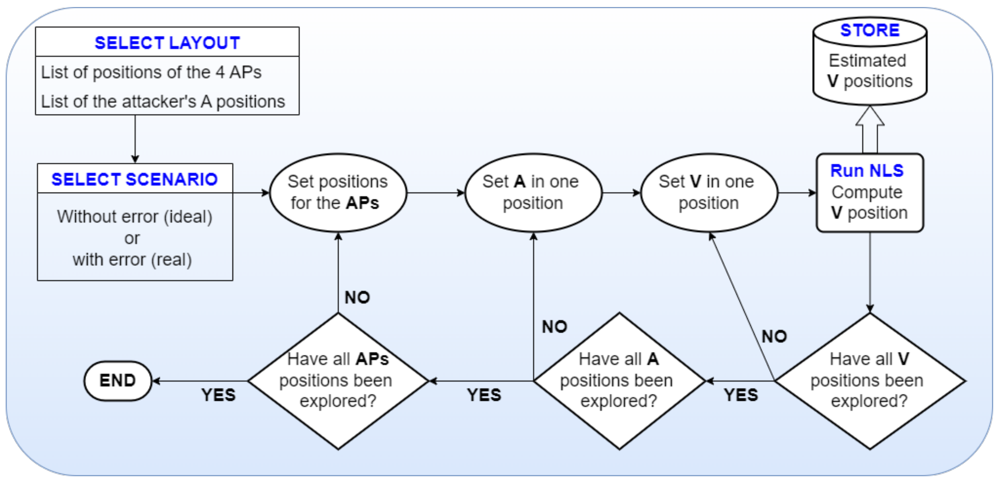
The methodology followed in this paper is summarized in
Figure 4. For each layout and scenario, the simulation starts with
V placed in the first position of the grid (e.g., (0, 0)), and
A in the first position according to the selected layout (e.g., (0, 0) in layout 1, or in the first of the 500 random positions in layout 2); the position of
V is estimated according to the procedure explained in
Section 4.3. Then,
A is moved to another position depending on the layout, and the position of
V is estimated again. Once all the possible positions of
A in the layout are considered, then
V is moved to the second position (e.g., (0, 1)), and again
A repeatedly moves through all the points defined in the selected layout. This is repeated again, until
V is placed in the last possible position of the grid (e.g., (16, 16)).
Before providing the details on how the position of the victim is estimated, the error model used in the realistic scenario is described in
Section 4.2.
4.2. Error Estimation
Equation (
4) defines the TDOA measurement performed at the attacker in an ideal scenario with no errors. Under the presence of errors, Equation (
4) can be rewritten as follows:
where
can be computed as the error in the TDOA measurement
minus the error in the rough RTT measurement
. As in [
19], measurement errors are modeled as additive noise to the TOF values used to compute both the RTT and the TDOA measurements considered in
Figure 3. Such errors mainly depend on the hardware used and the propagation model; in indoor environments, signals are prone to be affected by multipath or degraded due to propagation and obstacles [
24]. According to the experimental studies conducted in line of sight (LOS) conditions in [
19], the TOF measurement error can be modeled as a zero-mean Gaussian distribution, with a distance-dependent standard deviation as in Equation (
6):
where
is the reference standard deviation, and
d is the distance between the two devices involved in the TOF measurement.
While the assumption of LOS conditions is common, it does not always hold in real-world scenarios. A study in [
25] found that Wi-Fi TOF ranging estimates, taken at 5 GHz with an 80 MHz bandwidth, remain unaffected by non-line of sight conditions at distances of up to 20 m. However, according to the authors, beyond this range, increasing the density of APs can enhance the reliability of distance measurements. In this study, we adopted the error model presented in Equation (
6), leaving the impact of additional complexities, such as non line of sight (NLOS) conditions, for future research.
4.3. Position Estimation
According to the methodology summarized in
Figure 4, the position of the victim
V can be estimated once the position of the APs and of the attacker
A are set. Thus, the following parameters are considered to be known:
The attacker’s position (, );
The position of k APs (,);
The timestamps at which the FTM is sent by each AP (i.e., , , etc.);
The timestamps at which the FTM, sent by each AP, is received at A (i.e., , , etc.);
The timestamps at which the ACK, sent by V, is received at each AP (i.e., );
The timestamps at which the ACK, sent by V to each AP, is received at A (i.e., ).
Note that according to these assumptions, the coordinates of
V are the only unknowns in Equation (
5). Thus, at least three TDOA measurements will be needed (two of them to determine the victim’s coordinates, and an additional measurement to avoid the quadratic ambiguity), leading to a system of three hyperbolic equations with two unknowns.
As reported in [
26], a Least Squares (LS) algorithm is typically used for positioning. We adapt Equation (
1) in [
26] for our situation, where the estimated distance is the TDOA distance instead. From the estimated distances
derived from each measurement (i.e., Equation (
5)) and known positions (
,
) and (
,
) of each
k AP and
A, respectively, the position (
,
) of the victim can be calculated by finding (
,
) that satisfy:
The least_squares SciPy function [
27] was used in this work to solve the system of quadratic equations; this function requires an Initial Guess (IG) (i.e., (
,
)) for the position of the victim as input. Typically, as the positions of the APs are known, the IG is set as the centroid among them. Also, the solution space was bounded in this study, considering the nature of the Wi-Fi signal that imposes a maximum distance for
A to be able to eavesdrop on the FTM frames between
V and the APs. While the distances between
A and each AP are bounded by the simulation area itself, the estimated
V position can be searched out of it, provided it is not too far away from
A (i.e., in order to guarantee the Wi-Fi signal is received correctly at A). Thus, the search space for
and
is limited to a maximum distance from
and
, respectively, equal to the maximum distance allowed in the simulation area, i.e., 16
m. The default tolerance for the termination of the iterative search process in Python was used in this work (i.e., 10
−8). While tuning this parameter may lead to more precise estimations, it is out of the scope of this work and it is left for future work in the first place.
6. Conclusions
The Wi-Fi positioning method based on the exchange of FTM frames between peers has been recently made available in Android devices by Google. However, since the initial FTM request can be sent without the need for previous authentication, the method is prone to several vulnerabilities. On top of that, the FTM measurements are sent in the clear, paving the way for an intruder to eavesdrop on this information.
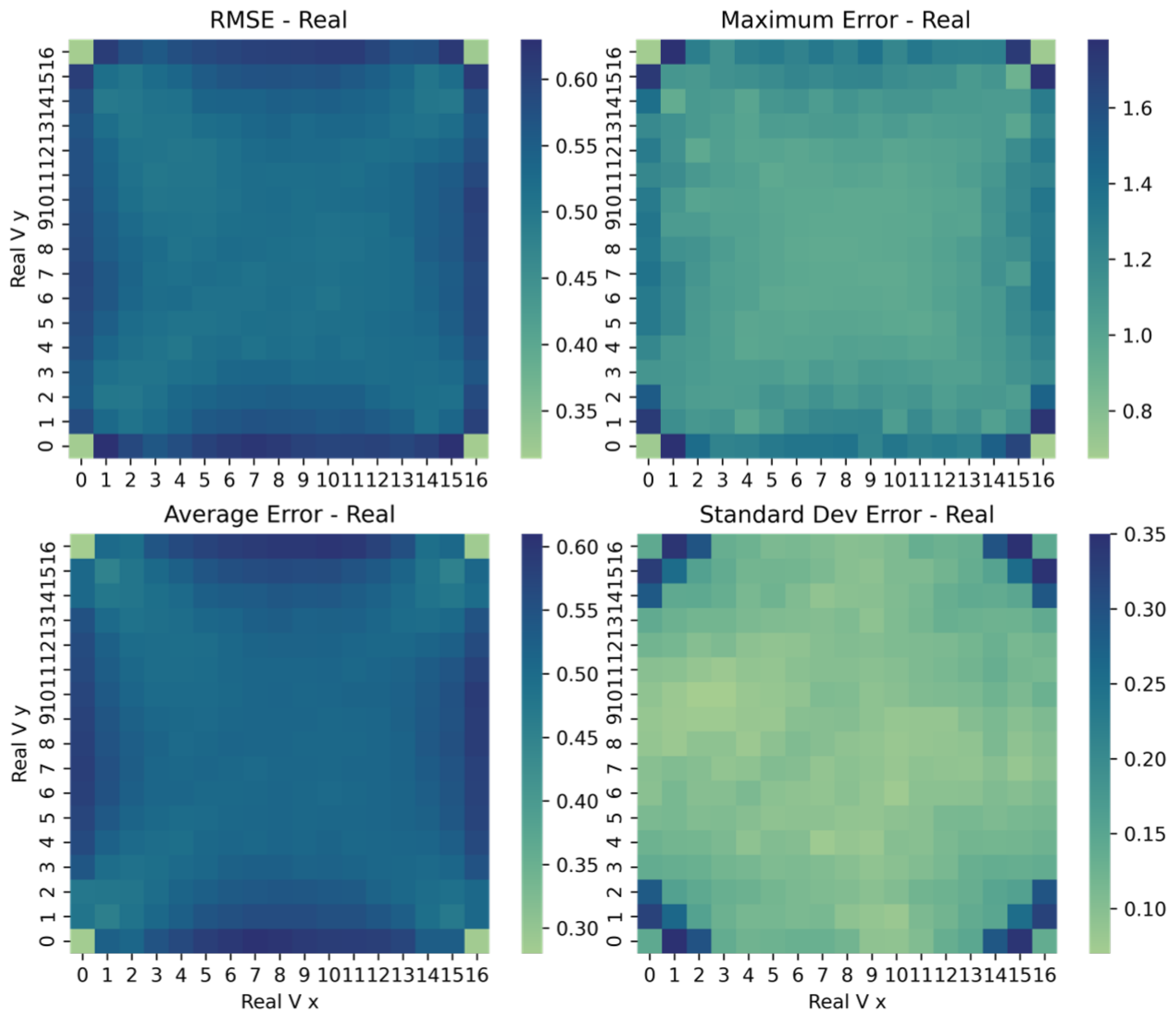
In this paper, we are interested in assessing to what extent this information is sensible. Is it just a matter of “someone else has my own FTM messages” or may the intruder determine my position by means of such information? And if so, how precise can its estimation be? To this end, a number of simulations were conducted with Python, which prove the feasibility of the attack. A squared room with four APs was considered, located at the corners at a distance of 16 m up to 22.6 m between each other; the latter is also the maximum distance between the victim and the attacker. In the first place, an ideal scenario was considered in order to estimate the highest precision that can be obtained with the multilateration algorithm. Under the assumption of no measurement errors and with the default tolerance for the termination of the search method, the RMSE ranges from 9 mm to 27 cm, depending on the layout considered. Also, the symmetrical layout sheds lights on the precision drop under particular GDoP conditions.
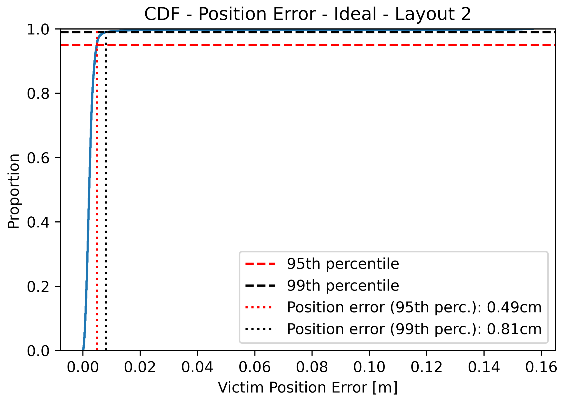
Under more realistic conditions, i.e., with noisy RTT measurements and with randomly located devices, simulation results show that the position error is lower than 1 m in 99% of the cases, with an RMSE of 54 cm. These preliminary results highlight the fact that FTM-based location represents a serious threat to the privacy of users and pose the need for immediate solutions until COTS devices support IEEE 802.11az.
A potential countermeasure to the attack described in this paper could be to set a dedicated node in the network infrastructure to act as an active station so that regular users can passively obtain their position [
19], i.e., without the need of sending any frames, thus without disclosing location information. However, this approach can be vulnerable to other attacks, such as the impersonation of the dedicated node. In the future, we aim to assess the precision of the attack when the malicious node has no knowledge of its own position.


