Abstract
In modern electronic reconnaissance systems, digital receivers play an important role in receiving a variety of complex signals, in which signal-to-time extraction is a key issue, but traditional methods often rely on the signal envelope, which is easily affected by the value of the threshold setting and the signal-to-noise ratio (SNR) of the signal. In fact, the pulse envelope front has a large derivative, which leads the envelope differentiation to show sharp peaks. In this paper, a time of arrival (TOA) extraction method based on first-order envelope differentiation of the signal is proposed. The method realizes the normalized extraction of different modulated signals by estimating the location where the sharp peaks appear, and it is not easily affected by the threshold setting. The processing flow of the digital receiver is as follows: the signal is first processed by digital channelization, and, after channelization, it passes through the signal detection module; then, after envelope differentiation, the useful signal is filtered out according to the result, and, finally, the pulse descriptor word consisting of the pulse arrival time, pulse width, signal frequency, and signal amplitude is formed, which is convenient for the subsequent processing. The experimental results verify the effectiveness and reliability of the signal arrival time extraction method.
1. Introduction
Broadband reconnaissance receivers play a pivotal role in electronic countermeasures. With the high-speed development of digital signal-processing technology and the corresponding device level, the digital reconnaissance receiver has received more and more widespread attention because of its small amount of equipment, flexible algorithms, ease of expanding the function, and other advantages. On the modern battlefield, the signal environment is dense and complex [1], and the digital receiver needs to receive a variety of radar signals with complex wavelength durations and possible in-pulse modulation [2]. Moreover, the amplitude and the dual-tone instantaneous dynamic range of different signals vary greatly [3,4,5]. Collectively, these requirements impose more stringent demands on the sensitivity, instantaneous dual-tone dynamic detection range, and accuracy of TOA. In particular, signal TOA detection assumes a critical role. Within the wideband digital receiver framework, this paper proposes a method focused on improving the accuracy and reliability of TOA detection. Meanwhile, the instantaneous bandwidth of narrowband radar signals is generally in the order of a few MHz, and the instantaneous bandwidth of ultra-wideband radar signals is several hundred MHz or even higher than 1 GHz. Specialized in spectrum signal reception, this solution is widely utilized in spectrum-sensing domains [6]. Therefore, the broadband reconnaissance receiver also necessitates higher requirements, and the receiver is usually required to cover at least the instantaneous bandwidth of the radar signals in order to obtain the complete signal spectrum information. Existing digital signal processors have the ability to process narrowband radar signals in the microsecond order of time, but cannot directly process the sampling rate of the high-speed data in the GHz class. The receiver front-end uses high-speed A/D conversion in order to accomplish wideband instantaneous coverage, and multiplexers are used to expand the GHz-scale data stream into a low-speed data stream that can be accepted and processed by the digital signal processor. One of the practical ways to implement wideband digital receivers using modern technology is through channelization techniques. A digital channelized receiver is an ideal choice; it can handle multiple signals arriving at the same time with high interception probability and is especially suitable for applications in a wideband radar countermeasure reconnaissance receiver, which applies the principle of a channelized receiver to the digital receiver [7] combined with flexible digital signal-processing technology, which can satisfy the engineering requirements relatively well.
Engineering digital channelized receivers generally use the time domain and frequency domain in two ways [8]: the time domain involves the construction of a digital filter bank to complete the channelization, while the frequency domain is achieved using the addition of window FFT, based on the time-domain multiphase filter bank of digital channelization technology. The advantage lies in the fact that the adjacent channel amplitude is small, and the sub-band suppression system is high, so this paper adopts the multiphase filter structure of digital channelization. The digital channelization receiver uses a digital filter bank to split the instantaneous bandwidth coverage into many sub-bands; each sub-band is called a channel [9]. Then, the output of each channel is detected and measured, and, finally, the signal analysis results of the corresponding channel, such as carrier frequency, arrival time, and pulse width, are obtained by threshold discrimination. The basic principle of digital channelized receivers is similar to that of analog channelized receivers, and it is usually considered that a single channel covers a single signal bandwidth, and there is only one signal arriving in the same channel at the same time.
Signal TOA estimation is an important step in electronic reconnaissance, generally detecting the channel data after channelization. Radar signal TOA detection is a prerequisite for signal pulse width estimation, repetition frequency estimation, and other important steps. The above parameters are widely used in radar source identification, direction finding and positioning, and other important areas, so the TOA detection and estimation of radar signals has been an important research topic [10].
The traditional TOA detection method uses the adaptive threshold method [11,12] and correlation convolution method [13,14,15]. Such algorithms need to extract the pulse envelope information, affected by the threshold setting and high requirements for SNR; there is also a time frequency method [16,17,18,19], which uses time frequency means, such as wavelet transform. Although this class of algorithms has a high estimation accuracy, the computational complexity is large, to the degree that it is difficult to realize in the field of engineering, and many scholars have now proposed TOA extraction methods based on deep learning [20,21,22], but they are also not easy to implement in engineering.
In this paper, on the basis of the above research, an improved digital receiver based on envelope differentiation is proposed, where the basic idea is to perform digital channelization of the signal, obtain the data of multiple channels, then perform envelope differentiation of the channel data, extract the signal TOA according to the results of the processing of each channel, and finally, generate the pulse description word. The experimental results verify the reliability and accuracy of the method.
The rest of this paper is organized as follows. Section 2 proposes the new methodology, which includes processing of the digital channelization and envelope differentiation. Section 3 describes the experimental setup that is used to demonstrate the proposed methods with envelope differentiation and presents the experimental results. Section 4 provides discussions, and Section 5 concludes the paper.
2. Methodology
2.1. Digital Channelization Based on Multiphase Filter Banks
Digital channelization is the process of performing uniform channel division and extraction of a broadband signal in the frequency domain and finally outputting a number of low-speed baseband signals. Its functionally equivalent is to divide the signal to be detected into a uniform number of sub-bands using an FIR filter bank with an extractor. In general, if the FIR filter is , its Z-transform can be given by
where N is the filter order. The FIR filter arrangement is divided into M groups, where M is the number of channels, and N is set to be an integer multiple of M, N/M = Q, with Q being an integer. The filter polyphase can be written as
Similarly, the received signal can be divided into M groups, and the structure of the efficient multiphase filtering implementation is shown in Figure 1.
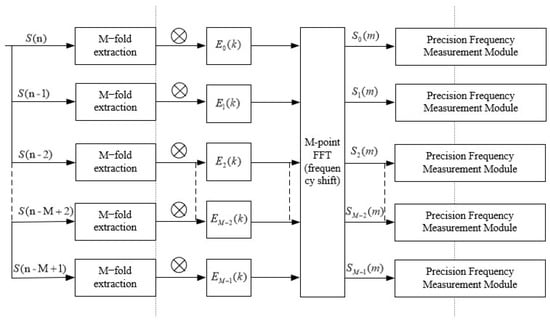
Figure 1.
Block diagram of digital channelization process for multiphase filtering structure.
The original signal in Figure 1 is transformed into M channel signals after delayed extraction, and the length of each road signal is N. These signals are then convolved with the filter multiphase structure in Equation (2) to generate M road filtered outputs, and the radar signals are intercepted by the receiver after efficient multiphase filtering implementation, shown in Figure 1, which will output a number of roads with zero intermediate-frequency signals. Detection for each road signal can form a pulse descriptor word consisting of the TOA of the pulse, pulse width, and pulse description, which is a word composed of the pulse arrival time, pulse width, signal frequency (represented by the channel number), signal amplitude, etc. This method is very conducive to engineering realization because the down-conversion and filtering are carried out after data extraction; meanwhile, the data rate is greatly reduced, which improves the system operational efficiency.
2.2. The Method for Detecting TOA Based on Envelope Differentiation
Radar signal TOA detection is generally processed after channelization, and based on the channelization envelope results, an adaptive threshold is used to detect the leading edge of the TOA to overcome the effects of pulse undulations, as shown in Figure 2.
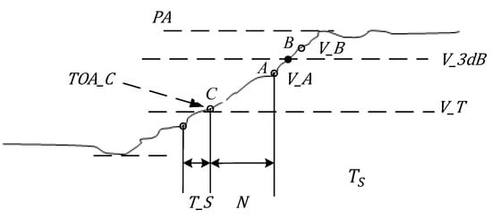
Figure 2.
Conventional TOA measurement method.
In Figure 2, is the detection threshold, which is used to control whether the output sampling point of the A/D is latched or not and is generally taken as , with as the receiver noise level.
Two points around the −3 dB threshold are usually used to fit the leading and trailing edges to make the TOA measurement results more robust. In the following formula calculation, will be used instead of the TOA. First, we calculate the measured value of pulse amplitude , find the two points A () and B () near the −3 dB threshold, and determine the true by the intersection of their lines with the −3 dB threshold. We calculate the time offset between the intersection point and point A, and then we add the time of point A as the true . The can be calculated as
where N is the number of sampling intervals between A and , , and is the sampling clock period.
The setting of the adaptive threshold requires that the amplitude of the pulse be measured first, but the measurement of the pulse amplitude is unstable and unreliable as the actual signal may have an irregular envelope shape after detection. For example, the envelope of a Linear Frequency Modulation (LFM) or a narrow pulse is usually rounded at the top of the pulse, and the coded signals have “notches” between code elements due to the imbalance of the amplitude–frequency characteristics of the filters in the receiver. In addition, the pulse envelope is also subject to overshoot artifacts, which cause unstable undulations at the top of the envelope. All these can cause the to be measured incorrectly, which in turn affects the measurement accuracy of the TOA. On the other hand, the traditional method of TOA measurement needs to be carried out after the completion of the measurement, so it must require the design of a certain holding circuit to cache the rising edge data of the pulse, which leads to the delay of the TOA measurement being significantly longer than the other parameters of the pulse. For this reason, a corresponding synchronization mechanism has to be designed, which increases the complexity of the hardware implementation. On the basis of the above research, this paper proposes a TOA measurement method based on envelope differentiation to estimate the arrival time of the pulse front by searching for the peak of the signal envelope and interpolating it. While envelope differentiation has previously been utilized in low-power wireless devices [23] and communication signal demodulation [24], this paper presents its application to radar TOA detection. The basic principle is that the pulse envelope front has a large derivative, so the envelope differentiation data show a sharp peak on the pulse front. Estimating the location where this peak occurs gives an estimate of the pulse frontier time. The method does not require pre-estimation of the parameters, and the peak detection directly uses the results of the pulse detection, after which the TOA measurement can be performed.
Assuming that the moment of appearance of the peak of the envelope of the output signal at the channel is N, the true is modeled as (N − ) where denotes the fractional sampling offset. Using the derivative values at , based on linear signal characteristics, the equation can be written as
Substituting Δ into the time expression yields the estimate:
where is the sampling clock period, and is the sequence after first-order envelope differentiation of .
In order to adapt to the lower SNR, the least squares method is used for differentiating the envelope after digital channelization, and the envelope slope is calculated by fitting with multi-point data. The calculation process is described in detail below.
The signal within a symmetric window around sampling point is approximated by a quadratic polynomial:
where is the central sampling time. The least squares objective function is constructed to minimize the sum of squared residuals between the sampled signal values and the polynomial model:
We take partial derivatives with respect to and set them to zero. Using the symmetry property and , since is an even function we have , and the equation simplifies to
According to the second formula in the set numbered (8), from the equation of , substitute the expression for :
The final simplification can be written as
In the discrete sampling context, we focus on the instant , corresponding to the sampling point . Substituting into the derivative formula:
Thus, (specifically, the first-order derivative of the signal at point k) is precisely equivalent to the polynomial coefficient .
This formulation balances noise suppression and computational efficiency, providing a robust estimate of the signal’s local slope. Equation (6) is used to accurately estimate the , leveraging sample interpolation to go beyond sampling resolution limits. Yet, its reliability diminishes under noise interference or non-smooth signal changes (e.g., multipath impacts). Meanwhile, Equation (13) is primarily designed for signal smoothing and noise suppression. However, the selection of the window parameter (e.g., N) is critically important. An excessively small parameter value leads to insufficient noise reduction, while an overly large one easily distorts signal features. Moreover, it increases the computational load, thereby affecting the efficiency of real-time processing.
2.3. Improved Digital Receiver Design Based on Envelope Differentiation
The radar signal intercepted by the receiver will output a number of zero intermediate-frequency signals after the multiphase filtering process, and the signal detection for each signal can form the PDW consisting of the pulse TOA, pulse width, signal frequency, signal amplitude, etc. The schematic block diagram of the improved receiver based on envelope differentiation is shown in Figure 3.

Figure 3.
Diagram of improved digitizing receiver based on envelope differentiation.
The radar radiation source signal is first digitized by the high-speed analog-to-digital converter (ADC) to generate a high-rate data stream, which is then downsampled through the multiphase filter bank to produce multiple channel outputs. This decimation process reduces the data rate significantly, with the exact reduction factor determined by the filter bank’s decimation ratio. The time-domain outputs from the multiphase filter bank are fed into an envelope differentiator, followed by threshold detection and PDW encoding.
The processing sequence of the digitized intermediate-frequency data from the ADC is as follows: First, the raw intermediate-frequency data are decomposed into multiple narrowband channels through digital channelization processing using an array of adjacent digital filters. For each channel, the instantaneous amplitude is calculated from the filtered IF signals. When the amplitude of a specific channel exceeds a predefined threshold indicating signal presence, the corresponding channel data undergo matched filtering to generate the signal envelope. By applying the analytical expressions derived in Section 2.2 (Equations (6) and (13)), the TOA is estimated with sub-sample precision. Finally, the TOA, amplitude, and other critical parameters are encoded into a PDW for subsequent signal analysis and classification.
The envelope differentiation technique normalizes the signal detection threshold, enabling reliable detection of signals with large transient dynamics and improving the accuracy of TOA measurements for subsequent reconnaissance tasks such as direction finding and localization [25]. However, this approach exhibits two key limitations. First, the differentiation operation’s inherent sensitivity to high-frequency noise degrades its performance under low-SNR conditions. Second, in multipath environments, signal envelope distortion impairs the differentiator’s ability to accurately track the true signal front, leading to degraded TOA estimation accuracy.
3. Experimental Verification
3.1. Experimental Setup
In order to verify the reliability and accuracy of the above methods, Monte Carlo simulation experiments are performed on conventional single pulse signals, LFM signals, and Binary Phase Shift Keying (BPSK) signals, respectively, and the root mean square error (RMSE) of the TOA detection results is calculated and compared with the traditional method. The RMSE calculation formula can be calculated as [17]
In Equation (14), where is the number of Monte Carlo simulation experiments. The general parameters of the processing flow are set as follows: the sampling frequency is 2.4 GHz, the number of channels in the simulation is 64 channels, and the order of the polyphase filter is 384, which reduces subsequent convolution complexity for each channel. In order to reflect the reliability of the method in this paper, the simulated signals are processed for comparison against the traditional method. To evaluate the performance under different conditions, experiments were designed to compare RMSE variations with the SNR and signal amplitude for both the traditional and proposed methods.
3.2. Experimental Procedure
According to the processing steps in Section 2.3, we vary the input SNR from −8 dB to 10 dB, with an interval of 1 dB, and run the Monte Carlo simulation 500 times, respectively, and also compare the method of this paper and the traditional method under different threshold settings. We take the input SNR of 5, set the signal amplitude from 10 to 2000, and perform 500 Monte Carlo iterations as well.
Experiment 1: Conventional single pulse frequency = 1810 MHz, pulse width is 50 μs, repetition period is 200 μs.
Experiment 2: LFM signal frequency = 1810 MHz, bandwidth is 20 MHz, pulse width is 50 μs, repetition period is 200 μs.
Experiment 3: BPSK signal frequency = 1810 MHz, chip width is 12.5 μs, and [0, 1, 1, 0] is μsed to generate 4-bit Barker code encoded in BPSK with a pulse width of 50 μs and a repetition period of 200 μs.
3.3. Experimental Results
Digital channelization of three distinct signal types via multiphase filtering reveals critical spectral characteristics, as presented in Figure 4a, Figure 5a and Figure 6a. These results consistently demonstrate prominent spectral peaks in Channel 17, confirming successful isolation of intermediate-frequency components within this specific channel. Subsequent analysis of real-component channelized intermediate-frequency signals and their envelope-differentiated derivatives (Figure 4b, Figure 5b and Figure 6b) reveals transient peak signatures at signal onset across all signal categories. Experimental validation shows that temporal localization of these peaks, combined with channel index parameters, enables precise TOA estimation with nanosecond-level resolution.
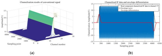
Figure 4.
Channelization results of conventional signal processing and envelope differentiation: (a) conventional signal-processing channelization results; (b) channelized intermediate-frequency data with envelope differential processing.
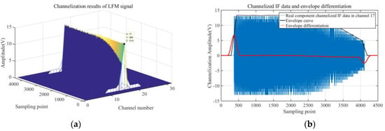
Figure 5.
Channelization results of LFM signal processing and envelope differentiation: (a) LFM signal channelization results; (b) channelized intermediate-frequency data with envelope differential processing.
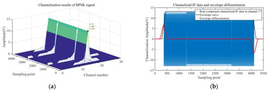
Figure 6.
Channelization results of BPSK signal processing and envelope differentiation: (a) BPSK signal channelization results; (b) channelized intermediate-frequency data with envelope differential processing.
Performance comparisons against conventional methods (Figure 7a, Figure 8a and Figure 9a) quantify significant improvements in low-SNR regimes. Specifically, the envelope differentiation technique reduces RMSE relative to traditional approaches at SNRs between −8 dB and −2dB. This discrepancy arises because traditional threshold-based TOA estimation algorithms inherently depend on signal pulse amplitude measurements for threshold calculation. Under low-SNR conditions, these amplitude measurements exhibit significant inaccuracies due to noise corruption, propagating errors into the threshold decision process. In contrast, the proposed envelope differentiation method circumvents this dependency by directly extracting temporal features from the received signal envelope. This non-threshold-based approach maintains robustness against noise perturbations, thereby enabling more precise TOA estimation in challenging low-SNR scenarios. At higher SNRs (>−2 dB), both methods achieve comparable accuracy, with an RMSE below 1 × 10⁻⁷, highlighting the proposed method’s particular advantage in challenging electromagnetic environments.
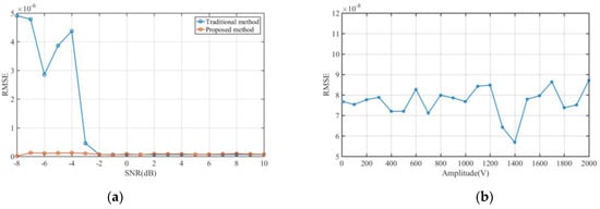
Figure 7.
RMSE estimation results for conventional signal TOA: (a) RMSE variation with SNR; (b) RMSE variation with pulse amplitude.
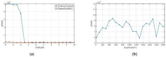
Figure 8.
RMSE estimation results for LFM signal TOA: (a) RMSE variation with SNR; (b) RMSE variation with pulse amplitude.
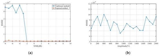
Figure 9.
RMSE estimation results for BPSK signal TOA: (a) RMSE variation with SNR; (b) RMSE variation with pulse amplitude.
Fixed-SNR (5 dB) experiments with varying pulse amplitudes (10–2000 dynamic range) confirm the algorithm’s robustness to signal intensity fluctuations. As shown in Figure 7b, Figure 8b and Figure 9b, TOA estimation of the RMSE remains stable within [5 × 10⁻⁸, 1 × 10⁻⁷] across all tested amplitudes, achieving amplitude invariant detection without threshold calibration. This innovation eliminates the critical dependency on amplitude-dependent thresholding in traditional TOA estimation, establishing a threshold-agnostic detection capability.
4. Discussion
Compared with the traditional method, in this paper, TOA is extracted under different signal types and different SNRs, and the experimental results are shown in Figure 4, Figure 5, Figure 6, Figure 7, Figure 8 and Figure 9. Compared with the traditional threshold method, the proposed method eliminates the need to use a trigger threshold and has the advantages of high accuracy and reliability. In addition, in order to verify the noise resistance of the method, Gaussian white noise with different SNRs is added during the processing, and the method proposed in this paper can still accurately determine the TOA. The results show that it is highly applicable in electronic countermeasures, there is no need to change the main structure, and it can be modified to the TOA detection method only in the intermediate processing stage, which is simple to calculate, and then can be used for the detection of different types of signals. Correlation convolution methods exhibit inferior accuracy and reliability under low-SNR conditions, while time-frequency methods and deep learning-based approaches impose prohibitive computational complexity and poor real-time performance, rendering them impractical for engineering applications. The proposed method, featuring simple calculations, effectively improves the estimation accuracy of pulse width, repetition frequency estimation, and other parameters, and in terms of engineering applications, has a greater value. However, this method demonstrates poor adaptability to high-frequency noise and complex signals due to the inherent sensitivity of differentiation processing to high-frequency noise, particularly under low-SNR conditions. Additionally, in multipath environments, signal envelope distortion occurs, complicating the ability of differentiation processing to accurately track the true signal front, both of which contribute to inaccurate TOA detection.
5. Conclusions
In this paper, a digital channelized receiver design method based on first-order envelope differentiation of the signal is proposed. The approach is validated through time-aligned extraction of signals from different regimes by estimating the peak occurrence location. Experimental results demonstrate that the proposed method significantly enhances both reliability and accuracy compared to conventional techniques. A key contribution lies in the ability to accurately extract the TOA through envelope differentiation while maintaining noise-robustness for signals with large transient dynamics. This innovation resolves the long-standing issue of amplitude-dependent TOA estimation errors in wideband receivers. The robustness is verified across varying SNRs and amplitude conditions. Additionally, the proposed framework can be readily integrated into existing signal arrival-time extraction methodologies, expanding its applicability to broader engineering scenarios. The novel combination of envelope differentiation and time-aligned processing introduces a new method for TOA estimation in digital receivers, with potential applications in cognitive radar systems and wireless localization networks.
Author Contributions
Conceptualization, B.C. and M.L.; methodology, B.C. and M.L.; software, B.C.; validation, B.C., M.L. and Q.L.; formal analysis, B.C.; investigation, B.C.; resources, M.L.; data curation, B.C.; writing—original draft preparation, B.C.; writing—review and editing, M.L. and Q.L.; visualization, B.C.; supervision, M.L.; project administration, M.L.; funding acquisition, M.L. All authors have read and agreed to the published version of the manuscript.
Funding
This research was supported by the Guangxi Key Technologies R&D Program (No. GuikeAB23026147), Guangxi Science and Technology Major Program (No. GuikeAA23023010), and Guangxi Baise Scientific Research and Technology Development Plan Project (No. Baike202432012).
Data Availability Statement
The code and data are available from the corresponding author.
Conflicts of Interest
The authors declare no conflicts of interest.
References
- Liu, M.; Liao, G.; Yang, Z.; Song, H.; Gong, F. Electromagnetic Signal Classification Based on Deep Sparse Capsule Networks. IEEE Access 2019, 7, 83974–83983. [Google Scholar] [CrossRef]
- Oliveira, A.; Backx, D. Detection in the Fractional Fourier Domain for Digital Wideband ESM Receivers in Electronic Warfare. In Proceedings of the 2024 21st European Radar Conference (EuRAD), Paris, France, 25–27 September 2025. [Google Scholar] [CrossRef]
- Benson, S.R.; Chen, C.-I.H. Adaptive Thresholding for High Dual-Tone Signal Instantaneous Dynamic Range in Digital Microwave Receiver. IEEE Trans. Instrum. Meas. 2011, 60, 1869–1875. [Google Scholar] [CrossRef]
- George, K.; Chen, C.; Tsui, J. Extension of Two-Signal Spurious-Free Dynamic Range of Wideband Digital Receivers Using Kaiser Window and Compensation Method. IEEE Trans. Microw. Theory Tech. 2007, 55, 788–794. [Google Scholar] [CrossRef]
- Lin, E.; Chen, C.; Liou, L.L.; Lin, D.M. Performance analysis of digital wideband receiver based on reconstruction of compressed sensing data. In Proceedings of the 2017 IEEE Radar Conference (RadarConf), Seattle, WA, USA, 8–12 May 2017. [Google Scholar] [CrossRef]
- Zhang, H.; Liu, M.; Chen, Y.; Zhao, N. Blockchain and timely auction mechanism-based spectrum management. Future Gener. Comput. Syst. 2025, 166, 107703. [Google Scholar] [CrossRef]
- Li, M.; He, G.; Wang, J. Wideband Digital Channelized Receiver Design Based on Double Sub-Nyquist Sampling. Electron. Inf. Warf. Technol. 2013, 28, 63–68. [Google Scholar]
- Zuo, Y.; Gao, X. The Comparison of Two Ways for Digital Channelization. Electron. Inf. Warf. Technol. 2016, 31, 5. [Google Scholar]
- Lu, Y.; Zheng, G.; Wang, L. A Technique to Design Wideband IF Digitized Receiver Based on Polyhase Filtering. J. UEST China 2003, 32, 133–136. [Google Scholar]
- Liu, M.; Yi, F.; Liu, P.; Li, B. Cramer-Rao Lower Bounds of TDOA and FDOA Estimation Based on Satellite Signals. In Proceedings of the 2018 14th IEEE International Conference on Signal Processing (ICSP), Beijing, China, 12–16 August 2018. [Google Scholar] [CrossRef]
- Guvenc, I.; Sahinoglu, Z. Threshold-based TOA estimation for impulse radio UWB systems. In Proceedings of the 2005 IEEE International Conference on Ultra-Wideband, Zurich, Switzerland, 5–8 September 2005. [Google Scholar] [CrossRef]
- Yu, L.; Laaraiedh, M.; Avrillon, S.; Uguen, B.; Keignart, J.; Stephan, J. Performance evaluation of threshold-based TOA estimation techniques using IR-UWB indoor measurements. In Proceedings of the European Wireless Conference, VDE, Poznan, Poland, 18–20 April 2012. [Google Scholar]
- Zehavi, E. Estimation of Time of Arrival for Rectangular Pulses. IEEE Trans. Aerosp. Electron. Syst. 1984, AES-20, 742–747. [Google Scholar] [CrossRef]
- Chan, Y.; Lee, B.; Inkol, R.; Chan, F. Estimation of Pulse Parameters by Convolution. In Proceedings of the 2006 Canadian Conference on Electrical and Computer Engineering, Ottawa, ON, Canada, 7–10 May 2007. [Google Scholar] [CrossRef]
- Xu, J.; Ren, L.; Jiang, Z.; Mao, E. TOA estimation for unknown signal under low SNR condition based on accumulation. In Proceedings of the International Radar Conference, IET, Hangzhou, China, 14–16 October 2016. [Google Scholar] [CrossRef]
- Sun, C.; Wang, S.; Zhu, J. Research of TOA Estimation Based on Auto–correlation Algorithm. Microprocessors 2014, 35, 39–43. [Google Scholar] [CrossRef]
- Tan, X.; Li, H.; Fan, C. Estimation Algorithm of Radar Signal Arrival Time Based on Correlated Accumulation. J. Proj. Rocket. Missiles Guid. 2018, 38, 161–164+169. [Google Scholar] [CrossRef]
- Qiu, Z.; Wang, P.; Zhu, J.; Tang, B. NYFR output pulse radar signal TOA analysis using extended Fourier transform and its TOA estimation. J. Syst. Eng. Electron. 2017, 28, 212–223. [Google Scholar]
- Qi, X.; Liu, H.; Ma, T. Arrival time estimation of LFM radar signals based on Morlet wavelets transform. Electron. Des. Eng. 2017, 25, 59–64. [Google Scholar] [CrossRef]
- Yi, Z. Research on LPI Radar Signal Detection and TOA Estimation Method Based on Deep Learning. Master’s Thesis, Harbin Engineering University, Harbin, China, 2022. [Google Scholar]
- Ji, H.; Wang, L.; Zhang, S.; Peng, C.; Zhou, W. Multi-Feature Fusion TOA Algorithm Based on Deep Learning and Compressed Sensing. In Proceedings of the 2024 7th International Conference on Information Communication and Signal Processing (ICICSP), Zhoushan, China, 21–23 September 2025. [Google Scholar] [CrossRef]
- Luo, Z.; Tao, T.; Liu, J. TOA Estimation Scheme Based on CNN for B-IFDM-Based Preambles. In Proceedings of the 2019 IEEE 89th Vehicular Technology Conference (VTC2019-Spring), Kuala Lumpur, Malaysia, 28 April–1 May 2019. [Google Scholar] [CrossRef]
- Sangpisit, W.; Wardkein, P.; Kiranon, W.; Loescharataramdee, C. A novel derivative envelope detector. IEEE Trans. Consum. Electron. 2002, 44, 1396–1405. [Google Scholar] [CrossRef]
- Reyes, L.; Silveira, F. Gain, Signal-to-Noise Ratio and Power Optimization of Envelope Detector for Ultra-Low-Power Wake-Up Receiver. IEEE Trans. Circuits Syst. II Express Briefs 2019, 66, 1703–1707. [Google Scholar] [CrossRef]
- Liu, M.; Liu, C.; Chen, Y.; Yan, Z.; Zhao, N. Radio Frequency Fingerprint Collaborative Intelligent Blind Identification for Green Radios. IEEE Trans. Green Commun. Netw. 2023, 7, 940–949. [Google Scholar] [CrossRef]
Disclaimer/Publisher’s Note: The statements, opinions and data contained in all publications are solely those of the individual author(s) and contributor(s) and not of MDPI and/or the editor(s). MDPI and/or the editor(s) disclaim responsibility for any injury to people or property resulting from any ideas, methods, instructions or products referred to in the content. |
© 2025 by the authors. Licensee MDPI, Basel, Switzerland. This article is an open access article distributed under the terms and conditions of the Creative Commons Attribution (CC BY) license (https://creativecommons.org/licenses/by/4.0/).